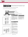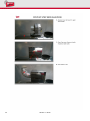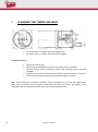
1
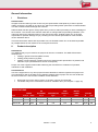
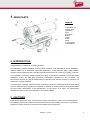
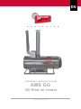
EN Installation and User manual AMS GG Oil fired air heater Holland heats the world Introduction Dear customer, Thank you for purchasing our oil fired air heater. This installation and user manual contains all information to get familiar with this product. In order to ensure that your new equipment will always work properly and efficiently and to ensure your personal safety, we recommend to read through this installation and user manual thoroughly and to take particular note of the warning and safety instructions before starting the machine for the first time. This oil fired air heater (AMS GG ideal for heating in greenhouses and plastic tunnels. The heaters are also excellent for heating poultry sheds or pig sties. Particularly in their first stages of life, young animals need a lot of heat, whether they are poultry or pigs. Optimum temperatures right from the start have a decisive impact on their development, health and general performance. The heaters can also be used for heating or frost protection in areas used for the storage and/or preservation of potatoes and tuberous crops. However these products should not be destined for human consumption. The AMS GG creates the right conditions for your room. This heater is available for use with kerosene/paraffin oil or diesel.. The heater is installed exactly where it will be most effective in generating heat. AMS GG devices have connections for floating contacts. This allows them to be controlled via thermostats or 24 Volts signal current. There is also the possibility for manual heating and ventilation. The heaters are secured with a burner controller which has a photocell flame security and maximal thermostat. If for some reason the appliance does not ignite or the flame is extinguished, the oil supply is immediately cut off. One solenoid valve unit ensures high levels of safety. No oil can escape unburnt. This manual is intended for the technical installer and end user of the AMS GG. The information you need can be found through the table of contents in the manual. This is the original installation and user manual. To obtain more information or to order other manuals, contact Holland Heater. Take good care of this manual and store it near the heater! Copyright 2012 by Holland Heater Holland Heater De Lier B.V. Leehove 2 2678MC DE-LIER The Netherlands Tel: Fax: E-mail: Website: 2 +31 (0)174 51 67 41 +31 (0)174 51 80 21 [email protected] www.hollandheater.nl Version 1 / 2012 General information I Disclaimer Holland Heater All rights reserved. Nothing in this version may be copied and/or made public by means of printed matter, photocopy, microfilm or any other way, without preceding written permission of Holland Heater. This also includes related drawings and schemes. Holland Heater has the right to change parts at any moment, without preceding or direct knowledge of the customer. The content of this manual could also be changed without preceding notification. This manual is valid for the standard version of the oil fired air heater. Holland Heater can not be held responsible for possible damage or injury resulting from the deviant specifications of the standard version delivered device. This manual has been written with all possible care, but Holland Heater can not be held responsible for possible failures in this manual or the consequences thereof. II Product description Intended use The AMS GG may only be used for the purpose for which it is intended. The AMS GG has been developed for: heating in greenhouses and plastic tunnels; heating poultry sheds or pig sties; heating or frost protection in areas used for the storage and/or preservation of potatoes and tuberous crops. (Not destined for human consumption) Proper use of the equipment also entails observing the manufacturer's conditions of operation, maintenance and installation. Unintended use Use of the equipment for any other purpose as described above shall be regarded as improper use. The manufacturer will not be liable for any damage resulting from improper use; the user shall bear the sole risk thereof. A few remarks in addition to this statement: Diesel fuel may not be used in poultry or pig sties, petrol is recommended. The Heater may not be connected to a hose or ventilation duct. (see chapter 3.1 page 15) SPECIFICATIONS Type POWER Kcal./h kW/h AMS GG 50 AMS GG 70 AMS GG 80 41,280 61,318 69,316 48.0 71.3 80.6 AIR MOVEMENT M³ /h CONSUMPTION kg/h TANK CAPACITY Ltr. MOTOR POWER Watt 1,900 3,500 3,900 4.0 6.0 6.8 70 120 120 300 750 750 Version 1 / 2012 ELECTRIC Hz Volt 50/60 50/60 50/60 230 230 230 3 III Used symbols Warning of a general danger Warning of dangerous voltage IV Identification of the air heater An identification plate can be found on the delivered air heater. It contains information about the producer, model, serial number etc. The image on the right is an example of what the identification plate could look like. V Ordering spare parts When ordering spare parts, always indicate the following: Code no. and description of part or item number with description and manual number for encoded parts; Number of original invoice; Electricity supply, e.g. 230V, 50/60 Hz. 4 Version 1 / 2012 1 Precautions and warnings General Before using the heater, read the safety instructions and make sure that the heater, fuel lines, oil tank, electrical supply and room thermostat are connected as described. Any unlawful alterations to the heater will rule out manufacturer liability for any resultant damage. Always follow local- and national regulations. Installation and maintenance should only be carried out by persons who have the training, knowledge or practical experience to ensure that the installation and maintenance is done properly. When fueled with diesel this heater is not suited for CO2 enrichment in greenhouses or plastic tunnels where plants or crops are being grown. The AMS GG is a heater for use in mentioned rooms. Use of the equipment for any other purpose shall be regarded as improper use. The manufacturer will not be liable for any damage resulting from improper use; the user shall bear the sole risk thereof. No account is taken with general hazard of fire in this manual. Consult the fire insurance company and/ or the local fire brigade for more information. With storing manure, gasses are formed which are partly dissolved. These poisonous and explosive gases (e.g. sulphurhydrogen and methane) can be released during stirring and rinsing. With a source of ignition a big explosion may occur. To prevent a hazardous situation shut off the heaters completely before stirring or rinsing. Also observe the following points: • Close the doors when manure is stored outside; • Ventilate the room thoroughly. Note the distance of the heater to feeding and drinking equipment and to plants in glasshouses concerning dehydration. Always use oil-resistant lines with the correct line clips! The "ventilate" mode is particularly useful in the summer. However, make sure that there is enough oil in the tank, since the oil pump could seize if it is not being lubricated by the oil. It is advised to use a room thermostat with a differential of ± 2C. It will activate the heater when the room temperature drops 1C below the set temperature, and deactivate when the room temperature rises 1C above the set temperature. Using a thermostat of this kind will reduce the likelihood of failures and improve the performance of the heater. Version 1 / 2012 5 Appendices Appendix I EC Declaration of Conformity We declare that the design and model of the machine described above being placed on the market by ourselves complies with the relevant health and safety requirements of the EC Directive. The heater described in this manual meets the requirements of the following EEC directives: • Machine Directive 89/392/EEC • Low-voltage Directive 73/23/EEC Appendix II Accessories A range of accessories for use when setting up a heater installation or modifying an existing installation is available. The products include: Oil line For connecting heaters to oil boxes or directly to an oil tank. Available in various diameters. Oil-resistant. Oil box For use when connecting several heaters to a common oil tank. Complete with fittings, nonreturn valve and bleed valve. Line clips For attaching oil lines to oil pump and oil boxes. Available in various sizes. Room thermostat Ready-mounted on a panel with 7 meters of connecting cable. 6 Version 1 / 2012 1. MAIN PARTS Legend: 1.Ventilation unit 2.Comb. head 3.Chambre 4.Fan 5.Conveyor 6.Panel 7.Tank 8.Filter 9.Plug 10. . Fan protec. 11.Nameplate 2. INTRODUCTION Congratulations on making an excellent purchase. This handbook contains standards covering safety, operation and maintenance for the INDIRECT DIRECT mobile hot air generators. Keep this handbook for ready reference and in good condition: together with the spare parts list, it provides important information in the event of necessity or upkeep. It is advisable to read this manual carefully and apply all operations described scrupulously before installation, during use and when performing maintenance operations on the generator. The Manufacturer declines any and all responsibility for damage to the machine, persons or things by non observance of these standards. The instructions, drawings, tables and other information herein are confidential technical data and as such no material may be reproduced, completely or partially, or communicated to third parties without the prior written authorisation of the Manufacturer, as sole owner of all rights. The Manufacturer reserves the right to make any modifications it considers suitable. 3. CAUTIONS Read the following instructions carefully before starting the machine to gain a clear understanding of the operating procedures essential for optimal performance while avoiding errors which may become dangerous. Always observe the instructions provided by the manufacturer. Version 1 / 2012 7 This mobile generator can only be used on fire-proof floors. SAFETY DISTANCE: 2 metres from walls or objects. - The generator must not be used in rooms containing explosives, gas fumes, combustible liquids and flammable materials. - The burner must be cleaned frequently if used in dusty environments. 3.1 Use in environments where people are not normally present: mod. DIRECT 3.2 Use in environments where people are normally resent: mod. DIRECT 4. -notices should be affixed to entrances forbidding people to remain in such areas; -the generators must only be used to dry rooms, provided sufficient air for combustion is avail able; -the amount of air required is calculated when the room has a volume in cubic metres at least 10 times the rated calorific output (in kW) of all equipment used in the room; -normal air circulation through windows and doors must be ensured. -direct generators may be used in well-aired rooms and when the percentage of polluting substances in the air does not reach levels harmful to health -good airing is provided, for example, when the volume of the room in cubic metres is at least 30 times the rated calorific output (in kW) of all equipment used in the room and when air circulation is ensured by windows and doors or permanent apertures having a total crosssection in square metres of at least 0,003 times the rated calorific output (in kW) of all equipment used in the room; -the concentration of polluting substances in the air can be considered acceptable provided it does not reach maximum values and that the percentage of oxygen in the air is greater than 17% by volume; -these plant systems must not be used for continuous heating of stables and animal rearing centres. DESCRIPTION OF MACHINE AND APPLICATIONS The DIRECT mobile hot air generator is available with various outputs and was designed and manufactured to meet special needs, such as temporary heating in outside or semiopen areas and drying applications where operators are not required. It is easy to move the unit since it is mounted on a sturdy chassis with large diameter wheels. Functional features were designed to simplify use as far as possible.The INDIRECT mobile hot air generator is also available with various outputs and was designed to meet further needs not available with the DIRECT model: as well as drying applications, this unit is ideal for heating any interior civil, agricultural and industrial environment. The wide range of models provides logical and optimal solutions to all heating requirements. 8 Version 1 / 2012 5. RECOMMENDATIONS PRIOR TO USE The INDIRECT generators can be used in interior environments but nevertheless require a sufficient supply of fresh air for correct combustion. In the event that the air supply is inadequate, connect the unit’s air intake to the outside. The DIRECT generators are used exclusively in exterior or well aired environments. Avoid use in the presence of foodstuffs. IMPORTANT! Never obstruct the unit’s intake grille. All work on the equipment must be performed cold with the mains power detached. The electrical connection must be fitted with an efficient earth (ground). Do not place flammable or explosive materials near the unit. There must be sufficient exchange of air where the unit is installed and no powder residues, gas or flammable/toxic vapours at high temperatures. Do not fill the fuel tank while the unit is working; any drips of fuel on the floor must be dried carefully. Make sure that the fan does not attract papers, cloths, powders or any other material which may obstruct or damage the unit. Do not start the generator without fuel oil; despite the intervention of the flame control device, the fuel oil pump could grip. Only use the fuel oil indicated on the information plate giving technical data for the machine. N.B. Never add petrol or other solvents to approved fuels; when operating at particularly low temperatures, use fuels with readily available additives. 5.1 Electrical Connection Before starting the unit, make sure that the mains electricity supply corresponds to the supply value indicate on the label affixed to the machine. - Mains connection must conform to applicable standards, with a properly functioning earth (ground) connection. Call in a skilled electrician to fit a high sensitivity differential switch with a 30 mA or lower tripping threshold. - In case of need, it is possible to use feeding cable extension with wire section of 1,5 mm 2 for lenghts up to 10 mt. and 2,5 mm 2 for lenght between 10 and 30 mt. If the original power supply cable must be replaced, use a new cable having a suitable crosssection with an earth (ground) lead; the cable must have a continuous insulating sheath suitable for use both outside and inside; combustion product discharge must take place in conformity with applicable standards. Version 1 / 2012 9 5.2 Connection To The Stack INDIRECT models require a Exhause discharge system. A stack must be installed (flexible tubing is allowed) with a minimum diameter of 120 - 150 mm. DIRECT models should be used exclusively in well aired environments. Please, connect the chimney using the union kit ( see picture ) Chimney Union kit STACK Flue gas exhaust chimney hood 10 Version 1 / 2012 Version 1 / 2012 11 12 Version 1 / 2012 6. START – STOP 6.1 Start (without environment thermostat) Fill the tank with fuel. Insert the plug in the mains socket (the red LED comes ON). Place the ignition switch to ON (the green LED comes ON and the fan begins operating). The automatic ignition cycle commences, through the control equipment. After a few seconds of automatic monitoring, the generator begins operating normally. If the unit comes to a halt because of minor functional irregularities and the RESET PUSH-BUTTON LED comes ON, press this button to repeat the ignition cycle. 6.2 Stop (without environment thermostat) 6.3 Place the main switch to OFF. Combustion halts while the fan continues to cool the interior of the generator. During this stage, fan operation may be continuous or intermittent until complete cooling is achieved, as measured by the post-cooling thermostat located on-board the boiler. Start (with environment thermostat) The unit is pre-set for connection to an environment thermostat (not supplied as standard). Connection should be made using the plug on the control panel. Having set the environment thermostat, place the switch to AUT. To halt the generator, operate either the main switch or the environment thermostat. In both cases, the generator undergoes a correct cooling cycle. When the machine is in normal duty condition the reset button will flash. In case of bad working, the reset button will stay alight for about 10 sec. Please detect and solve the problem causing the failure and reset the machine by pressing the button.(only for SATRONIC DKO 970) Version 1 / 2012 13 7. CLEANING THE TURBO AIR INLET The turbo disc is an integral part of the tapered inlet. To clean the disc, it must be removed from the support. Proceed as follows: Remove the fuel oil pipe. Slide out the photosensitive cell and the HT leads from the electrodes. Unscrew the four screws securing the head to the boiler (the head is removed complete). Slacken the two screws: the entire internal section of the head slides out; only the cylindrical body and the tapered inlet remain accessible for cleaning. N.B. - When refitting the combustion head after cleaning operations, do not move the nozzle holder. Make sure, as required, that the nozzle is flush with the inside of the turbo. The position of the electrodes must be respected, as well as the angle of the air adjustment fins. 14 Version 1 / 2012 8. MAINTENANCE The maintenance intervals recommended in this manual refer to generator operation of 8 ÷ 10 hours/day. Every month: clean the photosensitive cell, the ignition electrodes and the flame turbo. Every 2 months: clean the fuel filter. Direct 27kW - 30kW - 40kW - 50kW Indirect 20kW - 25kW : every three months or every 300 hours of operation, replace the filter of the diesel. Every 6 months: clean the fuel tank. FUEL OIL FILTER Unscrew the clear cup and remove deposits. Slide out the filter element and clean. Fill the fuel cup to approx. 1/4 to facilitate operational reset. Refit all components making sure that gaskets are properly Fitted and located. PHOTOSENSITIVE CELL • Slide out the photosensitive cell. • Clean the lens with a soft cloth. • Refit the cell in its seat with reference to the centring tooth. Version 1 / 2012 15 10. TROUBLE-SHOOTING TABLES Never halt the generator simply by removing the power plug. This would exclude post-cooling. Never change the fuel oil pump pressure setting. This would modify all combustion features. When replacing the nozzle, use a spare with an identical capacity to the nozzle fitted by the manufacturer 16 Version 1 / 2012 Version 1 / 2012 17 18 Version 1 / 2012 Version 1 / 2012 19 Copyright 2012 by Holland Heater Holland Heater De Lier B.V. Leehove 2 2678MC DE-LIER The Netherlands Tel: Fax: E-mail: Website: +31 (0)174 51 67 41 +31 (0)174 51 80 21 [email protected] www.hollandheater.nl