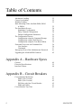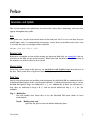
1
AlterPath PM
User Guide
Version 1.5.0
Revision 2
This document contains proprietary information of Cyclades and is not to be disclosed or used
except in accordance with applicable contracts or agreements.
©
Cyclades Corporation, 2004
AlterPath PM Version 1.5.0 User Guide
October 2004
Copyright © Cyclades Corporation, 2004
We believe the information in this manual is accurate and reliable. However, we assume no responsibility, financial or otherwise, for any consequences of the use of this product or manual. This
manual is published by Cyclades Corporation, which reserves the right to make improvements or
changes in the products described in this manual as well as to revise this publication at any time and
without notice to any person of such revision or change. The firmware covered in this manual is
v1.5.0. All brand and product names mentioned in this publication are trademarks or registered
trademarks of their respective holders.
Cyclades, Cyclom and AlterPath are either trademarks of registered trademarks of Cyclades Corporation in the United States and in other countries. All other trademarks are the property of their
respective holders.
All rights reserved. This document may not, in whole or part, be copied, photocopied, reproduced,
translated, or converted to any electronic or machine-readable form without the prior written
consent of Cyclades Corporation, 41829 Albrae Street, Fremont, CA 94538, USA. Telephone (510)
771-6100. Fax (510) 771-6200. www.cyclades.com.
Product Version 1.5.0
Table of Contents
Preface
Purpose
Audience and User Levels
How to use this Guide
Additional Documentation and Help
Conventions and Symbols
Fonts
Hypertext Links
Glossary Entries
Quick Steps
Note Box Icons
1
1
2
2
3
3
3
3
3
4
Chapter 1 - Introduction and Overview
Introducing Cyclades
The AlterPath PM 5
Standalone Configuration
Daisy-chained Configuration
Integrated Configuration
What’s in the box
Input Power Cable Options for the
AlterPath PM8i and PM10i
Optional Outlet Cable Package
Safety Instructions
5
7
7
8
9
13
14
15
Chapter 2 - Installation, Configuration, and Usage
Introduction
System Requirements
Pre-Install Checklist
Rack Installation
Connecting the Hardware
Connecting the Power Cable
Connecting to the Serial Port
Accessing the System Console
Rack-Mounting
Temperature
Elevated Operating Ambient Temperature
Reduced Air Flow
User Guide
17
17
18
18
18
19
20
21
21
21
21
21
3
Table of Contents
Mechanical Loading
Circuit Overloading
Reliable Earthing
Rack Mounting of the AlterPath PM8i, PM10
or PM10i
The Installation Process
Standalone Configuration
Daisy-Chained Configuration
Default Configuration Parameters
The Configuration Process
Configuration using the Command Prompt
Configuration using a Web Browser
Configuration using the Text-Based Menu
Functional Overview and Command Set
User Interface
Commands
Emergency Reset of the Administrator Password
Upgrading the AlterPath PM Firmware
22
22
22
22
24
24
24
25
25
25
26
26
26
26
27
41
42
Appendix A - Hardware Specs
General
Electrical Specifications
Interface Pinouts
49
52
60
Appendix B - Circuit Breakers
Circuit Breaker Mechnism
PM20 (30A Version)
PM10 (30A Version)
PM Units with One Circuit Breaker
PM8i and PM10i
Circuit Breaker Trip Time
4
61
61
62
62
63
63
AlterPath PM
Preface
Preface
Purpose
The purpose of this guide is to provide instruction for users to independently install,
configure, and maintain the AlterPath PM.
The AlterPath PM can be used in one of three configurations:
•
Standalone - independent of any other hardware device.
•
With a Cyclades-TS or AlterPath ACS.
•
With any other console/terminal management device.
When used with the ACS/TS family, the AlterPath PM will yield a superior feature set. With
this usage, the configuration will be different and the ACS/TS manual should be referenced
for the setup.
Audience and User Levels
This guide is intended for the user who is responsible for the deployment and day-to-day
operation and maintenance of the AlterPath PM. It assumes that the reader understands
networking basics and is familiar with the terms and concepts used in Local and Wide Area
Networking. Each configuration task will be separated into a section (a clickable link on the
PDF file) for each user type.
User Guide
1
How to use this Guide
How to use this Guide
This guide is organized into the following sections:
•
Chapter 1 - Introduction and Overview contains an explanation of the product and its
default setup. It also includes safety guidelines to be followed.
•
Chapter 2 - Installation, Configuration, and Usage explains how the AlterPath PM should
be connected. It describes the basic configuration process to get the AlterPath PM up and
running for its most common uses.
•
Appendix A - Hardware Specs gives a product overview, circuit breaker trip times, and
electrical specifications for the AlterPath PM.
Additional Documentation and Help
There are other Cyclades documents that contain background information about Console
Port Management and the Cyclades product line. These are:
•
AlterPath Console Server User Manual
•
AlterPath Console Server Reference Guide
•
Cyclades-TS User Guide
•
Cyclades’ Console Management in the Data Center
•
Cyclades’ Product Catalog
The ACS User Manual, ACS Reference Guide and TS User Guide are available from the
following site:
http://www.cyclades.com/support/downloads.php
2
AlterPath PM
Preface
Conventions and Symbols
This section explains the significance of each of the various fonts, formatting, and icons that
appear throughout this guide.
Fonts
This guide uses a regular text font for most of the body text and Courier for data that you
would input, such as a command line instruction, or data that you would receive back, such
as an error message. An example of this would be:
telnet 200.200.200.1 7001
Hypertext Links
References to another section of this manual are hypertext links that are underlined (and are
also blue in the PDF version of the manual). When you click on them in the PDF version of
the manual, you will be taken to that section.
Glossary Entries
Terms that can be found in the glossary are underlined and slightly larger than the rest of
the text. These terms have a hypertext link to the glossary.
Quick Steps
Step-by-step instructions for installing and configuring the AlterPath PM are numbered with a
summarized description of the step for quick reference. Underneath the quick step is a more
detailed description. Steps are numbered 1, 2, 3, etc. Additionally, if there are sub-steps to a
step, they are indicated as Step A, B, C, and are nested within the Step 1, 2, 3, etc. For
example:
Step 1: Modify files.
You will modify four Linux files to let the AlterPath PM know about its local
environment.
Step A: Modify pslave.conf.
Open the file plsave.conf and add the following lines . . .
User Guide
3
Conventions and Symbols
Note Box Icons
Note boxes contain instructional or cautionary information that the reader especially needs
to bear in mind. There are five levels of note box icons:
Tip. An informational tip or tool that
explains and/or expedites the use of
the AlterPath PM.
Important! An important tip that
should be read. Review all of these
notes for critical information.
Warning! A very important type of
tip or warning. Do not ignore this
information.
DANGER! Indicates a direct danger
which, if not avoided, may result in
personal injury or damage to the
system.
4
AlterPath PM
Chapter 1 - Introduction and Overview
Chapter 1 - Introduction and Overview
Introducing Cyclades
Cyclades is a data center fault management company that enables remote management of
servers, network equipment, and automation devices. Its products help data center managers
at enterprise, telecommunication, and Internet companies to maximize network and server
availability. This results in decreased maintenance costs, increased efficiency and
productivity, along with greater control, freedom, and peace of mind. Cyclades' advantage is
providing scalable products leveraging Linux technology for flexibility and ease of
customization.
The AlterPath PM
The AlterPath PM is an Intelligent Power Distribution Unit (IPDU) that enables remote power
control of servers and network gear. When used in conjunction with Cyclades console
servers, the AlterPath PM delivers easier management capabilities and faster problem solving
by integrating console access and power control into one single interface.
IT professionals can power off, power on, and reboot network devices using the same
console management session from any location via telnet, Secure Shell (SSHv2) or through a
secure Web session, which significantly streamlines the process. This can all be done without
the need for physical access to the hardware.
The AlterPath PM delivers accurate, real-time global current monitoring of all connected
devices via the user interface screen or locally through an LED digital display. Users have the
ability to set a current alarm threshold that, once exceeded, will cause the AlterPath PM to
sound an alarm or send a notification message, or both. The LED current display also blinks
when the alarm threshold is exceeded.
The AlterPath PM also incorporates a sequential power-up feature that prevents all power
outlet receptacles from turning on at once, eliminating the potential of current surges that
could render the equipment inoperable. Together with the global current monitoring, the
sequential power-up feature lets users safely install more equipment on existing power
circuits without the worry of current overloads.
The IPDU has a fixed number of power-outlet receptacles, but with daisy-chaining
capabilities, users can increase capacity by connecting the control interfaces of several
AlterPath PMs in a series.
User Guide
5
The AlterPath PM
The AlterPath PM allows one administrator and up to eight users (not simultaneously) to
connect to it through its RS-232 serial port. After a successful authentication it performs the
following functions:
•
Reads and displays the total current being used by the entire AlterPath PM.
•
Manages power outlets (by powering them on and off, locking and unlocking them, and/
or power cycling them).
•
Manages users.
•
Monitors power variables.
•
Can be used as a stand-alone IPDU (independent of any other hardware) and controlled
by any simple terminal access program like Minicom on Linux or HyperTerminal on
Microsoft operating systems.
•
Ethernet connection is available through the Cyclades-TS or AlterPath ACS to which the
AlterPath PM is connected. When used with the ACS/TS family, the AlterPath PM
allows you, via a configurable hotkey, to reboot servers without leaving your telnet/ssh
session. To do so, all you need to do is to press the hotkey and select a power management option from the displayed menu.
•
When used with the ACS/TS family, the AlterPath PM inherits the security of the console
server to which it is connected.
6
AlterPath PM
Chapter 1 - Introduction and Overview
Standalone Configuration
In this configuration, the console port of the AlterPath PM is connected to a computer
running HyperTerminal or Minicom. In this example, the AlterPath PM operates
independently of any other hardware such as the TS/ACS.
Figure 1: Standalone Configuration
Daisy-chained Configuration
This example shows three AlterPath PMs operating in a daisy-chained environment. They are
configured to be used independently from any other hardware such as the AlterPath ACS or
Cyclades-TS. The connections between the first PM and the computer with HyperTerminal/
Minicom will be the same as in Figure #1.
Figure 2: Daisy-chained Configuration
User Guide
7
The AlterPath PM
Integrated Configuration
In this configuration, the AlterPath PM is configured to work in conjunction with the
AlterPath ACS/Cyclades-TS. A user connects to the AlterPath PM by accessing the appropriate
console port of the TS/ACS. The setup/configuration for the ACS/TS can be found in the
AlterPath Console Server User Manual and the Cyclades-TS User Guide respectively. No
software configuration is needed on the AlterPath PM itself in this setup.
Figure 3: The AlterPath PM with an ACS or TS
If you want to daisy-chain with the AlterPath ACS or Cyclades-TS, the chain setup is similar to
the Daisy-chained Configuration, with the difference that the first AlterPath PM is connected
to the TS/ACS (instead of the workstation).
8
AlterPath PM
Chapter 1 - Introduction and Overview
What’s in the box
The AlterPath PM comes with one adapter and one RJ-45 cable. The RJ-45 cable connects to
Cyclades Console Servers, to another AlterPath PM in a daisy-chain solution, or to a PC (in this
case, along with an adapter). The RJ-45 - DB-9F adapter is used along with the RJ-45 cable to
connect to a PC’s COM port.
User Guide CD
RJ-45 straight-through cable
RJ-45 to DB-9F
straight-through adapter
RJ-45 loopback connector
Figure 4: The AlterPath PM8, its cables, connectors and other box contents
User Guide
9
What’s in the box
User Guide CD
RJ-45 straight-through cable
RJ-45 to DB-9 F
straight-through adapter
RJ-45 loopback connector
Figure 5: The AlterPath PM10, its cables, connectors, and other box contents.
10
AlterPath PM
Chapter 1 - Introduction and Overview
User Guide CD
RJ-45 straight-through cable
RJ-45 to DB-9 F
straight-through adapter
RJ-45 loopback connector
Figure 6: The AlterPath PM10i, its cables, connectors, and other box contents.
User Guide
11
What’s in the box
User Guide CD
RJ-45 straight-through cable
RJ-45 to DB-9 F
straight-through adapter
RJ-45 loopback connector
Figure 7: The AlterPath PM20, its cables, connectors and other box contents
12
AlterPath PM
Chapter 1 - Introduction and Overview
User Guide CD
RJ-45 straight-through cable
RJ-45 to DB-9 F
straight-through adapter
RJ-45 loopback connector
Figure 8: The AlterPath PM8i, its cables, connectors and other box contents
Depending on your site’s location, the input power cables included in the box will vary.
Following are the various cables listed with their corresponding countries.
Input Power Cable Options for the AlterPath PM8i and PM10i
•
CAB0089: 8.2ft 3-pin power cable for the US.
•
CAB0055: 8.2ft. 3-pin power cable for Australia & New Zealand.
•
CAB0087: 8.2ft. 3-pin power cable for Continental Europe.
•
CAB0088: 8.2ft. 3-pin power cable for the UK & Ireland.
NOTE:
User Guide
There are more options available. Please consult the Cyclades website
(www.cyclades.com) for more details.
13
What’s in the box
CAB0089 US Power Cord
CAB0087 Continental Europe
Power Cord
CAB0055 Australia/New
Zealand Power Cord
Input Power Cable and Harness
CAB0088 UK & Ireland Power Cord
Output Power Cable and Harness
Figure 9: Input Power Cables for the AlterPath PM8i
Optional Outlet Cable Package
8-outlet cables (C13 male to C14 female) with retaining clips (ACS0040). See above figure.
14
AlterPath PM
Chapter 1 - Introduction and Overview
Safety Instructions
Read all the following safety guidelines to protect yourself and your AlterPath PM.
DANGER! All outlets of the AlterPath PM output high voltage. Necessary
precautions should be taken.
DANGER! To help prevent electric shock, plug the AlterPath PM into a
properly grounded power source. The power cord is equipped with a threeprong plug to help ensure proper grounding. Do not use adapter plugs or
remove the grounding prong from the cable. Do not use extension cords with
AlterPath PM.
Important! AlterPath PM is intended for enterprise and indoor use only.
Important! To help protect the AlterPath PM from electrical power
fluctuations, use a surge suppressor, line conditioner, or uninterruptible
power supply.
Important! Be sure that nothing rests on the cables of the AlterPath PM and
that they are not located where they can be stepped on or tripped over.
Important! Do not spill food or liquids on the AlterPath PM. If it gets wet,
disconnect the power immediately and contact Cyclades.
User Guide
15
Chapter 1 - Introduction and Overview
DANGER! Do not push any objects through the openings of the AlterPath PM.
Doing so can cause fire or electric shock by shorting out interior components.
Important! Keep your AlterPath PM away from heat sources.
DANGER! There is a possibility of live feed for either Line or Neutral even if
one of the circuit breakers is disabled.
FCC Warning Statement
The AlterPath PM has been tested and found to comply with the limits for Class A digital
devices, pursuant to Part 15 of the FCC rules. These limits are designed to provide reasonable
protection against harmful interference when the equipment is operated in a commercial
environment. This equipment generates, uses, and can radiate radio frequency energy and, if
not installed and used in accordance with the Installation & Service Manual, may cause
harmful interference to radio communications. Operation of this equipment in a residential
area is likely to cause harmful interference in which case the user is required to correct the
problem at his or her own expense.
Canadian DOC Notice
The AlterPath PM does not exceed the Class A limits for radio noise emissions from digital
apparatus set out in the Radio Interference Regulations of the Canadian Department of
Communications.
L’AlterPath PM n’émete pas de bruits radioélectriques dépassant les limites applicables aux
appareils numériques de la classe A prescrites dans le règlement sur le brouillage
radioélectrique edicté par le Ministère des Communications du Canada.
User Guide
16
Chapter 2 - Installation, configuration and usage
Chapter 2 - Installation, Configuration, and Usage
Introduction
This chapter will allow you to install and configure the AlterPath PM. This information refers
to the standalone and daisy-chained modes only. For information about integrated use with
the ACS/TS, please consult the AlterPath ACS User Guide or the Cyclades-TS User Guide
respectively.
This chapter is divided into the following sections:
•
Functional Overview and Command Set
•
System Requirements
•
Pre-Install Checklist
•
The Installation Process
•
Default Configuration Parameters
•
The Configuration Process
System Requirements
Cyclades recommends either of the following specifications for configuring the
AlterPath PM:
•
Standalone, independent of any other hardware, accessed via a terminal access program
such as Minicom or HyperTerminal.
•
In conjunction with a console server such as the AlterPath ACS or Cyclades-TS.
User Guide
17
Pre-Install Checklist
Pre-Install Checklist
The AlterPath PM can be daisy-chained either while attached to a dumb terminal or PC
emulating a terminal, or while attached to an ACS/TS. If it is attached to an ACS/TS, there is
no need for a DB-9F straight-through adapter.
There are several things you will need to confirm prior to installing and configuring the
AlterPath PM:
1.
One or more RJ-45 - RJ-45 straight-through cables.
2.
A RJ-45 - DB-9F straight-through adapter (if the AlterPath PM is used in standalone or
daisy-chained mode only).
3.
A PC running a terminal emulation program (if the AlterPath PM is used in standalone or
daisy-chained mode only).
Rack Installation
Connecting the Hardware
This section explains how to connect the PM to equipment for initial testing. It is a two-step
process:
1.
Connect the AlterPath PM to an AC power source.
2.
Connect a device to one of the AlterPath PM's outlets.
Important! The suggested minimum screw size for wall-mounting the
AlterPath PM units is #10 (4.8 mm or 0.19 in or 3/16 in) or larger.
The RJ-45 cable included in the AlterPath PM package is minimum flame rated
VW-1 or FT-1 and has a maximum length of 10.00656 feet (3.05 meters).
18
AlterPath PM
Chapter 2 - Installation, configuration and usage
Important! Install your AlterPath PM near the power managed equipment and
in an easily accessible location.
Connecting the Power Cable
Connect the AlterPath PM’s power cable to a wall outlet.
Important! The following figure shows the AlterPath PM 0U model mounted on
a wall. When mounting to a stud, securely mount using a #10 or larger screw or
use a drywall fastener rated min. 25 lbs. (11.34 kg).
Figure 10: Connecting the AlterPath PM to a power source
Important! Install the AlterPath PM 0U model in a location where there is an
adjacent and accessible wall socket outlet.
User Guide
19
Rack Installation
Important! The wall socket outlet shall be installed near the equipment and
shall be easily accessible.
Important! The AlterPath PM 0U model unit must be plugged into a receptacle
protected by an appropriate Listed circuit breaker.
Connecting to the Serial Port
Plug one end of the RJ-45 cable into the AlterPath PM “In” (also labeled as “Console” in older
PM units) port. The other end of the RJ-45 cable should be connected to either a Cyclades
console server or to the RJ-45 to DB-9F adapter shipped with the product. In the latter case,
the adapter can then be connected to a DB-9 serial port in the workstation that will control
the AlterPath PM.
Console Port
or “In” Port
“Out” Port
Figure 11: Connecting an RJ-45 cable to the AlterPath PM
20
AlterPath PM
Chapter 2 - Installation, configuration and usage
Accessing the System Console
There are several ways to access the AlterPath PM. These methods are dependent on whether
you are using the AlterPath PM as a standalone device, or in conjunction with the Cyclades-TS
or AlterPath Console Server.
In standalone mode, local users can connect directly to the system console port (the “In”
port) of the AlterPath PM using the console cable with the corresponding adapter.
In TS/ACS integration mode, remote users can access the AlterPath PM's control port through
one of the following interfaces:
1.
Menu-driven interface: after using telnet or SSH to access the console port equivalent to
the managed device on the console server, you should type the power management hotkey (CTRL+P by default) and this will bring up a power management menu on the same
screen.
2.
Web interface: once you are logged into the Web interface of the console server, you can
access the power management functionality from the “Power Management” tab on the
Web interface.
For more details, please refer to the section called The Installation Process.
Rack-Mounting
The following considerations should be taken into account when rack-mounting the
AlterPath PM:
Temperature
The manufacturer's maximum recommended ambient temperature for the AlterPath PM is
122 ºF (50 ºC).
Elevated Operating Ambient Temperature
If the AlterPath PM is installed in a closed or multi-unit rack assembly, the operating ambient
temperature of the rack environment may be greater than room ambient temperature.
Therefore, consideration should be given to installing the equipment in an environment
compatible with the manufacturer’s maximum rated ambient temperature. See above.
Reduced Air Flow
Installation of the equipment in a rack should be such that the amount of air flow required for
safe operation of the equipment is not compromised.
User Guide
21
Rack Installation
Mechanical Loading
Mounting of the equipment in the rack should be such that a hazardous condition is not
achieved due to uneven mechanical loading.
Circuit Overloading
Consideration should be given to the connection of the equipment to the supply circuit and
the effect that overloading of circuits might have on overcurrent protection and supply
wiring. Appropriate consideration of equipment nameplate ratings should be used when
addressing this concern.
Reliable Earthing
Reliable earthing of rack-mounted equipment should be maintained. Particular attention
should be given to supply connections other than direct connections to the branch circuit,
such as power strips or extension cords.
Rack Mounting of the AlterPath PM8i, PM10 or PM10i
Step 1: Mount or place the AlterPath PM8i in a secure location.
Step 2: Connect the power cord to a power outlet.
Step 3: Connect your ACS/TS to the “In/Console” RJ-45 connector.
Step 4: Connect your serial devices to the AlterPath PM’s outlets.
Step 5: Set the power switch to ON.
22
AlterPath PM
Chapter 2 - Installation, configuration and usage
Nodes
PM8i, PM10 or PM10i
AlterPath ACS or Cyclades TS
Network
Switch
Router
PBX
UPS
UNIX server
Figure 12: Rack mount for the AlterPath PM8i
User Guide
23
The Installation Process
The Installation Process
Following are the steps that you will need to perform to install the AlterPath PM for either the
standalone or the daisy-chained configuration. For more details and diagrams for these
configurations, please refer to the section called The AlterPath PM in Chapter 1.
Standalone Configuration
Step 1: Connect the DB-9F adapter to the PC/workstation running the Terminal Emulation
Program.
Step 2: Connect one end of the RJ-45 cable to the DB-9F adapter.
Step 3: Connect the other end of the RJ-45 cable to the AlterPath PM.
Step 4: Configure the terminal access program (HyperTerminal/Minicom) with the following
parameters:
• 9600 baud
• No flow control
• 8 data bits
• 1 stop bit
Daisy-Chained Configuration
Step 1: Follow steps 1 - 4 above.
Step 2: Connect one end of the RJ-45 cable to the output port of the main AlterPath PM
(Master).
Step 3: Connect the other end of the RJ-45 cable to the console port of the secondary
AlterPath PM (Slave).
A maximum of 128 outlets can be daisy chained from any AlterPath PM unit.
24
AlterPath PM
Chapter 2 - Installation, configuration and usage
Default Configuration Parameters
The AlterPath PM’s default configuration is as follows:
1.
User admin with pm8 password.
2.
All outlets un-named.
3.
All outlets unassigned to user.
4.
All outlets turned on.
5.
All outlets unlocked.
The Configuration Process
You can configure the AlterPath PM by any one of three methods:
•
Command Prompt
•
Browser (available only when used with TS/ACS)
•
Text-based menu (available only when used with TS/ACS, this menu allows you to invoke
the various PM operations such as cycling, switching on/off and more)
Configuration using the Command Prompt
Step 1: Login to the AlterPath PM.
Use the factory default username/password pair admin/pm8.
Step 2: Change the password for user admin.
Step 3: Create up to eight users using the adduser command.
Step 4: Assign outlets to users using the assign command.
Step 5: (Optional) Name the outlets using the name command.
User Guide
25
Functional Overview and Command Set
Step 6: Save the configuration using the save command.
Configuration using a Web Browser
Refer to the AlterPath Console Server User Guide for the ACS or the Cyclades-TS User Guide.
Configuration using the Text-Based Menu
Refer to the AlterPath Console Server User Guide for the ACS or the Cyclades-TS User Guide.
Functional Overview and Command Set
User Interface
When you power on or exit the AlterPath PM, the following login prompt is displayed:
AlterPath PM
Copyright (c) 2002-2003 Cyclades Corporation
V 1.5.0 Oct 25, 2004
[PM]: IPDU: 1
[PM]: Out: 8 [NOTE: The outlet value should vary according to the PM type.]
Username:
When the unit is first powered on, the only existing user is the administrator with username
admin. Therefore, the user would have to type in:
admin<cr>
The following string would then be presented:
Password:
Type in the password ‘pm8’ (factory default), and a command prompt will be shown.
pm>
After logging in, the administrator can choose to change his or her password through the
passwd command (seen later). Passwords can be set to null (i.e., no password).
26
AlterPath PM
Chapter 2 - Installation, configuration and usage
Some commands allow specifying the outlet number (e.g. 5), outlet name (e.g. sunfire), or
group of outlets (e.g. 1, 3-5). For any case, the reference to <outlet> will be used throughout
this document. To know all the commands supported by the PM, the administrator would
need to type in help (seen later).
Commands
All commands are available to the administrator, and some commands are available to regular
users. Unless otherwise noted, the commands below are available to any system user.
Commands implemented in the current version areas follows: adduser, alarm, assign,
buzzer, current, currentprotection, cycle, deluser, exit, factory_defaults, help, interval, list,
lock, name, off, on, passwd, reboot, restore, save, status, syslog, temperature, unassign,
unlock, ver, and whoami.
The detailed functional description for each of these commands is shown below.
Adduser
Adds one username to the internal database. A maximum of eight characters (not case
sensitive) is allowed, and a maximum of eight individual users is allowed. This command is
available to the administrative user only. For example, to add the user popper:
pm>adduser popper
Password:
Re-enter password:
Username/password set for user popper.
pm>
Alarm
Sets and reads the current threshold. The current threshold is the maximum allowed current
on the power strip. This command is available to administrator.
To set the threshold, use:
alarm <ipdu#> <threshold>
Example:
pm>alarm 1 5.6
Setting alarm threshold on IPDU #1 to 5.6A
pm>alarm 2 7.8
Setting alarm threshold on IPDU #2 to 7.8A
User Guide
27
Functional Overview and Command Set
To get the threshold of a single unit, use:
alarm <ipdu#>
Example:
pm>alarm 1
Alarm threshold on IPDU #1 is 5.6A
pn>alarm 2
Alarm threshold on IPDU #2 is 7.8A
To get the threshold of the whole daisy-chain, use:
alarm
Example:
pm>alarm
Alarm threshold on IPDU #1 is 5.6A
Alarm threshold on IPDU #2 is 7.8A
Assign
Assigns one outlet or group of outlets to a given user. This command is available to the
administrator user only. For example, to assign outlet 2 to user russel:
pm>assign 2 russel
Outlet 2 assigned to russel.
pm>
Buzzer Status
Displays or changes the buzzer notification status. The possible status values are:
on (meaning, sound the buzzer when there is an overcurrent situation) and off.
To get the current status of the buzzer notification, use: buzzer status
Example:
pm>buzzer status
Buzzer is ON on IPDU #1
Buzzer is ON on IPDU #2
pm>
To turn on or off the buzzer notification, use: buzzer on or buzzer off
Example:
28
AlterPath PM
Chapter 2 - Installation, configuration and usage
pm>buzzer on
Buzzer turned
Buzzer turned
pm>buzzer off
Buzzer turned
Buzzer turned
ON on IPDU #1
ON on IPDU #2
OFF on IPDU #1
OFF on IPDU #2
Current
Displays the total current drawn by AlterPath PM units and the maximum current the unit has
drawn (current peak). It can also be used to clear the saved peak current value.
Example:
pm> current
IPDU #1: True RMS current: 2.2A. Maximum current: 9.4A
IPDU #2: True RMS current: 2.0A. Maximum current: 10.2A
You can get this information for a specific unit by providing the unit
number as an argument.
Example:
pm> current 2
IPDU #2: True RMS current: 2.4A. Maximum current: 10.2A
You can reset the maximum current drawn by giving 'reset' as an argument
to the command current.
Example:
pm>current reset
IPDU #1: Clearing maximum recorded current to zero.
IPDU #2: Clearing maximum recorded current to zero.
User Guide
29
Functional Overview and Command Set
Currentprotection
Turns on and off the over current protection feature. The overcurrent protection does not let
any outlet to be turned on if the current drawn by the unit is bigger then the current
threshold configured with the command alarm. This command can also be used to display the
status of this feature by adding “status” to the command (i.e., currentprotection status).
Example:
pm>currentprotection
IPDU #1: Overcurrent
IPDU #2: Overcurrent
pm>currentprotection
IPDU #1: Overcurrent
IPDU #2: Overcurrent
pm>currentprotection
IPDU #1: Overcurrent
IPDU #2: Overcurrent
ON
protection
protection
off
protection
protection
status
protection
protection
turned ON.
turned ON.
turned OFF.
turned OFF.
is OFF.
is OFF.
Cycle
Power cycles an outlet or groups of outlets. You can use the outlet number or the outlet name
(see command name for details).
Example:
pm> cycle 3
3: Outlet turned off.
3: Outlet turned on.
pm>cycle 2, 3, 5-7
2: Outlet turned off.
3: Outlet turned off.
5: Outlet turned off.
6: Outlet turned off.
7: Outlet turned off.
2: Outlet turned on.
3: Outlet turned on.
5: Outlet turned on.
6: Outlet turned on.
7: Outlet turned on.
pm>cycle router
2: Outlet turned off.
2: Outlet turned on.
30
AlterPath PM
Chapter 2 - Installation, configuration and usage
Deluser
Deletes one username from the internal database. This command is available to the
administrative user only. For example, to delete the user new:
pm>deluser new
Username deleted.
pm>
Exit
Exits the session. For example, to exit the current session:
pm>exit
AlterPath PM
Copyright (c) 2002-2003 Cyclades Corporation
V 1.5.0 Oct 25, 2004
Username:
Factory_defaults
Brings the unit to its factory configuration. That means: all outlets are on, unlocked, unnamed, and
no users are created. When in daisy chain, this command will reset all units in the chain.
pm>factory_defaults
Setting configuration to defaults on IPDU #1
1: Outlet turned on.
2: Outlet turned on.
3: Outlet turned on.
4: Outlet turned on.
5: Outlet turned on.
6: Outlet turned on.
7: Outlet turned on.
8: Outlet turned on.
Saving configuration to flash on IPDU #1 ... done.
pm>
User Guide
31
Functional Overview and Command Set
Help
Displays the system help message.
pm>help
Available commands:
adduser
buzzer
cycle
interval
help
on
restore
syslog
unassign
alarm
current
deluser
list
name
passwd
save
temperature
unlock
assign
currentprotection
factory_defaults
lock
off
reboot
status
ver
whoami
NOTE: To get detailed help on the commands listed above type
'<command> help';
NOTE: Some commands accept as input a data type called <outletString>.
<outletString> is a string representing one or more outlets.
This string can be:
- one single outlet.
Examples: on 3 (turn on outlet 3);
off router (turn off the outlet called router).
- a group of outlets.
Examples: status 1,3,5 (get status of outlets 1, 3 and 5);
cycle 2-7 (cycle the outlets 2, 3, 4, 5, 6, 7)
lock 2,5-7 (lock the outlets 2, 5, 6 and 7).
pm>
Interval
Configures the power up interval for each outlet in the system. The power up interval of an
outlet is the time the unit will wait, after turning this outlet on, to turn on any other outlet.
The syntax of this command is:
interval <outlet String>
Displays the power up interval of the outlets.
32
AlterPath PM
Chapter 2 - Installation, configuration and usage
interval <outlet String> <interval>
Sets the power up interval of outlets. (Default value is 0.5.)
Example:
pm>interval 1
1: Outlet cycle interval
pm>interval 1, 3-5
1: Outlet cycle interval
3: Outlet cycle interval
4: Outlet cycle interval
5: Outlet cycle interval
pm>interval 2, 4-6 2.4
2: Outlet cycle interval
4: Outlet cycle interval
5: Outlet cycle interval
6: Outlet cycle interval
is 0.50.
is
is
is
is
set
set
set
set
0.50.
0.50.
0.50.
0.50.
to
to
to
to
2.40.
2.40.
2.40.
2.40.
List
List users created and outlets assigned to each user (for the administrator), or just the outlets
assigned to the user logged in at the moment (for the regular user). For example, for the
Admin to list user names in the internal database:
pm>list
------------------------------------------------------User
Outlets
------------------------------------------------------kant
1,5
diderot
2,6
russel
3,7
tao
4,8
------------------------------------------------------pm>
For a regular user to list the usernames in the internal database:
pm>list
------------------------------------------------------User
Outlets
-------------------------------------------------------
User Guide
33
Functional Overview and Command Set
kant
1,5
------------------------------------------------------pm>
Lock
Locks an outlet or group of outlets in the current state. The response to this command is a list
of status lines, one per power port. For example, to lock outlets 1, 2, and 6:
pm>lock 2,6,1
1: Outlet locked.
2: Outlet locked.
6: Outlet locked.
Name
Names an outlet. A maximum of eight characters (not case sensitive) is allowed. Spaces and
special characters (e.g. %, *, $, #) are NOT allowed. This command is available to the
administrator user only. For example, to name outlet 4 as nowhere:
pm>name 4 nowhere
4: Outlet now named nowhere
pm>
NOTE: In daisy-chained PM units, you can assign the same outlet name to different IPDU
outlet numbers. This, however, is not possbile in a standalone unit.
Off
Turns an outlet or group of outlets off. For example, to turn all outlets off:
pm>off all
1: Outlet turned
2: Outlet turned
3: Outlet turned
4: Outlet turned
5: Outlet turned
6: Outlet turned
7: Outlet turned
8: Outlet turned
34
off.
off.
off.
off.
off.
off.
off.
off.
AlterPath PM
Chapter 2 - Installation, configuration and usage
To turn off all outlets but 1 and 8:
pm>off 2-7
2: Outlet turned off.
3: Outlet turned off.
4: Outlet turned off.
5: Outlet turned off.
6: Outlet turned off.
7: Outlet turned off.
On
Turns an outlet or a group of outlets on. If more than one outlet are selected there will be an
interval between outlets being powered on, the interval is defined by the command interval.
Example:
pm>on 1, 3-5
1: Outlet turned
3: Outlet turned
4: Outlet turned
5: Outlet turned
on.
on.
on.
on.
Passwd
Sets a password. The Administrator has a default password (pm8), which can be changed. A
maximum of eight characters (not case sensitive) is allowed. Regular users can change or set
only their own password. The Administrator can change his or her own password or any
regular user’s password.
For the admin to change the password for user alpha:
pm>passwd alpha
Password:
Re-enter password:
Username/password set for user alpha.
pm>
And for example, for the admin to change his or her own password (s)he would type in:
pm>passwd
Password: <new password>
Re-enter password:
Username/password set for user admin.
pm>
User Guide
35
Functional Overview and Command Set
Reboot
Reboots the PM units. To reboot the first unit of the chain, or to reboot the unit in stand alone
mode, just type in: reboot. When in daisy chain you can type in:
reboot <ipdu#>
This reboots the unit number <ipdu#>.
Example:
pm>reboot
----------------------------Copyright (c) 2003 Cyclades Corporation
PM/KVM Boot Loader Version 1.1
----------------------------Boot Menu
1. Upgrade Firmware.
2. Boot Firmware.
----------------------------Enter choice (1 or 2): Timeout...
Booting...
Starting AlterPath PM
Retrieving configuration
1:
2:
3:
4:
5:
6:
7:
8:
Outlet
Outlet
Outlet
Outlet
Outlet
Outlet
Outlet
Outlet
turned
turned
turned
turned
turned
turned
turned
turned
on.
on.
on.
on.
on.
on.
on.
on.
AlterPath PM
Copyright (c) 2002-2003 Cyclades Corporation
V 1.5.0 Oct 25, 2004
[PM]: IPDU: 1
[PM]: OUT: 8
Username:
36
AlterPath PM
Chapter 2 - Installation, configuration and usage
Restore
Restores the configuration currently saved in flash. Example:
pm>restore
1: Outlet turned
2: Outlet turned
3: Outlet turned
4: Outlet turned
5: Outlet turned
6: Outlet turned
7: Outlet turned
8: Outlet turned
pm>
on.
on.
on.
on.
on.
on.
on.
on.
Save
Saves the current configuration in the flash device built in to all AlterPath PM units. This
command saves the username/password database and the specific information pertaining to
each outlet such as outlet name, outlet assignments, outlet state.
If you save your configuration to flash it will be restored after the next reboot. If you don't
save your configuration to flash you will lose it all after the next reboot.
Example:
pm>save
Saving configuration files to flash...done.
pm>exit
An error message will be displayed if there is an error while writing the configuration to
flash. The save command saves the username/password database and the specific information
pertaining to each outlet such as outlet number, outlet name, outlet owner, state (on/off) of
the outlet, whether the outlet is locked or unlocked, etc. Upon next reboot or login the
AlterPath PM retrieves the saved configuration and initializes the outlets according to the
saved configuration.
User Guide
37
Functional Overview and Command Set
Status
Displays the status of selected outlets.
Examples:
pm>status 4
Outlet
Name
4
router
pm>status 2, 5-7
Outlet
Name
2
firewall
5
mailSrv
6
7
Status
Unlocked ON
Status
Unlocked
Unlocked
Unlocked
Unlocked
Users
john
Users
ON
ON
ON
ON
jef,john
Interval (s)
2.40
Interval (s)
2.40
2.40
2.40
0.50
Syslog
Displays or changes the syslog notification status. The possible status values are: on (meaning
that a message will be displayed in the console when there is an over current situation) and
off.
To get the current status of the syslog notification use: syslog
Example:
pm>syslog
Syslog is ON on IPDU #1
Syslog is ON on IPDU #2
To turn on and off the syslog notification use: syslog on or syslog off
Example:
pm>syslog on
Syslog turned
Syslog turned
pm>syslog off
Syslog turned
Syslog turned
38
ON on IPDU #1
ON on IPDU #2
OFF on IPDU #1
OFF on IPDU #2
AlterPath PM
Chapter 2 - Installation, configuration and usage
Temperature
This command displays the temperature in the AlterPath PM unit surrounding and the
maximum temperature the unit has registered (temperature peak). It can also be used to clear
the saved peak
temperature value.
Example:
pm> temperature
IPDU #1: Temperature: 36.1°C (96.9°F). Maximum: 36.1°C (96.9°F).
IPDU #2: Temperature: 20.0°C (68.0°F). Maximum: 25.0°C (77.0°F).
You can get this information for a specific unit by providing the unit number as an argument.
Example:
pm> temperature 2
IPDU #2: Temperature: 20.0°C (68.0°F). Maximum: 25.0°C (77.0°F)
You can reset the maximum temperature registered by giving 'reset' as an argument to the
command temperature.
Example:
pm>temperature reset
IPDU #1: Clearing maximum recorded temperature to zero.
IPDU #2: Clearing maximum recorded temperature to zero.
Unassign
Removes the assignment of an outlet or group of outlets from a given user. This command is
available to the administrator user only. For example, to unassign outlet 2 and 4 from user
diderot:
pm>unassign 2,4 diderot
2: Outlet no longer assigned to diderot.
4: Outlet no longer assigned to diderot.
pm>
User Guide
39
Functional Overview and Command Set
Unlock
Unlocks an outlet or group of outlets in the current state. The response to this command is a
list of status lines, one per power port. For example, to unlock outlets 2, 3, and 8:
pm>unlock
2: Outlet
3: Outlet
8: Outlet
2,3,8
unlocked.
unlocked.
unlocked.
Ver
Shows the current software version.
Example:
pm>ver
IPDU 1 Hw with 8 outlets 15 AMPs max Sw V 1.5.0 Oct 25, 2004
pm>
You can get this information for a specific unit by providing the unit
number as an argument.
Example:
pm> ver 2
IPDU 2 Hw with 8 outlets 15 AMPs max Sw V 1.5.0 Oct 25, 2004
pm>
Whoami
Shows who is the user currently logged in. Example with the admin user logged in:
pm>whoami
admin
pm>
40
AlterPath PM
Chapter 2 - Installation, configuration and usage
Emergency Reset of the Administrator Password
In the event the administrator wants to reset the password for the AlterPath PM (e.g. he/she
forgot the password), then the procedure below should be followed:
Step 1: If you are currently logged into the AlterPath PM as a regular user, log out by typing
in: exit
If you are already logged into the AlterPath PM as an administrator, proceed to step 2.
Step 2: Attach loopback connector.
Connect the loopback connector shipped with the product to the OUT port of the
AlterPath PM. If necessary, disconnect any cables connected to the OUT port of the
AlterPath PM to allow for the connection of the loopback.
Step 3: Wait for one minute, then check the display.
Wait for one minute. If you are watching the AlterPath PM's console output (using
HyperTerminal or Minicom), messages like the ones shown below will be displayed:
[ALTERPATH PM]: DCD went ON on output port of IPDU #1
[ALTERPATH PM]: Trying to detect loopback cable on OUT port
of ipdu #1
[ALTERPATH PM]: Loopback detected. Changing administrator
password to default.
[ALTERPATH PM]: Please remove the loopback cable now.
Step 4: Remove the loopback connector.
After one minute, you can remove the loopback connector from the OUT port of the
AlterPath PM. Now the password for the user admin will be reset to the default
(pm8), and you should be able to log into the AlterPath PM using this username/
password.
User Guide
41
Upgrading the AlterPath PM Firmware
Step 5: Change the password for the admin if desired.
If you wish, log into the AlterPath PM and change the password for the admin user
by issuing the following command:
passwd
Step 6: Execute “save” to complete the procedure.
Before rebooting or swiching off the power, for the system to save your password to
Flash, you must type in:
save
Note: If you need to recover the password of many AlterPath PMs connected in
a daisy-chain configuration, the above procedure needs to be executed on each
AlterPath PM in the chain.
Upgrading the AlterPath PM Firmware
The upgrade procedure described here is only valid for units that are currently running
firmware versions 1.3.0 or greater. If your AlterPath PM unit is running an older firmware
version, please follow the manual correspondent to the firmware that is currently installed in
the AlterPath PM. Older versions of this manual can be found at:
ftp://ftp.cyclades.com/pub/cyclades/alterpath/pm/doc/
Starting with version 1.1.0, the AlterPath PM firmware can be upgraded through its “IN” port.
To upgrade the AlterPath PM firmware, the procedure below should be followed:
Step 1: Download the new AlterPath PM firmware from the Cyclades Web site.
The latest AlterPath PM firmware is available in the download section of the Cyclades
Web site, at http://www.cyclades.com/support/downloads.php
After downloading the AlterPath PM firmware file, save it to the workstation
connected to the AlterPath PM console (IN port).
42
AlterPath PM
Chapter 2 - Installation, configuration and usage
Step 2: Using either Hyperterminal or Minicom, log into the AlterPath PM as admin and
type in the command upgrade <ipdu number>.
<ipdu number> is the number of the IPDU to which you want to upgrade the
firmware. If you have only one AlterPath PM unit, you can type in 'upgrade 1'. If you
have, for instance, three units in daisy-chain, you can type in 'upgrade 3', or
'upgrade 2' depending on which unit you want to upgrade.
If you have a daisy chain and you want to upgrade all units, Cyclades advises you to
start from the last unit and work your way towards the first.
If you are currently logged in as a different user, log out and then login as admin.
Once you see the AlterPath PM command prompt, reboot the unit by executing the
following command:
# reboot
Step 3: At the boot loader menu, select the option to upgrade the firmware.
After the upgrade command is executed, the boot loader menu will be displayed at
the console, as shown below:
pm>upgrade <ipdu number>
AlterPath PM
Copyright (c) 2002-2003
Cyclades Corporation V 1.5.0 Oct 25, 2004
----------------------------Copyright (c) 2003 Cyclades Corporation
AlterPath PM/KVM Boot Loader Version 1.1
----------------------------Boot Menu
1. Upgrade Firmware.
2. Boot Firmware.
----------------------------Enter choice (1 or 2):
To upgrade the firmware, select option 1 by typing 1 <ENTER>. The boot loader will
then erase the firmware currently in the unit, and ask you to upload the new
firmware, as shown below:
----------------------------Copyright (c) 2003 Cyclades Corporation
User Guide
43
Upgrading the AlterPath PM Firmware
AlterPath PM/KVM Boot Loader Version 1.1
----------------------------Boot Menu
1. Upgrade Firmware.
2. Boot Firmware.
----------------------------Enter choice (1 or 2): 1
Erasing firmware...done.
Downloading image. Please send file in 10 seconds.
Step 4: Upload the new AlterPath PM firmware to the unit.
Now you should use your terminal emulator program to upload the AlterPath PM
firmware file to the AlterPath PM using the Xmodem protocol.
If you are using HyperTerminal in Windows, the procedure is as follows:
• Go to the Transfer menu. Select Send. A popup window will be displayed.
• Set the proper path for the AlterPath PM firmware file, and select Xmodem as the
protocol. Once this is done, click on the Close button.
44
AlterPath PM
Chapter 2 - Installation, configuration and usage
Figure 13: Uploading the AlterPath PM firmware with HyperTerminal
If you are using Minicom in Linux, the procedure is as follows:
• From the main screen, press CTRL-A + S (for sending files), and then select
xmodem as the protocol in the Upload popup window.
• In the next window displayed, select the AlterPath PM firmware file for upload by
highlighting it through browsing, and then pressing SPACE to tag it. Once this is
done, press ENTER to start the file transfer.
User Guide
45
Chapter 2 - Installation, configuration and usage
Figure 14: Uploading the AlterPath PM firmware with Minicom
If you use a different terminal emulator, please refer to the documentation provided
by the manufacturer on how to transfer files using the Xmodem protocol.
If the file transfer fails, you will get an error message on the AlterPath PM console,
and the boot loader menu will be displayed again so you can redo the process. The
screen would be similar to the one shown below:
Erasing firmware...done.
User Guide
46
Chapter 2 - Installation, configuration and usage
Downloading image. Please send file in 10 seconds.
----------------------------Copyright (c) 2003 Cyclades Corporation
AlterPath PM/KVM Boot Loader Version 1.1
----------------------------Boot Menu
1. Upgrade Firmware.
2. Boot Firmware.
----------------------------Enter choice (1 or 2):
In this case, you should go back to Step 3 and follow the upgrade steps again. If the
problem persists, you shall contact Cyclades Technical Support for assistance.
If the file transfer is successful, the AlterPath PM console will display the login
prompt. At this point, the upgrade process of the unit is complete; you may log in to
the AlterPath PM and perform actions as usual.
User Guide
47
Chapter 2 - Installation, configuration and usage
This page has been intentionally left blank.
User Guide
48
Appendix A - Hardware Specs
Apendix A - Hardware Specs
General
Major features of the AlterPath PM family are listed below:
•
128 KB flash memory
•
8 KB RAM
•
Two RJ-45 RS-232 interfaces
•
2-digit 7-segment display monitoring global current
•
LED monitoring ON/OFF for each port
•
Audible over current alarm
•
8-bit Microcontroller-equipped
The AlterPath PM8 has the following additional features:
•
One 125VAC/15A power plug (NEMA 5-15P) or
•
One 125VAC/20A power plug (NEMA 5-20P) or
•
One 125VAC/20A power plug (NEMA L5-20P)
•
Eight 125VAC/15A power receptacles (NEMA 5-15R)
•
125VAC/20A circuit breaker with “press to reset” function
•
Vertical mounting (zero U)
The AlterPath PM8i has the following additional features:
•
One 250VAC/8A power plug (IEC320-C14)
•
Eight 250VAC/8A power receptacle (IEC320-C14)
•
250VAC/10A supplementary protector with “press to reset” function
•
Vertical (zero U) & Horizontal (1.5 U) mounting
User Guide
49
General
The AlterPath PM10 has the following additional features:
•
One 125VAC/15A power plug (NEMA 5-15P) or
•
One 125VAC/20A power plug (NEMA 5-20P) or
•
One 125VAC/20A power plug (NEMA L5-20P) or
•
One 125VAC/30A power plug (NEMA L5-30P)
•
Ten 125VAC/15A power receptacles (NEMA 5-15R)
•
125VAC/15A/20A/30A circuit breaker with “press to reset” function
•
Horizontal mounting (1U)
The AlterPath PM10i has the following additional features:
•
One 250VAC/10A power plug (IEC320-C14) or
•
One 250VAC/16A power plug (IEC320-C20)
•
Ten 250VAC/10A power receptacle (IEC320-C13)
•
250VAC/10A/20A supplementary protector with “press to reset” function
•
Horizontal (1U) mounting
The AlterPath PM10i 30A has the following additional features:
•
30A input power cord. L6-30P plug (USA model)
•
Ten 250VAC/10A power receptacle (IEC320-C13)
•
250VAC/15A Magnetic Circuit Breakers with Accidental-off protection function
•
Horizontal (1U) mounting
The AlterPath PM20 has the following additional features:
•
One 125VAC/15A power plug (NEMA 5-15P) or
•
One 125VAC/20A power plug (NEMA 5-20P) or
50
AlterPath PM
Appendix A - Hardware Specs
•
One 125VAC/20A power plug (NEMA L5-20P) or
•
One 125VAC/30A power plug (NEMA L5-30P)
•
20 125VAC/15A power receptacles (NEMA 5-15R)
•
125VAC/20A circuit breaker (15A, 20A and 30A models) with “press to reset” function
•
Vertical mounting (zero U)
The AlterPath PM20i has the following additional features:
•
One 250VAC/16A power plug (IEC320-C20) or
•
One 250VAC/20A power plug (IEC320-C20)
•
Twenty 250VAC/10A power receptacle (IEC320-C13)
•
250VAC/20A supplementary protector with “press to reset” function (16A and 20A
models)
•
250VAC/15A Branch Circuit Breaker with accidental-off protected feature (30A model)
•
Vertically (0U) mounting"
User Guide
51
Electrical Specifications
Electrical Specifications
The following tables illustrate the AlterPath PM’s electrical specifications:
Table 1: AlterPath PM8 Electrical Specifications - 15 Amp version
Characteristics
Specifications
Input Voltage
100 - 127 VAC
Max Output Current Total
12A
Max Output Current Each Outlet
10A
Operating Temperature
50 - 122 º F (10 - 50 ºC)
Relative Humidity
5% to 95%, non-condensing
Weight
6.1 lbs (2.8 kg)
Physical Dimensions (W x D x H)
39.6 x 1.7 x 2.2 in (100.6 x 4.3 x 5.6 cm)
Table 2: AlterPath PM8 Electrical Specifications - 20 Amp version
Characteristics
Specifications
Input Voltage
100 - 127 VAC
Max Output Current Total
16A
Max Output Current Each Outlet
10A
Operating Temperature
50 - 122 º F (10 - 50 ºC)
Relative Humidity
5% to 95%, non-condensing
Weight
6.1 lbs (2.8 kg)
Physical Dimensions (W x D x H)
39.6 x 1.7 x 2.2 in (100.6 x 4.3 x 5.6 cm)
52
AlterPath PM
Appendix A - Hardware Specs
Table 3: AlterPath PM8i Electrical Specifications - 10 Amp version
Characteristics
Specifications
Input Voltage
200 - 240 VAC
Max Output Current Total
8A
Max Output Current Each Outlet
8A
Operating Temperature
50 - 122 º F (10 - 50 ºC)
Relative Humidity
5% to 95%, non-condensing
Weight
5 lbs (2.3 kg)
Physical Dimensions (W x D x H)
17 x 3.7 x 2.63 in (43.2 x 9.4 x 6.7 cm)
Table 4: AlterPath PM10 Electrical Specifications - 15 Amp version
Characteristics
Specifications
Input Voltage
100 - 127 VAC
Max Output Current Total
12A
Max Output Current Each Outlet
10A
Operating Temperature
50 - 122 º F (10 - 50 ºC)
Relative Humidity
5% to 95%, non-condensing
Weight
7.8 lb (3.5 kg)
Physical Dimensions (W x D x H)
1.75 x 8 x 9 in (4.4 x 20.3 x 22.9 cm)
User Guide
53
Electrical Specifications
Table 5: AlterPath PM10 Electrical Specifications - 20 Amp version
Characteristics
Specifications
Input Voltage
100 - 127 VAC
Max Output Current Total
16A
Max Output Current Each Outlet
10A
Operating Temperature
50 - 122 º F (10 - 50 ºC)
Relative Humidity
5% to 95%, non-condensing
Weight
8.4 lbs (3.8 kg)
Physical Dimensions (W x D x H)
1.75 x 8 x 9 in (4.4 x 20.3 x 22.9 cm)
Table 6: AlterPath PM10 Electrical Specifications - 30 Amp version
Characteristics
Specifications
Input Voltage
100 - 127 VAC
Max Output Current Total
24A
Max Output Current Each Outlet
10A
Operating Temperature
50 - 122 º F (10 - 50 ºC)
Relative Humidity
5% to 95%, non-condensing
Weight
9 lbs (4 kg)
Physical Dimensions (W x D x H)
1.75 x 8 x 9 in (4.4 x 20.3 x 22.9 cm)
54
AlterPath PM
Appendix A - Hardware Specs
Table 7: AlterPath PM10i Electrical Specifications - 10 Amp version
Characteristics
Specifications
Input Voltage
100 - 240 VAC
Max Output Current Total
8A
Max Output Current Each Outlet
8A
Operating Temperature
50 - 122 º F (10 - 50 ºC)
Relative Humidity
5% to 95%, non-condensing
Weight
5 lbs (2.3 kg)
Physical Dimensions (W x D x H)
19 x 8 x 1.75 in (48.3 x 20.3 x 4.4 cm)
Table 8: AlterPath PM10i Electrical Specifications - 15 Amp version
Characteristics
Specifications
Input Voltage
100 - 240 VAC
Max Output Current Total
12A
Max Output Current Each Outlet
8A
Operating Temperature
50 - 122 º F (10 - 50 ºC)
Relative Humidity
5% to 95%, non-condensing
Weight
7.8 lbs (3.5 kg)
Physical Dimensions (W x D x H)
19 x 8 x 1.75 in (48.3 x 20.3 x 4.4 cm)
User Guide
55
Appendix A - Hardware Specs
Table 9: AlterPath PM10i Electrical Specifications - 16 Amp version
Characteristics
Specifications
Input Voltage
100 - 240 VAC
Max Output Current Total
13A
Max Output Current Each Outlet
8A
Operating Temperature
50 - 122 º F (10 - 50 ºC)
Relative Humidity
5% to 95%, non-condensing
Weight
n lb (n kg)
Physical Dimensions (W x D x H)
19 x 8 x 1.75 in (48.3 x 20.3 x 4.4 cm)
Table 10: AlterPath PM10i Electrical Specifications - 20 Amp version
Characteristics
Specifications
Input Voltage
100 - 240 VAC
Max Output Current Total
16A
Max Output Current Each Outlet
8A
Operating Temperature
50 - 122 º F (10 - 50 ºC)
Relative Humidity
5% to 95%, non-condensing
Weight
8.4 lbs (3.8 kg)
Physical Dimensions (W x D x H)
19 x 8 x 1.75 in (48.3 x 20.3 x 4.4 cm)
User Guide
56
Appendix A - Hardware Specs
Table 11: AlterPath PM10i Electrical Specifications - 30 Amp version
Characteristics
Specifications
Input Voltage
100 - 240 VAC
Max Output Current Total
30A (International model), 24A USA (model)
Max Output Current Each Outlet
10A (International model), 8A USA (model)
Operating Temperature
32 - 122 º F (0 - 50 ºC)
Relative Humidity
5% to 95%, non-condensing
Weight
8.4 lbs (3.8 kg)
Physical Dimensions (W x D x H)
19 x 1.75 x 11.5 in (48.3 x 4.4 x 29.2 cm)
Table 12: AlterPath PM20 Electrical Specifications - 20 Amp version
Characteristics
Specifications
Input Voltage
100 - 127 VAC
Max Output Current Total
16A
Max Output Current Each Outlet
10A
Operating Temperature
50 - 122 º F (10 - 50 ºC)
Relative Humidity
5% to 95%, non-condensing
Weight
6.1 lbs (2.8 kg)
Physical Dimensions (W x D x H)
1.8 x 2.2 x 66 in (4.6 x 5.6 x 167.6 cm)
User Guide
57
Appendix A - Hardware Specs
Table 13: AlterPath PM20 Electrical Specifications - 30 Amp version
Characteristics
Specifications
Input Voltage
100 - 127 VAC
Max Output Current Total
24A
Max Output Current Each Outlet
10A
Operating Temperature
50 - 122 º F (10 - 50 ºC)
Relative Humidity
5% to 95%, non-condensing
Weight
6.1 lbs (2.8 kg)
Physical Dimensions (W x D x H)
1.8 x 2.2 x 66 in (4.6 x 5.6 x 167.6 cm)
Table 14: AlterPath PM20i Electrical Specifications - 30 Amp version
Characteristics
Specifications
Input Voltage
100 - 240VAC
Max Output Current Total
24A
Max Output Current Each Outlet
8A
Operating Temperature
32 - 122 º F (0 - 50 ºC)
Relative Humidity
5% to 95%, non-condensing
Weight
13.5 lbs (6.1 kg)
Physical Dimensions (W x D x H)
2.2 x 2.8 x 66 in (5.6 x 7.1 x 167.6 cm)
User Guide
58
Appendix A - Hardware Specs
Table 15: AlterPath PM20i Electrical Specifications - 20 Amp version
Characteristics
Specifications
Input Voltage
100 - 240VAC
Max Output Current Total
16A
Max Output Current Each Outlet
8A
Operating Temperature
32 - 122 º F (0 - 50 ºC)
Relative Humidity
5% to 95%, non-condensing
Weight
13.5 lbs (6.1 kg)
Physical Dimensions (W x D x H)
2.2 x 2.8 x 66 in (5.6 x 7.1 x 167.6 cm)
Table 16: AlterPath PM20i Electrical Specifications - 16 Amp version
Characteristics
Specifications
Input Voltage
100 - 240VAC
Max Output Current Total
12.8A
Max Output Current Each Outlet
8A
Operating Temperature
32 - 122 º F (0 - 50 ºC)
Relative Humidity
5% to 95%, non-condensing
Weight
13.5 lbs (6.1 kg)
Physical Dimensions (W x D x H)
2.2 x 2.8 x 66 in (5.6 x 7.1 x 167.6 cm)
User Guide
59
Appendix A - Hardware Specs
Interface Pinouts
The following table illustrates the AlterPath PM's pinouts for the IN and OUT RS-232 serial
ports (RJ-45F connectors).
Table 17: Pinouts for IN and OUT RS-232 serial ports
Signal
Name/Function
I/O
IN Pin
OUT Pin
RTS
Request to Send
(O)
5
1
DTR
Data Terminal Ready
(O)
7
2
TxD
Transmit Data
(O)
6
3
Gnd
Ground
4
4
CTS
Clear to Send
(I)
1
5
RxD
Receive Data
(I)
3
6
DCD
Data Carrier Detect
(I)
2
7
DSR
Data Set Ready
(I)
8
8
User Guide
60
Appendix B - Circuit Breakers
Appendix B - Circuit Breakers
Circuit Breaker Mechanism
This section explains the circuit breaker mechanism for each type of PM unit.
PM20 (30A Version)
The PM20 (30 amps version) has two 15-amp circuit breakers. The first circuit breaker
controls outlets 11 through 20; the second controls outlets 1 through 10 as well as the power
supply to the logic board. In the event that the total current flow to outlets 11 through 20
exceeds 15 amps due to equipment connected to these outlets, then the first circuit breaker
will trip causing outlets 11 through 20 to shutdown. This does not affect outlets 1 through 10
which is controlled by the second circuit breaker.
If, however, current overload causes the second circuit breaker to trip, then the entire power
unit shuts down because the power supply is also tied to the second circuit breaker.
Refer to Table 1: Circuit Breaker Trip Time to determine the time it takes for the circuit
breaker to trip based on the amount of current overload.
PM10 (30A Version)
The PM10 (30 amps version) has also two 15-amp circuit breakers. The first circuit breaker
controls outlets 1 through 5 and the power supply to the logic board; the second controls
outlets 6 through 10. If the total current flow to outlets 6 through 10 exceeds 15 amps due to
equipment connected to these outlets, then the second circuit breaker will trip causing
outlets 6 through 10 to shut down. This does not affect outlets 1 through 5 which is
controlled by the first circuit breaker.
User Guide
61
Circuit Breaker Mechanism
If, however, current overload causes the first circuit breaker to trip, then the entire power
unit shuts down because the power supply is also tied to the first circuit breaker.
Refer to Table 1: Circuit Breaker Trip Time to determine the time it takes for the circuit
breaker to trip based on the amount of current overload.
PM Units with One Circuit Breaker
Only one circuit breaker is used for the following units:
PM8 (15A)
PM8 (20A)
PM8 (L20)
PM10 (15A)
PM10 (20A)
PM10 (L20)
PM20 (20A)
PM20 (L20)
In the event of a current overload in any of these units, the entire unit shuts down causing all
outlets to disconnect.
PM8i and PM10i
PM8i and all versions of PM10i (10, 15, 16, 20 and 30 amps) have two circuit breakers each.
Both circuit breakers are designed to protect different phases of the same circuit inside the
unit. If either one of the two circuit breakers trips, the entire unit will shut down.
62
AlterPath PM
Appendix B - Circuit Breakers
PM10i (30A Version)
The PM10i (30 amps version) has two 15-amp circuit breakers. The first circuit breaker
controls outlets 6 through 10; the second controls outlets 1 through 5. In the event that the
total current flow to outlets 6 through 10 exceeds 15 amps due to equipment connected to
these outlets, then the first circuit breaker will trip causing outlets 6 through 10 to shutdown.
This does not affect outlets 1 through 5 which is controlled by the second circuit breaker.
As the PM10i-30A has the controller (see Control Board in the figure below) powered from
the line side of one of the circuit breakers, the whole unit will be inoperative only if both
circuit breakers trip, but the controller will still function.
When either circuit breaker trips, only the power outlets of that segment will be affected, and
half of the outlets remain operative.
PM20i (30A Version)
The PM20i (30 amps version) has two 15-amp circuit breakers. The first circuit breaker
controls outlets 11 through 20; the second controls outlets 1 through 10. In the event that
the total current flow to outlets 11 through 20 exceeds 15 amps due to equipment connected
to these outlets, then the first circuit breaker will trip causing outlets 11 through 20 to
shutdown. This does not affect outlets 1 through 10 which is controlled by the second circuit
breaker.
As the PM20i-30A has the controller (see Control Board in the figure below) powered from
the line side of one of the circuit breakers the whole unit will be inoperative only if both
circuit breakers trip, but the controller will still function.
User Guide
63
Circuit Breaker Trip Time
When either circuit breaker trips, only the power outlets of that segment will be affected, and
half of the outlets remain operative.
Circuit Breaker Trip Time
The AlterPath PM uses a 10 Amp (PM8i), 20 Amp (PM8-15A, PM8-20A, PM8-L20A, PM20-20A
and PM20-L20A) or 30A (PM20-L30A) circuit breaker. The following table shows the circuit
breaker trip time for all PM models.
Table 18: Circuit Breaker Trip Time
64
Current Load
Trip Time
200%
5 - 30 seconds
300%
1.8 - 10 seconds
400%
0.9 - 5 seconds
500%
0.5 - 3.3 seconds
600%
0.38 - 2.3 seconds
800%
0.2 - 1.3 seconds
1000%
0.15 - 0.9 seconds
AlterPath PM