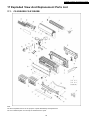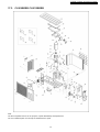
1
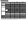
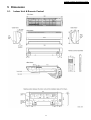
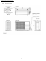
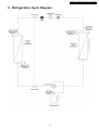
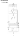
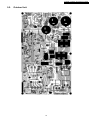
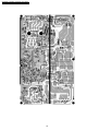
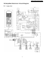
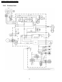
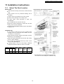
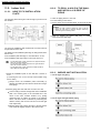
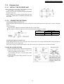
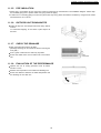
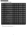
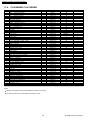
Order No: MAC0510072C2
Air Conditioner
CS-E9EKEB CU-E9EKEB
CS-E12EKEB CU-E12EKEB
CONTENTS
Page
Page
1 Safety Precautions
3
6 Refrigeration Cycle Diagram
13
2 Specification
5
7 Block Diagram
14
2.1. CS-E9EKEB CU-E9EKEB
5
8 Wiring Diagram
15
2.2. CS-E12EKEB CU-E12EKEB
7
8.1. CS-C9EKEB CS-C12EKEB
15
9
8.2. CU-C9EKEB CU-C12EKEB
16
3 Features
3.1. Super Air Purifying System with SUPER alleru-buster
9
9 Printed Circuit Board
17
3.2. Ion Freshener
9
9.1. Indoor Unit
17
3.3. Super Quiet
9
9.2. Outdoor Unit
19
3.4. Powerful Heating And Top-class Energy Effciency
4 Location of controls and components
9
10 Simplified Electronic Circuit Diagram
21
10
10.1. Indoor Unit
21
4.1. Indoor Unit
10
10.2. Outdoor Unit
22
4.2. Outdoor Unit
10
11 Installation Instructions
23
4.3. Remote Control
10
11.1. Select The Best Location
23
11
11.2. Indoor Unit
24
5.1. Indoor Unit & Remote Control
11
11.3. Outdoor Unit
27
5.2. Outdoor Unit
12
5 Dimension
© 2005 Panasonic HA Air-Conditioning (M) Sdn Bhd
(11969-T). All rights reserved. Unauthorized copying
and distribution is a violation of law.
CS-E9EKEB CU-E9EKEB / CS-E12EKEB CU-E12EKEB
12 Operation And Control
30
15.1. Indoor Electronic Controller and Control Board
41
12.1. Basic Function
30
15.2. Indoor Cross Flow Fan and Fan Motor
43
12.2. Protection Control
35
15.3. Outdoor Propeller Fan and Fan Motor
45
13 Servicing Mode
37
16 Technical Data
47
13.1. Auto Switch Operation
37
16.1. CS-E9EKEB CU-E9EKEB
47
13.2. Indicator Panel
37
16.2. CS-E12EKEB CU-E12EKEB
53
16.3. Sensible Capacity Chart
58
14 Troubleshooting Guide
14.1. Refrigeration Cycle System
38
17 Exploded View And Replacement Parts List
38
14.2. Relationship Between The Condition Of The Air
59
17.1. CS-E9EKEB CS-E12EKEB
59
39
17.2. CS-E9EKEB CS-E12EKEB
60
14.3. Breakdown Self Diagnosis Function
39
17.3. CU-E9EKEB CU-E12EKEB
61
14.4. Error Codes Table
40
17.4. CU-E9EKEB CU-E12EKEB
62
Conditioner And Pressure And Electric Current
15 Disassembly and Assembly Instructions
41
2
CS-E9EKEB CU-E9EKEB / CS-E12EKEB CU-E12EKEB
1 Safety Precautions
• Read the following “SAFETY PRECAUTIONS” carefully before perform any servicing.
• Electrical work must be installed or serviced by a licensed electrician. Be sure to use the correct rating of the power plug and
main circuit for the model installed.
• The caution items stated here must be followed because these important contents are related to safety. The meaning of each
indication used is as below.
Incorrect installation or servicing due to ignoring of the instruction will cause harm or damage, and the seriousness is classified
by the following indications.
This indication shows the possibility of causing death or serious injury.
This indication shows the possibility of causing injury or damage to properties.
• The items to be followed are classified by the symbols:
This symbol denotes item that is PROHIBITED from doing.
• Carry out test running to confirm that no abnormality occurs after the servicing. Then, explain to user the operation, care and
maintenance as stated in instructions. Please remind the customer to keep the operating instructions for future reference.
1. Engage dealer or specialist for installation and servicing. If installation or servicing done by the user is defective, it will cause water
leakage, electrical shock or fire.
2. Install according to this installation instruction strictly. If installation is defective, it will cause water leakage, electrical shock or fire.
3. Use the attached accessories parts and specified parts for installation and servicing. Otherwise, it will cause the set to fall, water
leakage, fire or electrical shock.
4. Install at a strong and firm location which is able to withstand the set’s weight. If the strength is not enough or installation is not properly
done, the set will drop and cause injury.
5. For electrical work, follow the local national wiring standard, regulation and the installation instruction. An independent circuit and single
outlet must be used. If electrical circuit capacity is not enough or defect found in electrical work, it will cause electrical shock or fire.
6. Use the specified cable and connect tightly for indoor/outdoor connection. Connect tightly and clamp the cable so that no external force
will be acted on the terminal. If connection or fixing is not perfect, it will cause heat-up or fire at the connection.
7. Wire routing must be properly arranged so that control board cover is fixed properly. If control board cover is not fixed perfectly, it will
cause heat-up at connection point of terminal, fire or electrical shock.
8. When connecting the piping, do not allow air or any substances other than the specified refrigerant to enter the
refrigeration cycle. Otherwise, this may lower the capacity, cause abnormally high pressure in the refrigeration cycle, and
possibly result in explosion and injury.
9. Thickness of copper pipes used must be more than 0.8 mm. Never use copper pipes thinner than 0.8 mm.
10. It is desirable that the amount of residual oil is less than 40 mg/10 m.
11. Do not modify the length of the power supply cord or use of the extension cord, and do not share the single outlet with
other electrical appliances. Otherwise, it will cause fire or electrical shock.
3
CS-E9EKEB CU-E9EKEB / CS-E12EKEB CU-E12EKEB
1. The equipment must be earthed. It may cause electrical shock if grounding is not perfect.
2. Do not install the unit at place where leakage of flammable gas may occur. In case gas leaks and accumulates at
surrounding of the unit, it may cause fire.
3. Carry out drainage piping as mentioned in installation instructions. If drainage is not perfect, water may enter the room and damage the
furniture.
4. Pb free solder has a higher melting point than standard solder; typically the melting point is 50 - 70°F (30 - 40°C) higher. Please use a
high temperature soldering iron. In case of the soldering iron with temperature control, please set it to 700 20°F (370 10°C).
Pb free solder will tend to splash when heated too high (about 1100°F/600°C).
1. Selection of the installation location. Select an installation location which is rigid and strong enough to support or hold the unit, and select
a location for easy maintenance.
2. Power supply connection to the air conditioner. Connect the power supply cord of the air conditioner to the mains using one of the
following methods. Power supply point shall be the place where there is ease for access for the power disconnection in case of
emergency.
In some countries, permanent connection of this room air conditioner to the power supply is prohibited.
1. Power supply connection to the receptacle using a power plug. Use an approved power plug with earth pin for the connection to the
socket.
2. Power supply connection to a circuit breaker for the permanent connection. Use an approved circuit breaker for the permanent
connection. It must be a double pole switch with a minimum 3.5 mm contact gap.
3. Do not release refrigerant during piping work for installation, servicing, reinstallation and during repairing a refrigeration parts. Take care
of the liquid refrigerant, it may cause frostbite.
4. Installation work. It may need two people to carry out the installation work.
5. Do not install this appliance in a laundry room or other location where water may drip from the ceiling, etc.
4
CS-E9EKEB CU-E9EKEB / CS-E12EKEB CU-E12EKEB
2 Specification
2.1.
CS-E9EKEB CU-E9EKEB
Unit
CS-E9EKEB
CU-E9EKEB
Performance Test Condition
EUROVENT
Cooling Capacity
kW
kcal/h
2.60 (0.60 - 3.00)
2,240 (520 - 2,580)
Heating Capacity
kW
kcal/h
3.60 (0.60 - 5.40)
3,100 (520 - 4,640)
Moisture Removal
l/h
Pint/h
1.6
3.4
ø
V
Hz
Single
230
50
Power Source (Phase, Voltage, Cycle)
Airflow Method
OUTLET
SIDE VIEW
TOP VIEW
Cooling; 6.2 (220)
Heating; 6.6 (230)
Cooling; 7.9 (280)
Heating; 8.6 (300)
Cooling; 9.6 (340)
Heating; 10.5 (370)
Cooling; 9.9 (350)
Heating; 10.8 (380)
—
INTAKE
Air Volume
Lo
m3/min (cfm)
Me
m3/min (cfm)
Hi
m3/min (cfm)
SHi
m3/min (cfm)
—
Cooling; 29.8 (1,050)
—
dB (A)
Cooling; High 39, Low 26
Heating; High 40, Low 27
Cooling; 46
Heating; 47
Power level dB
Cooling; High 50
Heating; High 51
Cooling; High 59
Heating; High 60
Noise Level
Electrical Data
Input
W
Cooling; 590 (120 - 750)
Heating; 845 (115 - 1,360)
Running Current
A
Cooling; 2.9
Heating; 4.0
EER
COP
Starting Current
Piping Connection Port
(Flare piping)
Pipe Size
(Flare piping)
Drain
Inner diameter
Hose
Length
W/W (kcal/hw)
W/W (kcal/hw)
A
inch
inch
inch
inch
mm
m
5
Cooling; 4.41 (3.80)
Heating; 4.26 (3.67)
4.0
G ; Half Union 3/8”
G ; 3-way valve 3/8”
L ; Half Union 1/4”
L ; 2-way valve 1/4”
G (gas side) ; 3/8”
G (gas side) ; 3/8”
L (liquid side) ; 1/4”
L (liquid side) ; 1/4”
16
—
0.65
—
CS-E9EKEB CU-E9EKEB / CS-E12EKEB CU-E12EKEB
Unit
m
Power Cord Length
Number of core-wire
Dimensions
Height
Width
Depth
Net Weight
Compressor
Motor
Rated
Fan Motor
inch (mm)
inch (mm)
inch (mm)
lb (kg)
Type
Type
Output
Type
Material
Type
Input
Rate Output
Lo (Cool/Heat)
Me (Cool/Heat)
Hi (Cool/Heat)
SHi (Cool/Heat)
Motor
Fan Speed
Heat Exchanger
W
W
W
rpm
rpm
rpm
rpm
Description
Tube material
Fin material
Fin Type
Row / Stage
FPI
Size (W × H × L)
Refrigerant Control Device
Refrigeration Oil
Refrigerant (R410A)
Thermostat
Protection Device
Air Filter
mm
(cm3)
g (oz)
Material
Style
CS-E9EKEB
CU-E9EKEB
1.8
—
(1.5mm2)
—
11 - 1/32 (280)
21 - 1/4 (540)
31 - 15/32 (799)
30 - 23/32 (780)
7 - 7/32 (183)
11 - 3/8 (289)
20 (9.0)
77 (35)
—
Hermetic Motor
—
Brushless (4-pole)
—
750
Cross-flow Fan
Propeller Fan
ASG20k1
P.P
Transistor (8-poles)
Induction (8-poles)
44.3
61.3
30
40
820/880
—
1,050/1,140
—
1,280/1,400
800/790
1,320/1,440
—
Evaporator
Condenser
Copper
Copper
Aluminium (Pre Coat)
Aluminium
Slit Fin
Corrugated Fin
(Plate fin configuration, forced draft)
2 / 15
2 / 24
21
17
610 × 315 × 25.4
718.4 × 504 × 36.4
689.8
—
Capillary Tube
—
RB68A (400)
—
930 (32.8)
Electronic Control
—
—
Electronic Control
P.P.
—
Honeycomb
• Specifications are subjected to change without prior notice for further improvement.
6
CS-E9EKEB CU-E9EKEB / CS-E12EKEB CU-E12EKEB
2.2.
CS-E12EKEB CU-E12EKEB
Unit
CS-E12EKEB
Performance Test Condition
CU-E12EKEB
EUROVENT
Cooling Capacity
kW
kcal/h
3.50 (0.60 - 4.00)
3,010 (520 - 3,440)
Heating Capacity
kW
kcal/h
4.80 (0.60 - 6.60)
4,130 (520 - 5,680)
Moisture Removal
l/h
Pint/h
2.0
4.2
ø
V
Hz
Single
230
50
Power Source (Phase, Voltage, Cycle)
Airflow Method
OUTLET
SIDE VIEW
TOP VIEW
Cooling; 6.9 (240)
Heating; 8.1 (290)
Cooling; 8.8 (310)
Heating; 9.7 (340)
Cooling; 10.7 (380)
Heating; 11.2 (400)
Cooling; 11.0 (390)
Heating; 11.6 (410)
—
INTAKE
Air Volume
Lo
m3/min (cfm)
Me
m3/min (cfm)
Hi
m3/min (cfm)
SHi
m3/min (cfm)
—
Cooling; 31.0 (1,090)
—
dB (A)
Cooling; High 42, Low 29
Heating; High 42, Low 33
Cooling; 48
Heating; 50
Power level dB
Cooling; High 53
Heating; High 53
Cooling; High 61
Heating; High 63
Noise Level
Electrical Data
Input
W
Cooling; 920 (120 - 1,180)
Heating; 1,260 (115 - 1,850)
Running Current
A
Cooling; 4.3
Heating; 5.8
EER
COP
Starting Current
W/W (kcal/hw)
W/W (kcal/hw)
A
inch
inch
inch
inch
mm
m
Cooling; 3.80 (3.27)
Heating; 3.81 (3.28)
5.8
G ; Half Union 1/2”
G ; 3-way valve 1/2”
L ; Half Union 1/4”
L ; 2-way valve 1/4”
G (gas side) ; 1/2”
G (gas side) ; 1/2”
L (liquid side) ; 1/4”
L (liquid side) ; 1/4”
16
—
0.65
—
1.8
—
(1.5mm2)
—
Piping Connection Port
(Flare piping)
Pipe Size
(Flare piping)
Drain
Inner diameter
Hose
Length
Power Cord Length
Number of core-wire
7
CS-E9EKEB CU-E9EKEB / CS-E12EKEB CU-E12EKEB
Dimensions
Net Weight
Compressor
Motor
Rated
Fan Motor
Motor
Fan Speed
Heat Exchanger
Unit
inch (mm)
inch (mm)
inch (mm)
lb (kg)
Height
Width
Depth
Type
Type
Output
Type
Material
Type
Input
Rate Output
Lo (Cool/Heat)
Me (Cool/Heat)
Hi (Cool/Heat)
SHi (Cool/Heat)
W
W
W
rpm
rpm
rpm
rpm
Description
Tube material
Fin material
Fin Type
Row / Stage
FPI
Size (W × H × L)
Refrigerant Control Device
Refrigeration Oil
Refrigerant (R410A)
Thermostat
Protection Device
Air Filter
Material
Style
mm
(cm3)
g (oz)
CS-E12EKEB
CU-E12EKEB
11 - 1/32 (280)
21 - 1/4 (540)
31 - 15/32 (799)
30 - 23/32 (780)
7 - 7/32 (183)
11 - 3/8 (289)
20 (9.0)
79 (36)
—
Hermetic Motor
—
Brushless (4-pole)
—
750
Cross-flow Fan
Propeller Fan
ASG20k1
P.P
Transistor (8-poles)
Induction (8-poles)
44.3
65.9
30
40
910/1,080
—
1,165/1,290
—
1,420/1,500
840 / 820
1,460/1,540
—
Evaporator
Condenser
Copper
Copper
Aluminium (Pre Coat)
Aluminium
Slit Fin
Corrugated Fin
(Plate fin configuration, forced draft)
2 / 15
2 / 24
21
17
610 × 315 × 25.4
718.4 × 504 × 36.4
689.8
—
Capillary Tube
—
RB68A (400)
—
970 (34.2)
Electronic Control
—
—
Electronic Control
P.P.
—
Honeycomb
• Specifications are subjected to change without prior notice for further improvement.
8
CS-E9EKEB CU-E9EKEB / CS-E12EKEB CU-E12EKEB
3 Features
3.1.
3.1.1.
Super Air Purifying System
with SUPER alleru-buster
3.2.
• Around 20,000 negative ions/cc are generated to freshen
the room. It’s like being next to a waterfall or in a forest.
Supersonic Air Purifying System
• The Supersonic Air Purifying System incorporated in the
indoor unit generates supersonic waves.
3.3.
• The system works in combination with the filter to collects
dust and dirt in the air for faster, more efficient air
purification.
3.1.2.
Ion Freshener
Super Quiet
• The indoor unit operates at a whisper-quiet 26dB. You can
also press the Quiet Mode button to lower the operating
noise 3 dB. We’ve reduced the noise of the outdoor unit,
too, with the e-scroll Compressor and 2-Wing Fan. You can
run the air conditioner at night and enjoy a deeper, more
comfortable sleep, and without bothering your neighbours.
SUPER alleru-buster filter
3.4.
• The SUPER alleru-buster filter combines three effects in
one — anti-allergen, anti-virus, anti-bacteria protection — to
keep room air clean and healthful.
9
Powerful Heating And Topclass Energy Effciency
CS-E9EKEB CU-E9EKEB / CS-E12EKEB CU-E12EKEB
4 Location of controls and components
4.1.
Indoor Unit
4.2.
Outdoor Unit
4.3.
Remote Control
10
CS-E9EKEB CU-E9EKEB / CS-E12EKEB CU-E12EKEB
5 Dimension
5.1.
Indoor Unit & Remote Control
11
CS-E9EKEB CU-E9EKEB / CS-E12EKEB CU-E12EKEB
5.2.
Outdoor Unit
12
CS-E9EKEB CU-E9EKEB / CS-E12EKEB CU-E12EKEB
6 Refrigeration Cycle Diagram
13
CS-E9EKEB CU-E9EKEB / CS-E12EKEB CU-E12EKEB
7 Block Diagram
14
CS-E9EKEB CU-E9EKEB / CS-E12EKEB CU-E12EKEB
8 Wiring Diagram
8.1.
CS-C9EKEB CS-C12EKEB
15
CS-E9EKEB CU-E9EKEB / CS-E12EKEB CU-E12EKEB
8.2.
CU-C9EKEB CU-C12EKEB
16
CS-E9EKEB CU-E9EKEB / CS-E12EKEB CU-E12EKEB
9 Printed Circuit Board
9.1.
Indoor Unit
17
CS-E9EKEB CU-E9EKEB / CS-E12EKEB CU-E12EKEB
18
CS-E9EKEB CU-E9EKEB / CS-E12EKEB CU-E12EKEB
9.2.
Outdoor Unit
19
CS-E9EKEB CU-E9EKEB / CS-E12EKEB CU-E12EKEB
20
CS-E9EKEB CU-E9EKEB / CS-E12EKEB CU-E12EKEB
10 Simplified Electronic Circuit Diagram
10.1. Indoor Unit
21
CS-E9EKEB CU-E9EKEB / CS-E12EKEB CU-E12EKEB
10.2. Outdoor Unit
22
CS-E9EKEB CU-E9EKEB / CS-E12EKEB CU-E12EKEB
11 Installation Instructions
11.1. Select The Best Location
INDOOR UNIT
Indoor/Outdoor Unit Installation Diagram
• There should not be any heat source or steam near the
unit.
• There should not be any obstacles blocking the air
circulation.
• A place where air circulation in the room is good.
• A place where drainage can be easily done.
• A place where
consideration.
noise
prevention
is
taken
into
• Do not install the unit near the door way.
• Ensure the spaces indicated by arrows from the wall,
ceiling, fence or other obstacles.
• Recommended installation height for indoor unit shall be
at least 2.5 m.
OUTDOOR UNIT
• If an awning is built over the unit to prevent direct
sunlight or rain, be careful that heat radiation from the
condenser is not obstructed.
• There should not be any animal or plant which could be
affected by hot air discharged.
• Keep the spaces indicated by arrows from wall, ceiling,
fence or other obstacles.
• Do not place any obstacles which may cause a short
circuit of the discharged air.
• If piping length is over the rated length, additional
refrigerant should be added as shown in the table.
Model
Piping size Rated
Max.
Gas Liquid Length Elevation
(m)
(m)
E9EK
E12EK
3/8”
1/2”
1/4”
1/4”
7.5
7.5
5
5
Max.
Piping
Length
(m)
15
15
Additional
Refrigerant
(g/m)
20
20
• This illustration is for explanation purposes only.
The indoor unit will actually face a different way.
23
CS-E9EKEB CU-E9EKEB / CS-E12EKEB CU-E12EKEB
11.2.2. TO DRILL A HOLE IN THE WALL
AND INSTALL A SLEEVE OF
PIPING
11.2. Indoor Unit
11.2.1. HOW TO FIX INSTALLATION
PLATE
1. Insert the piping sleeve to the hole.
The mounting wall is strong and solid enough to prevent it from
the vibration.
2. Fix the bushing to the sleeve.
3. Cut the sleeve until it extrudes about 15 mm from the wall.
Caution
When the wall is hollow, please be sure to use the
sleeve for tube ass’y to prevent dangers caused by
mice biting the connecting cable.
4. Finish by sealing the sleeve with putty or caulking
compound at the final stage.
The centre of installation plate should be at more than 450 mm
at right and left of the wall.
The distance from installation plate edge to ceiling should more
than 67 mm.
From installation plate left edge to unit’s left side is 74 mm.
From installation plate right edge to unit’s right is 94 mm.
: For left side piping, piping connection for liquid should be
about 15 mm from this line.
: For left side piping, piping connection for gas should be
about 45 mm from this line.
: For left side piping, piping connection cable should be
about 800 mm from this line.
11.2.3. INDOOR UNIT INSTALLATION
1. Mount the installation plate on the wall with 5 screws or
more.
(If mounting the unit on the concrete wall consider using
anchor bolts.)
1. For the right rear piping
• Always mount the installation plate horizontally by
aligning the marking-off line with the thread and using a
level gauge.
2. Drill the piping plate hole with ø70 mm hole-core drill.
• Line according to the left and right side of the installation
plate. The meeting point of the extended line is the
centre of the hole. Another method is by putting
measuring tape at position as shown in the diagram
above. The hole centre is obtained by measuring the
distance namely 150 mm and 125 mm for left and right
hole respectively.
2. For the right and right bottom piping
• Drill the piping hole at either the right or the left and the
hole should be slightly slanted to the outdoor side.
24
CS-E9EKEB CU-E9EKEB / CS-E12EKEB CU-E12EKEB
3. For the embedded piping
(This can be used for left rear piping & left bottom piping also.)
25
CS-E9EKEB CU-E9EKEB / CS-E12EKEB CU-E12EKEB
11.2.4. CONNECT THE CABLE TO THE
INDOOR UNIT
1. The inside and outside connecting cable can be connected
without removing the front grille.
2. Connecting cable between indoor unit and outdoor unit
shall be approved polychloroprene sheathed 4 × 1.5 mm2
flexible cord, type designation 245 IEC 57 or heavier cord.
• Ensure the color of wires of outdoor unit and the
terminal Nos. are the same to the indoor’s respectively.
• Earth lead wire shall be longer than the other lead wires
as shown in the figure for the electrical safety in case of
the slipping out of the cord from the anchorage.
• Secure the cable onto the control board with the holder
(clamper).
11.2.5. INSTALLATION OF SUPER ALLERU-BUSTER FILTER
1. Open the front panel.
2. Remove the air filter.
3. Remove Supersonic air purifying device.
4. Open the Supersonic air purifying device frame.
5. Insert the super alleru-buster filter and close the Supersonic
air purifying device frame as show in illustration at right.
11.2.6. HOW TO TAKE OUT FRONT GRILLE
Please follow the steps below to take out front grille if necessary such as when servicing.
1. Set the vertical airflow direction louvers to the horizontal position.
2. Slide down the 2 caps on the front grille as shown in the illustration below, and then remove the 2 mounting screws.
3. Pull the lower section of the front grille towards you to remove the front grille.
When reinstalling the front grille, first set the vertical
airflow direction louvers to the horizontal position and
then carry out above steps 2 - 3 in the reverse order.
26
CS-E9EKEB CU-E9EKEB / CS-E12EKEB CU-E12EKEB
11.3. Outdoor Unit
11.3.1. INSTALL THE OUTDOOR UNIT
• After selecting the best location, start installation according
to Indoor/Outdoor Unit Installation Diagram.
1. Fix the unit on concrete or rigid frame firmly and horizontally
by bolt nut (ø10 mm).
2. When installing at roof, please consider strong wind and
earthquake. Please fasten the installation stand firmly with
bolt or nails.
11.3.2. CONNECTING THE PIPING
Connecting The Piping To Indoor Unit
Please make flare after inserting flare nut (locate at joint portion of tube assembly) onto the copper pipe. (In case of using long
piping)
Connect the piping
• Align the center of piping and sufficiently tighten the flare nut with fingers.
• Further tighten the flare nut with torque wrench in specified torque as stated in the table.
MODEL
E9EK
E12EK
Piping size (Torque)
Gas
Liquid
3/8” (42 N.m)
1/4” (18 N.m)
1/2” (55 N.m)
1/4” (18 N.m)
Connecting The Piping To Outdoor Unit
Decide piping length and then cut by using pipe cutter. Remove burrs from cut edge. Make flare after inserting the flare nut
(located at valve) onto the copper pipe.
Align center of piping to valves and then tighten with torque wrench to the specified torque as stated in the table.
CUTTING AND FLARING THE PIPING
1. Please cut using pipe cutter and then remove the burrs.
2. Remove the burrs by using reamer. If burrs is not
removed, gas leakage may be caused.
Turn the piping end down to avoid the metal powder
entering the pipe.
3. Please make flare after inserting the flare nut onto the
copper pipes.
27
CS-E9EKEB CU-E9EKEB / CS-E12EKEB CU-E12EKEB
11.3.3. EVACUATION OF THE EQUIPMENT
WHEN INSTALLING AN AIR CONDITIONER, BE SURE TO EVACUATE THE AIR INSIDE THE INDOOR UNIT AND PIPES in the
following procedure.
1. Connect a charging hose with a push pin to the Low side of a charging set and the service port of the 3-way valve.
• Be sure to connect the end of the charging hose with the push pin to the service port.
2. Connect the center hose of the charging set to a vacuum pump with check valve, or vacuum pump and vacuum pump adaptor.
3. Turn on the power switch of the vacuum pump and make sure that the needle in the gauge moves from 0 cmHg (0 MPa) to
-76 cmHg (-0.1 MPa). Then evacuate the air approximately ten minutes.
4. Close the Low side valve of the charging set and turn off the vacuum pump. Make sure that the needle in the gauge does not
move after approximately five minutes.
Note: BE SURE TO FOLLOW THIS PROCEDURE IN ORDER TO AVOID REFRIGERANT GAS LEAKAGE.
5. Disconnect the charging hose from the vacuum pump and from the service port of the 3-way valve.
6. Tighten the service port caps of the 3-way valve at a torque of 18 N.m with a torque wrench.
7. Remove the valve caps of both of the 2-way valve and 3-way valve. Position both of the valves to “OPEN” using a hexagonal
wrench (4 mm).
8. Mount valve caps onto the 2-way valve and the 3-way valve.
• Be sure to check for gas leakage.
CAUTION
• If gauge needle does not move from 0 cmHg (0 MPa) to -76 cmHg (-0.1 MPa), in step
above take the following measure:
• If the leak stops when the piping connections are tightened further, continue working from step
.
• If the leak does not stop when the connections are retightened, repair the location of leak.
• Do not release refrigerant during piping work for installation and reinstallation. Take care of the liquid refrigerant, it may cause
frostbite.
11.3.4. CONNECT THE CABLE TO THE OUTDOOR UNIT
(FOR DETAIL REFER TO WIRING DIAGRAM AT UNIT)
1. Remove the control board cover from the unit by loosening the screw.
2. Connecting cable between indoor unit and outdoor unit shall be approved polychloroprene sheathed 4 × 1.5 mm2 flexible cord,
type designation 245 IEC 57 or heavier cord.
3. Secure the cable onto the control board with the holder (clamper).
4. Attach the control board cover back to the original position with the screw.
28
CS-E9EKEB CU-E9EKEB / CS-E12EKEB CU-E12EKEB
11.3.5. PIPE INSULATION
1. Please carry out insulation at pipe connection portion as mentioned in Indoor/Outdoor Unit Installation Diagram. Please wrap
the insulated piping end to prevent water from going inside the piping.
2. If drain hose or connecting piping is in the room (where dew may form), please increase the insulation by using POLY-E FOAM
with thickness 6 mm or above.
11.3.6. OUTDOOR UNIT DRAIN WATER
• Water will drip from the basepan hole area during defrost
function.
To avoid water dripping, do not stand or place objects at
this area.
11.3.7. CHECK THE DRAINAGE
• Open front panel and remove air filters.
(Drainage checking can be carried out without removing the
front grille.)
• Pour a glass of water into the drain tray-styrofoam.
• Ensure that water flows out from drain hose of the indoor
unit.
11.3.8. EVALUATION OF THE PERFORMANCE
• Operate the unit at cooling operation mode for fifteen
minutes or more.
• Measure the temperature of the intake and discharge air.
• Ensure the difference between the intake temperature and
the discharge is more than 8°C.
29
CS-E9EKEB CU-E9EKEB / CS-E12EKEB CU-E12EKEB
12 Operation And Control
12.1. Basic Function
Inverter control, which equipped with a microcomputer in determining the most suitable operating mode as time passes,
automatically adjusts output power for maximum comfort always. In order to achieve the suitable operating mode, the
microcomputer maintains the set temperature by measuring the temperature of the environment and performing temperature
shifting. The compressor at outdoor unit is operating following the frequency instructed by the microcomputer at indoor unit that
judging the condition according to internal setting temperature and intake air temperature.
12.1.1. Internal Setting Temperature
Once the operation starts, remote control setting temperature will be taken as base value for temperature shifting processes.
These shifting processes are depending on the air conditioner settings and the operation environment. The final shifted value
will be used as internal setting temperature and it is updated continuously whenever the electrical power is supplied to the unit.
12.1.2. Airflow Direction
1. There are two types of airflow, vertical airflow (directed by horizontal vane) and horizontal airflow (directed by vertical vanes).
2. Control of airflow direction can be automatic (angles of direction is determined by operation mode, heat exchanger temperature
and intake air temperature) and manual (angles of direction can be adjusted using remote control).
12.1.2.1. Vertical Airflow
Operation Mode
Airflow Direction
1
Heating
Cooling, Soft Dry and Ion
Mode Judgment in Auto
Auto with Heat Exchanger
Temperature
Manual
Auto
Manual
Auto
Manual
A
B
C
D
Upward fix
Downward fix
Upward fix
Downward fix
3
8
8
Vane Angle (°)
2
3
4
3
64
3
3
17
33
49
8 ~ 36
15
22
30
8
15
22
30
5
63
36
36
1. Automatic vertical airflow direction can be set using remote control; the vane swings up and down within the angles as stated
above. For heating mode operation, the angle of the vane depends on the indoor heat exchanger temperature as Figure 1
below. When the air conditioner is stopped using remote control, the vane will shift to close position.
2. Manual vertical airflow direction can be set using remote control; the angles of the vane are as stated above and the positions
of the vane are as Figure 2 below. When the air conditioner is stopped using remote control, the vane will shift to close position.
30
CS-E9EKEB CU-E9EKEB / CS-E12EKEB CU-E12EKEB
12.1.2.2. Horizontal Airflow
1. Automatic horizontal airflow direction can be set using remote control; the vane swings left and right within the angles as stated
below. For heating mode operation, the angle of the vane depends on the indoor heat exchanger temperature as Figure 1
below.
Operation Mode
Heating, with heat exchanger temperature
Vane Angle (°)
65 ~ 115
90
65 ~ 115
A
B
Cooling, Soft Dry and Ion
2. Manual horizontal airflow direction can be set using remote control; the angles of the vane are as stated below and the positions
of the vane are as Figure 2 above.
Pattern
Airflow Direction
Patterns at Remote
Control
1
2
3
4
5
Vane Angle (°)
90
65
78
102
115
12.1.3. Quiet operation (Cooling Mode/Cooling area of Dry Mode)
A. Purpose
To provide quiet cooling operation compare to normal operation.
B. Control condition
a. Quiet operation start condition
• When “quiet” button at remote control is pressed.
Quiet LED illuminates.
b. Quiet operation stop condition
1. When one of the following conditions is satisfied, quiet operation stops:
a. Powerful button is pressed.
b. Stop by OFF/ON switch.
c. Timer “off” activates.
d. Quiet button is pressed again.
31
CS-E9EKEB CU-E9EKEB / CS-E12EKEB CU-E12EKEB
2. When quiet operation is stopped, operation is shifted to normal operation with previous setting.
3. When fan speed is changed, quiet operation is shifted to quiet operation of the new fan speed.
4. When operation mode is changed, quiet operation is shifted to quiet operation of the new mode.
5. During quiet operation, if timer “on” activates, quiet operation maintains.
6. After off, when on back, quiet operation is not memorised.
C. Control contents
1. Fan speed is changed from normal setting to quiet setting of respective fan speed.
This is to reduce sound of Hi, Me, Lo for 3dB.
2. Fan speed for quiet operation is -1 step from setting fan speed.
12.1.3.1. Quiet operation (Heating)
A. Purpose
To provide quiet heating operation compare to normal operation.
B. Control condition
a. Quiet operation start condition
• When “quiet” button at remote control is pressed.
Quiet LED illuminates.
b. Quiet operation stop condition
1. When one of the following conditions is satisfied, quiet operation stops:
a. Powerful button is pressed.
b. Stop by OFF/ON switch.
c. Timer “off” activates.
d. Quiet button is pressed again.
2. When quiet operation is stopped, operation is shifted to normal operation with previous setting.
3. When fan speed is changed, quiet operation is shifted to quiet operation of the new fan speed.
4. When operation mode is changed, quiet operation is shifted to quiet operation of the new mode, except fan only mode.
5. During quiet operation, if timer “on” activates, quiet operation maintains.
6. After off, when on back, quiet operation is not memorised.
C. Control contents
a. Fan Speed manual
1. Fan speed is changed from normal setting to quiet setting of respective fan speed.
This is to reduce sound of Hi, Me, Lo for 3dB.
2. Fan speed for quiet operation is -1 step from setting fan speed.
3. Fan Speed Auto
Indoor FM RPM depends on pipe temp sensor of indoor heat exchanger.
32
CS-E9EKEB CU-E9EKEB / CS-E12EKEB CU-E12EKEB
12.1.4. Powerful Mode Operation
When the powerful mode is selected, the internal setting temperature will shift to achieve the setting temperature quickly.
(a) Cooling Operation
(b) Soft Dry Operation
(c) Heating Operation
12.1.5. ON Timer Control
ON timer can be set using remote control, the unit with timer set will start operate earlier than the setting time. This is to provide
a comfortable environment when reaching the set ON time.
60 minutes before the set time, indoor (at fan speed of Lo-) and outdoor fan motor start operate for 30 seconds to determine the
indoor intake air temperature and outdoor air temperature in order to judge the operation starting time.
From the above judgment, the decided operation will start operate earlier than the set time as shown below.
12.1.6. OFF Timer Control
OFF timer can be set using remote control, the unit with timer set will stop operate at set time.
33
CS-E9EKEB CU-E9EKEB / CS-E12EKEB CU-E12EKEB
12.1.7. Auto Restart Control
1. When the power supply is cut off during the operation of air conditioner, the compressor will re-operate within three to four
minutes (there are 10 patterns between 2 minutes 58 seconds and 3 minutes 52 seconds to be selected randomly) after power
supply resumes.
2. This type of control is not applicable during ON/OFF Timer setting.
12.1.8. Ionizer Operation
Purpose
To provide fresh air effect to users by discharging minus ion to air.
Control Condition
a. Ionizer Only Operation.
1. When air-conditioner unit is at “OFF” condition (standby) and ION operation button at remote control is pressed.
Fan & ionizer on, ION LED illuminates, but power LED maintain off. (1 → 2)
However, fan speed can be adjusted later by customer during this operation.
Airflow direction (Horizontal Vane) control:
Follow vane direction control at cooling mode.
Horizontal vane can be changed by customer during ion only operation.
b. Operation Mode + Ionizer Operation.
1. Ionising Operation Start Condition
When air conditioner unit is in “ON” condition (Heat, Cool, Dry, Auto mode) and ION operation button at remote control is
pressed. Ionizer on & ION LED illuminates. (3 → 4)
Power LED also illuminates.
2. Ionising Operation Stop Condition
When one of the following condition is satisfied, ION operation stops.
a. Stopped by ON/OFF switch.
b. Timer OFF activates.
c. ION feedback signal shows error.
3. Ionizer operation status is not memorised by micon. After OFF, when operation is “ON” again, air conditioner operates
without ionizer operation.
34
CS-E9EKEB CU-E9EKEB / CS-E12EKEB CU-E12EKEB
12.2. Protection Control
12.2.1. Time Delay Safety Control
• Compressor will not start for three minutes after stop of the operation.
12.2.2. 30 Seconds Forced Operation
• Once compressor starts the operation, it will not stop its operation for 30 seconds. However, it can be stopped with the remote
controller or the Auto button on the indoor unit.
12.2.3. Total Running Current Control
1. When the total running current exceeds l1, compressor operation frequency is reduced. If it reaches below l1, the operation
frequency is increased. (But, up to programmed frequency.)
2. If total running current exceeds l2, compressor is stopped immediately.
3. If it happens three (3) times within 20 minutes, operation will be stopped and Timer LED blinks. (“F98” is activating.)
Cooling
Heating
Running current
l1
l2
l1
l2
CS-E9EKEB
3.7A
25.0A
5.9A
25.0A
CS-E12EKEB
5.8A
25.0A
8.2A
25.0A
12.2.4. IPM (Power transistor) Protection Control (DC Peak detection)
Abnormal Current Control
• If inverter load current (DC peak) exceeds a rated value, compressor will be stopped immediately. When the excess occurs
within 30 seconds after operation, it restarts in 1 minute and when after 30 seconds, restarts in 2 minutes.
• If the excess continuously occurs 7 times within 30 minutes after compressor starts, the unit will be stopped and timer LED on
the indoor unit will be blinking. (“F99” is to be confirmed.)
IPM Overheating Prevention Control
• If temperature of IPM exceeds 103°C, compressor will be stopped. It will restart in 2 minutes. Temperature for restarting: 90°C.
• If the excess occurs 4 times within 30 minutes after compressor starts, the compressor will be stopped and timer LED on the
indoor unit will be blinking. (“F96” is to be confirmed.)
12.2.5. Compressor Overheating Prevention Control
1. If discharge pipe temperature exceeds 100°C, compressor power will be limited.
2. If discharge pipe temperature exceeds 112°C, compressor will be stopped.
3. If the above excess occurs 4 times per 10 minutes, timer LED will be blinking. (“F97” is to be confirmed.)
12.2.6. Outdoor High Pressure Prevention Control (Cooling and Dry operations)
1. If outdoor heat exchanger temperature exceeds 63°C in cooling or dry operation, compressor will be stopped.
2. Timer LED is not blinking. (“F95” is memorized, then.)
12.2.7. Compressor Protection Control (Refrigeration Cycle Abnormality)
In cooling and Dry operations
1. When compressor is operated continuously for 5 minutes in the maximum cooling power: a running current of 0.7 - 1.4A and
“[Indoor intake air temperature] - [Indoor heat exchanger temperature]” < 4°C, compressor will be stopped.
2. If the above excess occurs twice for 20 minutes, timer LED is to be blinking. (“F91” is to be confirmed.)
In Heating operation
1. When compressor is operated continuously for 5 minutes in the rated heating power: a running current of 0.7 - 1.4A and “[Indoor
heat exchanger temperature] - [Indoor intake air temperature]” < 5°C, compressor will be stopped.
2. If the above excess occurs twice for 20 minutes, timer LED is to be blinking. (“F91” is to be confirmed.)
35
CS-E9EKEB CU-E9EKEB / CS-E12EKEB CU-E12EKEB
12.2.8. Four-way Valve Operation Detection Control (Switching Abnormality between
Cooling and Heating)
In Cooling operation
1. When indoor heat exchanger temperature exceeds 45°C in 4 minutes after compressor starts, compressor will be stopped.
2. If the above excess occurs 4 times per 30 minutes, timer LED is to be blinking. (“F11” is to be confirmed.)
In Heating operation
1. When indoor heat exchanger temperature is below 0°C in 4 minutes after compressor starts, compressor will be stopped.
2. If the above excess occurs 4 times per 30 minutes, timer LED is to be blinking. (“F11” is to be confirmed.)
12.2.9. Anti-Freezing Control (Cooling and Dry operations)
Limit of Cooling power
1. When temperature of indoor heat exchanger is below 5°C, operating frequency will be decreased.
2. When temperature of indoor heat exchanger exceeds 7°C, operating frequency will be increased. (But, up to programmed
frequency.)
3. When temperature of indoor heat exchanger is below 0°C continuously for 6 minutes, compressor will be stopped.
4. Timer LED is not blinking. (“F99” is memorized, then.)
Limit of Indoor fan speed
• When temperature of indoor heat exchanger is below 6°C (2°C at Dry) continuously for 6 minutes, indoor fan speed will be
increased by 50 rpm.
12.2.10. Outdoor Air Temperature Control
In Cooling and Dry operations
1. When outdoor air temperature is below 25°C, the maximum power will be limited up to about 80 - 100% of the rated power.
2. When outdoor air temperature is below 18°C, the maximum power will be limited up to about 50 - 100% of the rated power.
3. When outdoor air temperature is below 11°C, the maximum power will be limited up to about 26 - 81% of the rated power.
12.2.11. Indoor Intake Air Temperature Control (Heating operation)
1. When indoor air temperature is 35°C or more, the maximum power will be limited up to the rated power.
2. When fan speed is set at “Lo” and intake air temperature is below 21°C, the maximum power will be limited up to the rated
power.
36
CS-E9EKEB CU-E9EKEB / CS-E12EKEB CU-E12EKEB
13 Servicing Mode
13.1. Auto Switch Operation
The below operations will be performed by pressing the “AUTO” switch.
1. AUTO OPERATION MODE
The Auto operation will be activated immediately once the Auto Switch is pressed.
2. TEST RUN OPERATION (FOR PUMP DOWN/SERVICING PURPOSE)
The Test Run operation will be activated if the Auto Switch is pressed continuously for more than 5 sec. A “beep” sound will
occur at the fifth sec., in order to identify the starting of Test Run operation.
3. REMOTE CONTROLLER RECEIVING SOUND ON/OFF
The ON/OFF of remote controller receiving sound can be change over by pressing the following step:
a. Release the Auto Switch after Test Run operation is activated.
b. Then, within 20 sec., after a., press Auto Switch for more than 5 sec.
A “beep” “beep” sound will occur at the fifth sec., then release the Auto Switch.
c. Within 20 sec. after b., press Auto Switch again. Everytime Auto Switch is pressed (within 20 sec. interval), remote
controller receiving sound status will be reversed between ON and OFF.
Long “beep” sound indicates that remote controller receiving sound is OFF.
Short “beep” sound indicates that remote controller receiving sound is ON.
13.2. Indicator Panel
LED
POWER
TIMER
QUIET
POWERFUL
ION
Color
Light ON
Light OFF
Green
Operation ON
Operation OFF
Orange
Timer Setting ON
Timer Setting OFF
Orange
Quiet Mode ON
Quiet Mode OFF
Orange
Powerful Mode ON
Powerful Mode OFF
Green
Ion Mode ON
Ion Mode OFF
ALLERGEN
BUSTER
Blue
Operation ON
Operation OFF
Note:
• If POWER LED is blinking, the possible operations of the unit are Hot Start, during Deice operation, operation mode
judgment, or ON timer sampling.
• If Timer LED is blinking, there is an abnormality operation occurs.
• If Ionizer, LED is blinking, there is an abnormality of Ionizer occurs.
37
CS-E9EKEB CU-E9EKEB / CS-E12EKEB CU-E12EKEB
14 Troubleshooting Guide
14.1. Refrigeration Cycle System
In order to diagnose malfunctions, make sure that there are no
electrical problems before inspecting the refrigeration cycle.
Such problems include insufficient insulation, problem with the
power source, malfunction of a compressor and a fan.
The normal outlet air temperature and pressure of the
refrigeration cycle depends on various conditions, the standard
values for them are shown in the table to the right.
38
CS-E9EKEB CU-E9EKEB / CS-E12EKEB CU-E12EKEB
14.2. Relationship Between The Condition Of The Air Conditioner And
Pressure And Electric Current
Cooling Mode
Condition of the air
conditoner
Low Pressure
High Pressure
Heating Mode
Electric current
during operation
Low Pressure
High Pressure
Electric current
during operation
Insufficient refrigerant
(gas leakage)
Clogged capillary tube
or Strainer
Short circuit in the
indoor unit
Heat radiation
deficiency of the
outdoor unit
Inefficient compression
• Carry on the measurements of pressure, electric current, and temperature fifteen minutes after an operation is started.
14.3. Breakdown Self Diagnosis Function
Once abnormality detected during operation, the unit will immediately stop its operation (Timer LED is blinking) and maximum of
three error codes (abnormality) will be saved in memory. The abnormality of the operation can be identified through the below
breakdown diagnosis method:
• Press “CHECK” button at remote controller continuously for more than five seconds to turn on the diagnosis mode, “H11” will
be displayed at remote controller.
• By pressing the TMER “
displayed.
” button once, next error code will be displayed; press “V” button once, previous error code will be
• If error code displayed matches the error code saved in unit memory (abnormality detected), “beep, beep, beep....” sounds will
be heard for 4 seconds and Power LED will light on. Otherwise, one “beep” sound is heard.
If “CHECK” button is press again or without any operation for 30 seconds, the diagnosis mode will turn off.
39
CS-E9EKEB CU-E9EKEB / CS-E12EKEB CU-E12EKEB
14.4. Error Codes Table
Diagnosis
display
Abnormality / Protection control
Abnormality
Judgement
Emergency
operation
Primary location to verify
H00
H11
No abnormality detected
Indoor / outdoor abnormal
communication
—
Normal operation
> 1 min after starting Indoor fan operation
operation
only
H12
H14
Connection capability rank abnormal
Indoor intake air temperature sensor
abnormality
Outdoor compressor temperature sensor
abnormality
Outdoor Current Transformer open
circuit
—
Continue for 5 sec.
—
—
Continue for 5 sec.
—
—
—
• Indoor / Outdoor PCB
—
• Intake air temperature sensor
(detective or disconnected)
• Compressor temperature sensor
(detective or disconnected)
• Outdoor PCB
—
—
• IPM (Power transistor) module
• Indoor PCB
—
Continue for 5 sec.
O
(Cooling only)
—
O
H15
H16
—
• Internal / external cable connections
H19
Indoor fan motor merchanism locked
H23
Indoor heat exchanger temperature
sensor abnormality
Ionizer breakdown
Outdoor intake air temperature sensor
abnormality
Outdoor heat exchanger temperature
sensor abnormality
Continue for 5 sec.
Continue for 5 sec.
O
Continue for 5 sec.
—
H33
H38
H97
Outdoor discharge air temperature
sensor abnormality
Indoor/Outdoor wrong connection
Indoor / outdoor mismatch (brand code)
Outdoor fan motor mechanism locked
—
—
2 times occurance
within 30 minutes
—
—
—
• Fan motor
• Heat exchanger temperature sensor
(defective or disconnected)
• Ionizer
• Outdoor temperature sensor
(defective or disconnected)
• Outdoor heat exchanger
temperature sensor (defective or
disconnected)
• Outdoor temperature sensor
(defective or disconnected)
• Indoor/Outdoor supply voltage
—
• Indoor PCB
H98
Indoor high pressure protection
—
—
• Fan motor
• Air filter dirty
H99
Indoor heat exchanger anti-freezing
protection
—
—
• Air circulation short circuit
• Insufficient refrigerant
F11
Cooling / Heating cycle changeover
abnormality
4 times occurance
within 30 minutes
—
• Air filter dirty
• 4-way valve
F90
PFC control
—
• V-coil
• Voltage at PFC
F91
Refrigeration cycle abnormality
F93
F95
Compressor rotation failure
Cool high pressure protection
F96
IPM (power transistor) overheating
protection
4 times occurance
within 10 minutes
2 times occurance
within 20 minutes
—
4 times occurance
within 20 minutes
—
H26
H27
H28
H30
—
—
• No refrigerant
(3-way valve is closed)
• Compressor
• Outdoor refrigerant circuit
—
• Excess refrigerant
—
• Improper heat radiation
F97
Outdoor compressor overheating
protection
4 times occurance
within 10 minutes
—
• IPM (Power transistor)
• Insufficient refrigerant
F98
Total running current protection
3 times occurance
within 20 minutes
—
• Compressor
• Excess refrigerant
F99
Outdoor Direct Current (DC) peak
detection
7 times occurance
continuously
—
• Improper heat radiation
• Outdoor PCB
• IPM (Power transistor)
• Compressor
Note:
“O” - Frequency measured and fan speed fixed.
The memory data of error code is erased when the power supply is cut off, or press the Auto Switch until “beep” sound heard
following by pressing the “RESET” button at remote controller.
Although operation forced to stop when abnormality detected, emergency operation is possible for certain errors (refer to Error
Codes Table) by using remote controller or Auto Switch at indoor unit. However, the remote controller signal receiving sound is
changed from one “beep” to four “beep” sounds.
40
CS-E9EKEB CU-E9EKEB / CS-E12EKEB CU-E12EKEB
15 Disassembly and Assembly Instructions
• Caution! When handling electronic controller, be careful of electrostatic discharge.
• Be sure to return the wiring to its original position.
• There are many high voltage components within the heat sink cover so never touch the interior during operation. Wait at least two
minutes after power has been turned off.
15.1. Indoor Electronic Controller and Control Board
41
CS-E9EKEB CU-E9EKEB / CS-E12EKEB CU-E12EKEB
42
CS-E9EKEB CU-E9EKEB / CS-E12EKEB CU-E12EKEB
15.2. Indoor Cross Flow Fan and Fan Motor
43
CS-E9EKEB CU-E9EKEB / CS-E12EKEB CU-E12EKEB
44
CS-E9EKEB CU-E9EKEB / CS-E12EKEB CU-E12EKEB
15.3. Outdoor Propeller Fan and Fan Motor
45
CS-E9EKEB CU-E9EKEB / CS-E12EKEB CU-E12EKEB
46
CS-E9EKEB CU-E9EKEB / CS-E12EKEB CU-E12EKEB
16 Technical Data
16.1. CS-E9EKEB CU-E9EKEB
Cooling Characteristic at Different Outdoor Air Temperature
Condition
Indoor room temperature: 27/19 °C
Remote control setting: HI fan, COOL 16 °C
Compressor frequency: rated cooling
Voltage: 230 V
47
CS-E9EKEB CU-E9EKEB / CS-E12EKEB CU-E12EKEB
Heating Characteristic at Different Outdoor Air Temperature
Condition
Indoor room temperature: 20 °C
Remote control setting: HI fan, HEAT 30 °C
Compressor frequency: rated heating
Voltage: 230 V
48
CS-E9EKEB CU-E9EKEB / CS-E12EKEB CU-E12EKEB
49
CS-E9EKEB CU-E9EKEB / CS-E12EKEB CU-E12EKEB
Cooling Characteristic at Different Piping Length
Condition
Indoor room temperature: 27/19 °C
Remote control setting: HI fan, COOL 16 °C
Compressor frequency: rated cooling
Voltage: 230 V
50
CS-E9EKEB CU-E9EKEB / CS-E12EKEB CU-E12EKEB
Heating Characteristic at Different Piping Length
Condition
Indoor room temperature: 20 °C
Remote control setting: HI fan, HEAT 30 °C
Compressor frequency: rated heating
Voltage: 230 V
51
CS-E9EKEB CU-E9EKEB / CS-E12EKEB CU-E12EKEB
52
CS-E9EKEB CU-E9EKEB / CS-E12EKEB CU-E12EKEB
16.2. CS-E12EKEB CU-E12EKEB
Cooling Characteristic at Different Outdoor Air Temperature
Condition
Indoor room temperature: 27/19 °C
Remote control setting: HI fan, COOL 16 °C
Compressor frequency: rated cooling
Voltage: 230 V
53
CS-E9EKEB CU-E9EKEB / CS-E12EKEB CU-E12EKEB
Heating Characteristic at Different Outdoor Air Temperature
Condition
Indoor room temperature: 20 °C
Remote control setting: HI fan, HEAT 30 °C
Compressor frequency: rated heating
Voltage: 230 V
54
CS-E9EKEB CU-E9EKEB / CS-E12EKEB CU-E12EKEB
55
CS-E9EKEB CU-E9EKEB / CS-E12EKEB CU-E12EKEB
Cooling Characteristic at Different Piping Length
Condition
Indoor room temperature: 27/19 °C
Remote control setting: HI fan, COOL 16 °C
Compressor frequency: rated cooling
Voltage: 230 V
56
CS-E9EKEB CU-E9EKEB / CS-E12EKEB CU-E12EKEB
Heating Characteristic at Different Piping Length
Condition
Indoor room temperature: 20 °C
Remote control setting: HI fan, HEAT 30 °C
Compressor frequency: rated heating
Voltage: 230 V
57
CS-E9EKEB CU-E9EKEB / CS-E12EKEB CU-E12EKEB
16.3. Sensible Capacity Chart
Condition
Indoor temperature : 27°C / 19°C
Outdoor temperature : 35°C / 24°C
● CS-E9EKEB CU-E9EKEB
230V
Indoor wet bulb
temperature
17.0°C
19.0°C
19.5°C
22.0°C
TC
2.58
30
SHC
1.96
IP
0.54
2.83
3.09
2.05
2.12
0.55
0.56
TC
2.41
2.60
2.65
2.88
Outdoor Temperature (°C)
35
40
SHC
IP
TC
SHC
1.88
0.58
2.24
1.80
0.59
1.97
0.59
2.46
1.89
2.04
0.60
2.68
1.97
TC
3.24
3.50
3.56
3.88
Outdoor Temperature (°C)
35
40
SHC
IP
TC
SHC
2.52
0.91
3.02
2.43
0.92
2.65
0.92
3.31
2.55
2.75
0.94
3.61
2.65
IP
0.62
TC
2.04
46
SHC
1.71
IP
0.67
0.63
0.64
2.24
2.44
1.80
1.88
0.68
0.70
IP
0.97
TC
2.74
46
SHC
2.30
IP
1.05
0.99
1.01
3.01
3.28
2.43
2.53
1.07
1.08
● CS-E12EKEB CU-E12EKEB
230V
Indoor wet bulb
temperature
17.0°C
19.0°C
19.5°C
22.0°C
TC
3.47
30
SHC
2.63
IP
0.84
3.81
4.15
2.76
2.86
0.86
0.87
TC - Total Cooling Capacity (kW)
SHC - Sensible Heat Capacity (kW)
IP - Input Power (kW)
58
CS-E9EKEB CU-E9EKEB / CS-E12EKEB CU-E12EKEB
17 Exploded View And Replacement Parts List
17.1. CS-E9EKEB CS-E12EKEB
Note:
The above exploded view is for the purpose of parts disassembly and replacement.
The non-numbered parts are not kept as standard service parts.
59
CS-E9EKEB CU-E9EKEB / CS-E12EKEB CU-E12EKEB
17.2. CS-E9EKEB CS-E12EKEB
REF. NO.
1
2
3
4
5
6
7
8
9
10
11
12
13
14
15
16
17
18
19
20
21
22
23
24
25
26
27
28
29
30
31
32
33
34
35
36
37
38
39
40
41
42
43
44
45
46
47
48
49
50
PART NAME & DESCRIPTION
CHASSY COMPLETE
FAN MOTOR, DC 30W 3PH
CROSS FLOW FAN COMPLETE
BEARING ASSY
SCREW - CROSS FLOW FAN
EVAPORATOR CO.
FLARE NUT (1/4)
FLARE NUT (3/8) (1/2)
CLIP FOR SENSOR
DISCHARGE GRILLE COMPLETE
VERTICAL VANE
CONNECTING BAR
CONNECTING BAR
A.S.MOTOR, DC SINGLE 12V 300Ω
LEADWIRE - AIR SWING MOTOR
CAP - DRAIN TRAY
HORIZONTAL VANE
BACK COVER CHASSIS
CONTROL BOARD CASING
TERMINAL BOARD COMPLETE
P.S CORD WITHOUT PLUG
ELECTRONIC CONTROLLER - MAIN
LEAD WIRE - AIR SWING MOTOR
ELECTRONIC CONTROLLER - POWER
SENSOR COMPLETE
CONTROL BOARD FRONT COVER CO.
INDICATOR COMPLETE
INDICATOR HOLDER
INDICATOR HOLDER
CONTROL BOARD TOP COVER
REMOTE CONTROL COMPLETE
FRONT GRILLE CO.
INTAKE GRILLE COMPLETE
GRILLE DOOR
AIR FILTER
SCREW - FRONT GRILLE
CAP - FRONT GRILLE
DRAIN HOSE
INSTALLATION PLATE
BAG COMP. - INSTALLATION SCREW
FULCRUM
ELECTRONIC CONTROLLER - IONIZER
CASING - IONIZER
CASING - IONIZER
ION GENERATOR
SUPERSONIC AIR PURIFYING DEVICE
ELEC. CONTROLLER - SUPERSONIC
SUPER ALLERU BUSTER FILTER
FRAME FR AIR FILTER SUPERSONIC
FRAME FR AIR FILTER SUPERSONIC
QTY.
1
1
1
1
1
1
1
1
1
1
9
1
1
2
1
1
1
1
1
1
1
1
1
1
1
1
1
1
1
1
1
1
1
1
2
2
2
1
1
1
1
1
1
1
1
1
1
1
1
1
(Note)
• All parts are supplied from PHAAM, Malaysia (Vendor Code: 061).
• “O” marked parts are recommended to be kept in stock.
60
CS-E9EKEB
CWD50C1431
CWA981149J
CWH02C1045
CWH64K007
CWH551146
CWB30C1832
CWT251030
CWT251031
CWH32143
CWE20C2343
CWE241150
CWE261072
CWE261065
CWA98260+MJ
CWA67C3849
CWH521096
CWE241173
CWD932454
CWH102289
CWA28C2069
CWA20C2478
CWA73C2014
CWA67C3977
CWA744060
CWA50C2321
CWH13C1120
CWE39C1126
CWD932429
CWD932430
CWH131207
CWA75C2807
CWE11C3138
CWE22C1154
CWE141073
CWD001144
XTT4+16CFJ
CWH521109
CWH851063
CWH361067
CWH82C067
CWH621046
CWA743675
CWD932464
CWD932431
CWH94C0001
CWH91C1013
CWA743874
CWD00C1133
CWD011026
CWD011027
CS-E12EKEB
←
←
←
←
←
CWB30C1833
←
CWT251032
←
←
←
←
←
←
←
←
←
←
←
←
←
CWA73C2015
←
←
←
←
←
←
←
←
←
←
←
←
←
←
←
←
←
←
←
←
←
←
←
←
←
←
←
←
Remarks
O
O
O
O
O
O
O
O
O
O
O
CS-E9EKEB CU-E9EKEB / CS-E12EKEB CU-E12EKEB
17.3. CU-E9EKEB CU-E12EKEB
Note:
The above exploded view is for the purpose of parts disassembly and replacement.
The non-numbered parts are not kept as standard service parts.
61
CS-E9EKEB CU-E9EKEB / CS-E12EKEB CU-E12EKEB
17.4. CU-E9EKEB CU-E12EKEB
REF NO.
1
2
3
4
5
6
7
8
9
10
11
12
13
14
15
16
17
18
19
20
21
22
23
24
25
26
27
28
29
30
31
32
33
34
35
36
37
38
39
40
41
42
43
44
45
46
47
48
49
50
51
52
53
DESCRIPTION & NAME
CHASSY ASSY
ANTI - VIBRATION BUSHING
COMPRESSOR, DC 220V
NUT - COMPRESSOR MOUNT
CRANKCASE HEATER
SOUND PROOF MATERIAL
FAN MOTOR BRACKET
FAN MOTOR, DC 40W 3PH
SCREW - BRACKET FAN MOTOR
SCREW - FAN MOTOR MOUNT
PROPELLER FAN ASSY
NUT - PROPELLER FAN
CONDENSER CO.
STRAINER
TUBE ASSY CO. (EXP. VALVE)
HOLDER-COUPLING
3-WAY VALVE
4-WAY VALVE
2-WAY VALVE
DRYER
V-COIL CO. FOR 4-WAY VALVE
V-COIL COMPLETE FOR EXP. VALVE
REACTOR
SENSOR COMPLETE
SENSOR COMPLETE
CONTROL BOARD CASING
TERMINAL BOARD ASSY
FUSE, 250V
FUSE HOLDERS
CONTROL BOARD CASING
ELECTRONIC CONTROLLER - MAIN
OVER HEAT PROTECTOR COMPLETE
CONTROL BOARD COVER
SENSOR - COMPLETE
CLIP FOR SENSOR
TERMINAL COVER
NUT FOR TERMINAL COVER
SOUND PROOF BOARD
CABINET SIDE PLATE
CABINET SIDE PLATE (LEFT)
HANDLE
WIRE NET
CABINET FRONT PLATE CO.
CABINET TOP PLATE
CONTROL BOARD COVER
CONTROL BOARD COVER COMPLETE
OPERATING INSTRUCTION
INSTALLATION INSTRUCTION
INSTALLATION INSTRUCTION
INSTALLATION INSTRUCTION
STRAINER
FLARE NUT (1/4)
FLARE NUT (3/8) (1/2)
QTY.
1
3
1
3
1
1
1
1
2
4
1
1
1
1
1
1
1
1
1
1
1
1
1
1
1
1
1
1
1
1
1
1
1
1
1
1
1
1
1
1
1
1
1
1
1
1
1
1
1
1
1
1
1
CU-E9EKEB
CWD50K2140
CWH50077
5CS110XBD04
CWH56000J
CWA341026
CWMG300001
CWD541021
ARW44W8P40AC
CWH551060J
CWH55252J
CWH03K1013
CWH56053J
CWB32C1741
CWB11094
CWT01C3643-1
CWH351025
CWB011165J
CWB001037J
CWB021180J
CWB101016J
CWA43C2144J
CWA43C2058J
CWA421050
CWA50C2241
CWA50C2281
CWH102294
CWA28K1021J
XBA2C31TR0
K3GB1BH00005
CWH102293
CWA73C1996R
CWA14C1011
CWH131264
CWA50C2066
CWH321010
CWH171001
CWH7080300J
CWH151090
CWE041074A
CWE041144A
CWE161010
CWD041054A
CWE06C1136
CWE031014A
CWH131213
CWH13C1145
CWF565072
CWF612893
CWF612894
CWF612895
CWB111004
CWT251030
CWT251031
CU-E12EKEB
←
←
←
←
←
←
←
←
←
←
←
←
←
←
←
←
CWB011316J
←
←
←
←
←
CWA421085
←
←
←
←
←
←
←
CWA73C1997R
←
←
←
←
←
←
←
←
←
←
←
←
←
←
←
←
←
←
←
←
←
CWT251032
Remarks
O
O
O
O
O
O
O
O
(Note)
• All parts are supplied from PHAAM Malaysia (Vendor Code: 061).
• “O” marked parts are recommended to be kept in stock.
62
[PHAAM] Printed in Malaysia