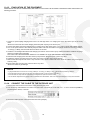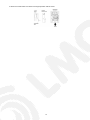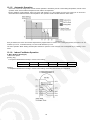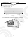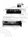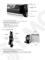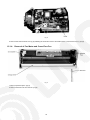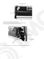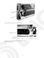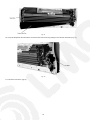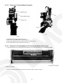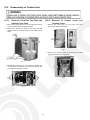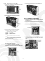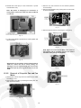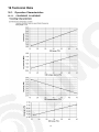
1
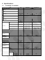
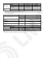
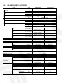
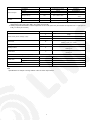
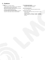
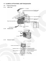
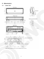
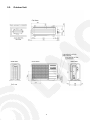
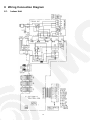
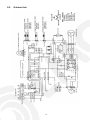
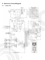
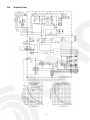
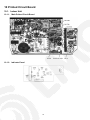
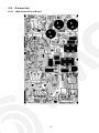
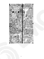
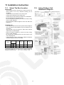
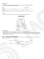
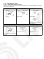
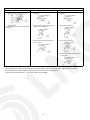
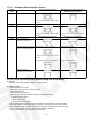
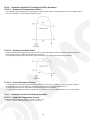
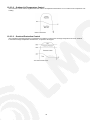
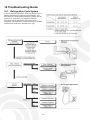
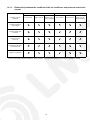
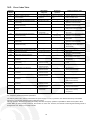
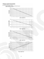
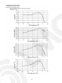
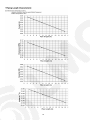
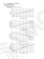
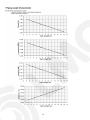
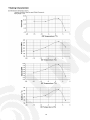
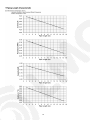
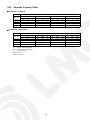
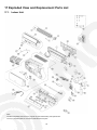
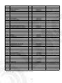
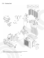
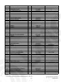
Order No. MAC0706026C2
Air Conditioner
CS-HE9GKE CU-HE9GKE
CS-HE12GKE CU-HE12GKE
TABLE OF CONTENTS
PAGE
1 Safety Precaution ------------------------------------------------ 2
2 Specifications ----------------------------------------------------- 4
2.1. CS-HE9GKE CU-HE9GKE----------------------------- 4
2.2. CS-HE12GKE CU-HE12GKE ------------------------- 6
3 Features ------------------------------------------------------------- 8
4 Location of Controls and Components ------------------- 9
4.1. Product Overview------------------------------------------ 9
5 Dimensions--------------------------------------------------------10
5.1. Indoor Unit--------------------------------------------------10
5.2. Outdoor Unit ----------------------------------------------- 11
6 Refrigeration Cycle Diagram --------------------------------12
7 Block Diagram----------------------------------------------------13
8 Wiring Connection Diagram --------------------------------14
8.1. Indoor Unit--------------------------------------------------14
8.2. Outdoor Unit -----------------------------------------------15
9 Electronic Circuit Diagram -----------------------------------16
9.1. Indoor Unit--------------------------------------------------16
10
11
12
13
14
PAGE
9.2. Outdoor Unit----------------------------------------------- 17
Printed Circuit Board ------------------------------------------ 18
10.1. Indoor Unit ------------------------------------------------- 18
10.2. Outdoor Unit----------------------------------------------- 19
Installation Instruction ---------------------------------------- 21
11.1. Select The Best Location ------------------------------ 21
11.2. Indoor/Outdoor Unit Installation Diagram ---------- 21
11.3. Indoor Unit ------------------------------------------------- 22
11.4. Outdoor Unit----------------------------------------------- 25
Operation and Control ---------------------------------------- 28
12.1. Basic Function -------------------------------------------- 28
12.2. Protection Control---------------------------------------- 36
Servicing Mode -------------------------------------------------- 40
13.1. Auto OFF/ON Button ------------------------------------ 40
13.2. Select Remote Control Transmission Code ------- 40
13.3. Remote Control Button --------------------------------- 41
Troubleshooting Guide --------------------------------------- 42
© 2007 Panasonic HA Air-Conditioning (M) Sdn. Bhd.
(11969-T). All rights reserved. Unauthorized copying
and distribution is a violation of law.
16 Technical Data --------------------------------------------------16.1. Operation Characteristics ----------------------------16.2. Sensible Capacity Chart ------------------------------17 Exploded View and Replacement Parts List----------17.1. Indoor Unit------------------------------------------------17.2. Outdoor Unit ----------------------------------------------
14.1. Refrigeration Cycle System --------------------------- 42
14.2. Breakdown Self Diagnosis Function ---------------- 44
14.3. Error Codes Table---------------------------------------- 45
15 Disassembly and Assembly Instructions --------------- 46
15.1. Disassembly of Indoor Unit ---------------------------- 46
15.2. Disassembly of Outdoor Unit-------------------------- 54
57
57
65
66
66
68
1 Safety Precaution
• Read the following “SAFETY PRECAUTIONS” carefully before perform any servicing.
• Electrical work must be installed or serviced by a licensed electrician. Be sure to use the correct rating of the power plug and
main circuit for the model installed.
• The caution items stated here must be followed because these important contents are related to safety. The meaning of each
indication used is as below. Incorrect installation or servicing due to ignoring of the instruction will cause harm or damage, and
the seriousness is classified by the following indications.
This indication shows the possibility of causing death or serious injury.
This indication shows the possibility of causing injury or damage to properties.
• The items to be followed are classified by the symbols:
This symbol denotes item that is PROHIBITTED from doing.
• Carry out test running to confirm that no abnormality occurs after the servicing. Then, explain to user the operation, care and
maintenance as stated in instructions. Please remind the customer to keep the operating instructions for future reference.
1. Engage dealer or specialist for installation and servicing. If installation or servicing done by the user is defective, it will cause water
leakage, electrical shock or fire.
2. Install according to this installation instruction strictly. If installation is defective, it will cause water leakage, electrical shock or fire.
3. Use the attached accessories parts and specified parts for installation and servicing. Otherwise, it will cause the set to fall, water leakage,
fire or electrical shock.
4. Install at a strong and firm location which is able to withstand the set's weight. If the strength is not enough or installation is not properly
done, the set will drop and cause injury.
5. For electrical work, follow the local national wiring standard, regulation and the installation instruction. An independent circuit and single
outlet must be used. If electrical circuit capacity is not enough or defect found in electrical work, it will cause electrical shock or fire.
6. Use the specified cable and connect tightly for indoor/outdoor connection. Connect tightly and clamp the cable so that no external force will
be acted on the terminal. If connection or fixing is not perfect, it will cause heat-up or fire at the connection.
7. Wire routing must be properly arranged so that control board cover is fixed properly. If control board cover is not fixed perfectly, it will cause
heat-up at connection point of terminal, fire or electrical shock.
8. When connecting the piping, do not allow air or any substances other than the specified refrigerant to enter the refrigeration
cycle. Otherwise, this may lower the capacity, cause abnormally high pressure in the refrigeration cycle, and possibly result in
explosion and injury.
9. Thickness of copper pipes used must be more than 0.8 mm. Never use copper pipes thinner than 0.8 mm.
10. It is desirable that the amount of residual oil is less than 40 mg/10 m.
11. Do not modify the length of the power supply cord or use of the extension cord, and do not share the single outlet with other
electrical appliances. Otherwise, it will cause fire or electrical shock.
2
1. The equipment must be earthed. It may cause electrical shock if grounding is not perfect.
2. Do not install the unit at place where leakage of flammable gas may occur. In case gas leaks and accumulates at surrounding of
the unit, it may cause fire.
3. Carry out drainage piping as mentioned in installation instructions. If drainage is not perfect, water may enter the room and damage the
furniture.
4. Pb free solder has a higher melting point than standard solder; typically the melting point is 50 - 70°F (30 - 40°C) higher. Please use a high
temperature soldering iron. In case of the soldering iron with temperature control, please set it to 700 ± 20°F (370 ± 10°C).Pb free solder
will tend to splash when heated too high (about 1100°F/600°C).
1. Selection of the installation location. Select an installation location which is rigid and strong enough to support or hold the unit, and select
a location for easy maintenance.
2. Power supply connection to the conditioner. Connect the power supply cord of the air conditioner to the mains using one of the following
methods.
Power supply point shall be the place where there is ease for access for the power disconnection in case of emergency.
In some countries, permanent connection of this room air conditioner to the power supply is prohibited.
1. Power supply connection to the receptacle using a power plug. Use an approved power plug with earth pin for the connection to the
socket.
2. Power supply connection to a circuit breaker for the permanent connection. Use an approved circuit breaker for the permanent
connection. It must be a double pole switch with a minimum 3.5 mm contact gap.
3. Do not release refrigerant during piping work for installation, servicing, reinstallation and during repairing a refrigeration parts. Take care of
the liquid refrigerant, it may cause frostbite.
4. Installation work. It may need two people to carry out the installation work.
5. Do not install this appliance in a laundry room or other location where water may drip from the ceiling, etc.
3
2 Specifications
2.1.
CS-HE9GKE CU-HE9GKE
ITEM
UNIT
INDOOR UNIT
OUTDOOR UNIT
Performance Test Condition
EUROVENT
C
Capacity
O
O
L EER
I
N
G Noise Level
H
Capacity
E
A
T COP
I
N
Noise Level
G
Moisture Removal
kW
2.60 (0.60 ~ 3.00)
kCal/h
2240 (520 ~ 2580)
W/W
5.10 (5.00 ~ 4.29)
kCal/hW
4.39 (4.33 ~ 3.69)
dB-A (H/L/Q-Lo)
39 / 26 / 23
46
Power level dB
52
59
kW
3.60 (0.60 ~ 6.50)
kCal/h
3100 (520 ~ 5590)
W/W
5.22 (5.22 ~ 3.78)
kCal/hW
4.49 (4.52 ~ 3.25)
dB-A (H/L/Q-Lo)
42 / 27 / 24
Power level dB
53
1.6
pt/h
3.4
m3/min (ft3/min)
Lo
m3/min (ft3/min)
Me
m3/min (ft3/min)
Hi
m3/min (ft3/min)
Air Volume
Refrigeration Control Device
cm3
Refrigerant (R410A)
Height
Dimension
Cooling; 5.4 (190)
—
Heating; 5.8 (205)
Cooling; 6.1 (215)
—
Heating; 6.5 (230)
Cooling; 8.3 (293)
—
Heating; 9.5 (335)
Cooling; 10.5 (370)
Cooling; 23.8 (840)
Heating; 12.5 (440)
Heating; 23.1 (820)
—
Check Valve & Capillary Tube
—
RB68A or Freol Alpha68M (400)
g (oz)
—
1330 (46.9)
mm (inch)
298 (11-23/32)
540 (21-1/4)
Width
mm (inch)
870 (34-1/4)
780 (30-23/32)
Depth
mm (inch)
199 (7-27/32)
289 (11-3/8)
kg (lbs)
12 (26)
Gas
mm (inch)
Liquid
Net Weight
Pipe Diameter
60
l/h
Q-Lo
Refrigeration Oil
47
37 (82)
9.52 (3/8)
mm (inch)
6.35 (1/4)
Standard Length
m (ft)
7.5 (24.6)
Pipe Length Range
m (ft)
3 (9.8) ~ 15 (49.2)
Height Difference
m (ft)
5 (16.4)
g/m (oz/ft)
20 (0.2)
m (ft)
7.5 (24.6)
Additional Gas Amount
Refrigeration Charge Less
Drain Hose
Compressor
Inner Diameter
mm
16
Length
mm
650
—
Type
—
Hermetic Motor
Motor Type
—
Brushless (6-pole)
Rated Output
W
Type
Material
Motor Type
Fan
—
—
750
Cross-Flow Fan
Propeller Fan
ASG30K1
PP
Transistor (8-pole)
Induction (6-pole)
Input Power
W
25
65
Output Power
W
30
40
Q-Lo (Cool/Heat)
rpm
590 / 690
—
Lo (Cool/Heat)
rpm
660 / 750
—
Fan Speed
Me (Cool/Heat)
rpm
880 / 990
770 / -
Hi (Cool/Heat)
rpm
1100 / 1230
—
4
ITEM
UNIT
INDOOR UNIT
Fin Material
Aluminium
Slit Fin
Corrugated Fin
2 x (15/18/17) x 19.5
2 x 23 x 17
Fin Type
Heat Exchanger
Row x Stage x FPI
Size (W x H x L)
Air Filter
mm
OUTDOOR UNIT
Aluminium (Pre Coat)
36.4 x 504 x 824.2
671 x 322.6 x 30.9
Material
Type
793.7
PP
—
One-Touch
—
1. Cooling capacities are based on indoor temperature of 27°C D.B. (80.6°F D.B.), 19.0°C W.B. (66.2°F W.B.) and outdoor air
temperature of 35°C D.B. (95°F D.B.), 24°C W.B. (75.2°F W.B.)
2. Heating capacities are based on indoor temperature of 20°C D.B. (68°F D.B.) and outdoor air temperature of 7°C D.B. (44.6°F
D.B.), 6°C W.B. (42.8°F W.B.)
Item
Power Source (Phase, Voltage, Cycle)
Unit
ø
Single
V
230
Hz
Input Power
W
Starting Current
A
Running Current
A
Power Factor
%
50
Cooling; 510 (120 ~ 700)
Heating; 690 (115 ~ 1.72k)
3.2
Cooling; 2.4
Heating; 3.2
Cooling; 92
Heating; 94
Power factor means total figure of compressor, indoor fan motor and outdoor fan motor.
*Maximum over current protection
Power Cord
A
Number of core
Length
8.0
3 (1.0mm)
m
1.6
Thermostat
Electronic Control
Protection Device
Electronic Control
Note
• Specifications are subject to change without notice for further improvement.
5
2.2.
CS-HE12GKE CU-HE12GKE
ITEM
UNIT
INDOOR UNIT
OUTDOOR UNIT
Performance Test Condition
EUROVENT
C Capacity
O
O
L EER
I
N
Noise Level
G
kW
3.50 (0.60 ~ 4.00)
kCal/h
3010 (520 ~ 3440)
W/W
4.12 (5.00 ~ 3.81)
kCal/hW
H Capacity
E
A
T COP
I
N
Noise Level
G
42 / 29 / 26
Power level dB
55
61
kW
4.80 (0.60 ~ 7.70)
kCal/h
4130 (520 ~ 6620)
W/W
4.62 (5.22 ~ 3.38)
kCal/hW
3.97 (4.52 ~ 2.90)
dB-A (H/L/Q-Lo)
44 / 33 / 30
Power level dB
55
High 50
63
2.0
pt/h
4.2
Q-Lo
m3/min (ft3/min)
Lo
m3/min (ft3/min)
Me
m3/min (ft3/min)
Hi
m3/min (ft3/min)
Air Volume
Refrigeration Control Device
Cooling; 6.2 (219)
—
Heating; 6.9 (244)
Cooling; 7.0 (247)
—
Heating; 8.0 (282)
Cooling; 8.7 (307)
—
Heating; 10.8 (381)
Cooling; 11.3 (400)
Cooling; 23.8 (840)
Heating; 13.5 (480)
Heating; 23.8 (840)
—
Check Valve & Capillary Tube
cm3
—
RB68A or Freol Alpha68M (400)
g (oz)
—
1330 (46.9)
Height
mm (inch)
298 (11-23/32)
540 (21-1/4)
Width
mm (inch)
870 (34-1/4)
780 (30-23/32)
Depth
mm (inch)
199 (7-27/32)
289 (11-3/8)
kg (lbs)
12 (26)
37 (82)
Refrigeration Oil
Refrigerant (R410A)
Net Weight
Pipe Diameter
High 48
l/h
Moisture Removal
Dimension
3.54 (4.33 ~ 3.28)
dB-A (H/L/Q-Lo)
Gas
mm (inch)
12.7 (1/2)
Liquid
mm (inch)
6.35 (1/4)
Standard Length
m (ft)
7.5 (24.6)
Pipe Length Range
m (ft)
3 (9.8) ~ 15 (49.2)
Height Difference
Additional Gas Amount
Refrigeration Charge Less
Drain Hose
m (ft)
5 (16.4)
g/m (oz/ft)
20 (0.2)
m (ft)
7.5 (24.6)
Inner Diameter
mm
16
Length
mm
650
—
—
Hermetic Motor
Type
Compressor
Motor Type
Rated Output
W
Type
Material
Motor Type
Input Power
Fan
W
Output Power
Fan Speed
—
—
Brushless (6-pole)
—
1.10k
Cross-Flow Fan
Propeller Fan
ASG30K1
PP
Transistor (8-pole)
Induction (6-pole)
25
70
W
30
40
Q-Lo (Cool/Heat)
rpm
670 / 780
—
Lo (Cool/Heat)
rpm
740 / 870
—
Me (Cool/Heat)
rpm
920 / 1090
790 / -
Hi (Cool/Heat)
rpm
1180 / 1310
—
6
ITEM
UNIT
INDOOR UNIT
Fin Material
Aluminium
Slit Fin
Corrugated Fin
3 x (15/18/17) x 19.5
2 x 23 x 17
Fin Type
Heat Exchanger
Row x Stage x FPI
Size (W x H x L)
Air Filter
mm
OUTDOOR UNIT
Aluminium (Pre Coat)
36.4 x 504 x 824.2
671 x 322.6 x 30.9
Material
Type
793.7
PP
—
One-Touch
—
1. Cooling capacities are based on indoor temperature of 27°C D.B. (80.6°F D.B.), 19.0°C W.B. (66.2°F W.B.) and outdoor air
temperature of 35°C D.B. (95°F D.B.), 24°C W.B. (75.2°F W.B.)
2. Heating capacities are based on indoor temperature of 20°C D.B. (68°F D.B.) and outdoor air temperature of 7°C D.B. (44.6°F
D.B.), 6°C W.B. (42.8°F W.B.)
Item
Power Source (Phase, Voltage, Cycle)
Unit
ø
Single
V
230
Hz
50
Input Power
W
Starting Current
A
Running Current
A
Power Factor
%
Cooling; 850 (120 ~ 1.05k)
Heating; 1.04k (115 ~ 2.28k)
4.8
Cooling; 4.0
Heating; 4.8
Cooling; 92
Heating; 94
Power factor means total figure of compressor, indoor fan motor and outdoor fan motor.
*Maximum over current protection
Power Cord
A
Number of core
Length
10.6
3 (1.5mm)
m
1.6
Thermostat
Electronic Control
Protection Device
Electronic Control
Note
• Specifications are subject to change without notice for further improvement.
7
3 Features
• Serviceability Improvement
- Removable and washable Front Panel
- Breakdown Self Diagnosis function
• Product
- Four modes of operation selection
- Powerful mode to reach the desired room temperature
quickly with full power and a strong airflow
- Quiet mode to provide a quiet environment by reducing
the indoor unit operating airflow sound
- 24-hour ON Timer and OFF Timer setting
- Air swing manual and automatic adjusted by Remote
Control for vertical airflow and the horizontal airflow
• Environmental Protection
- Non-ozone depletion substances refrigerant (R410A)
• Operation Improvement
- Random auto restart control after power failure for safety
restart operation
- Advanced inverter technology provides outstanding
energy efficiency and powerful, flexible, comfortable
operation
8
4 Location of Controls and Components
4.1.
Product Overview
4.1.1.
Indoor Unit
4.1.2.
Outdoor Unit
4.1.3.
Remote Control
9
5 Dimensions
5.1.
Indoor Unit
10
5.2.
Outdoor Unit
11
6 Refrigeration Cycle Diagram
12
7 Block Diagram
13
8 Wiring Connection Diagram
8.1.
Indoor Unit
14
8.2.
Outdoor Unit
15
9 Electronic Circuit Diagram
9.1.
Indoor Unit
16
9.2.
Outdoor Unit
17
10 Printed Circuit Board
10.1. Indoor Unit
10.1.1. Main Printed Circuit Board
10.1.2. Indicator Panel
18
10.2. Outdoor Unit
10.2.1. Main Printed Circuit Board
19
20
11 Installation Instruction
11.1. Select The Best Location
11.2. Indoor/Outdoor Unit
Installation Diagram
INDOOR UNIT
• There should not be any heat source or steam near the unit.
• There should not be any obstacles blocking the air
circulation.
• A place where air circulation in the room is good.
• A place where drainage can be easily done.
• A place where noise prevention is taken into consideration.
• Do not install the unit near the door way.
• Ensure the spaces indicated by arrows from the wall, ceiling,
fence or other obstacles.
• Recommended installation height for indoor unit shall be at
least 2.5 m.
OUTDOOR UNIT
• If an awning is built over the unit to prevent direct sunlight or
rain, be careful that heat radiation from the condenser is not
obstructed.
• There should not be any animal or plant which could be
affected by hot air discharged.
• Keep the spaces indicated by arrows from wall, ceiling,
fence or other obstacles.
• Do not place any obstacles which may cause a short circuit
of the discharged air.
• If piping length is over the rated length, additional refrigerant
should be added as shown in the table.
Model
Rated
Max
Max.
Additional
Length Elevation Piping Refrigerant
(m)
(m)
Length
(g/m)
Gas Liquid
(m)
Piping size
HE9GKE
3/8”
1/4”
7.5
5
15
20
HE12GKE
1/2”
1/4”
7.5
5
15
20
Example: For HE9GKE
If the unit is installed at 10 m distance, the quantity of additional
refrigerant should be 50g ...... (10 - 7.5) m x 20 g/m = 50 g
21
11.3. Indoor Unit
11.3.1.
HOW TO FIX INSTALLATION PLATE
11.3.2.
The mounting wall is strong and solid enough to prevent it from
the vibration.
TO DRILL A HOLE IN THE WALL
AND INSTALL A SLEEVE OF
PIPING
1. Insert the piping sleeve to the hole.
2. Fix the bushing to the sleeve.
3. Cut the sleeve until it extrudes about 15 mm from the
wall.
Caution
When the wall is hollow, please be sure to use the
sleeve for tube ass’y to prevent dangers caused by
mice biting the connecting cable.
4. Finish by sealing the sleeve with putty or caulking
compound at the final stage.
: For left side piping, piping connection for liquid should be from
this line.
: For left side piping, piping connection for gas should be about
60 mm from this line.
: For left side piping, piping connection cable should be about
750 mm from this line.
1. Mount the installation plate on the wall with 5 screws or
more.
(If mounting the unit on the concrete wall, consider using
anchor bolts.)
• Line according to the arrows marked on the bottom left
and right sides of the installation plate. The meeting point
of the line extension is the centre of the hole.
11.3.3.
2. Drill the piping plate hole with ø70 mm hole-core drill.
• The hole centre of the right pipe is at the crossing of the
lines which extend vertically from the edge of the
installation plate, and, horizontally, from the side arrow
on the installation plate (see figure above.)
• The hole centre of the left pipe is at the crossing of the
lines which extend vertically from the downward arrow on
the installation plate, and, horizontally from the side
arrow on the installation plate (see figure above.)
• Drill the piping hole at either the right or the left and the
hole should be slightly slanted to the outdoor side.
INDOOR UNIT INSTALLATION
1. For the right rear piping
2. For the right and right bottom piping
22
3. For the embedded piping
(This can be used for left rear piping and left bottom piping
also.)
23
11.3.4.
CONNECT THE CABLE TO THE
INDOOR UNIT
1. The inside and outside connecting cable can be
connected without removing the front grille.
2. Connecting cable between indoor unit and outdoor unit
shall be approved polychloroprene sheathed 5 × 1.5 mm2
flexible cord, type designation 245 IEC 57 or heavier
cord.
• Ensure the colour of wires of outdoor unit and the
terminal Nos. are the same to the indoor’s respectively.
• Earth lead wire shall be longer than the other lead wires
as shown in the figure for the electrical safety in case of
the slipping out of the cord from the anchorage.
• Secure the cable onto the control board with the holder
(clamper).
24
11.4. Outdoor Unit
11.4.1.
INSTALL THE OUTDOOR UNIT
• After selecting the best location, start installation according
to Indoor/Outdoor Unit Installation Diagram.
1. Install at least 40 cm above the ground. Do not install the
unit on the floor.
2. Fix the unit on concrete or rigid frame firmly and
horizontally by bolt (ø10 mm).
Install the outdoor unit in a level position and do not block
the holes. Failure to do so may result in water leakage or
accumulation.
3. When installing at roof, please consider strong wind and
earthquake. Please fasten the installation stand firmly
with bolt or nails.
11.4.2.
CONNECTING THE PIPING
Connecting The Piping To Indoor Unit
Please make flare after inserting flare nut (locate at joint portion of tube assembly) onto the copper pipe
(in case of using long piping).
Connect the piping
• Align the center of piping and sufficiently tighten the flare nut with fingers.
• Further tighten the flare nut with torque wrench in specified torque as stated in the table.
Model
Piping size (Torque)
Gas
Liquid
HE9GKE
3/8” [42 N m]
1/4” [18 N m)
HE12GKE
1/2” [55 N m]
1/4” [18 N m)
O
O
O
O
Do not over tighten, over tightening cause gas leakage.
Connecting The Piping To Outdoor Unit
Decide piping length and then cut by using pipe cutter. Remove burrs from cut edge. Make flare after inserting the flare nut
(locate at valve) onto the copper pipe.
Align center of piping to valves and then tighten with torque wrench to the specified torque as stated in the table.
CUTTING AND FLARING THE PIPING
1. Please cut using pipe cutter and then remove the burrs.
2. Remove the burrs by using reamer. If burrs is not removed, gas leakage may be caused.
Turn the piping end down to avoid the metal powder entering the pipe.
3. Please make flare after inserting the flare nut onto the copper pipes.
25
11.4.3.
EVACUATION OF THE EQUIPMENT
WHEN INSTALLING AN AIR CONDITIONER, BE SURE TO EVACUATE THE AIR INSIDE THE INDOOR UNIT AND PIPES in the
following procedure.
1. Connect a quick-coupling charging hose to the Low and High sides of a charging set and to the service port of the 3-way
valve.
• Be sure to connect the end of the charging hose with quick coupling to the service port.
2. Connect the centre hose of the charging set to a vacuum pump with check valve, or to a vacuum pump with suitable adaptor.
3. Turn on the power switch of the vacuum pump and make sure that the needle in the gauge moves from 0 cmHg (0 MPa) to
-76 cmHg (-0,1 MPa), then evacuate the air for about 15 minutes.
4. Close the Low and High side valves of the charging set and turn off the vacuum pump. Make sure that the needle of the gauge
doesn’t move after about 5 minutes.
Note: FOLLOW THIS PROCEDURE CAREFULLY IN ORDER TO AVOID REFRIGERANT GAS LEAKAGE.
5. Disconnect the charging hose from the vacuum pump and from the service port of the 3-way valve.
6. Tighten the service port caps of the 3-way valve at a torque of 18 N m with a torque wrench.
7. Remove the valve caps of both of the 2-way valve and 3-way valve. Position both of the valves to “OPEN” using a hexagonal
wrench (4 mm).
8. Mount valve caps onto the 2-way valve and the 3-way valve.
• Be sure to check for gas leakage.
O
CAUTION
• If gauge needle does not move from 0 cmHg (0 MPa) to -76 cmHg (-0.1 MPa), in step
above take the following measure:
• If the leak stops when the piping connections are tightened further, continue working from step
.
• If the leak does not stop when the connections are retightened, repair the location of leak.
• Do not release refrigerant during piping work for installation and reinstallation. Take care of the liquid refrigerant, it may cause frostbite.
11.4.4.
CONNECT THE CABLE TO THE OUTDOOR UNIT
1. Remove the control board cover from the unit by loosening the screw.
2. The connecting cable between the outdoor and the indoor units shall be a hose with a 5 x 1.5 mm2 245 IEC57(H05RN-F)
polychloroprene sheath, or heavier.
3. Secure the cable onto the control board with the holder (clamper).
26
4. Attach the control board cover back to the original position with the screw.
27
12 Operation and Control
12.1. Basic Function
Inverter control, which equipped with a microcomputer in determining the most suitable operating mode as time passes,
automatically adjusts output power for maximum comfort always. In order to achieve the suitable operating mode, the
microcomputer maintains the set temperature by measuring the temperature of the environment and performing temperature
shifting. The compressor at outdoor unit is operating following the frequency instructed by the microcomputer at indoor unit that
judging the condition according to internal setting temperature and intake air temperature.
12.1.1. Internal Setting Temperature
Once the operation starts, remote control setting temperature will be taken as base value for temperature shifting processes.
These shifting processes are depending on the air conditioner settings and the operation environment. The final shifted value
will be used as internal setting temperature and it is updated continuously whenever the electrical power is supplied to the unit.
12.1.2. Cooling Operation
12.1.2.1. Thermostat control
• Compressor is OFF when Intake Air Temperature - Internal Setting Temperature < -1.5°C.
• Compressor is ON after waiting for 3 minutes, if the Intake Air Temperature - Internal Setting Temperature > Compressor OFF
point.
12.1.3. Soft Dry Operation
12.1.3.1. Thermostat control
• Compressor is OFF when Intake Air Temperature - Internal Setting Temperature < -1.5°C.
• Compressor is ON after waiting for 3 minutes, if the Intake Air Temperature - Internal Setting Temperature > Compressor OFF
point.
12.1.4. Heating Operation
12.1.4.1. Thermostat control
• Compressor is OFF when Intake Air Temperature - Internal Setting Temperature > +2.0°C.
• Compressor is ON after waiting for 3 minutes, if the Intake Air Temperature - Internal Setting Temperature < Compressor OFF
point.
28
12.1.5. Automatic Operation
• This mode can be set using remote control and the operation is decided by remote control setting temperature, remote control
operation mode, indoor intake air temperature and outdoor air temperature.
• During operation mode judgment, indoor fan motor (with speed of Lo-) and outdoor fan motor are running for 30 seconds to
detect the indoor intake and outdoor air temperature. The operation mode is decided based on below chart.
Every 30 minutes, the indoor and outdoor temperature is judged. Based on remote control setting temperature, the value of T1 will
increase up to 10°C, T2 will decrease by 3°C and T3 will decrease up to 8°C.
The Auto Operation Mode shifting will take place whenever operation mode changed from Cooling/Soft Dry to Heating or vice
versa.
12.1.6. Indoor Fan Motor Operation
A. Basic Rotation Speed (rpm)
i. Manual Fan Speed
[Cooling, Dry]
• Fan speed is determined according to remote control setting.
Remote Control
O
O
O
O
O
Tab
Hi
Me+
Me
Me-
Lo
[Heating]
• Fan speed is determined according to remote control setting and outdoor heat exchanger temperature.
29
ii. Auto Fan Speed
[Cooling, Dry]
• According to room temperature and setting temperature, indoor fan speed is determined automatically.
• The indoor fan will operate according to pattern below.
[Heating]
• According to indoor pipe temperature, automatic heating fan speed is determined as follows.
B. Feedback control
• Immediately after the fan motor started, feedback control is performed once every second.
• During fan motor on, if fan motor feedback 2550 rpm or < 50 rpm continue for 10 seconds, then fan motor error counter
increase, fan motor is then stop and restart. If the fan motor counter becomes 7 times, then H19 - fan motor error is detected.
Operation stops and cannot on back.
12.1.7. Outdoor Fan Motor Operation
Outdoor fan motor is operated with one fan speed only. It starts when compressor starts operation and it stops 30 seconds after
compressor stops operation.
30
12.1.8. Airflow Direction Control
12.1.8.1. Horizontal and Vertical Directions
Vertical louver is controlled by remote control: the Vertical Airflow Direction button on the remote controller and by each operation
mode, as shown in the table below.
Cooling Operation Mode
Manual Operation
• Five-level setting is possible with the remote
controller.
Vertical Automatic Operation
Powerful-ON
• The louver swings between the upper limit
and the lower limit.
• After Powerful is turned on, the louver is
fixed at 26° for 5 minutes or until the Neural
Control is stabilized.
• After the Neural Control is stabilized, the
louver is fixed at 12°.
Dry Operation Mode
Manual Operation
Vertical Automatic Operation
• The louver is fixed at 12°.
• Five-level setting is possible with the remote
controller.
31
Power-ON (Automatic Operation)
• The louver is fixed at 12°.
Heating Operation Mode
Manual Operation
• Five-level setting is possible with the remote
controller.
Vertical Automatic Operation
Power-ON
1. When heat exchanger temperature is less
than 32°C.
1. When heat exchanger temperature is less
than 32°C.
2. When heat exchanger temperature is
between 32°C and 56°C.
2. Quick Heating Operation
3. When heat exchanger temperature is
56°C or more.
3. Warm Heating Operation
4. When heat exchanger temperature is
56°C or more.
•
•
•
•
The vertical louver is closed when the unit is turned off with the remote controller. (Stop position)
The vertical louver is fully opened and move to the setting position when the unit is turned on with the remote controller.
The vertical louver remains at open position when the unit is turned off during operation.
The values in the parentheses ( ) are for the models: CS-HE12GKE.
32
12.1.9. Horizontal Airflow Direction Control
Operation
Mode
Horizontal Automatic Operation
Operation for 5 min. after Powerful-ON or
the Neural Control is stabilized.
Cooling
• The louver horizontally swings at a fixed
cycle.
Horizontal Automatic Operation
Operation for 5 min. after Powerful-ON
Dry
• The louver horizontally swings at a fixed
cycle.
• The louver horizontally swings at a fixed
cycle.
Horizontal Automatic Operation
Heating
Operation after Powerful-ON
When heat exchanger
temperature is below 32°C.
When heat exchanger is between When the Neural Control is stabilized.
32°C (, incl.) and 56°C (, excl.)
In Quick Warm Operation
• The louver horizontally swings at a fixed
cycle.
When the Neural Control is not stabilized.
In Warm Heating Operation
When heat exchanger
temperature is 56°C or more.
12.1.10. Quiet operation (Cooling Mode/Cooling area of Dry Mode)
A. Purpose
To provide quiet cooling operation compare to normal operation.
B. Control condition
a. Quiet operation start condition
• When “quiet” button at remote control is pressed.
Quiet LED illuminates.
b. Quiet operation stop condition
1. When one of the following conditions is satisfied, quiet operation stops:
a. Powerful button is pressed.
b. Stop by OFF/ON switch.
c. Timer “off” activates.
d. Quiet button is pressed again.
2. When quiet operation is stopped, operation is shifted to normal operation with previous setting.
3. When fan speed is changed, quiet operation is shifted to quiet operation of the new fan speed.
4. When operation mode is changed, quiet operation is shifted to quiet operation of the new mode.
5. During quiet operation, if timer “on” activates, quiet operation maintains.
6. After off, when on back, quiet operation is not memorised.
33
C. Control contents
1. Auto fan speed is changed from normal setting to quiet setting of respective fan speed.
This is to reduce sound of Hi, Me, Lo for 3dB.
2. Manual fan speed for quiet operation is -1 step from setting fan speed.
12.1.11. Quiet operation (Heating)
A. Purpose
To provide quiet heating operation compare to normal operation.
B. Control condition
a. Quiet operation start condition
• When “quiet” button at remote control is pressed.
Quiet LED illuminates.
b. Quiet operation stop condition
1. When one of the following conditions is satisfied, quiet operation stops:
a. Powerful button is pressed.
b. Stop by OFF/ON switch.
c. Timer “off” activates.
d. Quiet button is pressed again.
2. When quiet operation is stopped, operation is shifted to normal operation with previous setting.
3. When fan speed is changed, quiet operation is shifted to quiet operation of the new fan speed.
4. When operation mode is changed, quiet operation is shifted to quiet operation of the new mode, expected fan only mode.
5. During quiet operation, if timer “on” activates, quiet operation maintains.
6. After off, when on back, quiet operation is not memorised.
C. Control contents
a. Fan speed auto
1. Indoor FM RPM depends on pipe temp sensor of indoor heat exchanger. Auto fan speed is changed from normal setting to
quiet setting of respective fan speed. This is to reduce sound of Hi, Me, Lo for 3dB.
b. Fan speed manual
1. Manual fan speed for quiet operation is -1 step from setting fan speed.
12.1.12. Powerful Operation
When the Powerful Mode is selected, the unit always forced to operate in Powerful Initial Mode for 5 minutes. Thereafter, the
temperature different (intake air temperature — remote control setting temperature) is detected periodically to judge the operation
zone and suitable control.
After powerful operation activated, it could be turned off when:
• Powerful button is pressed again
• Fan speed button is pressed
• Quiet button is pressed
12.1.12.1. Powerful Operation Zone
Operation Zone
Powerful Initial
Powerful Stable
Powerful Unstable
Control
Fan speed
Fan speed
Setting Temperature
Fan speed
Dry Mode
Cooling Mode
Heating Mode
Lo-
SHi
SHi
Adjust to achieve desired temperature quickly
SLo
34
Auto
Auto
12.1.13. ON Timer Control
ON timer can be set using remote control, the unit with timer set will start operate earlier than the setting time. This is to provide a
comfortable environment when reaching the set ON time.
60 minutes before the set time, indoor (at fan speed of Lo-) and outdoor fan motor start operate for 30 seconds to determine the
indoor intake air temperature and outdoor air temperature in order to judge the operation starting time.
From the judgment, the decided operation will start operate earlier than the set time as shown below.
12.1.14. OFF Timer Control
OFF timer can be set using remote control, the unit with timer set will stop operate at set time.
12.1.15. Auto Restart Control
1. When the power supply is cut off during the operation of air conditioner, the compressor will re-operate within three to four
minutes (there are 10 patterns between 2 minutes 58 seconds and 3 minutes 52 seconds to be selected randomly) after
power supply resumes.
2. This type of control is not applicable during ON/OFF Timer setting.
12.1.16. Indication Panel
LED
POWER
TIMER
QUIET
POWERFUL
Color
Green
Orange
Orange
Orange
Light ON
Operation ON
Quiet Setting ON
Quiet Mode ON
Powerful Mode ON
Light OFF
Operation OFF
Quiet Setting OFF
Quiet Mode OFF
Powerful Mode OFF
Note:
• If POWER LED is blinking, the possible operations of the unit are Hot Start, during Deice operation, operation mode judgement,
or ON timer sampling.
• If Timer LED is blinking, there is an abnormality operation occurs.
35
12.2. Protection Control
12.2.1. Protection Control For All Operations
12.2.1.1. Time Delay Safety Control
1. The compressor will not starts for 3 minutes after stop of the operation.
2. This control is not applicable if the power supply is cut off and on again or after 4-way valve deices condition.
12.2.1.2. 30 Seconds Forced Operation
1. Once compressor starts the operation, it will not stop its operation for 30 seconds.
2. However, it can be stopped with the remote control or the Auto Switch on the indoor unit.
12.2.1.3. Total Running Current Control
1. When the outdoor unit total running current (AC) exceeds X value, the frequency instructed for compressor operation will be
decreased.
2. If the running current does not exceed X value for 5 seconds, the frequency instructed will be increased.
3. However, if total outdoor unit running current exceeds Y value, compressor will be stopped immediately for 3 minutes.
Model
HE9GK
HE12GK
Operation Mode
X (A)
Y (A)
X (A)
Y (A)
Cooling/Soft Dry (A)
4.95
16.99
5.76
16.99
Cooling/Soft Dry (B)
4.43
16.99
5.24
16.99
Cooling/Soft Dry (C)
4.95
16.99
5.76
16.99
Heating
6.2
16.99
8.1
16.99
4. The first 30 minutes of cooling operation, (A) will be applied.
12.2.1.4. IPM (Power transistor) Prevention Control
A. Overheating Prevention Control
1. When the IPM temperature rises to 100°C, compressor operation will stop immediately.
2. Compressor operation restarts after 3 minutes the temperature decreases to 95°C.
B. DC Peak Current Control
1. When electric current to IPM exceeds set value of 20.2 A, the compressor will stop operate. Then, operation will restart
after 3 minutes.
2. If the set value is exceeded again more than 30 seconds after the compressor starts, the operation will restart after 1
minute.
3. If the set value exceeded again within 30 seconds after the compressor starts, the operation will restart after 2 minutes. If
this condition repeats continuously for 7 times, all indoor and outdoor relays will be cut off.
36
12.2.1.5. Compressor Overheating Prevention Control
Instructed frequency for compressor operation will be regulated by compressor discharge temperature. The changes of frequency
are as below figure.
If compressor discharge temperature exceeds 110°C, compressor will stop, occurs 4 times per 20 minutes, timer LED will be
blinking. (“F97” is to be confirmed.)
12.2.1.6. Low Pressure Prevention Control (Gas Leakage Detection)
a. Control start conditions
• For 5 minutes, the compressor continuously operates and outdoor total current is between 0.6A and 1.15A.
• During Cooling and Soft Dry operations:
Indoor suction temperature - indoor piping temperature is below 4°C.
• During Heating operations :
Indoor piping temperature - indoor suction is under 5°C.
b. Control contents
• Compressor stops (and restart after 3 minutes).
• If the conditions above happen 2 times within 20 minutes, the unit will:
- Stop operation
- Timer LED blinks and “F91” indicated.
12.2.1.7. Low Frequency Protection Control 1
When the compressor operates at frequency lower than 25 Hz continued for 240 minutes, the operation frequency will be changed
to 24 Hz for 2 minutes.
12.2.1.8. Low Frequency Protection Control 2
When all the below conditions comply, the compressor frequency will change to lower frequency.
Temperature, T, for:
Cooling/Soft Dry
Heating
Indoor intake air (°C)
T < 14 or T
30
T < 14 or T
28
Outdoor air (°C)
T < 13 or T
38
T < 4 or T
24
Indoor heat exchanger (°C)
T < 30
37
T
0
12.2.2. Protection Control For Cooling & Soft Dry Operation
12.2.2.1. Outdoor Air Temperature Control
• The compressor operating frequency is regulated in accordance to the outdoor air temperature as shown in the diagram below.
• This control will begin 1 minute after the compressor starts.
12.2.2.2. Cooling Overload Control
• Detects the Outdoor pipe temperature and carry out below restriction/limitation (Limit the compressor Operation frequency)
• The compressor stops if outdoor pipe temperature exceeds 63°C
• If the compressor stops 4 times in 20 minutes, Timer LED blinking (F95: outdoor high pressure rise protection)
12.2.2.3. Freeze Prevention Control
1.
2.
3.
4.
When indoor heat exchanger temperature is lower than 0°C continuously for 6 minutes, compressor will stop operating.
Compressor will resume its operation 3 minutes after the indoor heat exchanger is higher than 13°C.
At the same time, indoor fan speed will be higher than during its normal operation.
If indoor heat exchanger temperature is higher than 13°C for 5 minutes, the fan speed will return to its normal operation.
12.2.3. Protection Control For Heating Operation
12.2.3.1. Intake Air Temperature Control
Compressor will operate at Max frequency if below condition occur:
1. When the indoor intake air temperature is 30°C or above.
38
12.2.3.2. Outdoor Air Temperature Control
• The maximum current value is regulated when the outdoor air temperature rises above 14°C in order to avoid compressor overloading.
12.2.3.3. Overload Protection Control
• The compressor operating frequency is regulated in accordance to indoor heat exchanger temperature as shown in below.
• If the heat exchanger temperature exceeds 60°C, compressor will stopped.
39
13 Servicing Mode
13.1. Auto OFF/ON Button
1. AUTO OPERATION MODE
The Auto operation will be activated immediately once the Auto OFF/ON button is pressed. This operation can be used to
operate air conditioner with limited function if remote control is misplaced or malfunction.
2. TEST RUN OPERATION (FOR PUMP DOWN/SERVICING PURPOSE)
The Test Run operation will be activated if the Auto OFF/ON button is pressed continuously for more than 5 seconds. A “beep”
sound will occur at the fifth seconds, in order to identify the starting of Test Run operation (Forced cooling operation). Within 5
minutes after Forced cooling operation start, the Auto OFF/ON button is pressed for more than 5 seconds. A 2 “beep” sounds
will occur at the fifth seconds, in order to identify the starting of Forced heating operation.
The Auto OFF/ON button may be used together with remote control to set / change the advance setting of air conditioner
operation.
3. REMOTE CONTROL NUMBER SWITCH MODE
The Remote Control Number Switch Mode will be activated if the Auto OFF/ON button is pressed continuously for more than
11 seconds (3 “beep” sounds will occur at 11th seconds to identify the Remote Control Number Switch Mode is in standby
condition) and press any button at remote control to transmit and store the desired transmission code to the EEPROM.
For transmission code selection explanation, please refer to “Select Remote Control Transmission Code”.
4. REMOTE CONTROL RECEIVING SOUND OFF/ON MODE
The Remote Control Receiving Sound OFF/ON Mode will be activated if the Auto OFF/ON button is pressed continuously for
more than 16 seconds (4 “beep” sounds will occur at 16th seconds to identify the Remote Control Receiving Sound Off/On
Mode is in standby condition) and press “AC Reset” button and then press “Check” button at remote control.
Press “Auto OFF/ON button” to toggle remote control receiving sound.
- Short “beep”: Turn OFF remote control receiving sound.
- Long “beep”: Turn ON remote control receiving sound.
After Auto OFF/ON Button is pressed, the 20 seconds counter for Remote Control Receiving Sound OFF/ON Mode is
restarted.
13.2. Select Remote Control Transmission Code
• There are 4 types of remote control transmission code could be selected and stored in EEPROM of indoor unit. The indoor unit
will only operate when received signal with same transmission code from remote control. This could prevent signal interference
when there are 2 or more indoor units installed nearby together.
• To change remote control transmission code, short or open jumpers at the remote control printed circuit board.
40
Remote Control Printed Circuit Board
Jumper A (J-A)
Jumper B (J-B)
Remote Control No.
Short
Open
A (Default)
Open
Open
B
Short
Short
C
Open
Short
D
13.3. Remote Control Button
13.3.1. SET BUTTON
• To check current remote control transmission code
- Press for more than 10 seconds.
• To change the air quality sensor sensitivity
- Press and release with pointer.
- Press the Timer Decrement button to select sensitivity:
1. Low Sensitivity
2. Standard (Default)
3. Hi Sensitivity
- Confirm setting by pressing Timer Set button, a “Beep” sound will be heard. LCD returns to original display after 2 seconds.
- LCD returns to original display if remote control does not operate for 30 seconds.
13.3.2. CLOCK BUTTON
• To change the remote control’s time format
- Press for more than 5 seconds.
13.3.3. RESET (RC)
• To clear and restore the remote control setting to factory default
- Press once to clear the memory.
13.3.4. RESET (AC)
• To restore the unit’s setting to factory default
- Press once to restore the unit’s setting.
13.3.5. TIMER
• To change indoor unit indicator’s LED intensity
- Press continuously for 5 seconds.
13.3.6. TIMER
• To change remote control display from Degree Celsius to Degree Fahrenheit.
- Press continuously for 10 seconds.
41
14 Troubleshooting Guide
14.1. Refrigeration Cycle System
In order to diagnose malfunctions, make sure that there are no
electrical problems before inspecting the refrigeration cycle.
Such problems include insufficient insulation, problem with the
power source, malfunction of a compressor and a fan.
The normal outlet air temperature and pressure of the
refrigeration cycle depends on various conditions, the standard
values for them are shown in the table on the right.
42
14.1.1. Relationship between the condition of the air conditioner and pressure and electric
current
Cooling Mode
Condition of the air
conditioner
Low Pressure
High Pressure
Heating Mode
Electric current
during operating
Low Pressure
High Pressure
Electric current
during operating
Insufficient refrigerant
(gas leakage)
Clogged capillary tube
or Strainer
Short circuit in the
indoor unit
Heat radiation deficiency
of the outdoor unit
Inefficient compression
• Carry out the measurements of pressure, electric current, and temperature fifteen minutes after an operation is started.
43
14.2. Breakdown Self Diagnosis Function
14.2.1. Self Diagnosis Function (Three Digits Alphanumeric Code)
7. The breakdown diagnosis mode will be canceled unless
pressing the CHECK button continuously for 5 seconds or
operating the unit for 30 seconds.
8. The same diagnosis can be repeated by turning power on
again.
• Once abnormality has occurred during operation, the unit
will stop its operation, and Timer LED blinks.
• Although Timer LED goes off when power supply is turned
off, if the unit is operated under a breakdown condition, the
LED will light up again.
• In operation after breakdown repair, the Timer LED will no
more blink. The last error code (abnormality) will be stored in
IC memory.
• To make a diagnosis
1. Timer LED start to blink and the unit automatically stops
the operation.
2. Press the CHECK button on the remote controller
contiguously for 5 seconds.
3. “- -” will be displayed on the remote controller display.
Note: Display only for “- -”. (No transmitting signal, no
receiving sound and no Power LED blinking.)
4. Press the “TIMER”
or
button on the remote
controller. The code “H00” (no abnormality) will be
displayed and signal will be transmitted to the main unit.
5. Every press of the button (up or down) will increase
abnormality numbers and transmit abnormality code
signal to the main unit.
6. When the latest abnormality code on the main unit and
code transmitted from the remote controller are matched,
power LED will light up for 30 seconds and a beep sound
(continuously for 4 seconds) will be heard. If no codes are
matched, power LED will light up for 0.5 seconds and no
sound will be heard.
7. The breakdown diagnosis mode will be canceled unless
pressing the CHECK button continuously for 5 seconds or
operating the unit for 30 seconds.
8. The LED will be off if the unit is turned off or the RESET
button on the main unit is pressed.
• To clear memorized error (Protective operation) status
after repair:
1. Turn power on.
2. Press the AUTO button for 5 seconds (A beep receiving
sound) on the main unit to operate the unit at Forced
Cooling Operation modes.
3. Press the CHECK button on the remote controller for
about 1 second with a pointed object to transmit signal to
main unit. A beep sound is heard from main unit and the
data is cleared.
• Temporary Operation (Depending on breakdown status)
1. Press the AUTO button (A beep receiving sound) on the
main unit to operate the unit. (Remote control will become
possible.)
2. The unit can temporarily be used until repaired.
• To display memorized error (Protective operation)
status
1. Turn power on.
2. Press the CHECK button on the remote controller
contiguously for 5 seconds.
3. “- -” will be displayed on the remote controller display.
Note: Display only for “- -”. (No transmitting signal, no
receiving sound and no Power LED blinking.)
4. Press the “TIMER”
or
button on the remote
controller. The code “H00” (no abnormality) will be
displayed and signal will be transmitted to the main unit.
The power LED lights up. If no abnormality is stored in the
memory, three beeps sound will be heard.
5. Every press of the button (up or down) will increase
abnormality numbers and transmit abnormality code
signal to the main unit.
6. When the latest abnormality code on the main unit and
code transmitted from the remote controller are matched,
power LED will light up for 30 seconds and a beep sound
(continuously for 4 seconds) will be heard. If no codes are
matched, power LED will light up for 0.5 seconds and no
sound will be heard.
44
Error Code
Operation
Temporary items
H23
Cooling
H27, H28
Cooling, Heating
Emergency Operation
with limited power
14.3. Error Codes Table
Diagnosis
display
Abnormality / Protection control
H00
No abnormality detected
H11
Indoor / outdoor abnormal
communication
Abnormality
Judgement
—
Emergency
operation
Primary location to verify
Normal operation
> 1 min after starting
operation
Indoor fan operation
only
• Internal / external cable connections
• Indoor / Outdoor PCB
H12
Connection capability rank abnormal
—
—
H14
Indoor intake air temperature sensor
abnormality
Continue for 5 sec.
—
• Intake air temperature sensor
(detective or disconnected)
—
H15
Outdoor compressor temperature
sensor abnormality
Continue for 5 sec.
—
• Compressor temperature sensor
(detective or disconnected)
H16
Outdoor Current Transformer open
circuit
—
—
• Outdoor PCB
• IPM (Power transistor) module
H19
Indoor fan motor merchanism lock
7 times occurance
continuously.
—
• Indoor PCB
• Fan motor
H23
Indoor heat exchanger temperature
sensor abnormality
Continue for 5 sec.
O
(Cooling only)
H25
E-Ion breakdown
—
—
• Indoor PCB
• E-Ion PCB
H27
Outdoor air temperature sensor
abnormality
Continue for 5 sec.
O
• Outdoor temperature sensor
(defective or disconnected)
H28
Outdoor heat exchanger temperature
sensor abnormality
Continue for 5 sec.
O
• Outdoor heat exchanger
temperature sensor (defective or
disconnected)
• Indoor/Outdoor supply voltage
• Heat exchanger temperature sensor
(defective or disconnected)
H33
Indoor/Outdoor wrong connection
—
—
H38
Indoor/outdoor mismatch (brand code)
—
—
H58
Abnormal gas sensor
Continue for 6 hours
—
• Gas sensor
(defective or disconnected)
H98
Indoor high pressure protection
—
—
• Air filter dirty
• Air circulation short circuit
H99
Indoor heat exchanger anti-freezing
protection
—
—
• Insufficient refrigerant
• Air filter dirty
F11
Cooling / Heating cycle changeover
abnormality
4 times occurance
within 30 minutes
—
• 4-way valve
• V-coil
F90
PFC control
4 times occurance
within 20 minutes
—
• Voltage at PFC
F91
Refrigeration cycle abnormal
2 times occurance
within 20 minutes
—
• No refrigerant
(3-way valve is closed)
F93
Outdoor compressor abnormal
revolution
4 times occurance
within 20 minutes
—
• Outdoor compressor
F95
Cool high pressure protection
4 times occurance
within 20 minutes
—
• Outdoor refrigerant circuit
F96
IPM (power transistor) overheating
protection
—
—
• Excess refrigerant
• Improper heat radiation
• IPM (Power transistor)
F97
Outdoor compressor overheating
protection
4 times occurance
within 20 minutes
—
• Insufficient refrigerant
• Compressor
F98
Total running current protection
3 times occurance
within 20 minutes
—
• Excess refrigerant
• Improper heat radiation
F99
Outdoor Direct Current (DC) peak
detection
7 times occurance
continuously
—
• Outdoor PCB
• IPM (Power transistor)
• Compressor
—
Note:
“O” - Frequency measured and fan speed fixed.
The memory data of error code is erased when the power supply is cut off, or press the Auto Switch until “beep” sound heard
following by pressing the “CHECK” button at Remote Control.
Although operation forced to stop when abnormality detected, emergency operation is possible for certain errors (refer to Error
Codes Table) by using Remote Control or Auto Switch at indoor unit. However, the Remote Control signal receiving sound is
changed from one “beep” to four “beep” sounds.
45
15 Disassembly and Assembly Instructions
High voltages are generated in the electrical parts area by the capacitor. Ensure that the capacitor has discharged sufficiently before proceeding
with repair work. Failure to heed this caution may result in electric shocks.
15.1. Disassembly of Indoor Unit
15.1.1. Removal of the Front Grille
Fig. 1
1. Lift to open the horizontal vane gently. Remove the 2 caps and 2 screws at the bottom of discharge vane. (Fig.1)
Fig. 2
2. Remove the front panel by pressing Lever Arm with finger. (Fig.2)
46
Fig. 3
3. Remove the Top Panel by pressing the triangle marks. (Fig.3)
4. Remove the screw (one) in center part of the unit. (Fig.3)
5. Remove the Front Grille by releasing the 4 hooks at the top of the Front Grille. Hold both side of the Front Grille and remove it
by pulling up and toward you gently. (Fig.3)
15.1.2. Removal of Control Board Complete
Fig. 4
47
Fig. 5
1. Remove the Control board cover. (Fig.4)
2. Remove the screw at the control board then pull out the control board. (Fig.5)
3. Release CN-TH from evaporator. (Fig.5)
4. Release earth wire screw from the evaporator. (Fig.5)
5. Disconnect below connectors from PCB. (Fig.5)
• Terminal FG GRN.
• CN-STM1 - Air Swing Motor for vertical louver.
• CN-STM2 - Air Swing Motor for horizontal louver.
• CN-FM - Indoor Unit Fan Motor.
15.1.3. Removal of PCB
Fig. 7
Fig. 6
1.
2.
3.
4.
5.
Disconnect lead wire from terminal board complete. (Fig.6)
Disconnect live wire (brown) from terminal plate connector. (Fig.6)
Release screw from the control board. (Fig.6)
Remove control board cover (L) and control board cover (R) from the control board. (Fig.6)
Remove control board cover (R) from control board cover (L) by releasing the hooks. (Fig.7)
48
Fig. 8
6. Remove the control boards cover (L) by releasing the hooks then remove the PCB from the control board cover (L). (Fig.8)
15.1.4. Removal of Fan Motor and Cross-Flow Fan
Fig. 9
1. Remove particular piece. (Fig.9)
2. Remove the drain hose from the unit. (Fig.9)
49
Fig. 10
3. Remove connector at the Gear Complete. (Fig.10)
4. Release screw at Gear Complete then remove the Gear Complete. (Fig.10)
5. Pull the Discharge Grille downward then removed it. (Fig.9)
Fig. 11
6. Remove the Fan Motor Cover by removing four screws from the Fan Motor Cover. (Fig.11)
50
Fig. 12
7. Remove the screw on the left side of evaporator. (Fig.12)
Fig. 13
8. Loosen the screw between the Cross-Flow Fan and Fan Motor. (Fig.13)
9. Remove the bearing. (Fig.12)
51
Fig. 14
10. Lift up the Evaporator and remove the Cross-Flow Fan from the unit by pulling it to the left and downward. (Fig. 14)
Fig. 15
11. Pull out the Fan Motor. (Fig.15)
52
15.1.5. Removal of Terminal Board Complete
Fig. 17
Fig. 16
1.
2.
3.
4.
Detach the Power supply cord screw. (Fig.17)
Remove screw at Terminal Board Complete. (Fig.17)
Remove two particular pieces, the Terminal Board Complete. (Fig.16)
Removed live (brown) and neutral (blue) wire. (Fig.17)
15.1.6. Removal of Air Swing Motors for Vertical and Horizontal Louvers.
1. The Air Swing Motors for Vertical and Horizontal louvers can be removed without removal of Discharge Grille.
2. Remove the screws from the motors and then remove the cable connectors. (Fig.18)
53
15.2. Disassembly of Outdoor Unit
15.2.1. Removal of Cabinet Top Plate and
Cabinet Front Plate
15.2.2. Removal of Control Cover and
Terminal Cover
1. Remove the screws (three: two on the right side and one
on the left side) and the Cabinet Top Plate.
2. Remove the screws (six: three on the upper side and
another three on the lower side) on the Cabinet Front
Plate.
1. Remove the screw (one) on the Control Cover and
remove it by sliding it downward.
Fig. 3
2. Remove the Terminal Cover by removing the screws
(two) and releasing the hooks (two).
Fig. 1
3. Release the hooks (four: two on the right and another two
on the left) of the Cabinet Front Plate and remove the
Front Plate by holding it up a little.
Fig. 4
Fig. 2
54
15.2.3. Removal of Control Box
5. Remove the Control Box from the unit by holding it up.
1. Remove the Control Board by releasing the hooks (four:
two each on the right and left).
Fig. 5
2. Remove the screw (one) fixing the Control Box.
Fig. 8
15.2.4. Removal of Control Board
1. Remove the Cabinet Top Plate and Cabinet Front Plate
according to 15.2.1.
2. Remove the Control Cover and Terminal Cover according
to 15.2.2.
3. Remove the Control Box according to 15.2.3.
4. Disconnect the Control Terminals (Four cables).
Fig. 6
3. Remove a variety of connectors and Terminals.
• Compressor cables (red, blue and yellow)
...... Remove the Connector (white).
• CN-HOT ...... 4-way Valve
• CN-FM1 ...... Outdoor Fan Motor
• CN-STM ...... Expansion Valve
• CN-TH
...... Sensor Complete (Outdoor Air/Pipe Temp.)
• CN-DIS
...... Sensor Complete (Discharge Air Temperature)
• Reactor Connectors (two)
Fig. 9
5. Place the Control Box reversely and remove the screws
(two) on the both sides of the Control Box B (for Terminal
Plate).
4. Remove the interconnect cables and the Earth Wire (one
screw).
• Interconnect cables (red, white and black)
......... Disconnect them from the Terminals.
• The earth terminal (yellow-green)
......... Remove it by unscrewing. (one screw)
• Remove the screws (two) fixing the Terminal part and the
Cabinet Side Plate.
Fig. 10
Fig. 7
55
6. Release the hooks (four) on the Control Box A (Lower
Control PCB Cover).
3. Remove only the Connector for the CN-FM1 (Outdoor
unit Fan Motor).
4. Remove the Propeller Fan by turning the nut in the center
of the fan clockwise.
Note: Be careful of hanging-up of connectors or
wiring cables such as the earth wire when the Box A
is removed.
Fig. 14
5. Remove the Fan Motor by loosening the screw (four).
Fig. 11
7. For the Control Board, replacement is made together with
the Control Box.
Fig. 15
Note: Adjust the location of the Boss in the center of
the Propeller and the matching groove on the shaft of
the Motor when putting them together.
Fig. 12
• Replacement of the Outdoor Control PCB should be
made as a whole unit due to silicon pasting, etc.
although it can be separated PCB part from Control
BOX plastic part by removing the screws (six) on the
PCB.
Fig. 16
15.2.5. Removal of Propeller Fan and Fan
Motor
1. Remove the Cabinet Top Plate and Cabinet Front Plate
according to 15.2.1.
2. Remove the Control Box by releasing the hooks (four: two
each on the both sides).
Fig. 17
Fig. 13
56
16 Technical Data
16.1. Operation Characteristics
16.1.1. CS-HE9GKE CU-HE9GKE
57
58
59
60
16.1.2. CS-HE12GKE CU-HE12GKE
61
62
63
64
16.2. Sensible Capacity Chart
O CS-HE9GKE CU-HE9GKE
230V
Outdoor Temp. (°C)
30
35
40
46
Indoor wet
bulb temp.
TC
SHC
IP
TC
SHC
IP
TC
SHC
IP
TC
SHC
IP
17.0°C
2.58
1.96
0.47
2.41
1.88
0.50
2.24
1.80
0.54
2.04
1.71
0.58
19.0°C
2.60
0.51
19.5°C
2.83
2.05
0.48
2.65
1.97
0.51
2.46
1.89
0.55
2.24
1.80
0.59
22.0°C
3.09
2.12
0.48
2.88
2.04
0.52
2.68
1.97
0.56
2.44
1.88
0.60
O CS-HE12GKE CU-HE12GKE
230V
Outdoor Temp. (°C)
30
35
40
46
Indoor wet
bulb temp.
TC
SHC
IP
TC
SHC
IP
TC
SHC
IP
TC
SHC
IP
17.0°C
3.47
2.63
0.78
3.24
2.52
0.84
3.02
2.43
0.90
2.74
2.30
0.97
19.5°C
3.81
2.76
0.79
3.56
2.65
0.85
3.31
2.55
0.91
3.01
2.43
0.98
22.0°C
4.15
2.86
0.81
3.88
2.75
0.87
3.61
2.65
0.93
3.28
2.53
1.00
19.0°C
3.50
0.85
TC - Total Cooling Capacity (kW)
SHC - Sensible Heat Capacity (kW)
IP
- Input Power (kW)
Indoor 27°C/19°C
Outdoor 35°C/24°C
65
17 Exploded View and Replacement Parts List
17.1. Indoor Unit
Note
The above exploded view is for the purpose of parts disassembly and replacement.
The non-numbered parts are not kept as standard service parts.
66
REF. NO.
QTY.
CS-HE9GKE
CS-HE12GKE
1
CHASSY COMPLETE
PART NAME & DESCRIPTION
1
CWD50C1551
←
2
FAN MOTOR, DC 30W 3PH
1
CWA981194CB
←
←
3
CROSS-FLOW FAN CO.
1
CWH02C1024
4
BEARING ASSY
1
CWH64K1005
←
5
HOLDER-FAN MOTOR
1
CWD911313
←
6
SCREW-HOLDER FAN MOTOR
4
XTT4+12CFJ
←
7
L SHAPED PLATE-FOR CHASSY
1
CWD601065B
←
8
EVAPORATOR CO.
1
CWB30C2285
CWB30C2286
9
FLARE NUT (1/4)
1
CWT25086
←
10
HOLDER SENSOR
1
CWH321076
←
←
11
BACK COVER CHASSIS
1
CWD911316B
12
DISCHARGE GRILLE COMPLETE
1
CWE20C2739
←
13
VERTICAL VANE
16
CWE241239
←
14
CONNECTING BAR
1
CWE261056A
←
15
CONNECTING BAR
1
CWE261057A
←
16
GEAR COMPLETE (VERTICAL VANE)
1
CWH68C1017
←
17
A.S. MOTOR, DC SINGLE 12V 300 OHM
1
CWA981107J
←
18
LEAD WIRE FOR AIR SWING MOTOR
1
CWA67C4688
←
←
19
FULCRUM
1
CWH621031A
20
HORIZONTAL VANE COMPLETE
1
CWE24C1212
←
21
A.S. MOTOR, DC SINGLE 12V 250 OHM
1
CWA981105J
←
22
LEADWIRE (A.S. MOTOR AND GEAR)
1
CWA67C5748
←
←
23
WIRE NET
1
CWD041083
24
CAP-DRAIN TRAY
1
CWH521091
←
25
FLARE NUT (3/8) (1/2)
1
CWT251031
CWT251032
26
SENSOR COMPLETE
1
CWA50C2467
←
27
HOLDER SENSOR
1
CWH32137
←
28
GEAR-COMPLETE (INTAKE GRILLE)
1
CWH68C1021
←
29
PIPE COVER
1
CWD911317
←
30
ELECTRONIC CONTROLLER-MAIN
1
CWA73C2872
←
31
CONTROL BOARD COVER ( L )
1
CWH131163
←
32
CONTROL BOARD COVER ( R )
1
CWH13K1010
←
33
TERMINAL BOARD CO (WITH RELAY)
1
CWA28C2192J
←
34
P.S. CORD
1
CWA20C2599
CWA20C2600
35
CONTROL BOARD COVER (F)
1
CWH131165
←
36
ELECTRONIC CON (RCVR-INDICATOR)
1
CWA744944
←
37
INDICATOR HOLDER
1
CWD932309
←
38
FRONT GRILLE COMPLETE
1
CWE11C3881
←
←
39
GRILLE DOOR COMPLETE
1
CWE14C1017
40
INTAKE GRILLE COMPLETE
1
CWE22C1397
←
41
SCREW-FRONT GRILLE
3
XTT4+16CFJ
←
42
CAP-FRONT GRILLE
2
CWH521088
←
43
AIR FILTER
2
CWD001163
←
44
FLEXIBLE PIPE
1
CWH851110
←
45
FRAME FOR AIR FILTER
1
CWD661108
←
46
SUPER ALLERU BUSTER FILTER
1
CWD001135
←
47
REMOTE CONTROL COMPLETE
1
CWA75C3115
←
48
INSTALLATION HOLDER
1
CWH36C1019
←
49
BAG COMPLETE - INSTALLATION SCREW
1
CWH82C1496
←
(NOTE)
• All parts are supplied from PHAAM, Malaysia (Vendor Code: 061).
67
17.2. Outdoor Unit
Note
The above exploded view is for the purpose of parts disassembly and replacement.
The non-numbered parts are not kept as standard service parts.
68
REF. NO.
QTY.
CU-HE9GKE
1
CHASSY ASS'Y
PART NAME & DESCRIPTION
1
CWD50K2171
CU-HE12GKE
←
2
ANTI-VIBRATION BUSHING
3
CWH50077
←
3
COMPRESSOR, DC 220V
1
5CS110XBD04
←
4
NUT-COMPRESSOR MOUNT
3
CWH56000J
←
5
CRANKCASE HEATER
1
CWA341026
←
6
SOUND PROOF MATERIAL
1
CWG302464
←
7
BRACKET FAN MOTOR
1
CWD541089
←
8
FAN MOTOR, DC 40W 3PH
1
ARW44X8P40AC
←
9
SCREW-BRACKET FAN MOTOR
2
CWH551217
←
10
SCREW-FAN MOTOR MOUNT
4
CWH55252J
←
11
PROPELLER FAN ASSY
1
CWH03K1014
←
12
NUT-PROPELLER FAN
1
CWH56053J
←
13
CONDENSER COMPLETE
1
CWB32C2165
←
14
4-WAYS VALVE
1
CWB001037J
←
CWB011523
15
3-WAYS VALVE (GAS)
1
CWB011434
16
STRAINER
1
CWB111004
←
17
RECEIVER
1
CWB14011
←
18
HOLDER-SENSOR
1
CWH321009
←
19
HOLDER-SENSOR
1
CWH32075
←
20
HOLDER-COUPLING
1
CWH351025
←
21
2-WAYS VALVE
1
CWB021400
←
22
ACCUMLATOR
1
CWB131044
←
23
TUBE ASSY (EXP. VALVE STRAINER)
1
CWT01C4251
←
24
STRAINER
1
CWB11094
←
25
DRYER
1
CWB101016J
←
26
SENSOR-COMPLETE
1
CWA50C2066
←
27
TERMINAL COVER
1
CWH171039A
←
28
NUT-TERMINAL COVER
1
CWH7080300J
←
29
WIRE NET
1
CWD041111A
←
30
SOUND-PROOF BOARD
1
CWH151176
←
31
REACTOR
1
G0C193J00003
G0C193J00004
32
HOLDER-SENSOR
1
CWH321023
←
33
SENSOR-COMPLETE
1
CWA50C2402
←
34
SENSOR-COMPLETE
1
CWA50C2281
←
35
CONTROL BOARD CASING
1
CWH102294
←
36
TERMINAL BOARD ASS'Y
1
CWA28K1021J
←
37
ELECTRONIC CONTROLLER-MAIN
1
CWA73C2824R
CWA73C2825R
38
CONTROL BOARD COVER
1
CWH131264
←
39
OVER HEAT PROTECTOR COMPLETE
1
CWA14C1012
←
40
V-COIL CO. FOR 4-WAY VALVE
1
CWA43C2144J
←
41
V-COIL COMPLETE FOR EXP. VALVE
1
CWA43C2058J
←
42
HOLDER-SENSOR
2
CWH32143
←
43
CABINET SIDE PLATE (L)
1
CWE041278A
←
44
CABINET SIDE PLATE (R)
1
CWE041280A
←
45
CABINET FRONT PLATE-COMPLETE
1
CWE06C1136
←
46
CABINET TOP PLATE
1
CWE031014A
←
47
FLARE NUT (1/4)
1
CWT251030
←
48
FLARE NUT (3/8) (1/2)
1
CWT251031
CWT251032
49
CONTROL BOARD COVER
1
CWH131213
←
50
CONTROL BOARD COVER-COMPLETE
1
CWH13C1145
←
51
OPERATING INSTRUCTION
1
CWF565733
←
52
INSTALLATION INSTRUCTION
1
CWF613288
←
53
INSTALLATION INSTRUCTION
1
CWF613289
←
(NOTE)
• All parts are supplied from PHAAM, Malaysia (Vendor Code: 061).
69
[PHAAM] Printed in Malaysia
SFBZ0708-01