1
Model A-576 A-PAD
Preamplifier, Amplifier, Discriminator
with Bias Supply
Operating and Service Manual
Printed in U.S.A.
ORTEC Part No. 761930
Manual Revision D
0202
$GYDQFHG 0HDVXUHPHQW 7HFKQRORJ\ ,QF
a/k/a/ ORTEC®, a subsidiary of AMETEK®, Inc.
WARRANTY
ORTEC* warrants that the items will be delivered free from defects in material or workmanship. ORTEC makes no
other warranties, express or implied, and specifically NO WARRANTY OF MERCHANTABILITY OR FITNESS FOR
A PARTICULAR PURPOSE.
ORTEC’s exclusive liability is limited to repairing or replacing at ORTEC’s option, items found by ORTEC to be
defective in workmanship or materials within one year from the date of delivery. ORTEC’s liability on any claim of
any kind, including negligence, loss, or damages arising out of, connected with, or from the performance or breach
thereof, or from the manufacture, sale, delivery, resale, repair, or use of any item or services covered by this
agreement or purchase order, shall in no case exceed the price allocable to the item or service furnished or any part
thereof that gives rise to the claim. In the event ORTEC fails to manufacture or deliver items called for in this
agreement or purchase order, ORTEC’s exclusive liability and buyer’s exclusive remedy shall be release of the buyer
from the obligation to pay the purchase price. In no event shall ORTEC be liable for special or consequential
damages.
Quality Control
Before being approved for shipment, each ORTEC instrument must pass a stringent set of quality control
tests designed to expose any flaws in materials or workmanship. Permanent records of these tests are
maintained for use in warranty repair and as a source of statistical information for design improvements.
Repair Service
If it becomes necessary to return this instrument for repair, it is essential that Customer Services be contacted in
advance of its return so that a Return Authorization Number can be assigned to the unit. Also, ORTEC must be
informed, either in writing, by telephone [(865) 482-4411] or by facsimile transmission [(865) 483-2133], of the nature
of the fault of the instrument being returned and of the model, serial, and revision ("Rev" on rear panel) numbers.
Failure to do so may cause unnecessary delays in getting the unit repaired. The ORTEC standard procedure requires
that instruments returned for repair pass the same quality control tests that are used for new-production instruments.
Instruments that are returned should be packed so that they will withstand normal transit handling and must be
shipped PREPAID via Air Parcel Post or United Parcel Service to the designated ORTEC repair center. The address
label and the package should include the Return Authorization Number assigned. Instruments being returned that
are damaged in transit due to inadequate packing will be repaired at the sender's expense, and it will be the sender's
responsibility to make claim with the shipper. Instruments not in warranty should follow the same procedure and
ORTEC will provide a quotation.
Damage in Transit
Shipments should be examined immediately upon receipt for evidence of external or concealed damage. The carrier
making delivery should be notified immediately of any such damage, since the carrier is normally liable for damage
in shipment. Packing materials, waybills, and other such documentation should be preserved in order to establish
claims. After such notification to the carrier, please notify ORTEC of the circumstances so that assistance can be
provided in making damage claims and in providing replacement equipment, if necessary.
Copyright © 2002, Advanced Measurement Technology, Inc. All rights reserved.
*ORTEC® is a registered trademark of Advanced Measurement Technology, Inc. All other trademarks used
herein are the property of their respective owners.
iii
CONTENTS
WARRANTY . . . . . . . . . . . . . . . . . . . . . . . . . . . . . . . . . . . . . . . . . . . . . . . . . . . . . . . . . . . . . . . . . . . . . . . . . . . ii
PHOTOGRAPH . . . . . . . . . . . . . . . . . . . . . . . . . . . . . . . . . . . . . . . . . . . . . . . . . . . . . . . . . . . . . . . . . . . . . . . . iv
1. DESCRIPTION . . . . . . . . . . . . . . . . . . . . . . . . . . . . . . . . . . . . . . . . . . . . . . . . . . . . . . . . . . . . . . . . . . . . . .
1
2. SPECIFICATIONS . . . . . . . . . . . . . . . . . . . . . . . . . . . . . . . . . . . . . . . . . . . . . . . . . . . . . . . . . . . . . . . . . .
2.1. PERFORMANCE . . . . . . . . . . . . . . . . . . . . . . . . . . . . . . . . . . . . . . . . . . . . . . . . . . . . . . . . . . . . . . .
2.2. CONTROLS . . . . . . . . . . . . . . . . . . . . . . . . . . . . . . . . . . . . . . . . . . . . . . . . . . . . . . . . . . . . . . . . . . .
2.3. INPUT . . . . . . . . . . . . . . . . . . . . . . . . . . . . . . . . . . . . . . . . . . . . . . . . . . . . . . . . . . . . . . . . . . . . . . .
2.4. OUTPUTS . . . . . . . . . . . . . . . . . . . . . . . . . . . . . . . . . . . . . . . . . . . . . . . . . . . . . . . . . . . . . . . . . . . . .
2.5. ELECTRICAL AND MECHANICAL . . . . . . . . . . . . . . . . . . . . . . . . . . . . . . . . . . . . . . . . . . . . . . . . . .
2
2
2
2
2
3
3. INSTALLATION . . . . . . . . . . . . . . . . . . . . . . . . . . . . . . . . . . . . . . . . . . . . . . . . . . . . . . . . . . . . . . . . . . . . .
3.1. JUMPER SETTINGS . . . . . . . . . . . . . . . . . . . . . . . . . . . . . . . . . . . . . . . . . . . . . . . . . . . . . . . . . . . . .
3.2. CONNECTION TO DETECTOR . . . . . . . . . . . . . . . . . . . . . . . . . . . . . . . . . . . . . . . . . . . . . . . . . . . .
3.3. CONNECTION TO POWER . . . . . . . . . . . . . . . . . . . . . . . . . . . . . . . . . . . . . . . . . . . . . . . . . . . . . . .
3.4. OUTPUT CONNECTIONS . . . . . . . . . . . . . . . . . . . . . . . . . . . . . . . . . . . . . . . . . . . . . . . . . . . . . . . .
3.5. ENERGY OUTPUT FULL-SCALE ADJUSTMENT . . . . . . . . . . . . . . . . . . . . . . . . . . . . . . . . . . . . . .
3
3
4
4
4
4
4. OPERATION . . . . . . . . . . . . . . . . . . . . . . . . . . . . . . . . . . . . . . . . . . . . . . . . . . . . . . . . . . . . . . . . . . . . . . .
4.1. GENERAL . . . . . . . . . . . . . . . . . . . . . . . . . . . . . . . . . . . . . . . . . . . . . . . . . . . . . . . . . . . . . . . . . . . . .
4.2. CONNECTING A DETECTOR . . . . . . . . . . . . . . . . . . . . . . . . . . . . . . . . . . . . . . . . . . . . . . . . . . . . .
5
5
5
5. THEORY OF OPERATION . . . . . . . . . . . . . . . . . . . . . . . . . . . . . . . . . . . . . . . . . . . . . . . . . . . . . . . . . . . .
6
LIST OF FIGURES
Fig. 1.
Fig. 2.
Fig. 3.
Fig. 4.
Fig. 5.
Block diagram of Alpha Spectrometer. . . . . . . . . . . . . . . . . . . . . . . . . . . . . . . . . . . . . . . . . . . . . . . . . .
Jumper Locations for Setting Polarity on the PWB. . . . . . . . . . . . . . . . . . . . . . . . . . . . . . . . . . . . . . . .
Side-Panel Test Pulser Selection. . . . . . . . . . . . . . . . . . . . . . . . . . . . . . . . . . . . . . . . . . . . . . . . . . . . .
Typical A-PAD Output Waveforms with 5-MeV Test Pulser. . . . . . . . . . . . . . . . . . . . . . . . . . . . . . . . .
Detailed Block Diagram of the Model A-576 A-PAD. . . . . . . . . . . . . . . . . . . . . . . . . . . . . . . . . . . . . . .
1
3
4
5
7
iv
1
ORTEC MODEL A-576 A-PAD
Preamplifier, Amplifier, Discriminator with Bias Supply
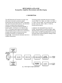
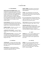
1. DESCRIPTION
The ORTEC Model A-576 A-PAD is a single- wide
NIM module intended for performing alpha
spectroscopy and counting when used in conjunction
with a silicon surface barrier detector. The instrument
includes a variable detector bias supply, a
preamplifier, a shaping and stretching amplifier, a
biased amplifier, a test pulser, and a discriminator
(Fig. 1). The detector bias supply and the amplifier
have selectable polarity so that it can be ued with any
charged-particle silicon semiconductor detector.
Examples are ORTEC's conventional and
Ruggedized- Si surface barrier detectors and its ionimplanted Si detectors.
The energy ranges controllable from the front panel
are 3 to 8 MeV, 4 to 7 MeV, 3 to 5 MeV, 4 to 6 MeV, 5
to 7 MeV, and 6 to 8 MeV. The internal test pulser can
provide a signal at 5 MeV, 6 MeV, or 7 MeV by
internal jumper selection.
In addition to the calibrated Energy output, the
COUNT front-panel BNC connector provides a NIMstandard positive logic pulse for gross alpha counting
and/or routing. The DET BIAS MONITOR front-panel
test points permit monitoring detector leakage current
and detector bias voltage.
Fig. 1. Block diagram of Alpha Spectrometer.
2
2. SPECIFICATIONS
2.1. PERFORMANCE
DETECTOR AND ELECTRONIC NOISE <25 keV
FWHM when used with ORTEC R Series, 300 mm2
and 450 mm2 charged-particle detectors, and <35 keV
for 600 mm2 and 900 mm2 R Series charged-particle
detectors when connection of the Model A-576 to the
detector is made with <2 ft of RG-62A/U cable.
System noise is dependent on detector capacitance
plus cable capacitance and leakage current. Electronic
noise is typically 5 keV with a slope of 25 eV/pF silicon
equivalent (based on = 3.6 eV and t = 0.5 µs
(internal amplifier).
PULSE SHAPING Internal 0.5-µs active filter semiGaussian pulse shaping amplifier provides a pulse that
is stretched prior to being output through the Bias
Amplifier to give a 4-µs-wide positive output pulse.
ENERGY RANGES 3 TO 8 MeV, 4 to 7 MeV, 3 to 5
MeV, 4 to 6 MeV, 5 to 7 MeV, 6 to 8 MeV.
ENERGY RANGE Six positions on the front-panel
switch for selecting the desired energy range (see
PERFORMANCE).
E BIAS 15-turn potentiometer on the front panel
permits screwdriver adjustment of the energy output
bias point to be varied by ±10% for ease of setup with
the data acquisition system.
E
15-turn potentiometer on the front panel permits
screwdriver adjustment of the maximum energy output
range to be varied from 7.75 to 10.25 V for ease of
setup with the data acquisition system.
TEST PULSER PWB jumper (J2) allows selection of
internal pulser energies of 5 MeV, 6 MeV, or 7 MeV.
INPUT/BIAS POLARITY PWB jumpers allow
selection of either positive or negative detector voltage
polarity. Negative for ORTEC Surface Barrier or IonImplanted Ruggedized detectors, or positive for
conventional detectors. (Shipped in Negative position.)
CALIBRATED TEST PULSER Equivalent Energy
5 MeV, 6 MeV, or 7 MeV. (Shipped at 5 MeV). Rate is
100 Hz.
2.3. INPUT
DETECTOR BIAS VOLTAGE Continuously variable
over range of 0 to 100 V. Polarity selectable with
printed wiring board (PWB) jumper shipped in negative
position (appropriate for ORTEC R Series detectors).
Shipped set to 100 V.
PREAMP IN Front- and rear-panel BNCs accept an
input signal from semiconductor charged-particle
detectors. Either RG-62A/U or RG-71A/U cable is
recommended to minimize excess capacitance and
hence noise.
2.2. CONTROLS
2.4. OUTPUTS
TEST/BIAS/OFF Front-panel, three-position toggle
switch controls both the detector bias voltage and the
test pulser. Front-panel LED is illuminated when the
bias voltage is on.
ENERGY Front- and rear-panel BNC connectors
provides a positive stretched pulse from 7.75 to
10.25 V maximum, depending on the setting of the E
gain control corresponding to an energy range
selected on the front-panel switch. Pulse width =
4 µs; Z0 = 100 6; dc-coupled.
DET BIAS ADJ Front-panel potentiometer for
controlling the bias voltage applied to the detector.
Continuously variable from 0 to ±100 V.
3
COUNT Front-panel BNC connector provides a NIMstandard positive pulse for gross alpha counting or
routing. Pulse width 3.5 µs for any event with energy
>2.5 MeV. Z0 = 50 6; dc-coupled.
DET BIAS MONITOR Voltage can be monitored
between front-panel test point (labeled HV) and
ground. Detector current can be monitored across
resistor between front-panel test points DET and HV.
The current is 1 µA per volt when using a voltmeter
with 10-M6 input impedance.
2.5. ELECTRICAL AND MECHANICAL
POWER REQUIRED +12 V, 90 mA; -12 V, 45 mA;
+24 V, 100 mA; -24 V, 45 mA.
WEIGHT
Net 0.9 kg (2.0 lb).
Shipping 2.25 kg (5.0 lb).
DIMENSIONS NIM-standard single-width module
3.43 × 22.13 cm (1.35 × 8.714 in.) per TID-20893
(Rev).
3. INSTALLATION
3.1. JUMPER SETTINGS
Six plug-in jumpers on the printed circuit board (PWB)
must be set for compatible operation. These jumpers
are accessible when the side panel is removed from
the instrument chassis. Five of the jumpers are used
to select either positive or negative detector voltage
polarity and the corresponding correct amplifier
polarity. Negative bias is required for ORTEC
Ruggedized detectors; positive for conventional
surface-barrier or ion-implanted detectors. These five
internal jumpers need to be changed only when a
Ruggedized detector is replaced with one of the other
detectors or vice versa. The sixth jumper is used to
set the pulse generator equivalent energy (see TEST
PULSE).
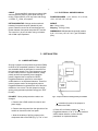
POLARITY When polarity selection needs to be
changed:
a. Remove the A-PAD module from the bin and
power supply.
b. Remove the side panel from the right side of the
module as viewed from the front panel.
c. Note the locations of all five jumpers on the
components side of the PWB (Fig. 2). The "+" and
Fig. 2. Jumper Locations for Setting Polarity on the PWB.
"" orientation for each of the jumpers is
etched on the PWB.
d. Place all five of these jumpers at "" for a
Ruggedized detector, or at "+" for a conventional
surface barrier detector or silicon dioxidepassivated, ion-implanted detector.
4
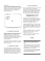
TEST PULSE The sixth jumper is used to set the
equivalent energy of the test pulser to 5, 6, or 7 MeV.
Change this jumper only if an energy other than 5 MeV
is desired from the test pulser. The jumper can be
changed through the hole in the side panel to an
alternate position (Fig. 3).
3.4. OUTPUT CONNECTIONS
When an external BNC cable longer than 10 ft is used
for the output connection, the characteristic
impedance of the cable should match the impedance
of the output used. The ENERGY output should use
93-6 RG-62A/U cable, and the COUNT outputs
should be connected using 50-6 RG-58A/U cable.
3.5. ENERGY OUTPUT FULL-SCALE
ADJUSTMENT (Other than 10 V)
The full-scale output from the ENERGY output is
normally set to 10 V, which matches the input range of
many multichannel analyzers (MCAs). The second
most common input range for MCAs is 8 V. The
procedure for 8-V full scale is as follows:
Fig. 3. Side-Panel Test Pulser Selection.
3.2. CONNECTION TO DETECTOR
A direct connection with 93-6 or 100-6 shielded cable
should be made between the detector and the
PREAMP IN connector on the A-PAD. For best
results, keep the length of this cable as short as
possible (due to the capacitive loading of the cable) to
minimize preamplifier noise and maintain the
preamplifier stability.
Type RG-62/U cable is recommended for the detectorto preamplifier connection. This is 93-6 cable with a
capacity of 13.5 pF/ft.
3.3. CONNECTION TO POWER
The A-PAD is designed for operation in a NIMstandard bin and power supply such as the ORTEC
4001/4002/402 series. The power supply furnishes
operating power requirements at ±12 V and ±24 V.
These NIM bins have test points on the power supply
control panel to monitor the dc-voltage level.
1. Set the TEST/BIAS/OFF switch to TEST. Set the
ENERGY RANGE switch to 3&5 MeV with the TEST
Pulser jumper set to 5 MeV. Note: Any Range can be
used when the TEST Pulser is set to the top of the
Range.
2. Observe the ENERGY output on an oscilloscope
and trigger on the COUNT output. The output
amplitude should be about 10 V.
3. Adjust the front-panel E control for 8-V output.
Continue with operation of the A-576.
NOTICE
Damage may result to the preamplifier or the
detector unless the following precautions are
taken:
The TEST/BIAS/OFF switch must be in the OFF
position before connecting a low impedance or a
cable, capacitor, or other capacitive device to the
PREAMP IN connector on the A-PAD.
Turn the BIAS switch to OFF before making ANY
connections to the PREAMP IN connector and
before disconnecting the detector.
5
4. OPERATION
4.1. GENERAL
The information in Section 3 includes all of the
preliminary selections that are to be made for the APAD. Operation consists of connecting a detector and
proceeding with data collection.
4.2. CONNECTING A DETECTOR
Start with the TEST/BIAS/OFF switch in the OFF
position. Connecting the detector with the bias voltage
ON may damage the FET transistor at the input of the
preamplifier or destroy the detector.
Then proceed as follows:
1. With the bias OFF, connect the detector to the
A-PAD with a short cable (preferably RG-62A/U).
2. Set the TEST/BIAS/OFF switch at TEST and adjust
the front-panel HV control for the desired bias voltage
between 0 and 100 V. The bias voltage can be
monitored on the front-panel test point jacks with a
voltmeter. After turning ON, or adjusting, the bias
voltage, wait for the preamplifier to settle; this takes
about one minute.
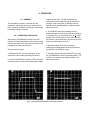
3. The ENERGY output should display positive,
stretched pulses at a 100-Hz rate with an amplitude of
5 V (shown in Fig. 4), if the Range is set to 4&6 MeV
and the TEST pulser jumper is in the 5 MeV position.
The COUNT output should have a positive logic pulse
with a 6-µs width (shown in Fig. 4).
4. System electronic noise can be tested by
measuring the FWHM spread of the pulser peak on
the MCA from the ENERGY output.
5. The test pulser can then be turned OFF by moving
the TEST/BIAS/OFF switch to the BIAS position. The
A-PAD is now ready to count alpha samples or do
alpha spectrometry.
Fig. 4. Typical A-PAD Output Waveforms with 5-MeV Test Pulser.
6
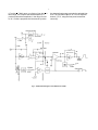
5. THEORY OF OPERATION
The complete schematic for the A-576 A-PAD (No.
752500) is included at the back of this manual.
Fig. 5 is a block diagram of the electronics.
The detector voltage (TEST/BIAS/OFF) switch on the
front panel turns power ON and OFF for the variable
100-V bias power supply. The power is on to the BIAS
supply in both the TEST and BIAS positions.
The polarity is set by Jumper J1, which is actually
three separate jumpers (see schematic). The indicated
polarity is negative, which is appropriate when an
ORTEC Ruggedized detector is used. When the
detector voltage is negative, its output pulses are
positive. When they pass through the inverting chargesensitive preamplifier, they are negative, and this is
the polarity that is then selected by the pair of jumpers
(J3) on the PWB. If a conventional surface barrier, or
ion-implanted, detector is used, all five of these
jumpers must be changed to "+" because these
detectors, positively biased, generate negative output
pulses, which are then inverted, resulting in positive
pulses at the J3 location in the circuit.
The 100-V power supply output on the PWB can be
tested for both polarity and amplitude at test point
TP1, which is identified on the PWB. The variable 0 to
100 V bias voltage can be measured at the front-panel
test point jack labeled HV.
The detector leakage current can be measured across
the 1.1-M6 resistor between front-panel test points HV
and DET, using a 10-M6 impedance meter. The
voltage (in volts) converts to µA of detector current.
The output of the Bias supply is applied through a
high impedance (totaling 11 M6) to the dc connection
between the detector and the preamplifier.
The output from the charge-sensitive preamplifier can
be checked at TP2. The nominal conversion gain is
45 mV/MeV. The preamplifier gain from the External
Pulser input is nominally "1" at TP2.
The pulser switch (TEST/BIAS/OFF) on the front
panel turns power on and off for the test pulser. The
test pulser can be set to furnish the equivalent pulse
amplitude for 5, 6, and 7 MeV to the input to the
preamplifier. A screwdriver calibration, included on the
PWB for factory adjustment of the test pulser circuit,
should not be changed by the customer. When the
front-panel toggle switch is set at BIAS, the test pulser
is turned off and does not appear in the output
spectrum.
Pulses from the detector and/or the test pulser are
inverted by the preamplifier and are furnished as the
input to the amplifier that includes the first integration
and differentiation shaping circuits. The amplifier can
be calibrated by a factory-adjusted trim potentiometer
on the PWB. The output is a shaped negative pulse
that can be observed at test point TP3.
The pulse at TP3 is furnished into a fixed-level
discriminator (U3), and through a diode dc-restorer
and integration network. If the amplitude represents
~2.5 MeV or more, the discriminator fires and
generates a positive-shaped pulse that is used to
enable the stretcher. This pulse is also provided as the
COUNT output signal. The pulse from the second
integration shaping circuit is furnished to the stretcher.
If the stretcher is enabled, the peak amplitude is
stretched to improve the measurement accuracy of the
multichannel analyzer, which uses the ENERGY
output for measurement. If the stretcher is not enabled
(because the pulse represents <2.5 MeV), the output
is passed to the biased amplifier without being
stretched. The output of the stretcher is a negative
pulse that can be monitored at test point TP4 on
the PWB.
The biased amplifier accepts the stretcher output and
the bias level selected by the front-panel ENERGY
RANGE switch (low end of range). The bias level, or
lower level, accepted into the bias amplifier can be set
at 3, 4, 5, or 6 MeV by the ENERGY RANGE switch,
which can be adjusted by ±10% by the front-panel
screwdriver control, E BIAS.
The function of the biased amplifier is to subtract the
bias level from the input pulse amplitude and to
amplify the excess amplitude by a factor of 10 on the
3&5, 4&6, 5&7, and 6&8 MeV ranges, and by a factor
7
6.7 on the 4&7 MeV range, or a factor of 4 on the 3&8
MeV range. The output of the biased amplifier is a
positive pulse with an amplitude, in the range from 0.1
to 10 V, which is proportional to the amount by which
the detected input energy exceeds the selected bias
level. The full-scale output of 10 V can be adjusted
down to 7.75 V, using the front-panel screwdriver
control (E).
Fig. 5. Detailed Block Diagram of the Model A-576 A-PAD.