Download RESEARCH&DEVELOPMENT OF AMERICA, INC.
Transcript
RESEARCH&DEVELOPMENT OF AMERICA, INC.
5420 DANIELS STREET SUITE A, CHINO CA 91710 · (800)634-9166 · (909)628-4722 · FACSIMILE (909)591-2198
www.yoshimura-rd.com
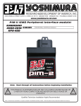
PIM II (EMS Peripheral Interface Module)
SUZUKI
2006-2010
LT-R450
R-433-2115
PERIPHERAL INTERFACE M ODULE
Note: Read through all instructions before beginning installation.
!
THIS PRODUCT IS INTENDED FOR USE ONLY IN CLOSED COURSE RACING OR
OTHER OFF ROAD COMPETITION AND NEVER ON PUBLIC ROADS OR
HIGHWAYS
Installation by Qualified Technician Only
NOTE: IN THE STATE OF CALIFORNIA, IT IS ILLEGAL TO MODIFY THE EMISSION CONTROL SYSTEM. WHICH INCLUDES THE FUEL INJECTION SYSTEM OF ANY VEHICLE.
!
Installation Procedures:
Page 2
Installation Steps:
1 Make sure the ATV is turned off and cooled down before
beginning installation of the PIM II.
2 Remove the seat, left and right side covers, fuel tank
cover, and front fender. Refer to factory service manual.
3 Remove the gas tank bolts, lift up the gas tank and the
protective plastic cover and route the Yoshimura PIM
harness from injector compartment toward stock ECU
securely and away from moving parts (Fig. 1).
Toward
stock ECU
Toward
injector, TP,
and CKP plug
PIM
harness
4 Locate the stock injector, and throttle position (TP) plugs
(Fig. 2). Disconnect them and connect the Yoshimura PIM
harness injector, and TP plugs (Fig. 2).
Fig. 1
5 Locate crankshaft position sensor (CKP) plug (Fig. 3) on
the left side of the subframe. Disconnect it and connect
the Yoshimura PIM harness CKP plugs (Fig. 4).
Injector
plug
6 Remove the bottom headlight bolt (Fig. 5). Tilt the front
of the headlight upwards. Remove the rubber boot at the
back of the headlight. Remove the light bulb assembly by
rotating it.
NOTE: Be careful when working with the removed bulb, it
is easy to damage. Do not touch the glass top of the
bulb.
TP
plug
7 Locate the gray 6 wire connector and the black 4 wire
connector near the stock ECU (Fig. 6) and disconnect
them. Move both sides of the connectors and the light
bulb assembly behind the stock aluminum bracket. Plug
the connectors back together and reinstall the light bulb.
8 Swap the stock plastic clamp that secures all wires from
the front side to the inside of the stock aluminum bracket.
Secure the wires (Fig. 7).
9 Attach supplied Hook-&-Loop Adhesive to Yoshimura PIM
bracket and bottom of the PIM. Loosen the rectifier bolts
and slide rectifier away from the center of the stock
aluminum bracket. Tighten the bolts. Mount the PIM
aluminum bracket onto the stock aluminum bracket and
secure it with the stock bolt. Install the PIM into the
bracket. Connect the black PIM harness plug into the PIM
(Fig. 8).
Fig. 2
CKP
plug
Fig. 3
Installation Procedures:
Page 3
10 Disconnect Cherry Bomb if installed (The PIM2 has
the Cherry Bomb feature integrated into the kit).
Connect PIM2 power supply connector to diagnostic
connector ( Black connector in Fig. 10). The grey
connector will not be disconnected or altered in any
way.
11 Check that all wiring connections are tight.
Stock injector
plug
Stock
TP
plug
PIM
injector
plugs
12 Reinstall headlight, front fender, fuel tank cover, side
panels, ignition switch, and seat. Check that wiring is
not pinched or kinked.
13 If any problem is found, please carefully follow
through the installation steps again. If problem still
persists, please call Yoshimura technical department
at (800)634-9166.
CAUTION: For vehicles equipped with the Yoshimura
Kickstart Kit AND an ignition cut switch, check to
make sure that shutting the vehicle off does not
transmit an excessive voltage spike through the frame
or circuit. Damage to the PIM2 unit may occur if
excessive voltage is transmitted through the unit.
PIM
CKP
plugs
Stock
CKP
plugs
PIM
TP
plugs
Fig. 4
Remove
bolt
Tilt
headlight
upwards
Fig. 5
Fig. 5
Black
plug
Headlight
wires
Diagnostic
Connector
Grey
plug
Fig. 6
Plastic
clamp
Gray
plug
Fig. 7
Installation Procedures:
Page 4
Slide rectifier
this way
Power Supply
Loosen
bolts
Stock
bolt
Fig. 14
Fig. 9
Fig. 8
To Throttle
Position Sonsor
To PIM
To Fuel
Injector
Map Selector
Connector
To Data
Connector
PIM Power
Supply
Parts list:
DESCRIPTION
PIM
PIM Harness
PIM2 Software
USB Cable
Aluminum Bracket
Yoshimura USA sticker
Hook-&-Loop Adhesive
Cable Tie
Instructions
QTY
1
1
1
1
1
1
1
8
1
PART #
R-433B
R-433-2115-HB
R-433-CD
R-433-USB
R-433-2115-BRKT
17029
5000-V
ZT-300
INST KIT
To Crank
Position Sensor
Installation Procedures:
Page 5
Operation Steps:
The PIM comes with two preprogrammed maps. Map 1 is
when the ATV has a Yoshimura full exhaust system with
spark arrester installed and stock air box lid removed.
Map 2 is when the ATV has a Yoshimura full exhaust
system with spark arrester removed, and stock air box lid
removed.
Map 1
is active
Use the map selector plug to switch between maps. Map
1 is active when the selector plug is connected (Fig. 11).
Map 2 is active while the selector plug is disconnected
(Fig. 12).
NOTE: Before connecting the map selector plug remove
the map selector plug cover (Fig. 12).
Fig. 11
Map 2
is active
Map
selector
plug cover
Fig. 12


