1
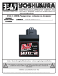
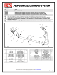
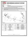
RESEARCH&DEVELOPMENT OF AMERICA, INC.
5420 DANIELS STREET SUITE A, CHINO CA 91710 · (800)634-9166 · (909)628-4722 · FACSIMILE (909)591-2198
www.yoshimura-rd.com
PIM II (EMS Peripheral Interface module)
KAWASAKI
2008-2010
KFX-450
R-433-2415
PERIPHERAL INTERFACE M ODULE
Note: Read through all instructions before beginning installation.
!
THIS PRODUCT IS INTENDED FOR USE ONLY IN CLOSED COURSE RACING OR
OTHER OFF ROAD COMPETITION AND NEVER ON PUBLIC ROADS OR
HIGHWAYS
Qualified Technician Installation Highly Recommended
NOTE: IN THE STATE OF CALIFORNIA, IT IS ILLEGAL TO MODIFY THE EMISSION CONTROL SYSTEM. WHICH INCLUDES THE FUEL INJECTION SYSTEM OF ANY VEHICLE.
!
Installation Procedures:
Page 2
Installation Steps:
1 Make sure the ATV is turned off and cooled down before
beginning installation of the PIM II.
2 Remove the seat, left and right side covers, fuel tank
cover, fuel tank, and front fender. Refer to the factory
service manual.
3 Locate the stock fuel injector (Fig. 1), disconnect the
stock connector and connect the Yoshimura PIM harness
to the stock fuel injector and connector. (Fig. 2)
4 Locate the throttle position sensor connector near the
left side of the subframe. (Fig. 3) Disconnect the stock
TPS connector and connect the Yoshimura PIM harness to
the TPS sensor and connector.
PIM
injector
connectors
Fig. 2
5 Attach PIM harness ground wire to ATV’s chassis ground.
(Fig. 4)
6 Route the PIM harness forward to the front of the ATV.
(Fig. 5)
7 Locate a black wire protector near the front of the ATV.
Inside the black wire protector find the crank position
sensor (CPS) connector, a black two pin connector.
(Fig. 6) Disconnect the CPS sensor and connect the PIM
harness.
TPS
connector
Fig. 3
Injector
connector
Ground
Fig. 1
Fig. 4
Installation Procedures:
Page 3
8 In the black wire protector as in step 7, find the four pin
black connector housing one pink, one light green, one
blue/yellow and one brown wire. (Fig. 8) Disconnect the
connectors cover and connect PIM Power wire connector.
9 Remove the two OEM bolts holding the regulator in
place and install the PIM bracket using the OEM bolts.
(Fig. 8)
10 Attach supplied Hook-&-Loop adhesive to Yoshimura PIM
bracket and bottom of the PIM. Connect the black PIM
harness plug into the PIM (Fig. 10).
CPS
connectors
11 Check that all wiring connections are tight.
Fig. 6
12 Reinstall headlights and bracket, front fender, fuel tank
and cover, side panels, ignition switch, and seat. Check
that wiring is not pinched or kinked.
13 If any problem is found, please carefully follow through
the installation steps again. If problem still persists,
please call Yoshimura technical department at
PIM
CPS
connectors
Fig. 7
Black four
pin plug
PIM
harness
Toward
injector, TP,
and CKP plug
Toward
Front of ATV
PIM harness
power connector
Fig. 5
Fig. 8
Installation Procedures:
Page 4
PIM
box
Bolt
Bolt
PIM
bracket
Fig. 10
Fig. 9
To Crankshaft
Position Senor
To Data Connector
To Fuel Injector
To Power Supply
Map Selector Connector
To Throttle
Position Sensor
To PIM
Parts list:
DESCRIPTION
PIM
PIM Harness
Aluminum Bracket
Yoshimura USA sticker
Hook-&-Loop Adhesive
Cable Tie
PIM2 Software CD
USB Cable
Instructions
Ground
QTY
1
1
1
1
1
8
1
1
1
PART #
R-433B
R-433-2415-HB
R-433-2415-BRKT
17029
5000-V
ZT-300
R-433-CD
R-433-USB
INST KIT
Installation Procedures:
Page 5
Operation Steps:
The PIM comes with two preprogrammed maps. Map 0 is
when the ATV has a Yoshimura full exhaust system with
spark arrester installed and stock air box lid removed.
Map 1 is when the ATV has a Yoshimura full exhaust
system with spark arrester removed, and stock air box lid
removed.
Map 1
is active
Use the map selector plug to switch between maps. Map
0 is active when the selector plug is connected (Fig. 11).
Map 1 is active while the selector plug is disconnected
(Fig. 12).
NOTE: Before connecting the map selector plug remove
the map selector plug cover (Fig. 12).
Fig. 11
Map 2
is active
Map
selector
plug cover
Fig. 12