1
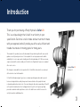
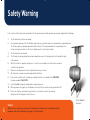
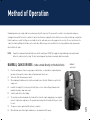
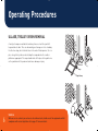
CellarLift
Service & Operation Manual
for Penny Hydraulics Cellar Lifts
www.pennyhydraulics.com
Contents
3
Introduction
4
Safety Warning
5
Operating Procedures
9
Fault Finding
10
Warranty Policy
11
Maintenance
13
Service Requirements
14
Service Contract Form
15
Data, Specification, COSHH & Terminal Disposal
16
Survey, Installation & Commissioning
19
Declaration of Conformity
19
Signs
20
Exploded Views
20
Spare Parts
21
Electric and Hydraulic Schematic Diagrams
22
Training Record
23
Work Record
Sloping CellarLift
with groceries
BinLift
Service
With our service contract you can be sure of continued safe, reliable use of the equipment and full
compliance with current legislation. Go to page 13 for more details.
Vertical CellarLift
with cases
Introduction
Thank you for purchasing a Penny Hydraulics CellarLift.
This is a unique design that is built in our factory to your
specification. Each one is tailor-made and we trust that it meets
with your approval and will provide you with a safe, efficient and
trouble free means of moving goods for many years.
This manual tells you what you need to know about its operation together with some useful
guidance on safety and general care. It also explains the servicing requirements and the
availability of a service agreement should you wish to take advantage of it. We have our own
engineers around the country lead by our Central Service Department to give an exceptional
after-sales service.
We strongly recommend that each operator of the CellarLift be trained in its use and read
all the details set out in this booklet.
Sloping CellarLift
with barrel
CellarLifts, although varying in type, have a common operating procedure and in general
terms are designed to be used by two persons to move drinks or other pub, hotel and
restaurant goods between two levels. Care must always be taken when operating a CellarLift
as they do not normally have inter-locking gates but rely on the safe layout, operating
procedures and inherent design features such as the hold-to-run controls to ensure the
safety of operators and third parties.
3
Safety Warning
In the interest of safety, all personnel involved in the lift operation must read the operation manual and comply with the following :1
The lift must not be used for man riding.
2
As a minimum requirement the lift should be inspected every six months and serviced annually by a competent person.
The lift also requires a thorough examination and certificate of test as determined by the competent person or
at least every twelve months. See the Service Requirements section for more details.
3
The lift must not be overloaded.
4
The lift must only be operated by trained and competent personnel. A training register is included at the back
of this manual.
5
Whilst the transfer of goods is in progress access to the area should be restricted to those personnel
essential to the operation.
6
No persons should go near the forks or platform when they are raised.
7
All safety notices must be read and complied with at all times.
8
Never interfere with the unit. It should run smoothly at all times, if in doubt call the HELPLINE
9
Keep the CellarLift properly maintained by a competent person.
10
Where guards or safety gates are fitted always ensure that they are in place before operating the lift.
11
Please note that any control panel may remain live even when the motor is not running.
telephone number 01246 811475.
Always turn off the main power switch after use.
Service
4
With our service contract you can be sure of continued safe, reliable use of the equipment and full
compliance with current legislation. Go to page 13 for more details.
Vertical CellarLift
with barrel
Method of Operation
Standard operation is via a single hold to run control generally at the lower level. The person at the controls is in a safe position and no one
should pass them whilst the hoist is in motion. It is quicker to alternate an empty with a full so that there are no “dry runs” but space may dictate
that all empties are sent out first. Kegs are carried directly on the cradle and cases or other goods on the case tray. The case tray slots over the
cradle, the small legs fitting into the tubes on the cradle sides. Where kegs are not carried then the case tray or platform can be permanently
attached to the lift cradle.
NOTE:
Operate the handle positively and hold it over until the cradle stops. DO NOT try to judge the top or bottom by releasing the handle
before the cradle reaches the stops. The hoist can be stopped at any time by releasing the hold-to-run handle.
BARRELS, CASKS OR KEGS – to be carried directly on the hoist forks
1
2
3
4
5
6
7
8
Clear the working area of unnecessary people or obstructions, erect any barriers required by house
procedures then open the entrance doors or flaps and make them secure.
Turn on the lift at the mains power switch.
When loading at the bottom use the hold to run handle to raise the forks 150mm to accept the first
empty cask.
Load the first empty. If it is too heavy to lift safely then see the section on Ullage Removal as this
demonstrates how a ramp can be used.
Send the cradle to the other landing.
The assistant can then unload and either load a full or return the cradle empty giving a clear signal to
move the cradle when ready to do so. The operator must not operate the handle until they are certain
it is safe.
The process can be repeated until the delivery is complete.
When finished ensure that all gates and doors are closed and turn off the power.
CellarLift
control unit
5
Operating Procedures
ULLAGE, TROLLEY OR BIN REMOVAL
A variety of ramps are available to load heavy items such as full or part full
kegs and wheelie bins. There are two main types of ramp; one is free standing
the other has lugs, which slot into holes in the ends of the drop arms. Once in
place a keg, trolley or bin can be rolled up the ramp and onto the cradle or
platform as appropriate. The ramp should not be left in place for keg deliveries
as they would run off at speed and could cause damage or injury.
Chock
Lugs
Ullage Ramp
Service
6
With our service contract you can be sure of continued safe, reliable use of the equipment and full
compliance with current legislation. Go to page 13 for more details.
Operating Procedures
CASES, BOXES AND OTHER DRY GOODS – to be carried on the case tray or fixed platform
1
2
3
4
5
6
7
Clear the working area of unnecessary people or obstructions, erect any barriers required by house procedures then open the entrance doors
or flaps and make them secure.
Turn on the lift at the mains power switch.
Use the hold to run handle to raise the forks 500mm to enable the case tray to
be fitted easily and safely. This should always be done from the lower level.
Load the case tray or platform evenly taking note of the maximum working
loads and send the cradle to the other landing.
The assistant can then unload and either reload the tray or platform or return
the cradle empty giving a clear signal to lower the cradle when ready to do so.
Case Tray
The operator must not operate the handle until they are certain it is safe.
When it is back at the bottom the process can be repeated until the delivery
is complete.
When finished ensure that all gates and doors are closed and turn off the power.
Locating Tubes
7
Operating Procedures
GAS CYLINDERS
On most lifts a maximum of three gas cylinders are to be carried directly on the cradle forks. This may not be
possible in some cases due to the available width and then an adapted case tray or cylinder rack will be needed.
Never pile cylinders up into a pyramid and be aware that their centre of gravity may be offset.
1
2
3
4
5
6
7
Clear the working area of unnecessary people or obstructions, erect any barriers required by house
procedures then open the entrance doors or flaps and make them secure.
Turn on the lift at the mains power switch.
Use the hold to run handle to raise the forks 500mm to ensure that the forks are clear of any drop arms
or unloading plates and to give an easy working height.
Load the gas cylinders taking note of the maximum working loads and send the cradle to the other landing.
The assistant can then unload and either reload the lift or return the cradle empty giving a clear signal to
lower the cradle when ready to do so. The operator must not operate the handle until they are certain
it is safe.
Stop the cradle 500mm before the bottom to ensure that the forks are clear of any drop arms or unloading
plates. The process can be repeated until the delivery is complete.
When finished ensure that all gates and doors are closed and turn off the power.
Adapted Case Tray
Service
8
With our service contract you can be sure of continued safe, reliable use of the equipment and full
compliance with current legislation. Go to page 13 for more details.
Cylinder Rack
Fault Finding
POWER FAILURE. Should the power supply to the standard vertical lift be cut off for any reason the cradle can be safely lowered to the bottom by
operating the hold-to-run handle with the power off.
The lift should then be switched off and an authorised electrician called to check for the electrical fault. It is not possible to lower a sloping or chain
drive lift in this manner.
THE PLATFORM DOES NOT DESCEND WHEN THE HANDLE IS OPERATED. This is a potential “hang up” situation and must be dealt with correctly.
As soon as the operator notices that the platform has stopped descending before reaching the bottom they must operate the handle in the up
direction for 10 seconds, and if possible take the platform to the top and unload. Try once more to lower the empty cradle. If it does not descend
smoothly then operate the handle for 10 seconds in the up direction to take any slack out of the system. Switch off the power supply and call the
HELPLINE as it may be a motor fault.
SWITCH ON THE POWER SUPPLY AND NOTHING HAPPENS. Occasionally a surge in power may cause a fuse to trip out. Switch off power and check
fuses, switch/plug and fuse board. Check that all doors are securely closed and that no stop buttons are activated. If the problem recurs phone the
HELPLINE.
OIL APPEARS AT THE BASE OF THE LIFT. There has been an internal oil leak. It is still safe to continue operating the unit but see below.
Phone the HELPLINE to arrange for an engineer to call.
THE LIFT OPERATES SLOWLY AND WILL NOT GO UP OR DOWN. There has been an oil leak and the tank is empty. Call the HELPLINE.
Do not attempt to refill the tank.
MINOR OIL LEAKS FROM HOSE CONNECTIONS OR THE POWER PACK. These are not serious but call the helpline for prompt attention.
IF IN DOUBT CALL THE HELPLINE ON 01246 811475
9
Warranty Policy
This Policy is intended to provide our customers with the best possible
support to ensure trouble free use of their new Penny Hydraulics
lifting equipment.
Products sold by the Company are guaranteed to be free from defective
material and workmanship for a period of one year from the date of
invoice or from the date of the commissioning certificate.
This warranty applies only under the following conditions:
a) The unit or part must not have been subject to neglect or abuse, or
operated under abnormal conditions or in an unapproved application.
b) The responsibility of the Company is restricted to what is, in their
judgement an adequate repair or replacement of the Company’s
product.
c) An authorised engineer must carry out a six monthly inspection.
d) The warranty is void if examination reveals that the unit or part has
been repaired or adjusted other than by an authorised engineer.
e) Normal service repairs carried out by authorised engineers are
supported by their own warranty.
f) Warranty does not extend to consumable items requiring
replacement due to normal wear and tear.
Any claim under warranty must be made in the first instance by
contacting Penny Hydraulics Ltd Service Department on 01246 811475
or via email at [email protected]. The decision will then be
made on how best to proceed after consultation with the customer.
UK Mainland - We will normally have one of our own engineers based
around the country visit the site to rectify the problem. This policy may
be varied at our discretion but it is our aim to give the very best possible
response to minimise product downtime and inconvenience.
Other Locations - Warranty is limited to a parts only service but in
certain areas we have service partners who may be able to assist.
Any defective item should be returned to Penny Hydraulics Ltd for
inspection and any valid warranty claim will include reasonable carriage
costs both ways. A replacement part will then be sent to the customer.
No variation of the warranty as stated in the Company’s Standard Terms
and Conditions of Sale is authorised unless agreed in writing by a
Director of the Company. This is the only warranty given and the
Company accepts no other responsibility.
Service
10
With our service contract you can be sure of continued safe, reliable use of the equipment and full
compliance with current legislation. Go to page 13 for more details.
Maintenance
As required by LOLER a competent person must carry out a thorough
examination. In the case of a CellarLift this must be done at least every
six months and will include various tests. In addition to this there are
various service operations that must be done on an annual basis. These
are indicated in bold. Various split pins, oils, greases and sealant are
required to complete a full service.
The person making a thorough examination shall
(a) Notify the employer immediately of a defect in the equipment
which in their opinion is or could become a danger to persons.
(b) On completion of the thorough examination and test produce a
report in writing authenticated by the examiner containing the
information detailed within schedule 1 of LOLER along with
results of tests carried out.
BASE ARMS
(if fitted)
Check general condition of base arms and if fitted
adjusting legs.
Check and re-set roll off angle as necessary by
adjusting the legs.
CRADLE
ROPE TYPE
Check for free movement of the cradle.
Check the general condition of all rollers and axles.
Check operation of cradle arrestor by throwing slack rope.
Adjust gap on the pawl to a minimum of 5mm.
Dismantle rear axle assemblies, detach eyebolts and
remove cradle from hoist.
Clean and lubricate arrestor mechanism with light oil.
Clean and check all axles/rollers for wear.
Lubricate with high melting point grease and rebuild.
ROPE SETS
Examine all visible rope for broken wires, kinks or
miss-shapen areas.
Examine eyebolts and check for security and wear.
Check for even rope tension and adjust eyebolts
as necessary.
Uncouple rope sets and hoses. Remove top cover plate
and pull ram assembly from main column.
Examine internal section of rope and rope anchors for
kinks and broken strands.
Check for correct positioning on all pulleys.
Check and lubricate pulleys and axles. Refit ram, seal top
cover plate, re-couple hoses and ropes.
Fit split pins to eyebolts.
Cradle chain type
Visually check chain attachment points on cradle.
Check for free movement of cradle.
Check rollers for free movement and wear.
Grease all 4 axles via nipples on each side.
Before starting work on site always inform the manager/site foreman
what operation is to be carried out and of any health and safety issues.
The manager/site foreman may have additional requirements that must
be followed.
Never leave an open shaft unguarded. Treat ladders with respect and
fasten them into position. Never work beneath the cradle or platform
without setting safety sprags.
MOUNTINGS
Check top and bottom mountings for security.
These are to be re-examined under full load conditions
during the testing procedure and inspected for movement.
11
Maintenance
CHAIN SETS
HYDRAULIC
SYSTEM
12
Examine both drive & suspension chains for damage and wear.
Visually check coupling points for security.
Examine all sprockets & clear any debris from behind the bottom
sprocket.
Grease all four chains.
Grease the motor and two bottom bearings via the grease nipples.
Check suspension chain tensions with the platform near the top.
They should be even with only hanging tension in the fall from the
cradle to the bottom sprocket but no bunching of the chain when
the cradle is lowered. Adjust as necessary using the two adjusters
beneath the top sprocket.
Check the drive chains for even tension. There should be no
bunching of the chain when under load. If they need adjusting
loosen the motor mounting plate bolts and use a bottle jack to
push the assembly up so tightening the chains. Re-tighten the
plate bolts.
Check that power pack is securely mounted.
Check power pack and hose ends for leaks.
Check oil level and top up as necessary using Tellus 32
hydraulic oil.
Check that relief valve is not causing motor to stall by driving the
platform into the end stops.
Examine visible hose run for leaks and damage.
Check and reposition hoses at the top of the column to ensure
clearance on cradle rear axle.
Check the ram whilst removed from the column for leaks or
scoring to the piston. Do not attempt any ram repair on site but
replace the complete unit if necessary.
Check internal hose run or leaks and damage.
TEST
Run up and down five times unloaded. It may not always be
possible to go to the top. Check for smooth running and correct
relief valve operation.
Load with the largest standard load and run up and down five
times. Check that the flow control valve gives correct speed of
descent. Check for partial porting of the control valve leading to
loss of control over descent. Adjust relief valve to give constant
speed of ascent. Examine hoist mountings.
Repeat the unloaded test. Check for leaks. Check rope or
chain tensions.
GENERAL
Check case tray for fit and condition.
Check ullage ramp for fit and condition.
Check drop mat, where applicable, for condition and replace as
necessary.
Check existing guarding and assess the general safety of the
installation.
Check that all signage is in position. Replace signs as necessary.
Check that there is an Operation & Service Manual available.
TRAINING
REPORTING
Train staff if requested and complete the training register.
Note any defects found, remedial action taken or work still required to be
done on the test certificate and in the schedule at the back of the handbook.
If the inspection was a Statutory Thorough Examination under LOLER then
any defect that is or could become a danger to persons must be notified to
the relevant enforcing authority and the lift taken out of use.
Leave a copy of the test certificate on site. Inform the Manager of any
defects.
Service Requirements
We believe that the Penny Hydraulics Lift will make a revolutionary improvement in the handling of your goods, both in terms of safety and
efficiency.
The machine is manufactured to the highest quality standards we can achieve to give long and reliable service. To ensure this we have made
available an ongoing service contract to provide our customers with a number of benefits.
•
A helpline telephone number to put you in touch with trained engineers who can give
you expert advice in any aspect of the Lift operation.
•
An annual service, through examination and test in accordance with *LOLER
Regulation 9(3)a(ii).
•
An interim inspection and test at six months in accordance with *LOLER
Regulation 9(3)a(iii).
•
All genuine replacement parts available generally from stock on the engineer’s van.
•
High first time fix rate.
•
No work sub-contracted.
•
All work, parts and labour, guaranteed for 12 months. There is no charge for a call out in-between scheduled visits if it is a manufacturing
defect or lift fault.
*LOLER are the Lifting Operations and Lifting Equipment Regulations 1998 which require an inspection and service regime for all items of lifting
equipment. Our regime ensures that the owner complies fully with these regulations.
13
Service Contract
Station Road | Clowne | Chesterfield S43 4AB | Telephone 01246 811475 | Fax 01246 810403
Email [email protected] | www.pennyhydraulics.com
Date
Lift location
Postcode
Contact
Email
Telephone no
Email
Telephone no
Invoice address
Contact
Penny Hydraulics Ltd agrees to carry out one annual service and one interim inspection on the lift in any twelve-month period. A test certificate will be left on site and a copy sent with the invoice.
In the event of a problem arising in-between scheduled visits the customer should telephone the Helpline on 01246 811475 as soon as possible so that appropriate action can be taken by us.
There will be no charge for the call-out or for labour unless the problem is due to abuse or misuse. Parts may be added to the next invoice due.
The customer will be invoiced following each visit and by signing this document agrees to make full payment within 30 days of the invoice date in accordance with the agreed scale of charges,
which may vary from time to time. This service contract will continue until cancelled in writing by either party.
14
Signed
Print Name
Position
Order Number
Please post to the above office, fax on 01246 810403 or email - more details are available at www.pennyhydraulics.com
Data
Power Supply
Standard lifts require a 20 Amp/240 Volt 50Hz single-phase electrical supply. This should be terminated in a double pole switch. If circuit breakers
are employed in the system then they must be of a type that can cope with the surge of an electric motor.
Electrical Specification
240 Volt 9.5 Amp 1.5 kW
1 Ph IP54
240 Volt 12.6 Amp 1.8 kW
1 Ph IP54
240 Volt 13.0 Amp 2.2kW
1 Ph IP55
415 Volt 4.8 Amp 2.2kW
3 Ph IP55
12 volts DC control circuits where fitted
Typical Weights
Standard Vertical Lift 2.5m
Chain Drive version 3.0m
Power Pack
Case Tray
Ullage Ramp
160kgs
222kgs
25kgs
10kgs
7kgs
Maximum Working Loads
Each lift is assessed and marked individually up to a maximum
of 300kgs.
Noise levels
A survey sheet giving full details is available on request. Briefly, the
results are as follows:
Hydraulic pump motor running
Lift operating when loaded
Lift operating when unloaded
65dB(A)
58dB(A)
65dB(A)
These levels are well below those at which hearing can be damaged and below levels at which
action is required under the Noise at Work regulations.
COSHH
Hydraulic oil is Tellus Type 32 and is not considered hazardous as defined by EC
legislation. Any spillage should be wiped up not flushed away. Penny Hydraulics
will collect and dispose of rags or sand used to soak up oil in an approved
manner. Contact with the oil should be avoided as it may cause transient
irritation. Wash the affected areas with soap and water or in the case of eyes just
water. If irritation persists then seek medical attention.
Terminal Disposal
Penny Hydraulics will remove and dispose of the entire lift in an environmentally
sound manner when required.
15
Survey, Installation & Commissioning
This Penny Hydraulics lift is manufactured to a high standard and can be installed in many diverse situations. Since no two applications are the
same the lift is custom made following a site survey and risk assessment.
It is assembled in the factory and delivered on site generally in a single section and cannot be altered. It is therefore essential that when the
original survey is carried out that all dimensions and facts that may affect installation are correct. The following section explains the important
points at the various stages.
Survey
A trained person must carry out the survey and complete a Site Assessment Form, as it is part of the installation risk assessment and layout
evaluation. A quotation may be derived from an architect’s drawing but a site survey is essential as the job progresses to take a full account of the
special requirements of the task and location.
Installation
All installations must be carried out by qualified engineers trained in the method of installation and approved by Penny Hydraulics. It is important
to note that should a non-approved engineer on installation cause damage or fault this could invalidate the warranty.
•
•
•
•
•
16
Clear the working area.
Check all dimensions before unloading.
Manoeuvre the lift into position noting that this will normally require a crane mounted on the delivery vehicle or chain blocks fixed inside the
building. Lifts can be made in two or more sections to aid manual handling and then assembled in position.
Bolt the lift to the floor and back wall or frame work. It is essential that a sound fixing is obtained at the top of the lift. Welding may
be required.
Locate and mount the power pack such that the operator is in a safe position at the bottom but has sight of the lift.
Installation & Commissioning
•
•
Erect any guarding necessary as previously agreed. This is sometimes done earlier in the installation process depending on site
circumstances and how the lift fits into the structure.
Couple all electric and hydraulic connections. They must all be fastened securely and neatly back. It is possible to commission lifts
on a temporary supply and then an electrician couple into a permanent supply prior to the lift going into service.
Commissioning
•
•
•
•
•
•
•
•
Carry out pre-commissioning checks:
1.
All hose connections are tight and not leaking.
2.
3.
Hoses to be fastened back securely
All nuts and bolts are tight and safety lock pins in place.
Switch on power and listen to the motor running smoothly.
Operate handle up and down and check for correct direction.
Run platform up and down empty five times.
Run the loaded platform up and down twenty times. Where necessary sling a 25%
overload beneath the platform. Check hoist mountings for security.
Check the speed of descent. Adjust to a maximum of 0.75 metres/sec.
Remove load and run the platform for a further five times up and down noting the
platform should run smoothly at all times and the rollers remain cool.
Check for any oil leaks on hose connections, around the power pack and at the base
of main pillar.
PlatformLift
17
Installation & Commissioning
•
•
•
•
•
•
•
•
•
Check power pack mountings, minimum two M8 bolts.
Check that the lift mountings are secure to the floor. A minimum of two M10 bolts or equivalent in total.
Check that the lift mountings are secure to the wall at the top. A minimum of two M10 bolts or
equivalent are required at each side.
Check for correct operation of all lift features and safety devices.
Where applicable check that the platform locks in the folded position and that the safety hook is in place.
Check that all notices are posted correctly.
Train an appointed person on site in all operational procedures and safety precautions.
Enter their details in the training register at the back of this manual.
Enter your own details on the work record.
Make out a test/commissioning certificate.
Case Hoist CellarLift
Service
18
With our service contract you can be sure of continued safe, reliable use of the equipment and full
compliance with current legislation. Go to page 13 for more details.
Declaration of Conformity
Description of Machinery - CellarLift
I hereby confirm that these hoists comply with the Machinery Directive (89/392/EEC) as amended and all its essential Health and Safety
requirements and carry the CE mark.
All the materials used in their manufacture are traceable and certified and the manufacturing process governed by our Work Instructions.
They have also been tested in accordance with our Test Procedures and Test Certificates issued.
The installation and suitability for use of the equipment is governed by: The Lifting Operations and Lifting Equipment Regulations
The Supply of Machinery (Safety) Regulations, The Provision and Use of Work Equipment Regulations, The IEE 16th Edition Wiring
Regulations and The Health and Safety Executive HELA Data Sheet “Power Operated Hoists for the Drinks Industry”.
BS EN ISO 9001: 2000 REGISTERED COMPANY NO. 20203
Signs
There is a brass plate carrying the CE mark, lift serial number, model type and the manufacturer’s name and address fixed either at the
top of the lift on the right hand side of the back plate or in the centre of the lift near the bottom on the motor mounting plate.
Maximum working load signs are to be posted within clear view of the top and bottom loading points of the lift.
An outline of working procedures and safety considerations is to be posted close to the operating position.
Up/down indications for the control handle movement are adjacent to the handle.
19
Spare Parts
Exploded Views
R20
C11
Standard Lift vertical only
C11/B
R21
R19
R50
P16
P01
C09
R06C
C30
C06
R09
R07
C09/B
P18
C06
P31
C31
P04
Common Items
P56
Ullage ramp
P57
Case tray
QP21
Operation & Service Manual
QP29
Safety sign
QP50
Up/down sign
P29
Drop mat
P11
Adjusting leg
P31
Drop Arm
SCL3
SCL1
SCL3
SCL9
SCL9
SCL2A
Chain Drive Lift
SCL7
SCL21
SCL20A
SCL18
20
Chain Drive Lift
SCL14 3/4’’ BS roller chain
SCL15 K-1 coupling link 3/4”
SCL16 K-1 attachment link 3/4”
CLB
Heavy duty ?”attachment link
SCL52 Extended pin
SCL40 1/2” BS roller chain
SCL44 K-1 coupling link 1/2”
SCL45 K-1 attachment link 1/2”
SCL08 Cradle wheel
SCL18 Drive sprocket
SCL24 Motor bearing
SCL25 Bottom bearing
R71
100 cc hydraulic motor
R72
160 cc hydraulic motor
R73
Brake
MHS40 8" hose assembly
MHS42 Bonded seal
ME45
Proximity switch
ME46
Actuator magnet
ME47
Limit switch
R66
Electric latch
R67
Slam lock
R68
Key cylinder
R80
Combined lock
R39
SCL49
MHS03
MHS05
MHS02
O-10
MHS25
MHS01
Power pack 1.8kW
Power pack 2.2kW
1/4” – 1/4” Straight connector
1/4” 90 degree elbow
Flow control valve
Hydraulic oil Tellus 32
1/4” Reusable ends
Hydraulic hose per metre
Call or email Penny Hydraulics Ltd for prompt delivery of all spare parts.
SCL4
sloping or vertical
SCL22
Standard Lift
C11
Rear cradle axle
C13
Top cradle axle (long)
C14
Rope guide
C16
Front guide roller
C17
Cradle axle (short)
C09
Cradle roller
C09B
Rear axle roller
R50C
Ram head c/w pulleys
R17
Ram head axle
R19
Base pulley
R20
Back pulley
R21
Exit pulley
R23
Main fixing pin with R-clips
R31
Cable glands nylon
R32
Ram head bottom spacer
R33
Short ram
R34
Medium ram
R35
Long ram
R07C
Clevis complete
R09
Clevis pulley
C01C
Cradle complete
MHS12 24" hose assembly
MHS13 60" hose assembly
R55
5mm suspension rope
R58
Copper talurit splice
R57
M8 stainless steel eyebolt
Schematic Diagrams
Standard Vertical Lift
Standard Lift Wiring
The standard lifts both rope and chain types have their
motors wired directly to the single phase supply in the double
pole switch provided by the customer. They must be earthed.
Hydraulic Circuits
Chain Drive Lift
21
Training Register for
Date
22
Trained Operator
Signature
Trained By
Signature
One nominated person will be trained by the installer of the hoist upon completion of that installation. Further training is the responsibility of
the owner of the equipment. Penny Hydraulics Ltd is happy to help with this.
Work Record for
Date
Work Done/Remarks
Engineer
Company
23
Date
Work Done/Remarks
Engineer
Company
Penny Hydraulics Limited | Station Road | Clowne | Chesterfield | Derbyshire | S43 4AB | United Kingdom
Telephone 01246 811475 | Facsimile 01246 810403 | Email [email protected] | Website www.pennyhydraulics.com