1
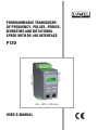
PROGRAMMABLE TRANSDUCER
OF FREQUENCY, PULSES, PERIOD,
WORKTIME AND ROTATIONAL
SPEED WITH RS-485 INTERFACE
P12O
45 120 100 mm
,
USER S MANUAL
1
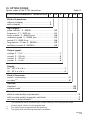
CONTENTS
PAGE
1. APPLICATION ...............................................................................................3
2. SET OF THE P12O TRANSDUCER ..............................................................4
3. BASIC REQUIREMENTS, OPERATIONAL SAFETY ...................................5
4. INSTALLATION .............................................................................................6
5. SERVICING....................................................................................................9
6. RS-485 INTERFACE ....................................................................................28
7. TECHNICAL DATA ......................................................................................45
8. BEFORE A DAMAGE WILL BE SUBMITTED ............................................48
9. EXAMPLES OF P12O TRANSDUCER PROGRAMMINGS .......................50
10. OPTION CODES AND ORDERING............................................................53
11. MAINTENANCE AND GUARANTEE ..........................................................55
2
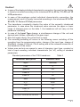
1. APPLICATION
The P12O programmable transducer is designed to convert number of pulses,
number of turns, number of working hours, frequency, period and rotational speed
into a standard d.c. current or d.c. voltage signal.
The output is galvanically isolated from the input and supply.
The P12O-2 transducer has an LCD 2 x 8 read-out field.
The P12O transducer is programmed in the factory according the ordered execution
code. The parameter modification is possible with the user through the PD14 programmer, the RS-485 interface or from the keyboard (in case of P12O-2 option).
The PD14 programmer (must be ordered separately), serves to program the P11
and P12 transducer families.
The P12O transducer realizes the following functions:
- conversion of the measured value into any optional output signal on the base
of the individual linear characteristic,
- recalculation of the input signal into any indication on the base of the
individual linear characteristic,
- signalling of the set alarm value exceeding,
- recording of the input signal in programmed time periods,
- programming of the indication resolution (only for P12O-2 option),
- preview of set parameter values,
- re-calibration of the input signal: multiplication, division by a constant,
- counting of pulses, down and up,
- automatic reset of counters at the required value,
- possibility of external reset, stoppage and start of counters,
- automatic set-up of the decimal point, (in P12O-2 execution),
- programmable digital filter of the input signal (e.g. to eliminate
the effect of contacts oscillation)
- storage of counters state in case of the decay of the supply voltage,
- storage of maximal and minimal values,
- programming of the measurement averaging time,
- display of the unit according the table 1,
- lead-out to supply sensors (24 V d.c.),
- service of the RS-485 interface in the MODBUS protocol, both in ASCII
either in RTU mode,
- data protection by means of a password.
3
a)
b)
O
O
socket
RS-485
Programmer
Socket
socket
RS-485
Programmer
Socket
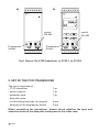
Fig.1 View of the P12O transducer: a) P12O-1, b) P12O-2
2. SET OF THE P12O TRANSDUCER
The set is composed of:
- P12O transducer
- service manual
- guarantee card
- plug with screw
or self-locking terminals (on request)
- hole plug of the programmer socket
1 pc
1 pc
1 pc
4 pcs
2 pcs
When unpacking the transducer, please check whether the type and
execution code on the data plate correspond to the order code.
4
3. BASIC REQUIREMENTS AND OPERATIONAL SAFETY
Symbols located in this service manual mean:
Especially important, one must acquaint with this before connecting the
transducer. The non-observance of notices marked by these symbols
can occasion the damage of the transducer.
One must pay attention when the transducer is working contrary to the
expectations.
In the range of operational safety the transducers are in conformity with the
EN 61010-1 standard requirements.
Remarks concerning the operator safety
A qualified personnel should operate the installation and transducer connection.
One must take into consideration all accessible protection requirements.
Before switching the instrument on, one must check the correctness of the
network lead connection.
In case of the protection terminal connection with a separate lead one must
remember to connect it before the connection of network leads.
Do not connect the instrument to the network through an auto-transformer.
Before taking the transducer housing out, one must turn the supply off.
The removal of the transducer housing during the guarantee contract period
may cause its cancellation.
The programmer socket is designed for connection the PD14 or PD11 programmer
only.
The RS-485 socket is designed for connection devices working with the
MODBUS protocol only.
Place hole plugs into the unused transducer sockets (of the programmer and
RS-485).
5
4. INSTALLATION
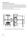
4.1 Fitting of the P12O transducer
P12O transducers are designed to be installed on a 35 mm DIN rail acc.
DIN EN 60715:2002. The housing is made of a self-extinguishing thermoplastics. The
housing dimensions are: 45 x 120 x 100 mm. On the external side of the transducer,
there are screw or self-locking (on order) terminal strips enabling the connection
of 2.5 mm2 cross-section conductors.
Overall dimensions and the fixing way are shown on the fig.2.
41
93
120,7
35
120
P12U
O
RS-485
PD14
45
lock
100
Fig.2. Overall dimensions and fixing way of P12O transducers
6
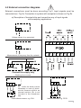
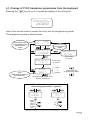
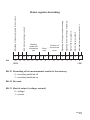
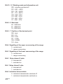
4.2 External connection diagrams
External connections must be done according Fig.3. Input signals must be
connected acc. Fig.3a. Connection in system with computer is shown on Fig.3b.
a) Description of terminal strip and connection way of input signals
with exemplary applications
Voltage sensor (e.g. generator).
Measurement of frequency from the network.
Connect the supply only.
Working hour counter.
Rx - settle the diode current
necessary in case of photoelectric sensors without an
internal resistor (Rx is not
included in the transducer
set).
Photo-electric sensor, e.g. CN1.
Inductive sensor, e.g. PCID.
7
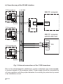
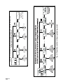
b) Conection way of the RS-485 interface
P12 transducer
A B GND
RS-485 socket
1
IBM PC computer
2
3
4
6
6 7
A
B
5
4
3
2
1
USB
USB
P12 transducer
RS-485 socket
1
PD10
2
3
4
IBM PC computer
with RS-485 card
6
6 7
B
6
1
A
P12 transducers
RS-485 socket
1
DB9
GND
9
5
2
3
4
6
6 7
Fig. 3. External connections of the P12O transducer
Due to the electromagnetic interference, screen conductors are recommended,
to connect signals of the analogue output. Power supply should be connected by
a 2-wire conductor with the proper diameters for ensuring its protection by means
of an installation cut-out.
8
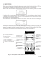
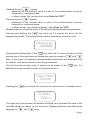
5. SERVICING
After connecting external signals and power supply, what is indicated by a LED on,
the transducer displays the type and the current version of the program.
After ca 3s, the transducer automatically transits into the working mode, in which
P12O
ver 1.00
it realizes the measurement and conversion into an analogue output signal.
It displays the measured value, the unit of the measured or set value by the user
and markers of connected alarms.
The transducer automatically blanks void zeros. The start of the recording is
1,2
50
h
indicated on the display (the mark „M” means the recording is starting, the mark „E”
means the empty memory, however the mark „F” means a full memory). After filling
the memory, the transducer automatically switches the recording off.
M - recording switched on
E - empty memory
F - full memory
LED diode
Indication of the
recording start
Result
Unit
1 - alarm 1 switched on
2 - alarm 1 switched on
1,2 - alarms 1 and switched
on
Indication of the
alarm
Cancellation
key
Value increase
key
Value decrease
key
Acceptation
key
Programmer
connector
4
RS-485
interface
Fig. 4. Description of the P12O transducer frontal plate.
9
Key functions:
- acceptation key
- entry into the programming mode (hold down ca 3 s),
- entry into the change of the parameter value mode,
- acceptation of the modified parameter value.
- value increase key
- display of the maximal value,
- the counter start (if the Exter In=”OFF”)
- moving along the preview menu or on the programming matrix,
- modification of the chosen parameter value - value increasing.
- value decrease key
- display of the minimal value,
- the counter stoppage (if the Exter In=”OFF”)
- moving along the preview menu or on the programming matrix,
- modification of the chosen parameter value - value decreasing.
- cancellation key
- entry into the menu of parameter preview (hold down ca 3 s),
- exit from the preview menu or programming matrix.
- cancellation of the parameter change.
Pressing the keys
and holding down within ca 3 s causes the
erasing of the alarm indication and/or alarm outputs. This operation works
exclusively when the support function is switched on.
Pressing the keys
causes:
- the erasing of the minimal value, in case of the measurement of period,
frequency or rotational speed,
- counters reset and stoppage, in case of the measurement of pulse number,
turns number or in case of the work time counter, when Exter In=”OFF”
Pressing the keys
causes:
- the erasing of the maximal value, in case of the measurement of period,
frequency or rotational speed,
- counters reset and start, in case of the measurement of pulse number, turns
number or in case of the work time counter, when Exter In=”OFF”.
10
Pressing the key
causes:
- displaying of the maximal value in case of the measurement of period,
frequency or rotational speed,
- in other causes, the counter start, when Exter In=”OFF”.
Pressing the key
causes:
- displaying of the minimal value in case of the measurement of period,
frequency or rotational speed,
- in other causes, the counter stoppage, when Exter In=”OFF”.
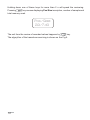
Releasing the key causes the return to the currently displayed measuring parameter.
Pressing and holding the
key within ca 3 s causes the entry into the
programming mode. The programming mode is secured by a security code.
Security
+00000
Pressing and holding down of the
key within ca 3 s cause the entry into the
preview menu. One must move on the preview menu by means of
and
keys. In this menu, all transducer programmable parameters are accessible only
for readout, with the exception of servicing parameters.
The exit from the preview menu is carried out by means of the
possible to review recorded values in the preview menu.
key. It is
View Mem
Enter
Pressing the
key causes the entry into the review menu of recorded value.
15:18:02
502,4
The upper line informs about the sample recording time, whereas the value of the
recorded sample is shown on the lower line. Stepping between recorded values
happens by
and
keys.
11
Holding down one of these keys for more than 2 s will speed the reviewing.
Pressing
key causes displaying Pos/Size inscription, number of sample and
total memory used.
Pos/Size
20/749
The exit from the review of recorded values happens by
key.
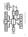
The algorythm of the transducer servicing is shown on the Fig.5.
12
13
Fig. 5. Algorythm of the P12O transducer.
In case of external functions are on Exter In=”On” start, stop and counters reset
is conducted from external lead-outs 4,5,6 (see drawing 3a). Introduce the signal
of voltage range 5...24 V d.c. to „start, stop” terminators, stops the counter. Signal
disconnection starts the counter. Introduce the signal of voltage range 5...24 V d.c.
to „reset” terminator, resets the counter.
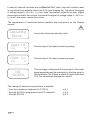
The appearance of mentioned below symbols and inscriptions on the display
means:
Security
Error
Incorrectly introduced security code.
Over. Hi
1,2
V
Overrunning of the higher measuring range.
Over. Lo
1,2
V
Overrunning of the lower measuring range.
NO
SIGNAL
This message in displayed till the moment of the input
signal appearing and its averaging by the time given in
the parameter Cnt. If there is a lack of signal more than
15 s, the transducer displays the value 0.
The change of transducer parameters is possible:
- from the transducer keyboard (in P12O-2)
- through the PD14 programmer and PC computer
- through RS-485
14
- p 5.1.
- p 5.2.
- p 6.5.
5.1. Change of P12O transducer parameters from the keyboard
Pressing the
key for ca 3 s causes the display of the inscription:
Security
+00000
Input of the correct code in causes the entry into the programming mode.
The programming way is shown below:
Exemplary view
of the display in the
measurement
mode
1,2
380
V
Entry into
the programming
mode
3s
Security
+00000
View
of the display with the
first parameter
If the code
is wrong
If the code
is correct
Input
1 00 V
Input
...
Security
OK
Security
Error
Interval
moving on the
programming matrix
Change of the value of the
chosen parameter
Examples of chosen parameter
value change (parameter - symbol)
D_P
00000
00000
0000,0
000,00
00,000
0,0000
Auto
Char. in
Off
On
Off
15
16
0,1
Change of the
flickering position
Cnt
+0000,5
…
Change of the
flickering position
Cnt
+0000,5
Change „+” or „-”
Cnt
+0000,5
Fig. 6. Transition matrix in the programming mode
Change of the
flickering position
Cnt
+0000,1
Cnt
0,5
Blanking
of void zeros
and the „+” mark.
Cnt
Example of chosen parameter value change without the decimal point position
change (numerical parameter)
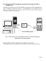
5.2. Change of P12O transducer parameters through the PD14
programmer
The way of connection of the P12O transducer through the PD14 programmer to
the PC computer is shown on the Fig.7. The programmer is connected from one
side to the USB port of the PC computer, and from the other one, through a plug of
RJ12 type to the P12O transducer.
16 x max
8 x max
P12P
O
USB
PD14
RJ 12
PD14
RS-485
Set of the PD14 programmer
Fig. 7. Connection way of the P12O transducer to the PC computer
through the PD14 programmer
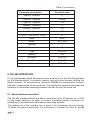
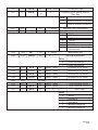
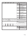
Programmable transducer parameters are specified in the table 1.
The programming of the parameters is possible just after the password entry.
17
Programmable parameters of the P12O transducer
Symbol
on the display
Input
Counter
Input parameters
Filter
100
TypeScal
And
Cons In
10
18
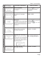
Description of parameters
Input type
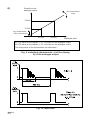
Input filter
The parameter is designed to
filter interferences on the input,
e.g. of the contact oscillation.
The transducer ignores pulses,
shorter than the programmed
time of the filter (Fig.10).
The value of the input filter must
be lower, than the measured
signal frequency.
Table 1
Range of changes
Counter - pulse counter
Frequen. - frequency
Rotary - turns cponter
Tachomet - rotational speed
Period - period
Period H - long period >10 s
TimeMet. - work time counter
Possible settings: 0...99999 ms
And - multiplication by constant
Selection of the re-calibration
Div - division by constant
type of the input quantity.
The measured quantity is multiplied or devided by the introduced
value(Cons In parameter). In
case of the input type selection,
as a counter of pulses, turns
or worktime and multiplication
function, each pulse causes an
increase of the displayed quantity
by the Cons In value.
In case of the input type selection,
as a counter of pulses, turns or
worktime and division function,
each pulse increases by the
1/Cons In value
In case of the left input types, the
measured signal is multiplicated
or devided by the introduced value
(Cons In parameter).
Constant re-calibrating the
input quantity. The negative
value introduction, in case of
counting pulses, number of
turns and worktime, causes the
counting down.
Possible settings: -99999...99999
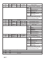
Table 1 (continuation)
Exter In
On
Auto
100
Input parameters
D_P
0000,0
Cnt
0,1
Unit
V
Permission for external functions: start, stop, delay
Automatic resetting of the
counters. The counter is automatically reset by the introduced
number. In case of frequency,
rotational speed and period
measurement, this parameter is
not taken into consideration.
Off - external functions are
switched off
On - external functions are
switched on
Possible settings 0...99999
Setting of the decimal point.
The setting operates either when
the individual characteristic is
switched off or on.
The introduction of the decimal
point, which makes impossible
the display of 7 characters („+”
or „-”, 5 characters for the result,
the decimal point character) on
the display, will cause the display
of the low or upper exceeding.
Possible settings:
Auto - automatic selection of
the decimal point
Time of the measurement
averaging.
0.0...9999.9 s
The write of 0 causes the measurement switching off and
the stoppage of the transducer
work (the LED is switched on).
The current time is displayed
on the display.
Selection of the unit
Possible settings:
V, A, PV, mV, kV, MV, PA, mA,
kA, MA, mW, W, kW, MW, var,
kvar, Mvar, VA, kVA, MVA,oC,
o
F, K, Hz, kHz, MHz, mAh, Ah,
kAh, Wh, kWh, MWh, m/s, (Pm,
mm, cm, m, km, m2, m3, m2/s,
m2/min, m2/h, m3/s, m3/min,
m3/h, l, l/s, l/min, l/h, l/m2, l/m3,
kg/s, kg/min, kg/h, ms, s, h,
mN, N, kN, Pa, hPa, kPa, MPa,
mmHg, bar, rad, m:, :, k:,
M:, G:, %, o, turns, rps, rpm,
rph, m/h, km/h, GW, Gvar,
GVA, GWh,Varh, kVarh, MVarh,
GVarh, VAh, kVAh, MVAh,
GVAh, pulse, pulse/s, pulse/m,
pulse/h.
00000
0000.0
000.00
00.000
0.0000
19
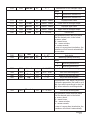
Table 1 (continuation)
Symbol
on the display
X1 In
0,0000
X2 In
0,0000
Alarm 1 and alarm 2 parameters
Y2 LCD
0,0000
20
The switching off or on the user’s On - characteristic
switched on,
individual linear characteristic
Off
characteristic
- („individual characteristic of
switched off.
the display”)
Parameters of the individual
characteristic of the display.
Based on user defined coordinates of two points, the transducer
determines (from the system of
equations) coefficients a and b
of the individual characteristic:
Y1LCD = a · X1In + b
Y2LCD = a · X2In + b
where:
X1 In and X2 In - measured
value
Y1 LCD and Y2 LCD - expected
value on the display.
Fig.9. presents the operation
way of the individual characteristic.
Possible settings:
-99999...99999
e
th stic
en eri
wh ct
e ra on
bl a d
si ch he
ce al itc
Ac vidu sw
di is
Y1 LCD
0,0000
Range of changes
in
Input parameters
Char. In
On
Description of parameters
Low A11
0,0
Alarming lower threshold
-99999...99999
Alarming upper threshold
-99999...99999
Low A12
200,0
High A11
20,0
High A12
300,0
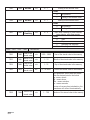
Table 1 (continuation)
Symbol
on the display
Alarm 1 and alarm 2 parameters (continuation)
Type A11
Normal
DelayA11
0,0
DelayA11
5,0
Hold A11
Off
Char.Out.
Off
Range of changes
Type of alarm
Fig.8. presents types of alarms.
Normal - normal,
On - switched on,
Off - switched off.
Hand on - switched on manually; up to the time of changing
the alarm type remains switched
on for good.
Hand off - Switched off manually; up to the time of changing
the alarm type remains switched
off for good.
Delay of alarm operation
The parameter is defined in
seconds, ie one must give after how many seconds from its
occurrence, the alarm operation
will follow. The alarm operation
occurs after the measurement
averaging. The alarm switching-off
follows without delay.
0.0...9999.9
The introduction of 0.0 causes
the operation at the moment of
the alarm occurrence.
The maintenance of the alarm
indication. In the situation when
the maintenance function is
switched on after the withdrawal
of the alarm, state on the display
and/or the contact state does not
change. It signals the alarm state
till the moment of its termination
by means of the key combination
and
.
Off - Maintenance switched off,
The switching on or off of
the user’s individual linear
characteristic - („ the individual
characteristic of the analogue
output”).
On - characteristic switched
on,
Off - characteristic switched
off
Type A12
On
Hold A12
Relay
Output parameters
Description of parameters
LCD - Maintenance of the alarm
signalling on the display,
Relay - maintenance of the
alarm relay,
LCD+Rel - maintenance of the
alarm indication on
the display and the
alarm relay.
When the characteristic is
switched off, the transducer
operates in maximal range
depended on kind of the output
and input.
21
Table 1 (continuation)
X1 LCD
0,0
Output parameters (continuation)
Y2 Out.
0,0
Baud.
9600 b/s
Mode
RTU 8N2
Address
1
22
e
th stic
en eri
wh ct
e ra on
bl a d
si ch he
ce al itc
Ac vidu sw
di is
X2 LCD
0,0
in
Y1 Out.
0,0
Parameters of the individual Possibilities of settings:
characteristic of the analogue -99999...99999
output.
Based on user defined coordinates of two points, the transducer
determines (from the system of
equations) coefficients a and b of
the individual characteristic.
Y1 Out = a · X1 LCD + b
{Y2
Out = a · X2 LCD + b
where:
X1 LCD and X2 LCD - displayed
value,
Y1 Out and Y2 Out - expected
value on the analogue output.
Fig. 9. presents the operation
way of the individual charac-
Baude rate of the RS-485
interface
2400 b/s
4800 b/s
9600 b/s
Kind of transmission through
the RS-485 interface
Off - interface switched off
ASCII 8N1
ASCII 7E1
ASCII 7O1
RTU 8N2
RTU 8E1
RTU 8O1
RTU 8N1
Device address
0...247
Table 1 (continuation)
Symbol
on the display
Servicing parameters
ParFact
Enter
Security
0
Test
LCD
Time
17:18:00
Recording parameters
Memory
Off
Description of parameters
Range of changes
Factory parameters
Pressing
key causes
Factory parameters are presented the registration of factory
in the table 2.
parameters.
Introduction of a new password
-99999...99999
Display test
The display test is expressed
by lighting of the first line LCD
segments, and next the whole line.
The same test is carried out for the
second line.
Pressing
key causes the
test switching on.
key ends
Pressing
the test.
Setting of the current time.
Time format: hh:mm:ss
00:00:00 ... 23:59:59
Switching the recording on
or off.
At the moment of the recording
switching on, the transducer
erases the previous memorised values after exiting from the
programming matrix.
On - recording switched on
Off - recording switched off
Erasing
Wait. . .
StartMem
15:18:23
Recording start time.
Time format: hh:mm:ss
00:00:00 ... 23:59:59
23
DateMem
22.05.01
Interval
01:00:00
00.00.00 ... 99.12.31
Recording start date.
Date format: yy.mm.dd
It is an informative parameter. Not
used to set a date, from which
the recording is to start, but only
informs, when the recording
started.
Recording time interval.
00:00:00 ... 99:59:59
Defines time period, how often the
result should be saved.
Writing format: hh:mm:ss
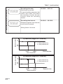
State of contacts
Recording parameters (continuation)
Table 1 (continuation)
a) Normal (High Al > Low Al)
1
1 - Relay switched on
0 - Relay switched off
0
State of contacts
lowerupperalarm threshold
b) Normal (High Al < Low Al)
1
1 - Relay switched on
0 - Relay switched off
0
upperloweralarm threshold
24
Measured value
Measured value
State of contacts
c) Off
1
1 - Relay switched on
0 - Relay switched off
0
Measured value
State of contacts
lowerupperalarm threshold
d) On
1
1 - Relay switched on
0 - Relay switched off
0
Measured value
lowerupperalarm threshold
Fig. 8. Alarm types: a), b) normal c) switched off d) switched on.
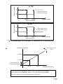
a)
Displayed quantity
Any characteristic
slope
Y2 LCD
Y1 LCD
Any displacement
of the characteristic
X1 In
X2 In
Measured quantity
X1 In value on the transducer input => Y1 LCD value on the display
X2 In value on the transducer input => Y2 LCD value on the display
The other points of the characteristic are calculated.
25
b)
Quantity on the
analogue output
Any characteristic
slope
Y2 Out
Y1 Out
Any displacement
of the characteristic
X1 LCD
X2 LCD
Displayed value
X1 LCD value on the display => Y1 out value on the analogue output
X2 LCD value on the display => Y2 out value on the analogue output
The other points of the characteristic are calculated.
Fig .9. Individual characteristic: a) of the display,
b) of the analogue output.
Fig .10. Input filter.
26
Caution!
In case of the display individual characteristic connection, the result on the display
is linearly converted according to the introduced X1 In, X2 In, Y1 LCD and Y2
LCD parameters.
In case of the analogue output individual characteristic connection, the
measurement result is linearly converted according to the introduced X1 LCD,
X2 LCD, Y1 Out and Y2 Out parameters.
The transducer constantly checks the value of the currently introduced
parameter. In case when the introduced value overruns the upper or lower
range of changes given on the table 1, the transducer will not carry out the
parameter recording.
In case of the Input Type change, a simultaneous change of the unit and
decimal point follows, optimally to the given input.
After the supply decay, the current time is reset.
The recording switching off occurs in the following cases: switching off the
recording from the programming matrix, change of the input type, change of
StartMem, change of Interval, Cnt=0 setting and at the renewed connection of
the transducer to the mains.
Values max and min are erased in case of changing: input type, constant or
kind of input rescaling, individual characteristic (on, off), writing of standard
parameters.
Standard parameters of the P12O transducer
Table 2
Parameter description
Standard value
Input
Tachomet
Filter
0
TypeScal
Div
Cons In
1
Exter In
Off
Auto
99999
D_P
Auto
Cnt
1.0
Char. In
Off
Unit
rpm
X1 In,Y1 LCD,X2 In,Y2 LCD
0
27
Table 2 (continuation)
Parameter description
Standard value
Low Al1, Low Al2
0
High Al1, High Al2
99999
Type Al1, Type Al2
Off
DelayAl1, DelayAl2
0
Hold Al1, Hold Al2
Off
Char. Out
Off
X1 LCD, Y1 Out, X2 LCD, Y2 Out
0
Baud
9600
Mode
RTU 8N2
Address
1
Security
0
Time
00:00:00
Memory
Off
StartMem
00:00:00
DateMem
70.01.01
Interval
00:15:00
6. RS-485 INTERFACE
P12 programmable digital transducers have a serial link in the RS-485 standard
for the communication in computer systems and with other devices fulfilling the
Master function. An asynchronous character MODBUS communication protocol
has been implemented on the serial link. The transmission protocol describes the
manners of information exchange between devices through the serial link.
6.1. Serial interface connection
The RS-485 standard allows the direct connection up to 32 devices on a 1200
m long single serial link. In order to connect a greater number of devices it is
necessary to use additional intermediary-separating systems.
The leading out of the interface line is given in the transducer service manual.
To obtain a correct transmission it is necessary to connect the lines A and B
28
in parallel to their equivalents in other devices. The connection must be carried
out by means of shielded conductors. The shield must be connected to the
protective terminal in a single point. The GND line serves to the extra protection of
the interface line in case of long connections. One must connect it to the protective
terminal (this is not necessary for a correct interface operation).
To obtain the connection with IBM PC class computer, a converter USB into
RS-485 of PD10 type (produced by LUMEL S.A.) or an RS-485 interface card is
essential.
The connection way of P12 transducer through a PD10 converter is presented
on Fig.3.
The identification of transmission lines for the card in the PC computer depends
on the card producer.
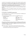
6.2. Description of the MODBUS implementation
The implemented protocol is in compliance with the specification PI-MODBUS-300
Rev G of the Modicon Company.
List of parameters of the transducer serial link in the MODBUS protocol:
• transducer address
- 1...247
• baud rate
- 2400, 4800, 9600 bit/s
• information unit
- ASCII, RTU
• working mode
- ASCII: 8N1, 7E1, 7O1
- RTU: 8N2, 8E1, 8O1, 8N1
• maximal response time
- 300 ms
The parameter configuration of the serial link is described in the futher part of
the service manual. This configuration consists on the settlement of the baud
rate (Baud parameter), device address (Address parameter) and the type of the
information unit (Mode parameter).
Note: Each transducer connected to the communication network must have:
• a unique address , different from the other devices connected to the network.
• the same baud rate and type of the information unit.
29
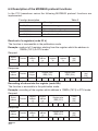
6.3 Description of the MODBUS protocol functions
In the P12 transducer series the following MODBUS protocol functions are
implemented:
Function description
Table 3
Code
Meaning
03 (03 h)
06 (06 h)
16 (10 h)
17 (11 h)
Read-out of n-registers
Recording of a single register
Recording of n-registers
Identification of the slave device
Read-out of n-registers (code 03 h)
The function is inaccessible in the publication mode.
Example: read-out of 2 registers starting from the register which the address is
1DBDh (7613) in RTU mode.
Request:
Device
address
Function
01
03
Register
address
Hi
1D
Register
address
Lo
BD
Number of
registers
Hi
00
Number of
registers
Lo
02
Control
total
CRC
52 43
Response:
Device
address
Function
Number
of bytes
01
03
08
Register value
1DBD (7613)
3F
80
00
Register value
1DBE (7614)
00
40
00
00
00
Control
total
CRC
42 8B
Recording of values into the register (code 06h)
The function is accessible in the publication mode.
Example: recording of the register which address is 1DBDh (7613) in RTU mode.
Request:
Device
address
Function
01
06
Register
address
Hi
1D
Register
address
Lo
BD
Register
address
Hi
1D
Register
address
Lo
BD
00
Control
total
CRC
85 AD
00
Control
total
CRC
85 AD
Register value
1DBD (7613)
3F
80
00
Response:
Device
address
Function
01
06
30
Register value
1DBD (7613)
3F
80
00
Recording into n-registers (code 10h)
The function is accessible in the publication mode
Example: recording of 2 registers starting from the register which address
is 1DBDh (7613) in RTU mode.
Device
address
Function
Request:
01
10
Register
address
Hi
Lo
1D BD
Number of
registers
Hi
Lo
00
02
Number Value for the register Value for the register
1DBD (7613)
of bytes
1DBE (7614)
08
3F 80 00 00 40 00 00 00
Control
total
CRC
03 09
Response:
Device
address
01
Function
Register
address
Hi
Register
address
Lo
10
1D
BD
Number of Number of
registers registers
Hi
Lo
00
02
Control
total
(CRC)
D7 80
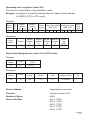
Report identifying devices (code 11h) in RTU mode.
Request:
Device
address
Function
01
11
Control total
(CRC)
C0 2C
Response:
Device
address
Function
Number
of bytes
Device
identifier
Device
state
Field depending on
the type of device
01
11
08
73
FF
4FXXXXX
Device address
- depending on set value
Function
- function number 0x11
Number of bytes
- 0x08
Device identifier
- 0x71 - P12H
- 0x72 - P12S
- 0x74 - P12U
- 0x73 - P12O
- 0x79 - P12P
Control
total
31
Device state
- 0xFF
Field depending on the device type
- XXXXXX
Device name
- transmitted as a ASCII character
and defines the type of transducer
H - 0x48, 48 X X X X X
S - 0x53, 53 X X X X X
U- 0x55, 55 X X X X X
O - 0x4F, 4F X X X X X
P - 0x50, 50 X X X X X
Analogue output
- field depending on the type of the
analogue output
- 0x00 - voltage analogue output,
X 00 X X X X
- 0x01 - current analogue output,
X 01 X X X X
No. of the software version
- software version implemented
into the transducer
- X X_ _ _ _4-byte variable of the
floating type
Control total
- 2 bytes in case of work in RTU mode
- 1 byte in case of work in ASCII mode
Example:
Work in RTU mode, e.g.: Mode = RTU 8N2 (value 0x02 in read/recording case
through the interface).
P12O transducer
Execution with a voltage analogue output: 00,
No. of the software version: 1.00,
Device address set on: Address = 0x01,
For such a type of transducer the frame has the following form:
Device
address
Function
Number
of bytes
Device
identifier
Device
state
Field depending of the
device type
Control
total
(CRC)
01
11
08
73
FF
4F 00 3F 80 00 00
7E 75
32
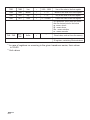
6.4. P12 transducers register map
P12 transducers register map
Table 4
Address
range
Type of value
Description
7000-7200
Float (32 bits)
The value is placed in two successive 16-bit
registers. Registers enclose the same data as
32-bit registers from the 7500 area.
Registers are only for read-out.
7200-7400
Float (32 bits)
The value is placed in two successive 16-bit
registers. Registers enclose the same data as
32-bit registers from the 7600 area.
Registers can be read out and recorded.
7500-7600
Float (32 bits)
The value is placed in a 32-bit register.
Registers are only for read-out.
7600-7700
Float (32 bits)
The value is placed in a 32-bit register.
Registers can be read out and recorded.
33
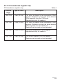
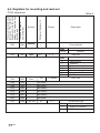
6.5. Registers for recording and read-out
The value is placed in
a 32-bit register.
7200
7600
Table 5
Symbol
Identifier
Writing (w)/ Read-out (r)
The value is placed in two
successive 16-bit registers.
Registers enclose the same
data as 32-bit registers from
the 7600 area.
P12O transducer
r
Range
Description
-
Device identifier
Value
0x73h
7202
7601
Input
w/r
0... 6
Identifier
Input type
Value
0
1
2
3
4
5
6
Filter
w/r
7204
7602
7206
7603
No occurs1)
7208
7604
No occurs1)
7210
7605
No occurs1)
7212
7606
No occurs1)
7214
7607
No occurs1)
7216
7608
No occurs1)
7218
7609
Type Scal
w/r
Pulse number
Frequency
Turns number
Rotational speed
Period
Long period > 10s
Work time counter
0...99999
Input filter
0...1
Re-calibration type
Value
0
1
34
Division by constant
Multiplication by constant
7220
7610
Cons In
w/r
7222
7611
Exter In
w/r
-99999...99999
0...1
Re-calibration type
Premission for an external function:
Start, Stop
Value
7224
7226
7612
7613
7228
7614
7230
7615
Auto
D_P
Cnt
Char.In
w/r
0...99999
0... 5
w/r
0
External functions switched off
1
External functions switched on
Automatic reset of the counters
Decimal point
Value
0
1
2
3
4
5
w/r
0... 9999.9
Measurement time
0... 1
w/r
00000
0000.0
000.00
00.000
0.0000
automatic selection of the
decimal point
Individual characteristic
Value
0
Charac. switched off
1
Charac. switched on
7232
7616
X1 In
w/r
- 99999... 99999
Parameters of ind. charac.
7234
7617
Y1 LCD
w/r
- 99999... 99999
Parameters of ind. charac.
7236
7618
X2 In
w/r
- 99999... 99999
Parameters of ind. charac.
7238
7619
Y2 LCD
w/r
- 99999... 99999
Parameters of ind. charac.
7240
7620
7242
7621
Low AL1
w/r
- 99999... 99999
Lower threshold of alarm 1
7244
7622
High AL1
w/r
- 99999... 99999
Upper threshold of alarm 1
7246
7623
Type AL1
w/r
0... 4
Alarm 1 type
No occurs
1)
Value
0
Normal
1
Switched on
2
Switched off
3
Manually switched on
4
Manually switched off
35
7248
7624
Delay AL1
w/r
0... 9999.9
Delay of alarm 1
7250
7625
Delay AL1
w/r
0... 3
Holding of the alarm 1 signalling
Value
0
Holding switched off
1
Signalling on LCD
2
Relay holding
3
Signalling on LCD and
relay holding
To erase the alarm holding, one must
switch the holding off (0 value) and then
return to the previously set value.
No occurs1)
7252
7626
7254
7627
Low AL2
w/r
- 99999... 99999
Lower threshold of alarm 2
7256
7628
High AL2
w/r
- 99999... 99999
Upper threshold of alarm 2
7258
7629
Type AL2
w/r
0... 4
Alarm 2 type
Value
0
Normal
1
Switched on
2
Switched off
3
Manually switched on
4
Manually switched off
7260
7630
Delay AL2
w/r
0... 9999.9
Delay of the alarm 2
7262
7631
Hold AL2
w/r
0... 3
Holding of the alarm 2 signalling
Value
0
Holding switched off
1
Signalling on LCD
2
Relay holding
3
Signalling on LCD and
relay holding
To erase the alarm holding, one must
switch the holding off (0 value) and then
return to the previously set value.
7264
7632
No occurs1)
7266
7633
No occurs1)
7268
7634
No occurs1)
36
7270
7635
Char.Out
w/r
0... 1
Characterisic of the analogue output
Value
7272
7636
7274
7637
7276
0
Characterisic switched off
1
Characterisic switched off
w/r
-99999... 99999
Displayed lower value
Y1 Out
w/r
-99999... 99999
Lower value of analogue output
7638
X2 LCD
w/r
-99999... 99999
Displayed upper value
7278
7639
Y2 Out
w/r
-99999... 99999
Upper value of analogue output
7280
7640
Time
w/r
0... 23.5959
Current time
This parameter occurs with four places
after the decimal point, in the format
gg,mmss, where:
gg - means hours,
mm - means minutes,
ss - means seconds.
In case of a wrong time introduction, the
transducer will not correct automatically
the new value.
7282
7641
Unit
w/r
0... 972)
Unit choice
7284
7642
Mem. type
w/r
0... 1
Measuring quantity recording
Value
0
Recording switched off
1
Recording switched on
7286
7643
Interval
w/r
0... 99,5959
Time period of the recording
7288
7644
Year
w/r
1970... 2038
Year of the recording start
7290
7645
Month
w/r
1... 12
Month of the recording start
7292
7646
Day
w/r
1... 31
Day of the recording start
The parameters: Year, Month, Day are only
informative parameters. Not used to set a
date, from which recording is to start, but
only inform when the recording started.
7294
7647
Mem.start
w/r
0... 23.5959
Time of the recording start
This parameter occurs with four places
after the decimal point in the format
gg, mmss, where:
gg - means hours,
mm - means minutes,
ss - means seconds.
In case of a wrong time introduction, the
transducer will correct it automatically.
37
7296
7648
Del.Min
w/r
0... 1
Erasing of the minimal value
Value
7298
7649
Del.Max
w/r
0
No operation
1
Erasing of the minimal value
0... 1
Erasing of the maximal value
Value
7300
7650
Start/Stop/
Resetting
w/r
0... 3
0
No operation
1
Erasing of the maximal value
Start, stop, resetting of: pulse counter,
turns counter, work time counter
Value
0
1
2
3
7302... 7310
7320
7322
7651... 7655
Start
Stop
Resetting and stoppage
Resetting and start
No occurs1)
Year of the
stored value
Month of the
7661
stored value
7660
w/r
1970... 2038
Year of the stored value in the memory
w/r
1... 12
Month of the stored value in the memory
7324
7662
Day of the
stored value
w/r
1... 31
Day of the stored value in the memory
7326
7663
Time of the
stored value
w/r
0... 23.5959
Time of the stored value in the memory
This parameter occurs with four places
after the decimal point in the format
gg, mmss, where:
gg - means hours,
mm - means minutes,
ss - means seconds.
In case of a wrong time introduction, the
transducer will correct it automatically.
7328
38
7664
Index of the
stored value
w/r
1... 750
Number of the stored value in the memory
7330
7665
Status
w/r
0... 7
Status of the operation in the buffer
Value
7332
7666
Number
of the
stored value
r
0... 750
0
No operation
1
Search acc. the date and time
(registers 7660...7663
and 7320...7326)
2
Search acc. the time
(registers 7663 and 7326)
3
Search acc. the index
(registers 7664 and 7328)
4
Load next values into the
buffer
(registers 7672...7691
and 7344...7382)
5
Load previous values into the
buffer
(registers 7672...7691
and 7344...7382)
6
Go to the first stored value
in the memory
7
Go to the last stored value
in the memory
Number of the stored value into the memory, placed in the first buffer register
Value
0
The memory is empty
1... 750 Number of the stored value
7334
7667
Number
of recorded
register
r
0... 750
Number of the recorded buffer register
Value
0
The buffer is empty
1... 750 Number of recorded registers
39
7336
7668
Year
r
1970... 2038
Year of the value in the first register
7338
7669
Month
r
1... 12
Month of the value in the first register
7340
7670
Day
r
1... 31
Day of the value in the first register
7342
7671
Time
r
0... 23.5959
Time of the value in the first register
This parameter occurs with four places
after the decimal point in the format
gg, mmss, where:
gg - means hours,
mm - means minutes,
ss - means seconds.
7344...7382
7672...
7691
Buffer
r
–
Stored value, read-out from the memory
20 registers, containing 20 stored values
1)
In case of registers no occurring in the given transducer series, their values
is 1E+20
2)
Unit values
40
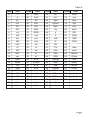
Table 6
Code
Unit
Code
0
1
2
3
4
5
6
7
8
9
10
11
12
13
14
15
16
17
18
19
20
21
22
23
24
V
A
PV
mV
KV
MV
PA
mA
kA
MA
mW
W
kW
MW
var
kvar
Mvar
VA
kVA
MVA
C
F
K
Hz
kHz
25
26
27
28
29
30
31
32
33
34
35
36
37
38
39
40
41
42
43
44
45
46
47
48
49
Unit
MHz
mAh
Ah
kAh
Wh
kWh
MWh
m/s
Pm
mm
cm
m
km
m2
m3
m2/s
m2/min
m2/h
m3/s
m3/min
m3/h
l
l/s
l/min
l/h
Code
Unit
50
51
52
53
54
55
56
57
58
59
60
61
62
63
64
65
66
67
68
69
70
71
72
73
74
l/m2
l/m3
kg/s
kg/min
kg/h
ms
s
h
mN
N
kN
Pa
hPa
kPa
MPa
mmHg
bar
rad
mOhm
Ohm
kOhm
MOhm
GOhm
%
Code
75
76
77
78
79
80
81
82
83
84
85
86
87
88
89
90
91
92
93
94
95
96
97
Unit
turns
rps
rpm
rph
m/h
km/h
GW
GVar
GVA
GWh
Varh
karh
MVarh
GVarh
VAh
kVAh
MVAh
GVAh
pulse
pulse/s
pulse/m
pulse/h
41
6.6. Registers only for read-out
The value is placed in
32-bit registers
7000
7500
Table 7
Name
Unit
Name of the quantity
Writing (w)
/read -out (r)
The value is placed in two
successive 16-bit registers.
Registers enclose the same
data as 32-bit registers from
the 7500 area
P12O transducer
r
Identifier
-
Constant identifying the device
0x73 - P12O
7002
7501
Status
r
-
Status is the register describing the
transducer current state
7004
7502
Steering
r
%
It is the register describing the steering
of the analogue output
7006
7503
Min
r
-
Minimal value of the currently measured
value
7008
7504
Max
r
-
Maximal value of the currently measured
value
7010
7505
Measured
value
r
-
Currently measured value on the
transducer
7012
7506
No occurs1)
7014
7507
Hour
r
gg, mmss
7016
7018... 7096
1)
7508
Current time
1)
No occurs
1)
7509... No occurs
7548
In case of registers no occurring in the given transducer series, their values
is 1E+20
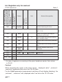
Caution!
While exceeding the upper or the lower range, „ displayed value”, „minimum”,
„maximum” parameters are set on the 1E+20 value.
For the Cnt=0 parameter (measurement switching off and display blanking), the
„minimum”, „ maximum” and „displayed value” are set on the 1E +20 value.
42
Signalling of the lower range exceeding
State of the relay (alarm) 2
State of the relay (alarm)1
Individual characteristic or lack of it
X
X
X
X
X
X
X
X
X
X
X
15 14 13 12 11 10
9
8
7
6
5
4
3
2
1
0
X
bits
Kind of output (voltage, current)
Signalling of the upper range exceeding
Recording of measuring results in the memory
Status register describing
X
X
Working
mode and
information
unit
X
X
Baud
rate
Position of
the decimal
point
MSB
LSB
Bit-15 Recording of the measurement results in the memory
0 - recording switched off
1 - recording switched on
Bit-14 No used
Bit-13 Kind of output ( voltage, current)
0 - voltage
1 - current
43
Bit-12...10 Working mode and information unit
000 - interface switched off
001 - 8N1 - ASCII
010 - 7E1 - ASCII
011 - 701 - ASCII
100 - 8N2 - RTU
101 - 8E1 - RTU
110 - 8O1 - RTU
111 - 8N1 - RTU
Bit-8...9 Baud rate
00 - 2400 bit/s
01 - 4800 bit/s
10 - 9600 bit/s
Bit-5...7 Position of the decimal point
000 - lack
001 - 0.0
010 - 0.00
011 - 0.000
100 - 0.0000
101 - Auto
Bit-4 Signalling of the upper overrunning of the range
0 - normal work
1 - range overrunning
Bit-3 Signalling of the lower overrunning of the range
0 - normal work
1 - range overrunning
Bit-2 Relay (alarm) 2 state
0 - switched off
1 - switched on
Bit-1 Relay (alarm)1 state
0 - switched off
1 - switched on
Bit-0 Individual characteristic
0 - individual characteristic switched off
1 - individual characteristic switched on
44
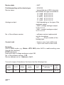
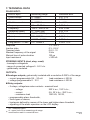
7. TECHNICAL DATA
PULSE INPUT:
Kind of input
Pulse counter
Turns counter
Worktime counter
Frequency
Frequency
Rotational speed
Rotational speed
Period
Period
Long period > 10 sec
Measuring range
0...99999
0...99999 turns
0...99999 h
0.1... 99.99 Hz
100.0...3000,0 Hz
0...10000 rpm
10000...99999 rpm
0.3...999.99 ms
1.0000...9.9999 s
0.5...99999 s
Amplitude
Inactive state
Transient state
Maximal frequency of the signal
Minimal time of pulse duration
Input resistance
Indication error2
0.01 % ul1
0.01 % ul
2 s / 24 hours
0.01 % ul
0.02 % mv
0.02 % ul
0.1 % mv
0.01 % ul
0.02 % ul
0.0001 % ul
1 V...253 V
0 V...0.8 V
0.8 V...1V
3 kHz
150 Ps
> 200 k:
STEERING INPUTS (start, stop, reset):
- transoptor voltageless
- range of connected voltages 5...24 V d.c.
- galvanically insulated
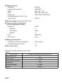
OUTPUTS:
Analogue outputs, galvanically insulated with a resolution 0.025% of the range:
– current programmable 0/4... 20 mA
load resistance x 500 :
– voltage programmable 0...10 V
load resistance 500 :
Relay outputs:
– 2 relays; voltageless make contacts - maximal load:
- voltage
250 V a.c., 150 V d.c.,
- current
5 A, 30 V d.c., 250 V a.c.,
- resistance load
1250 VA, 150 W,
– programmable alarm thresholds,
– three types of alarms,
– hysteresis defined by means of the lower and higher alarm threshold,
– signalling of the alarm operation on the LCD display.
1)
mv - measured value
ul - upper limit of the measuring sub-range
2)
concerns the result in numerical form
45
Digital outputs:
– interface
– transmission protocol
– ASCII
– RTU
– baud rate
– maximal response time to the
query frame
RS-485,
MODBUS,
8N1, 7E1, 7O1,
8N2, 8E1, 8O1, 8N1,
2400, 4800, 9600 baud,
300 ms
Sensor supply (maximal load 30 mA)
Communication parameters
of the programmer socket:
– interface
- data bits
- even parity
- stop bit
– rate
– flow control
UART
8
none
1
9600 bit/s
none
Storage parameters:
– transducer memory (recording)
– minimal recording interval
750 samples
1s
Accuracy class
0.2
Minimal subrange preserving the class.
Table 5.
Kind of input
Minimal subrange preserving the clas
Impulse counter
Turn counter
25
25 turns
Working hour counter
25 h
Frequency
2 Hz
Rotational speed
Period
46
120 rpm
20 ms
Additional error from ambient
temperature changes
Conversion time:
averaging time min 100 ms
(0.1% of the range /10K)
min 200 ms ( measurement
+ output response time = 100 ms)
Rated operating conditions:
– supply voltage depending on the
option code
– supply voltage frequency, a.c.
– ambient temperature
85...230...253 V a.c./d.c.
20...24...50 V a.c./d.c.
40...50...440 Hz
- 20...23...55
C
– storage temperature
- 25...+85
C
– air relative humidity
< 95% (no condensation)
– preheating time of the transducer
10 min
– working position
any
Display field (in P12O-2)
LCD 2 x 8 display
indication range: - 99999... 99999
Servicie (in P12O-2)
four keys:
Ensured protection degree
through the case
Ensured protection degree
from terminal side
Dimensions
IP 40
IP 20
45 x 100 x 120 mm
Mass
< 0.3 kg
Fixing
on a 35 mm DIN rail
Power consumption
< 5 VA
Supply decay immunity
acc. EN 50082-2
Electromagnetic compatibility:
– noise immunity
– noise emission
acc. EN 61000-6-2
acc. EN 61000-6-4
Security requirements
acc. EN 61010-1 standard:
– installation category
III
– pollution level
2
– phase-to-earth maximal working voltage 600 V a.c.
47
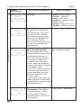
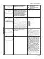
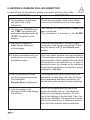
8. BEFORE A DAMAGE WILL BE SUBMITTED
In case of incorrect symptoms, please to acquaint with the below table.
SYMPTOMS
1. The transducer diode does
not light. Lack of any
indications.
2. The time (eg. 12:34:43) and
the „TIME” inscriptions are
alternately displayed with the
„P12O” inscription on the
display.
3. Inscriptions Over.Hi or
Over. Lo are displayed
on the display.
4. A signal inconsistent with our
expectations occurs on the
transducer output.
5. Lack of possibility to enter
into the programming mode.
The inscription
Security Error is displayed.
6. Lack of certainty if all
character fields of the display
are efficient.
48
PROCEDURE
Check the connection of the mains cable.
Connect the transducer to the mains again.
The number of measurements Cnt=0 has
been introduced.
The transducer is working in the SLEEP
Check the correctness of the input signal
connection. See the service manual. Check
also the setting of D_P and Char.In parameters.
One must check whether the load resistance
of the analogue output is compatible with the
technical data. Check whether the individual
characteristic is not switched on. In case of
necessity make the change of the individual
characteristic parameters or introduce factory
parameters: Par.fact.
The programming mode is secured by the
password. In case when the user will forget
which password had been introduced, he
should phone the nearest service workshop.
Enter into the programming matrix and
switch the display test on. The character
fields are successively lighted in the first
line till the lighting of the last field. Then, the
whole line is lighted. This operation is repeated for the second line. If otherwise, submit
the fault to the nearest service workshop.
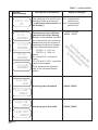
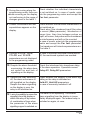
Check whether the individual characteristic
programming mode, there are is not switched on. In case of needs, enter
values occurring on the display, into the programming matrix and accept the
not conforming to the range of Par. fact. parameter.
changes given in the table 1.
7. During the moving along the
8. A result inconsistent with our
expectations appears on the
display.
9. Symbols of X1 In , X2 In,
Y1 LCD, and Y2 LCD
parameters are not displayed
in the programming mode.
Check whether the individual characteristic is
not switched on.
Check also if the introduced input filter value
is correct (filter parameter). Introduction of
longer time, than time between pulses on
input, will cause, that pulses will be considered
as interferences and will not be counted.
In case of needs, enter into the programming
matrix and accept the Par. fact. parameter.
The transducer will introduce parameters acc.
The table 2.
In case of switched individual characteristic
off, the mentioned symbols are avoided.
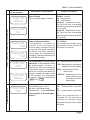
Check the introduced into transducer delay
overrunning, the alarm does of the alarm operation. If possible correct
not switch on and lack of Delay Al1, Delay Al2 parameters.
signalling on the display.
10. Despite the alarm threshold
11. Despite the relay switching
off, the alarm occurrence is
still signalled on the display.
Despite the alarm signalling
on the display is over, the
relay is still switched on.
Check whether the support of the alarm signalling or the relay is switched on.
Hold Al1, Hold Al2 parameters.
In case of necessity switched it off.
12. Lack of possibility to erase the The alarm is still operating. The erased
alarm signalling from the display is immesignalling from the display or
diately displayed again. The erased relay is
switch the relay off by means
switched on again, at once.
of combination of keys when
the parameter of the alarm
signalling support is switched on.
49
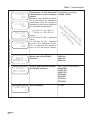
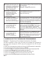
13. Despite the alarm lasts, the
erased alarm signalling from
the display is not displayed
again or/and the relay
remains switched off.
14. Instead of displaying the
measuring result, the
transducer displays the
parameter symbol
and its value.
Check whether a delay of alarm operation was
not introduced.
Delay Al1, Delay Al2 parameters.
The transducer works in the preview mode
or the programming matrix.
Press the erase key.
The persisting alarm state was shorter than
the programmed one, i.e. a state of the alarm
operation was introduced,
retract occurred during the alarm operation. In
e.g. 30 s, but the alarm,
after this time did not operate. that case, the transducer begins to deduct the
time from the beginning.
15. A delay of the alarm
16. The transducer does not
communicate with the
computer through
the RS-485 interface.
17. The transducer does not
communicate with the
computer through
the PD14 programmer.
Check if the interface conductors were correctly connected (A, B, GND). Then, check
the setting of the interface in the programming matrix (Mode, Baud, Address). These
parameters must be the same as in the used
software.
Check whether the PD14 programmer was
correctly connected. Check if in the used
software the proper communication port was
chosen. The programmer works only with
one transducer socket.
9. EXAMPLES OF P12O TRANSDUCER PROGRAMMINGS
Example 1 - Programming of the individual characteristic of the display
We want to program in order to the 0.00 value on the display will correspond to
the 10 Hz value, whereas the 100.00 value will correspond to the 100 Hz value.
One must:
enter into the programming mode and choose the D_P parameter responsible
for the decimal point. Set the decimal point on 000.00
choose the Char. In. parameter and switch the individual characteristic On
choose the X1 IN parameter and introduce the value 10
transit on the Y1 LCD parameter and introduce the value 0.00
transit on the X2 IN parameter and introduce the value 100
transit on the Y2 LCD parameter and introduce the value 100.00
50
Example 2 - Programming of the inverse individual characteristic
If we want to program in order to the 120.5 value on the display will correspond
to the 0 s value, whereas the 10.80 value will correspond to the 100 s value.
One must:
enter into the programming mode and choose the D_P parameter responsible
for the decimal point. Set the decimal point on 0000.0
choose the Char. In. parameter and switched the individual characteristic On
choose the X1 IN parameter and introduce the value 0
transit on the Y1 LCD parameter and introduce the value 120.5
transit on the X2 IN parameter and introduce the value 100
transit on the Y2 LCD parameter and introduce the value 10.8
Example 3 - Alarm programming with hysteresis
If we want to program the alarm 1 in order to at the 1500 rpm value the alarm was
switched on, whereas it was switched off at the 30 rpm, and the alarm 2 operation
in order to at the 0 rpm it was switched off and switched on at the 320 rpm value.
One must:
enter into the programming mode and choose the Low Al1 parameter and
introduce 1500
transit on High Al1 parameter and introduce the value 30
transit on the Type Al1 parameter and choose the function marked as Normal
choose the Low Al2 parameter and introduce 0
transit on the High Al2 parameter and introduce the value 320
transit on the Type Al2 parameter and choose the Normal function
Example 4 - Alarm programming in the set interval with delay
If we want that the alarm 1 was switched on, whereas it was switched on in the
interval from 1000 to 3000 and operated only after 10 seconds, one must:
enter into the programming mode and choose the Low Al1 parameter and
introduce 1000
transit on High Al1 parameter and introduce the 3000 value
transit on the Type Al1 parameter and choose the On function
transit on the Delay Al1 parameter and introduce the value 10.0
In case of continuation of the alarm state for more than 10.0 seconds,the
transducer will switch the alarm relay on or/and indicate this on the display.
Example 5 - Programming of the analogue output
If we want to program in order to the 4.00 mA value on the analogue output will
correspond to the 50 Hz value on the display, whereas the 20.00 mA value will
correspond to the 100 Hz value. One must:
51
enter into the programming mode and choose the Char.Out parameter
and switched on the On individual characteristic
transit on Char. Out parameter and switched on the On individual
characteristic
choose the X1 LCD parameter and introduce the 50 value
transit on Y1 Out parameter and introduce the 4.00 value
transit on the X2 LCD parameter and introduce 100 value
transit on the Y2 Out parameter and introduce the value 20.00
Example 6 - Programming of the transducer for rotational speed conversion.
The transducer works with the sensor by 60 pulse/turn constant.
choose the Tachomet as input type
transit on the Type Scal parameter and set Div
transit on the Cons In parameter and set 60 value
exit from the programming mode
The transducer starts rotational speed processing.
Example 7 - Programming of the pulse counter to count down and after
overrunning 0, again will start the counting from the value 12546.
choose the Counter as input type
transit on the Cons In parameter and set -1 value
transit on the Auto parameter and set 12546 value
exit from the programming mode
The transducer starts the pulse counting from 12456...0 and after overrunning 0,
again will start the counting from 12546...0.
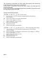
Example 8 - Programming of the input filter to consider all pulses, between
which the distance is shorter than 100 ms, as interferences.
transit on the filter parameter and set 100 value
The transducer starts the counting only pulses, between which the distance
is longer than 100 ms.
The other pulses will consider as interferences.
Example 9 - Programming of the recording every 20 s, from 12:30.
enter into the programing mode and chose the StartMem parameter and
introduce the value 12:30
transit on the Interval parameter and introduce the value 00:00:20
Choose the Memory parameter and switch the rekording On
After exiting from the programming mode, the memory will erased and begin to
record results from 12:30, every 20 s.
After filling the memory, the recording will be switched off.
52
10. OPTION CODES
Option codes of the P12O transducer
P12O PROGRAMMABLE TRANSDUCER
Table 8 .
X
XX
X
X
X
XX
X
Kind of transducer:
without a display ............................................. 1
with a display .................................................. 2
Input signal*:
pulse counter 0...99999 ........................................00
frequency 0.1...3000 Hz ........................................01
turns counter 0...99999 turns.................................02
rotational speed 0...99999 rpm ..............................03
period 0.3...9999.9 ms ............................................04
long period > 10 sec 0...99999 s ............................05
worktime counter 0...99999 h .................................06
Output signal:
voltage 0... 10 V...............................................................1
current 0... 20 mA ...........................................................2
current 4... 20 mA ...........................................................3
current 0... 5 mA .............................................................4
Supply:
85... 253 V a.c./d.c...................................................................1
20... 50 V a.c./d.c.....................................................................2
Kind of terminals:
socket - screw plug ..........................................................................0
on order*** .......................................................................................X
Options:
standard.................................................................................................. 00
custom-made* ........................................................................................XX
Acceptance tests:
without extra quality requirements ...................................................................8
with an extra quality inspection certificate .......................................................7
acc user’s arequirements** .............................................................................X
*
**
***
The transducer has a universal input. When ordering, one must give the code
of input signal, which is to be programmed.
The option must be agreed with the producer.
The option with self-locking terminals is available.
53
The transducer maintains its class when decreasing the measuring
range to the minimal range given in the table 5.
In the P12O-1 transducer, beside the basic range, one must give the
required subrange.
In case when the given subrange is lower than in the table 5, one must precise
the input signal in the order (XX).
Coding and ordering example:
The P12O - 2 - 04 - 3 - 1 - 0 - 00 - 8 code means:
2
- the execution of a P12O transducer programmed by the producer,
with a display
04 - with an input signal for period measurement,
3 - with an output signal : 4...20 mA ,
1 - supply voltage: 85...253 V a.c./d.c.,
0 - with a socket-screw plug,
00 - standard execution,
8 - without extra quality requirements.
The P12O - 1 - 01 - 1 - 1 - 0 - 00 - 8, for a 0.1...100 Hz sub-range code means:
1
- the execution of a P12O transducer programmed by the producer,
without a display
01 - with an input signal for frequency measurement, in the range 0.1...3000 Hz
1 - with an output signal : 0...10 V,
1 - supply voltage: 85...253 V a.c./d.c.,
0 - with a socket-screw plug,
00 - standard execution,
8 - without extra quality requirements.
54
11. MAINTENANCE AND GUARANTEE
The P12O transducer does not require any periodical maintenance.
In case of some incorrect unit operations:
1.From the shipping date, during the period given in the annexed guarantee card:
One should take the transducer down from the installation and return it to the
Manufacturer’s Quality Control Dept.
If the unit has been used in compliance with the instructions, the manufacturer
guarantees to repair it free of charge.
2. After the guarantee period:
One should turn over the transducer to repair in a certified service workshop.
The disassembling of the housing causes the cancellation of the granted guarantee.
Spare parts are available for a period of ten years from the date of purchase.
The Manufacturer’s policy is one of continuous
improvement and we reserve the right to make
changes in design and specifications of any products
as engineering advances or necessity requires and
revise the above specification without notice.
55
P12O-09B
Lubuskie Zak³ady Aparatów Elektrycznych - LUMEL S.A.
ul. Sulechowska 1, 65-022 Zielona Góra, Poland
Tel.: (48-68) 32 95 100 (exchange)
Fax: (48-68) 32 95 101
www.lumel.com.pl
e-mail:[email protected]
Export Department:
Tel.: (48-68) 329 53 02 or 53 04
Fax: (48-68) 325 40 91
e-mail: [email protected]
56