1
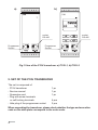
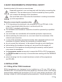
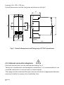
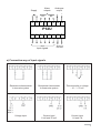
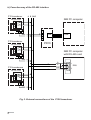
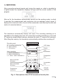
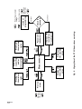
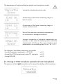
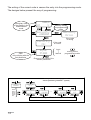
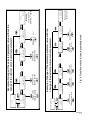
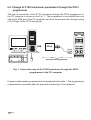
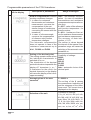
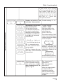
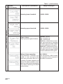
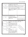
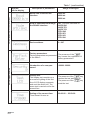
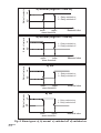
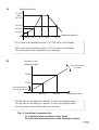
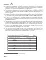
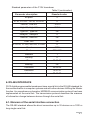
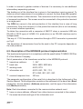
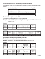
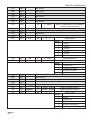
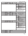
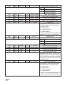
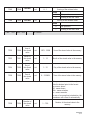
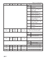
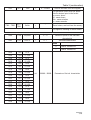
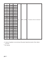
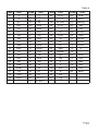
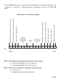
PROGRAMMABLE TRANSDUCER WITH RS-485 INTERFACE (temperature, standard signals, d.c. voltage, d.c.current) P12U 45 120 100 mm , USER S MANUAL 1 CONTENTS PAGE 1. APPLICATION ................................................................................................3 2. SET OF THE P12U TRANSDUCER ..............................................................4 3. BASIC REQUIREMENTS, OPERATIONAL SAFETY ....................................5 4. INSTALLATION ..............................................................................................5 4.1 Fitting of the P12U transducer .................................................................5 4.2 External connection diagrams ..................................................................6 5. SERVICING....................................................................................................9 6. RS-485 INTERFACE ....................................................................................27 7. TECHNICAL DATA .......................................................................................45 8. BEFORE A DAMAGE WILL BE SUBMITTED ..............................................48 9. EXAMPLES OF P12U TRANSDUCER PROGRAMMINGS.........................51 10. EXECUTION CODES AND ORDERING ......................................................53 11. MAINTENANCE AND GUARANTEE ...........................................................56 2 1. APPLICATION The P12U programmable transducer is intended to the conversion of temperature, resistance, voltage from the shunt, standard signals, d.c. voltage and d.c. current into a d.c. standard signal or d.c. voltage standard signal. The output signal is galvanically isolated from the input signal and the supply. The read-out field can be an LCD 2 x 8 display (only in the P12U-2 execution). The P12U transducer is programmed by the producer according the ordered execution code but it is possible to change the parameters by means of the keyboard in the P12U-2 execution, through RS-485 or through the PD14 programmer. The PD14 programmer1) is a universal device serving to program all the P11 and P12 transducer family. FEATURES P12U transducers realize following functions: conversion of the measured value into any optional output signal on the base of the individual linear characteristic, re-count of the input signal into the indication on the base of the multi-segment individual characteristic (maximum: 20 segments), signalling of the set up alarm value overrunnings, recording of the input signal in programmed time periods, arithmetical: raising to a power, extraction of roots, or result inverse, programming of the indication resolution (only in P12U-2), preview of set up parameter values, switching the automatic compensation on or off. Possible introduction of a manual correction, storage of maximal and minimal values, programming of the measurement averaging time, display of the unit according the table 1, servicing of the RS-485 interface in the MODBUS protocol, both in ASCII either in RTU mode, deadlock of the parameter introduction by means of a password. 1) Note: One must ordered the PD14 programmer separately 3 a) b) socket RS-485 Programmer Socket socket RS-485 Programmer Socket Fig.1 View of the P12U transducer: a) P12U-1, b) P12U-2 2 .SET OF THE P12U TRANSDUCER The set is composed of: - P12U transducer - Service manual - Guarantee card - Plug with screw terminals or self-locking terminals - Hole plug of the programmer socket 1 pc 1 pc 1 pc 4 pcs 2 pcs When unpacking the transducer, please check whether the type and execution code on the data plate correspond to the order code. 4 3. BASIC REQUIREMENTS, OPERATIONAL SAFETY Symbols located in this service manual mean: Especially important, one must acquaint with this before connecting the transducer. The non-observance of notices marked by these symbols can occasion the damage of the transducer. One must take note of this when the transducer is working inconsistently to the expectations. Remarks concerning the operator safety: P12U transducers are destined to be mounted on 35 mm DIN rails. In the range of operational safety they are in conformity with the EN 61010-1 standard requirements, the installation and transducer connection should be operated by a qualified personnel, one must take into consideration all accessible protection requirements, before switching the instrument on, one must check the correctness of the network lead connection, in case of the protection terminal connection with a separate lead one must remember to connect it before the connection of network leads, do not connect the instrument to the network through an auto-transformer, before taking the transducer housing out, one must turn the supply off, the removal of the transducer housing during the warranty contract period may cause its cancellation, the programmer socket serves only to connect the PD14 or PD11 programmer, the RS-485 socket serves only to connect devices working with the MODBUS protocol, place hole plugs into the unused transducer sockets (of the programmer and RS-485). 4. INSTALLATION 4.1. Fitting of the P12U transducer P12U transducers are designed to be installed on a 35 mm DIN rail acc. DIN EN 50 022. On the external side of the transducer, there are screw or self-locking terminal strips enabling the connection of 2.5 mm2 cross-section conductors. The housing is made of a self-extinguishing thermoplastics. Overall dimensions of the 5 housing: 45 x 120 x 100 mm. Overall dimensions and the fixing way are shown on the fig.2. 41 93 120,7 35 120 P12U RS-485 PD14 45 lock 100 Fig.2. Overall dimensions and fixing way of P12U transducers 4.2. External connection diagrams Electrical connections must be executed according Fig. 3. Taking into consideration electromagnetic interference, it is recommended to use screened conductors to connect input or output signals. The supply must be connected through a two-wire conductor of appropriate diameter ensuring its safety by means of an installation fuse. 6 Analogue output Alarm outputs Supply A1 + A2 - 9 10 11 12 13 14 15 16 P12U 1 2 3 4 Input signals 5 6 7 8 B A RS-485 a) Connection way of input signals Resistance thermometer in two-wire system Resistance thermometer in three-wire system Thermocouple or voltage - 10... + 70 mV Voltage input Current input 5 mA and 20 mA Current input 1 A and 5 A 7 b) Conection way of the RS-485 interface P12 transducer A B GND IBM PC computer RS-485 socket 1 2 3 4 6 6 7 A B P12 transducer RS-485 socket 1 5 4 3 2 1 USB USB PD10 2 3 4 IBM PC computer with RS-485 card 6 6 7 B 6 A P12 transducers RS-485 socket 1 GND 1 DB9 9 5 2 3 4 6 6 7 Fig. 3. External connections of the P12U transducer 8 5. SERVICING After connecting external signals and turning the supply on, what is signalled by a lighted diode, the transducer displays the type and the current version of the program. After ca 3s, the transducer automatically transits into the working mode, in which it executes the measurement and conversion into an analogue output signal. It displays the measured value, the unit of the measured or set value by the user and marks of connected alarms. The transducer automatically blanks void zeros. The recording switching on is signalled on the display (the mark „M” means the recording switching on, the mark „E” means an empty (blank) memory, however the mark „F” means a full memory). After filling the memory, the transducer automatically switches the recording off. Recording mark M - recording switched on E - blank memory F - full memory Alarm signalling 1 - alarm1 switched on 2 - alarm 2 switched on 1,2 - alarm 1 and 2 switched on LED diode Result Unit Resignation key Key to increase the value Key to decrease the value Programmer connector Acceptation key RS-485 interface Fig. 4. Description of the P12U transducer frontal plate. 9 Key functions: - acceptation key - entry into the programming mode (hold down ca 3 s), - entry into the change of the parameter value mode, - acceptation of the modified parameter value. - key to increase the value - display of the maximal value, - moving along the preview menu or on the programming matrix, - modification of the chosen parameter value - value increasing. - key to decrease the value - display of the minimal value, - moving along the preview menu or on the programming matrix, - modification of the chosen parameter value - value decreasing. - key for the value resignation - entry into the menu of parameter preview (hold down ca 3 s), - exit from the preview menu or programming matrix. - resignation of the parameter change. The pressure of and keys and holding down within ca 3 s causes the erasing of the alarm signalling and/or alarm outputs. This operation works exclusively when the support function is switched on. The pressure of and keys causes the erasing of the minimal value. The pressure of and keys causes the erasing of the maximal value. The pressure and holding down of the key within ca 3 s causes the entry into the programming mode. The programming mode is secured by a security code. 10 The pressure and holding down of the key within ca 3 s cause the entry into the preview menu. One must move on the preview menu by means of and keys. In this menu, all transducer programmable parameters are accessible only for readout, with the exception of servicing parameters. The exit from the preview menu is carried out by means of the possible to review recorded values in the preview menu. The pressure of value key. It is key causes the entry into the review menu of recorded The upper line informs about the sample recording time. However the value of the recorded sample is shown on the lower line. The moving on the recorded values and keys. follows after pressing the The holding down of one of these keys for a laps of time longer than 2 s will cause the acceleration of the reviewing. The pressure of the key causes the Pos/Size display inscription and the appearance of the sample number, and the full quantity of the occupied memory. The exit from the review of recorded values is carried out by means of the key. The algorythm of the transducer servicing is shown on the Fig.5.p 11 12 Moving on the preview Preview menu 3s Fig. 5. Algorythm of the P12U transducer servicing. Display of the inscription: Security error Password introduction Erasing of the maximal value Display of the maximal value Measurement 3s Erasing of signalling and/or alarm outputs Display of the minimal value 3s Erasing of the minimal value change incorrect Check the password correct matrix of programming Moving on the matrix - Exit from the matrix - Entry for parameter The appearance of mentioned below symbols and inscriptions means: Incorrectly introduced security code. Overrunning of the lower measuring range or lack of sensor. Overrunning of the lower measuring range or sensor short-circuited. Error of the conductor resistance compensation. No connected or damaged conductor. Incorrect introduction of individual characteristic parameters. In this case, the switching of the individual characteristic off follows. One must introduce input parameters in an ascending way: Xn In < Xn + 1 In The change of transducer parameters is possible: - from the transducer keyboard ( in P12U-2) - through the PD14 programmer and a PC computer - through RS-485 - p 5.1. - p 5.2. - p 6.5. 5.1. Change of P12U transducer parameters from the keyboard The pressure of the key within ca 3 s causes the display of the inscription: 13 The writing of the correct code in causes the entry into the programming mode. The designs below present the way of programming: Exemplary view of the display in the measurement mode 1,2 500,0 V Entry into the programming mode 3s Security +00000 Security Error Security OK Input Input Pt100 ... View of the display with the first parameter If the code is wrong If the code is correct Interval moving on the programming matrix Change of the value of the chosen parameter Examples of value changing of the chosen parameter (parameter - symbol) D_P 00000 00000 0000,0 000,00 00,000 0,0000 Auto Char. in Off no. point 5 X1 In 0.0000 … Y5 LCD 0.0000 Value change of the selected parameter 14 Ind Off 15 0,1 Change of the flashing decimal point X1 LCD +0000,1 X1 LCD 0,1 … Change of the flashing position Cnt +0000,5 Change „+” or „-” Cnt +0000,5 Change of the flashing position X1 LCD +0000,5 … Change of the flashing position X1 LCD +0000,5 X1 LCD +0000,5 Change „+” or „-” Fig. 6. Transition matrix in the programming mode Change of the flashing position X1 LCD +0000,1 Example of change of the selected parameter value with the change of the decimal point (numerical parameter) Change of the flashing position Cnt +0000,5 Example of change of the selected parameter value without the change of the decimal point (numerical parameter) Change of the flashing position Cnt +0000,1 Cnt 0,5 Matching of the decimal point X1 LCD 0,0005 Blanking of void zeros and the „+” mark. Cnt 5.2. Change of P12U transducer parameters through the PD14 programmer The way of connection of the P12U transducer through the PD14 programmer to the PC computer is shown on the Fig. 7. The programmer is connected from one side to the USB port of the PC computer, and from the second side, through a plug of RJ12 type to the P12U transducer. 16 x max 8 x max P12U P12P USB PD14 RJ 12 PD14 RS-485 Set of the PD14 programmer Fig. 7. Connection way of the P12U transducer through the PD14 programmer to the PC computer Programmable transducer parameters are presented in the table 1. The programming of parameters is possible after the previous introducing of the password. 16 Programmable parameters of the P12U transducer Symbol on the display Description of parameters Input type Table 1 Range of changes Resistance thermometers: Pt100 Pt500 Pt1000 Cu100 Ni100 Thermocouples: Therm. J - (Fe-CuNi) Therm. K - (NiCr-NiAl) Therm. N - (NiCrSi-NiSi) Therm. E - (NiCr-CuNi) Therm. R - (PtRh13-Pt) Therm. S - (PtRh10-Pt) Therm. T - (Cu-CuNi) Input parameters 400 : 4 k: 70 mV Standard signals: 3V 10 V 5 mA 20 mA High signals: 200 V 600 V 1A 5A Mathematical functions: Off - mathematical functions switched off The conversion of the result through mathematical functions Sqr - raising to a power follows before the individual (result)2 characteristic Sqrt - extraction of roots «result Exp - result inverse 1 result 17 Programmable parameters of the P12U transducer Input parameters (continuation) Symbol on the display Range of changes Kind of compensation of sensor working conditions changes: 1. in case of a resistance thermometer and resistance measurement, concerns the compensation of the resistance change of conductors connecting the sensor with the transducer, 2. in case of a thermocouple, concerns the compensation of reference cold junction temperature changes. The automatic compensation does not operate in case of the resistance measurement up to 4 k:, Pt1000 and Pt500. Auto - The automatic compensation (in case of resistance thermometers and resistance measurements requires a threewire line). 0...60°C - value of the reference cold junction temperature for thermocouples. 0...40 : - resistance of two wires for resistance thermometers and resistance measurement. The accuracy of data introduction: 0.1% The written in values beyond the interval of the manual compensation range will cause the switching of the automatic compensation on. Setting of the decimal point. The setting operates either when the individual characteristic is switched off or on. The introduction of the decimal point which makes impossible the display of 7 characters („+ or - ”, 5 characters for the result, the decimal character) on the display will cause the display of the low or upper exceeding. Possibility of settings: 00000 0000.0 000.00 00.000 0.0000 Auto - automatic choice of the decimal point Averaging time of the measurement 0...9999.9 s The writing of the 0 causes the measurement switching off and the stoppage of the transducer work. The current time is displayed on the display. Selection of the unit 18 Table 1 Description of parameters Possibility of settings: V, A, PV, mV, kV, MV, PA, mA, kA, MA, mW, W, kW, MW, var, kvar, Mvar, VA, kVA, MVA, C, F, K, Hz, kHz, MHz, mAh, Ah, kAh, Wh, kWh, MWh, m/s, Pm, mm, cm, m, km, m2, m3, m2/s, Table 1 (continuation) m 2/min, m 2/h, m 3/s, m 3/min, m3/h, l, l/s, l/min, l/h, l/m2, l/m3, kg/s, kg/min, kg/h, ms, s, h, mN, N, kN, Pa, hPa, kPa, MPa, mmHg, bar, rad, m:, :, k:, M:, G:, %, , turns, rps, rpm, rph, m/h, km/h. Char. In On no. point 3 Input parameters (continuation) X1 In 0,0000 Y1 In 0,0000 X2 In 5,0000 Y2 In 100,00 X3 In 10,000 Y3 In 50,000 Number of points of the Possible settings: 2... 21 individual characteristic Parameters of input individual characteristic. On the base of given co-ordinates of points by the user, the transducer assigns (from the system of equations) coefficients a and b of the individual characteristic Yn LCD = a · Xn In + b Yn+1LCD=a ·Xn+1In+b Xn In - measured value Yn LCD - expected value on the display. The Fig. 9 shows the operation way of the individual characteristic. Possible settings: - 99999... 99999 One must write in the input parameters in an ascending way (Xn In < Xn+1 In) The correct writing of individual characteristic parameters causes the display of the inscription: Char. In Ok However, the incorrect writing of individual characteristic parameters causes the display of the inscription: Char. In Error and the switching of the individual characteristic off. Char. In On Switching off or on of the linear individual characteristic of the user - („individual characteristic of the input”). Fig. 9a. On - characteristic switched on, Off - characteristic switched off. When the characteristic is switched off, the transducer operates with its maximal range depending on the kind of input. 19 Table 1 (continuation) Symbol on the display Description of parameters Range of changes Alarming lower threshold -99999...99999 Alarming upper threshold -99999...99999 Alarm 1 and alarm 2 parameters High Al1 20,0 High Al2 300,0 Type of alarm Fig.8. presents types of alarms. Delay of alarm operation. The parameter is defined in seconds, ie one must give after how many seconds from its occurrence, the alarm operation will follow. The alarm operation occurs after the measurement averaging. The alarm switching-off follows without delay. 20 Normal - normal, On - switched on, Off - switched off. Hand on - Switched on manually; up to the time of changing the alarm type the alarm output remains switched on for good. Hand off - Switched off manually; up to the time of changing the alarm type the alarm output remains switched off for good. 0.0...9999.9 The introduction of 0.0 causes the operation at the moment of the alarm occurrence. The maintenance of the alarm signalling. In the situation when the maintenance function is switched on after the withdrawal of the alarm state on the display and/or the contact state does not change. It signals the alarm state till the moment of its termination by means of the key and during ca 3 s. Off - Maintenance switched off, The switching on or off of the individual linear user’s characteristic - („ the individual characteristic of the analogue output”). Fig. 9b. On - characteristic switched on, Off - characteristic switched off LCD - Maintenance of the alarm signalling on the display, Relay - maintenance of the alarm relay, LCD+Rel - maintenance of the signalling on the display and the When the characteristic is switched off, the transducer operates with the maximal range e th stic en eri wh ct e ra on bl a d si ch he ce al itc Ac vidu sw di is Parameters of the individual Possibilities of settings: characteristic of the analogue -99999...99999 output. On the base of given coordinates of two points by the user , the transducer determines (from the system of equations) the coefficients a and b of the individual characteristic. in Output parameters Alarm 1 and alarm 2 parameters (continuation) Table 1 (continuation) Y1 Out = a · X1 LCD + b Y2 Out = a · X2 LCD + b Where: X1 LCD and X2 LCD - the displayed value, Y1 Out and Y2 Out - expected value on the analogue output. The fig. 9. presents the graphical illustration explaining the idea of the individual characteristic. 21 Table 1 (continuation) Output parameters (continuation) Symbol on the display Description of parameters Range of changes Baude rate of the RS-485 interface 2400 b/s 4800 b/s 9600 b/s Kind of transmission through the RS-485 interface Off - interface switched off ASCII 8N1 ASCII 7E1 ASCII 7O1 RTU 8N2 RTU 8E1 RTU 8O1 RTU 8N1 Device address 0...247 Servicing parameters Factory parameters. The pressure of the Factory parameters are presented key causes the registration of in the table 2. factory parameters. 22 Introduction of a new password. -99999...99999 Display test. The display test consists on a successive lighting of the first line of LCD display segments, and next the whole line. The same test is carried out for the second line. key The pressure of the causes the test switching on. key The pressure of the ends the test. Setting of the current time. Time format: hh:mm:ss 00:00:00 ... 23:59:00 Table 1 (continuation) Recording parameters Switching the recording on On - recording switched on or off. Off - recording switched off At the moment of the recording switching on, the transducer erases the previous memorised values. Time of the recording start. Time format: hh:mm:ss 00:00:00 ... 23:59:59 00.00.00 ... 99.99.99 Date of the recording start. Date format: dd.mm.yy This is an information parameter. It does not serve to define the date from which the recording is to begin but only to inform when the recording was started. Time interval of the recording. 00:00:00 ... 99:59:59 Define the time segment and how often the result is to be memorised. 23 State of contacts a) Normal (High Al > Low Al) 1 1 - Relay switched on 0 - Relay switched off 0 State of contacts lowerupperalarm threshold Measured value b) Normal (High Al < Low Al) 1 1 - Relay switched on 0 - Relay switched off 0 upperloweralarm threshold Measured value State of contacts c) Off 1 1 - Relay switched on 0 - Relay switched off 0 State of contacts lowerupperalarm threshold Measured value d) On 1 1 - Relay switched on 0 - Relay switched off 0 lowerupperalarm threshold Measured value Fig. 8. Alarm types: a), b) normal c) switched off d) switched on. 24 a) Displayed quantity Y3 LCD and Y4 LCD Y5 LCD Y2 LCD Y1 LCD X1 In X2 In X3 In X4 In X5 In Measured quantity X1 In value on the transducer input => Y1 LCD value on the display . X5 In value on the transducer input => Y5 LCD value on the display The other points of the characteristic are calculated. b) Quantity on the analogue output Any characteristic inclination Y2 Out Y1 Out Any displacement of the characteristic X1 LCD X2 LCD Displayed value X1 LCD value on the display => wartoœæ Y1 value on analogue output X2 LCD value on the display => wartoœæ Y2 value on analogue output The other points of the characteristic are calculated. Fig .9. Individual characteristic: a) individual characteristic of the input, b) individual characteristic of the analogue output. 25 Caution! In case of the transducer work with a resistance thermometer in the two-wire system, the choice of the option with an automatic compensation of conductor resistance change will cause a defective transducer work. The automatic compensation is switched off at the choice of Pt1000 and Pt500 sensors and resistance measurement up to 4 k:. Connect the signal only in a two-wire system. In case of the display individual characteristic connection, the result on the display is converted linearly according the introduced Xn In and Yn LCD1 parameters. In case of the analogue output individual characteristic connection, the measurement result is linearly converted according the introduced X1,2 LCD and Y1,2 Out parameters. The transducer currently controls the value of the presently introduced parameter. In case when the introduced value overruns the upper or lower change range given on the table 1, the transducer will not carry out the parameter recording. In case of the Input type change, a simultaneous change of the unit and decimal point follows, optimally for the given input. The recording switching off follows in following cases: switching off the recording from the programming matrix, change of the input type, setting Cnt=0 and at the renewed connection of the transducer to the mains. Standard parameters of the P12U transducer Standard value Input Pt100 Function Off Compens. Manual = 0 D_P 0000.0 Cnt 1 Unit C Char. In Off 1 n - number of points of the individual characteristic 26 Table 2 Parameter description Standard parameters of the P12U transducer Table 2 (continuation) Parameter description Standard value no point 2 X1 In, Y1 LCD... X21 In, Y21 LCD 0 Low Al1, Low Al2 - 200.0 High Al1, High Al2 850.0 Type Al1, Type Al2 Off DelayAl1, DelayAl2 0 Hold Al1, Hold Al2 Off Char. Out Off X1 LCD, Y1 Out, X2 LCD, Y2 Out 0 Baud 9600 Mode RTU 8N2 Address 1 Security 0 Time 00:00:00 Memory Off StartMem 00:00:00 DateMem 70.01.01 Interval 00:15:00 6. RS-485 INTERFACE PU12 digital programmable transducers have a serial link in the RS-485 standard for the communication in computer systems and with other devices fulfilling the Master function. An asynchronous character MODBUS communication protocol has been implemented on the serial link. The transmission protocol describes the manners of information change between devices through the serial link. 6.1. Manners of the serial interface connection The RS-485 standard allows the direct connection up to 32 devices on a 1200 m long single serial link. 27 In order to connect a greater number of devices it is necessary to use additional intermediary-separating systems. The leading out of the interface line is given in the transducer service manual. To obtain a correct transmission it is necessary to connect the lines A and B in parallel to their equivalents in other devices. The connection must be carried out by means of screened conductors. The screen must be connected to the protective terminal in a single point. The GDN line serves to the extra protection of the interface line in case of long connections. One must connect it to the protective terminal (this is not necessary for a correct interface operation). To obtain the connection with a computer of IBM PC class, a converter USB into RS-485 of PD10 type (of LUMEL S.A. production) or an RS-483 interface card is indispensable. The way of P12U transducers connection through a PD10 converter is presented on Fig.3. The denotation of transmission lines for the card in the PC computer depends on the card producer. 6.2. Description of the MODBUS protocol implementation The implemented protocol is in compliance with the specification PI-MBUS-300 Rev G of the Modicon Company. Set of parameters of the transducer serial link in the MODBUS protocol: transducer address 1...247 baud rate 2400, 4800, 9600 bit/s working mode ASCII, RTU information unit ASCII: 8N1, 7E1, 7O1, RTU: 8N2, 8E1, 8O1, 8N1 maximal response time 300 ms • • • • • The parameter configuration of the serial link is described in the further part of the Service Manual. This configuration consists on the settlement of the baud rate (Baud parameter), device address (Address parameter), and the type of the information unit (Mode parameter). Note: Each transducer connected to the communication network must: have a unique address, different from other devices connected to the network, the same baud rate and type of the information unit. • • 28 6.3. Description of the MODBUS protocol functions In transducers of the P12 series following MODBUS protocol functions are implemented: Function description Table 3 Code Meaning 03 (03 h) 06 (06 h) 16 (10 h) 17 (11 h) Read-out of n-registers Recording of a single register Recording of n-registers Identification of the slave device Read-out of n-registers (code 03 h) The function is inaccessible in the publication mode. Example: read-out of 2 registers starting from the register which the address is 1 DBDh (7613). Request: Device address Function 01 03 Register address Hi 1D Register address Lo BD Number of registers Hi 00 Number of registers Lo 02 Checksum CRC 52 43 Response: Device address Function Number of bits 01 03 08 Register value 1DBD (7613) 3F 80 00 Checksum CRC Register value 1DBE (7614) 00 40 00 00 00 42 8B Recording of values into the register (code 06h) The function is accessible in the publication mode. Example: recording of the register which address is 1DBDh (7613) Request: Device address Function 01 06 Register address Hi 1D Register address Lo BD Register address Hi 1D Register address Lo BD Checksum CRC Register value 1DBD (7613) 3F 80 00 00 85 AD Response: Device address Function 01 06 Checksum CRC Register value 1DBD (7613) 3F 80 00 00 85 AD 29 Recording into n-registers (code 10h) The function is accessible in the publication mode Example: recording of 2 registers starting from the register which address is 1DBDh (7613). Device address Function Request: 01 10 Register address Hi Lo 1D BD Number of registers Hi Lo 00 02 Number Value for the register Value for the register Checksum CRC 1DBD (7613) of bits 1DBE (7614) 08 3F 80 00 00 40 00 00 00 03 09 Response: Device address Function Register address Hi Register address Lo 01 10 1D BD Number of Number of Checksum registers registers (CRC) Hi Lo 00 02 D7 80 Report identifying devices (code 11h) Request: Device address Function 01 11 Checksum (CRC) C0 2C Response: Device address Function Number of bits Device identifier Device state Field depending the type of device X 11 08 X FF XXXXXX 30 Checksum Device address depending on the set value, Function Number of function 0x11, Number of bits 0x08, Device identifier 0x71 - P12H 0x72 - P12S 0x74 - P12U 0x73 - P12O 0x79 - P12P Device state 0xFF Field depend on the device type XXXXXX Device name - transmitted as an ASCII character and defines the type of transducer: H - 0x48, 48 X X X X X S - 0x53, 53 X X X X X U - 0x55, 55 X X X X X O - 0x4F, 4F X X X X X P - 0x50, 50 X X X X X Analogue output - field depending on the type of the analogue output, - 0x00 - voltage analogue output, X 00 X X X X - 0x01 - current analogue output, X 01 X X X X Nr of the software version Checksum - software version implemented into the transducer XX_ _ _ _ 4-byte variable of the floating type - 2 bytes in case of work in the RTU mode - 1 byte in case of work in the ASCII mode 31 Example: Work in the RTU mode, eg: Mode = TRU 8N2 ( value 0x02 in read-out/recording case through the interface) P12U transducer Execution with a voltage analogue output: 00 Nr of the software version: 1.00 Device address set on: Address=0x01 For such a type of transducer the frame has the following form: Device address Function Number of bits Device identifier Device state Field depending of the device type 01 11 08 74 FF 55 00 3F 80 00 00 Checksum (CRC) 3D A9 6.4. Map of P12 transducer registers Map of P12 transducer registers Table 4 Address range Typ of value 7000-7200 Float (32 bits) The value is placed in two successive 16-bit registers. Registers enclose the same data as 32-bit registers from the 7500 area. Registers are only for read-out. 7200-7400 Float (32 bits) The value is placed in two successive 16-bit registers. Registers enclose the same data as 32-bit registers from the 7600 area. Registers can be read out and recorded. 7500-7600 Float (32 bits) 7500-7600 float (32 bit). The value is placed in a 32-bit register. Registers are only for read-out. 7600-7700 float (32 bits) The value is placed in a 32-bit register. Registers can be read out and recorded. 32 Description 6.5. Registers for recording and read-out The value is placed in 32-bit registers 7200 7600 Table 3 Symbol Description Range Recording (w) Read-out (r) The value is placed in two successive 16-bit registers enclosing the same data as 32-bit registers from the 7600 area P12U transducer Identifier r - Device identifier Value 074 h Identifier 7202 7601 Input w/r 0...22 Type of input Value 0 1 2 3 4 5 6 7 8 9 10 11 12 13 14 15 16 17 18 19 20 21 22 Pt100 RTD Pt500 RTD Pt1000 RTD Cu100 RTD Ni100 RTD J thermocouple K thermocouple N thermocouple E thermocouple R thermocouple S thermocouple T thermocouple R. meas. up to 400 : R. meas. up to 4 k: Volt. meas. -10... 70 mV Volt. meas. 0... 3 V Volt. meas. 0...10 V Current meas. 0... 5 mA Current meas. 0... 20 mA Volt. meas. 0... 200 V Volt. meas. 0... 600 V Current meas. 0...1 A Current meas. 0...5 A 33 Table 3 (continuation) 7204 7602 7206 7603 7208 7210 7604 7605 7212 7214 7216 7606 7607 7608 7218 7220 7222 7224 7226 7228 7230 7232 7234 7236 7238 7240 7242 7244 7246 7609 7610 7611 7612 7613 7614 7615 7616 7617 7618 7619 7620 7621 7622 7623 No occurs1) No occurs1) No occurs1) No occurs1) No occurs1) No occurs1) Compens. w/r 0... 99999 No occurs1) No occurs1) No occurs1) No occurs1) D_P Cnt Function 0... 4 w/r w/r w/r 0... 9999.9 0... 3 No occurs1) No occurs1) No occurs1) No occurs1) No occurs1) Low AL1 High AL1 Type AL1 w/r w/r w/r Kind of compensation of the change of sensor working conditions Decimal point Value 0 1 2 3 4 5 Value 0 1 2 3 - 99999... 99999 - 99999... 99999 0... 4 Switched off Reasing to a power Extraction of roots Inverse Lower threshold of alarm 1 Upper threshold of alarm 1 Alarm 1 type Value 0 1 2 3 4 34 00000 0000,0 000,00 00,000 0,0000 Automatic decimal point Measurement time Arithmetical functions Normal Switched on Switched off Manually switched on Manually switched off Table 3 (continuation) 7248 7624 Delay AL1 w/r 0... 9999.9 7250 7625 Delay AL1 w/r 0... 3 Delay of alarm 1 Holding of the alarm 1 signalling Value 0 Holding switched off 1 Signalling on LCD 2 Relay holding 3 Signalling on LCD and relay holding To erase the alarm holding, one must switch the holding off (0 value) and then return to the previously set value. 7252 No occurs1) 7626 7254 7627 Low AL2 w/r - 99999... 99999 Lower threshold of alarm 2 7256 7628 High AL2 w/r - 99999... 99999 Upper threshold of alarm 2 7258 7629 Type AL2 w/r 0... 4 Alarm 2 type Value 0 Normal 1 Switched on 2 Switched off 3 Manually switched on 4 7260 7630 Delay AL2 w/r 0... 9999.9 7262 7631 Hold AL2 w/r 0... 3 Manually switched off Delay of the alarm 2 Holding of the alarm 2 signalling Value 0 Holding switched off 1 Signalling on LCD 2 Relay holding 3 Signalling on LCD and relay holding To erase the alarm holding, one must switch the holding off (0 value) and then return to the previously set value. 7632 No occurs1) 7266 7633 No occurs1) 7268 7634 No occurs1) 7264 35 7270 7635 Char. Out w/r 0... 1 Characteristic of analogue output Value 0 1 7272 7636 Charact. switched off Charact. switched on X1 LCD w/r - 99999... 99999 Lower value of display 7274 7637 Y1 Out w/r - 99999... 99999 Lower value of analogue output 7276 7278 7638 7639 X2 LCD Y2 Out w/r w/r - 99999... 99999 - 99999... 99999 Upper value of analogue output 7280 7640 Time w/r 0... 99999 Upper value of display Current time This parameter occurs with four places after the decimal point in the format gg, mmss, where: gg - means hours, mm - means minutes, ss - means seconds. In case of a wrong time introduction, the transducer will correct it automatically. 7282 7284 7641 7642 Unit Memory w/r w/r 0... 802) 0... 1 Choice of unit Recording of measured quantity Value 0 1 7286 7643 7288 7290 7292 Charact. switched off Charact. switched on Interval w/r 0... 99.5959 7644 year w/r 1970... 2038 Year of the recording start 7645 month w/r 1... 12 Month of the recording start 7646 day w/r 1... 31 Time interval of the recording Day of the recording start Parameters: Year, Month, Day are information parametrers. They do not serve to define the data from which the recording is to begin, but only to inform when the recording started. 7294 7647 Start mem. w/r 0... 23.5959 Time of recording start This parameter occurs with four places after the decimal point in the format gg, mmss, where: gg - means hours, mm - means minutes, ss - means seconds. In case of a wrong time introduction, the transducer will correct it automatically. 36 7296 7648 Del.Min w/r 0... 1 Erasing of the minimal value Value 0 7298 7649 Del.Max 1 w/r No operation Erasing of the min. value Erasing of the maximal value Value 7300... 7310 7650...7655 0 No operation 1 Erasing of the max. value No occurs1) 7320 7660 Year of the stored value w/r 1970... 2038 Year of the stored value in the memory 7322 7661 Month of the stored value w/r 1... 12 Month of the stored value in the memory 7324 7662 Day of the stored value w/r 1... 31 Day of the stored value in the memory 7326 7663 Time of the stored value w/r 0... 23.5959 Time of the stored value in the memory This parameter occurs with four places after the decimal point in the format gg, mmss, where: gg - means hours, mm - means minutes, ss - means seconds. In case of a wrong time introduction, the transducer will correct it automatically. 7328 7664 Number of the stored value w/r 1... 750 Number of the stored value in the memory 37 Table 3 (continuation) 7330 7665 Status w/r 0... 7 Status of the operation in the buffer Value 7332 7666 Stored value number r 0... 750 0 No operation 1 Search acc. the date and time (registers 7660... 7663 and 7320... 7326) 2 Search acc. the time (registers 7663 and 7326) 3 Search acc. the index (registers 7664 and 7328) 4 Load next values in to the buffer (registers 7672... 7691 and 7344... 7382) 5 Load previous values in to the buffer (registers 7672... 7691 and 7344... 7382) 6 Go to the first stored value in the memory 7 Go to the last stored value in the memory Stored value number into the memory, placed in the first buffer register Value 0 The memory is empty 1... 750 Nr of the stored value 7334 7667 Number of recorded register r 0... 750 Number of the recorded buffer registers Value 0 The buffer is empty 1... 750 Number of recorded registers 7336 7668 Year r 1970... 2038 Year for the value in the first register 7338 7669 Month r 1... 12 Month for the value in the first register 7340 7670 Day r 1... 31 Day for the value in the first register 38 Table 3 (continuation) 7342 7671 Time r 0... 23.5959 Time for the value in the first register This parameter occurs with four places after the decimal point in the format gg, mmss, where: gg - means hours, mm - means minutes, ss - means seconds. 7344... 7382 7672... 7691 Buffer r - Stored values, read-out from the memory 20 registers, including 20 stored values 7400 7700 No.point r 2... 21 7402 7701 Char. in r 0... 1 Number of points of the individual characteristic Individual characteristic Value 7404 7702 X1 In 7406 7703 Y1 LCD 7408 7704 X2 In 7410 7705 Y2 LCD 7412 7706 X3 In 7414 7707 Y3 LCD 7416 7708 X4 In 7418 7709 Y4 LCD 7420 7710 X5 In 7422 7711 Y5 LCD 7424 7712 X6 In 7426 7713 Y6 LCD 7428 7714 X7 In 7430 7715 Y7 LCD 7432 7716 X8 In 7434 7717 Y8 LCD 7436 7718 X9 In 7438 7719 Y9 LCD w/r - 99999... 99999 0 Charac. switched off 1 Charac. switched on Parameters of the ind. characterisic 39 1) 7440 7720 X10 In 7442 7721 Y10 LCD 7444 7722 X11 In 7446 7723 Y11 LCD 7448 7724 X12 In 7450 7725 Y12 LCD 7452 7726 X13 In 7454 7727 Y13 LCD 7456 7728 X14 In 7458 7729 Y14 LCD 7460 7730 X15 In 7462 7731 Y15 LCD 7464 7732 X16 In 7466 7733 Y16 LCD 7468 7734 X17 In 7470 7735 Y17 LCD 7472 7736 X18 In 7474 7737 Y18 LCD 7476 7738 X19 In 7478 7739 Y19 LCD 7480 7740 X20 In 7482 7741 Y20 LCD 7484 7742 X21 In 7486 7743 Y21 LCD w/r - 99999... 99999 Parameters of the ind. characterisic In case of registers no occurring in the given transducer series, their values is 1E+20 2) Unit values 40 Table 4 Code Unit Code 0 1 2 3 4 5 6 7 8 9 10 11 12 13 14 15 16 17 18 19 20 V A PV mV KV MV PA mA kA MA mW W kW MW var kvar Mvar VA kVA MVA C 21 22 23 24 25 26 27 28 29 30 31 32 33 34 35 36 37 38 39 40 41 Unit F K Hz kHz MHz mAh Ah kAh Wh kWh MWh m/s Pm mm cm m km m2 m3 m2/s m2/min Code Unit 42 43 44 45 46 47 48 49 50 51 52 53 54 55 56 57 58 59 60 61 62 m2/h m3/s m3/min m3/h l l/s l/min l/h l/m2 l/m3 kg/s kg/min kg/h ms s h mN N kN Pa hPa Code 63 64 65 66 67 68 69 70 71 72 73 74 75 76 77 78 79 80 Unit kPa MPa mmHg bar rad mOhm Ohm kOhm MOhm GOhm % turns rps rpm rph m/h km/h 41 6.6. Registers only for read-out The value is placed in 32-bit registers 7000 7500 Table 5 Name Unit Name of the quantity Recording (z) Read -out (o) The value is placed in two successive 16-bit registers enclosing the same data as 32-bit registers from the 7600 area P12U transducer Identifier r - Constant identifying the device 0x71 - P12H 0x72 - P12S 0x74 - P12U 0x73 - P12O 0x79 - P12P 7002 7501 Status r - Status is the register describing the transducer current state 7004 7502 Steering r % It is the register describing the steering of the analogue output 7006 7503 Min r - Minimal value of the currently measured value 7008 7504 Max r - Maximal value of the currently measured value 7010 7505 Measured value r - Currently measured value 7012 7506 No occurs1) 7014 7507 Hour r gg, mmss 7016 7508 No occurs1) 7018... 7096 1) Current time 1) 7509... No occurs 7548 In case of registers no occurring in the given transducer series, their values is 1E+20 Caution! while exceeding the upper or the lower parameter range, „ displayed value”, „minimum”, „maximum” are set on the 1E+20 value. 42 For the Cnt=0 parameter ( measurement switching off or display blanking), the „ maximum”, „minimum” or „displayed value” parameters are set on the 1E +20 value State of the relay (alarm)1 Individual characteristic or lack of it X State of the relay ( alarm) 2 Kind of output (voltage, current) X Signalling of the lower range exceeding Recording of measuring results in the memory X Signalling of the upper range exceeding bits Error of the conductor resistance compensation Description of the status register X X X X X X X X X X X 15 14 13 12 11 10 9 8 7 6 5 4 3 2 1 Working mode and information unit X X Baud rate Position of the decimal point MSB 0 LSB Bit-15 Recording of measurement results in the memory 0 - recording switched off into the memory 1 - recording switched on into the memory Bit-14 Error of the conductor resistance compensation 0 - lack of error 1 - signalling of the compensation error 43 Bit-13 Kind of output ( voltage, current) 0 - voltage 1 - current Bit-12...10 Working mode and information unit 000 - interface switched off 001 - 8N1 - ASCII 010 - 7E1 - ASCII 011 - 701 - ASCII 100 - 8N2 - RTU 101 - 8E1 - RTU 110 - 8O1 - RTU 111 - 8N1 - RTU Bit-8...9 Baud rate 00 - 2400 bit/s 01 - 4800 bit/s 10 - 9600 bit/s Bit-5...7 Position of the decimal point 000 - lack 001 - 0.0 010 - 0.00 011 - 0.000 100 - 0.0000 101 - automatic decimal point Bit-4 Signalling of the upper overrunning of the range 0 - normal work 1 - range overrunning Bit-3 Signalling of the lower overrunning of the range 0 - normal work 1 - range overrunning Bit-2 Relay (alarm) 2 state 0 - switched off 1 - switched on 44 Bit-1 Relay (alarm)1 state 0 - switched off 1 - switched on Bit-0 Individual characteristic 0 - individual characteristic switched off 1 - individual characteristic switched on 7. TECHNICAL DATA INPUTS: Pt100 Pt500 Pt1000 Cu100 Ni100 Thermocouple J ( Fe-CuNi) Thermocouple K (NiCr-NiAl) Thermocouple N (NiCrSi-NiSi) Thermocouple E (NiCr-CuNi) Thermocouple R (PtRh13-Pt) Thermocouple S (PtRh10-Pt) Thermocouple T (Cu-CuNi) Resistance measurement Resistance measurement Voltage measurement Voltage measurement Current measurement (- 200... + 850) C (- 200... + 850) C (- 200... + 850) C (- 50... + 180) C (- 60... + 180) C (- 100... + 1200) C (- 100... + 1370) C (- 100... + 1300) C (- 100... + 900) C (0... + 1760) C (0... + 1760) C (- 100... + 400) C 0... 400 : 0... 4000 :; - 10... 70 mV, input resistance > 9 M:; 0...3 V, 0...10 V, 0... 200 V, 0... 600 V, input resistance > 4,2 M:; 0... 5 mA, 0... 20 mA, input resistance < 4 : Current measurement 0...1 A, 0... 5 A, input resistance 10 m:±10% Current flowing through the RTD < 200 PA Resistance of conductors connecting the RTD with the transducer < 20 :/conductor Thermocouple characteristics acc. EN 60584-1. RTD characteristics acc. EN 60751+A2 45 OUTPUTS: Analogue outputs galvanically insulated with a range resolution of 0.025%: – current programmed 0/4... 20 mA load resistance x 500 : – or voltage programmed 0...10 V load resistance 500 : Relay outputs: – two relays; voltagless and make contacts - maximal load: - voltage 250 V a.c., 150 V d.c., - current 5 A 30 V d.c., 250 V a.c., - resistance load 1250 VA, 150 W, – programmable alarm thresholds, – three types of alarms, – hysteresis defined by means of the lower and upper alarm threshold, – signalling of alarm operation on the LCD display. Digital output: – interface – transmission protocol – ASCII – RTU – baud rate – max. response time to the query frame RS-485, MODBUS, 8N1, 7E1, 7O1, 8N2, 8E1, 8O1, 8N1, 2400, 4800, 9600 bauds, 300 ms. Communication parameters of the programmer socket: – interface - data bit - parity - stop bit – baud rate – flow control UART 8 lack 1 9600 bit/s lack Storage parameters: – transducer storage (recording) – minimal recording interval 750 samples 1s Accuracy class 46 0.2 0.3 for Cu100 and Ni100 minimal sub-range: 4 times smaller than the full range Additional error from ambient temperature changes: Conversion time: – P12U-1 – P12U-2 Rated operating conditions: – supply voltage depending on the execution code (0.1% of the range /10K) (0.2% of the range /10K) for R, S or T thermocouples < 200 ms min. 200 ms (averaging time min.100 ms + output response time = 100 ms) – supply voltage frequency 85...230...253 V a.c./d.c. 20...24...50 V a.c./d.c. 40...50/60...440 Hz – ambient temperature - 25...23...55 C – storage temperature - 25...+85 C – air relative humidity < 95% (inadmissible condensation) – preheating time of the transducer 10 min – working position any (on a 35 mm DIN rail) Sustained overload: – thermocouples, resistance thermometers – measurement of voltage, current and resistance 1% 20 % Short duration overload (3 sec): – inputs of sensors and voltage 60 mV – voltage input >= 3 V – current input 30 V 10 Un (< 1000 V) 3 In Display field (w P12U-2) LCD 2x8 display indication range: - 99999... 99999 Servicing ( in P12U-2) four keys: Ensured protection degree through the case IP 40 47 Dimensions 45 x 120 x 100 mm Mass < 300 g Fixing on a 35 mm DIN rail Power consumption < 4 VA Resistance against current decay acc. EN 50082-2 Electromagnetic compatibility: – immunity – emissions acc. EN 61000-6-2 acc. EN 61000-6-4 Security requirements acc. IEC 61010-1: – installation category III – pollution degree 2 – phase-to-earth maximal working voltage 600 V a.c. 8. BEFORE A DAMAGE WILL BE SUBMITTED In case of incorrect symptoms please to acquaint with the below table. SYMPTOMS 1. The transducer diode does PROCEDURE Check the connection of the mains cable. not light. Lack of any indications. The number of measurements Cnt=0 has been the „TIME” inscriptions are alter- introduced. The transducer is working in the nately displayed with the „P12U” SLEEP mode. inscription on the display. 2. The time (eg. 12:34:43) and 3. Inscriptions Over.Hi or Over. Lo are displayed on the display. 48 Check the correctness of the input signal connection. See the service manual. Check also the setting of D_P and Char.In parameters. 4. A signal inconsistent with our expectations occurs on the transducer output. 5. Lack of possibility to enter into the programming mode. The inscription Security error is displayed. 6. Lack of certainty if all character fields of the display are efficient. One must check whether the load resistance of the analogue output is compatible with the technical data. Check whether the individual characteristic is not switched on. In case of necessity make the change of the individual characteristic parameters or introduce factory parameters: Par.fact. The programming mode is secured by the password. In case when the user will forgot which password had been introduced, he should phone the nearest service workshop. Enter into the programming matrix and switch the display test on. The character fields are successively lighted in the first line till the lighting of the last field. Then, the whole line is lighted. This operation is repeated for the second line. If otherwise, submit the fault to the nearest service workshop. 7. During the moving along the programming mode, values not conform to the range of changes given in the table 1, occur on the display. Check whether the individual characteristic is not switched on. In case of needs, enter into the programming matrix and accept the Par. fact parameter. 8. A result inconsistent with our Check whether the individual characteristic is not switched on. In case of needs, enter into the programming matrix and accept the Par. fact parameter. The transducer will introduce parameters acc. the table 2. expectations appears on the display. 9. Symbols of X1In, X2In, Y1 LCD, Y2 LCD and successive parameters are not displayed in the programming mode. In case of the switched individual characteristic off, the mentioned symbols are avoided. 49 10. In spite of the alarm threshold Check the introduced delay into the alarm overrunning, the alarm does not operation. If possible correct Delay Al1, switch on and lack of signalling Delay Al2 parameters. on the display. Check whether the support of the alarm signalling or the relay is switched on Hold Al1, ching-off, the alarm occurrence is still signalled on the display. In Hold Al2 parameters. In case of necessity switch it off. spite of the retract of the alarm signalling on the display, the relay is still switched on. 11. In spite of the relay swit- 12. Lack of possibility to erase The alarm is still operating. The erased the signalling from the display or alarm signalling from the display is immeswitch the relay off by means of diately displayed again. The erased relay is the combination of keys when the switched on again, at once. parameter of the alarm signalling support is switched on. 13. In spite of the fact that the Check whether a delay in the relay operation alarm still lasts, the erased alarm was not introduced. Delay Al1, Delay Al2 signalling from the display is not parameters. displayed again or/and the relay remains switched off. 14. Instead to display the measuring result, the transducer displays the parameter symbol and its value. 15. A delay of the alarm operation was introduced, e.g. 30 s, but the alarm, after this time did not operate. 16. The transducer does not communicate with the computer through the RS-485 interface. 50 The transducer works in the review mode or the programming matrix. Press the erase key. The persisting alarm state was shorter than the programmed one, i.e. a state of the alarm retract occurs during the alarm operation. In that case, the transducer begins to deduct the time from the beginning. Check if the interface conductors were correctly connected (A, B, GND). Then, check the setting of the interface in the programming matrix (Mode, Baud, Address). These parameters must be the same as in the used software. 17. The transducer does not communicate with the computer through the PD14 programmer. Check whether the PD14 programmer was correctly connected. Check if in the used software the proper communication port was chosen. The programmer works only with one transducer socket. 9. EXAMPLES OF P12U TRANSDUCER PROGRAMMINGS Example 1 - Programming of the individual characteristic We want to program such that: - to the value 1.00 mA, will correspond the value 1.00 on the display, - to the value 2.00 mA, will correspond the value 50.00 on the display, - to the value 3.00 mA, will correspond the value 200.00 on the display, - to the value 10.00 mA, will corresp ond the value 200.00 on the display, - to the value 12.00 mA, will correspond the value 170.00 on the display, - to the value 20.00 mA, will correspond the value 80.00 on the display, (6 points of the individual characteristic), one must : enter into the programming mode and choose the D_P parameter responsible for the decimal point. Set the decimal point on 00000, choose the Char.in parameter and press the key, choose the no.point parameter and introduce the value 6, choose the X1 IN parameter and introduce the value 1, choose the Y1 LCD parameter and introduce the value 10, choose the X2 IN parameter and introduce the value 2.00, choose the Y2 LCD parameter and introduce the value 50, choose the X3 IN parameter and introduce the value 3, choose the Y3 LCD parameter and introduce the value 200, choose the X4 IN parameter and introduce the value 10.00, choose the Y4 LCD parameter and introduce the value 200, choose the X5 IN parameter and introduce the value 12.00, choose the Y5 LCD parameter and introduce the value 170, choose the X6 IN parameter and introduce the value 20.00, 51 choose the Y6 LCD parameter and introduce the value 80, choose the Char.In parameter and switch the individual characteristic On Example 2 - Alarm programming with hysteresis If we want to program the alarm 1 operation in order that at the 850°C value the alarm was switched on, whereas it was switched off at the 100°C value, and the alarm 2 operation in order that at the 1000°C it was switched off and switched on at the - 199°C value, one must: enter into the programming mode, choose the Low Al1 parameter and introduce the 100 value, transit on the High Al1 parameter and introduce the 850 value, transit on the type Al1 parameter and choose the function marked as Normal, choose the Low Al2 parameter and introduce the 1000 value, transit on the High Al2 parameter and introduce the - 199 value, transit on the type Al2 parameter and choose the Normal function. Example 3 - Alarm programming in the set interval with delay If we want that the alarm 1 was switched on in the interval from 100 V to 300 V and operated only after 10 s, one must: enter into the programming mode, choose the Low Al1 parameter and introduce the 100 value, transit on the High Al1 parameter and introduce the 300 value, transit on the type Al1 parameter and choose the On function, transit on the parameter Delay Al1 parameter and introduce the 10.0 value, In case of continuation of the alarm state more than 10.0 seconds, the transducer will switch the alarm relay on or/and signal this on the display. Example 4 - Programming of the analogue output If we want to program in order that the 4.00 mA value will correspond to the displayed 0.00 mA value on the analogue output, whereas the 20 mA value will correspond to the 20 mA value, one must: enter into the programming mode, choose the Char. out parameter and switch on the On individual characteristic, choose the X1 LCD parameter and introduce the 0.00 value, transit on the Y1 OUT parameter and introduce the 4.00 value, transit on the X2 LCD parameter and introduce the 20.00 value, transit on the Y2 OUT parameter and introduce the 20.00 value. 52 10. EXECUTION CODES Execution codes of the P12U transducer P12U PROGRAMMABLE TRANSDUCER Table 6. X XX X X X XX X Kind of transducer: without a display ............................................. 1 with a display .................................................. 2 Input signal*: Write the input signal code from the table 7 .......... XX Output signal: voltage 0... 10 V...............................................................1 current 0... 20 mA ...........................................................2 current 4... 20 mA ...........................................................3 current 0... 5 mA .............................................................4 on order** ........................................................................X Supply: 85... 253 V a.c./d.c...................................................................1 20... 50 V a.c./d.c.....................................................................2 Kind of terminals: socked - screw plug .........................................................................0 on order*** .......................................................................................X Version: standard.................................................................................................. 00 custom-made** .......................................................................................XX Acceptance tests: without an extra quality inspection certificate ..................................................8 with an extra quality inspection certificate .......................................................7 acc user’s agreement** ...................................................................................X * The transducer has an universal input. One must give in order the code of the input signal which will be programmed. ** After agreeing by the producer. *** Possible execution with self-locking sockets. 53 The transducer maintains its class to the fourfold decrease of the basic range of the input signal. In the PU12-1 transducer, besides the basic range, one must give the required sub-range in remarks. In case when the given sub-range is smaller than the basic range divided by four, one must precise the input signal on the XX order. Table 7 Code of the input signal Input signal 00 Resistance thermometer Pt100 (- 200... + 850) C Resistance thermometer Pt500 (- 200... + 850) C 01 Resistance thermometer Pt1000 (- 200... + 850) C 02 Resistance thermometer Cu100 (- 50... + 180) C 03 Resistance thermometer Ni100 (- 60... + 180) C 04 Thermocouple J - (Fe-CuNi) (- 100... + 1200) C 05 Thermocouple K - (NiCr-NiAl) (- 100... + 1370) C 06 Thermocouple N - (NiCrSi-NiSi) (- 100... + 1300) C 07 Thermocouple E - (NiCr-CuNi) (- 100... + 900) C 08 Thermocouple R - (PtRh13-Pt) (0... + 1760) C 09 Thermocouple S - (PtRh10-Pt) (0... + 1760) C 10 Thermocouple T - (Cu-CuNi) (- 100... + 400) C 11 Resistance measurement up to 400 : (0... 400 :) 12 Resistance measurement up to 4 k: (0... 4000 :) 13 Voltage measurement: - 10... 70 mV (- 10... + 70) mV 14 Voltage measurement: 0... 3 V (0... 3) V 15 Voltage measurement: 0... 10 V (0... 10) V 16 Current measurement: 0... 5 mA (0... 5) mA 17 Current measurement: 0... 20 mA (0... 20) mA 18 Voltage measurement: 0... 200 V (0... 200) V 19 Voltage measurement: 0... 600 V (0... 600) V 20 Current measurement: 0... 1 A (0... 1) A 21 Current measurement: 0... 5 A (0... 5) A on order** 54 22 XX CODING EXAMPLES: Transducer with a basic range: P12U 2 16 3 1 0 00 8 code means: The execution of a P12U transducer with following requirements: 2 - with a display, 16 - programmed by the manufacturer to the input signal: 0...10 V, 3 - analogue current output: 4...20 mA, 1 - supply voltage: 85...253 V a.c./d.c., 0 - socket-screw plug terminals, 00 - standard execution, 8 - without an extra quality inspection certificate. Transducer with a measuring sub-range: P12U 1 05 1 1 0 00 8 code and sub-range: 0...400°C range means: The execution of a P12U transducer with following requirements: 1 - without a display, 05 - programmed by the manufacturer to co-operate with a J (Fe-CuNi) thermocouple, in the sub-range 0...400°C, 1 - output signal: 0...10 V, 1 - supply voltage: 85...253 V a.c./d.c., 0 - socket-screw plug terminals, 00 - standard execution, 8 - without an extra quality inspection certificate. 55 11. MAINTENANCE AND GUARANTEE The P12U transducer does not require any periodical maintenance. In case of some incorrect unit operations: 1. In the period defined in the guarantee card from the date of purchase: In case of any damage or incorrect operation one should take the transducer down from the installation and return it to the Producer’s Quality Control Dept. If the unit has been used in compliance with the instructions, the producer guarantees to repair it free of charge. The disassembling of the housing can cause the cancellation of the granted guarantee 2. After the guarantee period: One should turn over the transducer to repair in a certified service workshop. Spare parts are available for the period of five years from the date of purchase. The producer reserves the right to make changes in design and specifications of any products as engineering advances or necessity 56 57 SALES PROGRAM DIGITAL and BARGRAPH PANEL METERS MEASUREMENT MEASURING TRANSDUCERS CONTROL ANALOG PANEL METERS (DIN INSTRUMENTS) RECORDING DIGITAL CLAMP-ON METERS INDUSTRIAL PROCESS and POWER CONTROLLERS CHART and PAPERLESS RECORDERS POWER CONTROL UNITS AND SOLIDE-STATE RELAYS 1-PHASE and 3-PHASE WATT-HOUR METERS ELEMENTS OF INTEGRATION SYSTEMS ACCESSORIES for MEASURING INSTRUMENTS (SHUNTS) MEASURING SYSTEMS (ENERGY, HEAT, CONTROL) CUSTOM – MADE PRODUCTS ACCORDING CUSTOMER’S REQUIREMENTS WE ALSO OFFER OUR SERVICES IN THE PRODUCTION OF: ALUMINIUM ALLOY PRESSURE CASTINGS PRECISION ENGINEERING and THERMOPLASTICS PARTS SUBCONTRACTING of ELECTRONIC DEVICES (SMT) PREASSURE CASTINGS and OTHER TOOLS QUALITY PROCEDURES: According to ISO 9001 and ISO 14001 international requirements. All our instruments have CE mark. For more information, please write to or phone our Export Department. Lubuskie Zak³ady Aparatów Elektrycznych - LUMEL S.A. ul. Sulechowska 1, 65-022 Zielona Góra, Poland Export Department: Tel.: (48-68) 329 53 02 or 53 04 Fax: (48-68) 325 40 91 e-mail: [email protected] P12U-09A Tel.: (48-68) 32 95 100 (exchange) Fax: (48-68) 32 95 101 www.lumel.com.pl e-mail:[email protected]