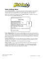
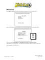
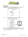
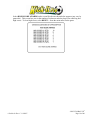
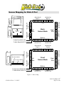
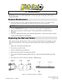
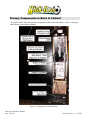
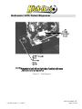
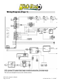
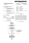
1
Kick-It Pro
Operator's Manual
612-001-00 Rev. C
¾ Read this manual before use.
¾ Keep this manual with the machine at all times.
www.globalvr.com
http://service.globalvr.com
[email protected]
[email protected]
Phone: 408.597.3435
Fax: 408.597.3437
© 2007 Global VR, Inc. All Rights Reserved. GLOBAL VR and the GLOBAL VR logo are registered trademark of Global VR, Inc. All other trademarks are the properties of their respective owners.
Table of Contents
1. Introduction...........................................................3
Warnings, Cautions, and Notes..........................3
FCC Notice ........................................................4
2. Gameplay and Description....................................4
3. Initial Setup ...........................................................5
Casters & Supports ............................................5
Ramp & Carpet ..................................................5
Check Sensors and Settings ...............................6
4. Operator Menu ......................................................7
Operator Menu Flow Chart ................................8
Machine Menu ...................................................9
Game Setup.....................................................9
Master Volume Levels..................................10
Statistics Menu .............................................11
Sensor Check ................................................12
Machine ID Menu.........................................13
Reset Menu ...................................................13
Games Menus...................................................14
Game Setup Menu ........................................15
Game Settings Menu.....................................16
Skill Levels ...................................................17
Redemption...................................................18
Statistics........................................................20
5. Troubleshooting ..................................................21
Kick-It Pro Will Not Start................................21
I Am Not Getting a Good Picture ....................21
I Am Not Getting Good Sound ........................21
I Keep Getting the Check Sensor
Message......................................................22
Advanced Troubleshooting.............................. 22
Sensor Mapping for Kick-It Pro! ..................... 23
My Game Crashes or Freezes
Unexpectedly ............................................. 24
Tickets are not Dispensing............................... 24
6. Maintenance........................................................ 25
Routine Maintenance ....................................... 25
Replacing the Ball and Tether ......................... 25
BIOS (CMOS) Settings ................................... 26
7. Replacement Parts............................................... 27
8. Illustrations ......................................................... 29
Cabinet Specifications ..................................... 29
Computer Connections .................................... 30
The Main Board............................................... 31
Primary Components in Back of
Cabinet....................................................... 32
Main Board, Ticket Dispenser, and
Amplifier.................................................... 33
Power, Service Panel, and Monitor
Control ....................................................... 34
Deltronics 1275 Ticket Dispenser.................... 35
Wiring Diagram (Page 1)................................. 36
Wiring Diagram (Page 2)................................. 37
Harness Diagram ............................................. 38
9. Warranty, Returns, and Service........................... 39
Warranty Service ............................................. 39
Limited Warranty............................................. 39
Technical Support..................................................... 3
Table of Figures
Figure 1.
Figure 2.
Figure 3.
Figure 4.
Figure 5.
Figure 6.
Figure 7.
Installing the Ramp................................ 5
Key Operator Menu Screens.................. 8
Sensor Map .......................................... 23
Connecting Tether to Cabinet .............. 25
Game Cabinet Overview...................... 29
Computer Connections ........................ 30
Main Board Connectors ....................... 31
Figure 8. Components in Cabinet Rear ................32
Figure 9. Main Board, Ticket Dispenser, and
Amplifier.........................................................33
Figure 10. Power Distribution Components.........34
Figure 11. Service Panel and Monitor Remote
Control ............................................................34
Figure 12. Ticket Dispenser .................................35
© 2007 Global VR, Inc. All Rights Reserved. No part of this publication may be reproduced in any form without
the written permission of Global VR, Inc. GLOBAL VR and the GLOBAL VR logo are registered trademarks of
Global VR, Inc. All other trademarks are the properties of their respective owners.
Every effort has been made to ensure that the information contained in this manual is accurate.
GLOBAL VR reserves the right to make alterations and improvements without prior notice.
Kick-It Pro Operator's Manual
Page 2 of 40
612-001-00 Rev. C 1/8/2007
1. Introduction
Warnings, Cautions, and Notes
The following conventions are used for Warnings and Cautions throughout the manual, and it is
essential that they be followed for safety reasons:
WARNING: Safety Precautions that must be taken to avoid a potential risk of
injury.
CAUTION: Precautions that must be taken to avoid damage to equipment.
The following Warnings and Cautions should be heeded when operating Kick-It Pro:
WARNING:
Players should not play after drinking alcohol.
Players should wear suitable shoes when playing.
Players should kick the ball only when it is in the correct position, as
indicated on the screen.
Players should be warned that Kick-It Pro is a contact game.
Players should be informed that they play at their own risk.
Switch off and disconnect the electrical power supply before opening
doors or panels, or working on the machine.
To prevent electrical shock, the game must be connected to a
grounded electrical outlet.
CAUTION:
Maintenance and repair operations should be carried out only by suitably
skilled and qualified persons.
To maintain the safety of the machine, and the warranty, use only approved
parts. The use of other parts or non-approved modifications to the machine
could be hazardous, and might void your warranty.
Many connectors are keyed to fit only one way. Note orientation before
removal.
When touching any printed circuit boards, their component parts, or other
components of the computer, follow anti-static precautions.
Do not use a pallet jack, forklift, hand truck, or dolly to move the game
after it has been removed from its shipping crate. Severe damage to the
sensors may result. Retract the supports and use the casters to move
the game.
612-001-00 Rev. C 1/8/2007
©2007 GLOBAL VR®
Page 3 of 40
FCC Notice
This device complies with Part 15 of the FCC rules. Operation is subject to the following
conditions: (1) this device may not cause harmful interference, and (2) this device must accept
any interference received, including interference that may cause undesired operations.
Note: This equipment has been tested and found to comply with the limits for a Class A digital
device, pursuant to Part 15 of the FCC Rules. These limits are designed to provide reasonable
protection against harmful interference when the equipment is operating in a commercial
environment. This equipment uses and can radiate radio frequency energy and if not installed
and used in accordance with the instruction manual may cause harmful interference to radio
communications. Operation of this equipment in a residential area is likely to cause harmful
interference in which case the user will be required to correct the interference at his own
expense.
2. Gameplay and Description
Kick-It Pro features real sports simulation in a game cabinet that will fit through a standard door.
The cabinet uses Interactive Light's patented Smart Beam™ infrared sensors to measure the
trajectory of a ball in motion. A player kicks a tethered soccer ball into the game's goal. The
measurement taken by the sensor is transmitted to a computer that controls a virtual 3-D
goalkeeper. The goalkeeper appears on screen and attempts to defend the goal.
To protect your investment, Kick-It Pro uses a sophisticated software security system. Your
machine is supplied with a device known as a Game Dongle, without which your game is not
functional. This device also sets certain operating parameters, such as the flag displayed in the
stadium, the unit of measure used to display ball velocity, and the language used in operator and
game screens.
Players select a skill level from BEGINNER (in which virtually anyone can score), through
ADVANCED and PROFESSIONAL, which are progressively harder, but potentially higher
scoring.
If a player scores a goal, the next kick will be more difficult (and higher scoring). The ball is
placed either farther back or at a greater angle to the goal. If the player misses a kick after scoring
at least once, the next kick will be easier and lower scoring. Points are awarded based on the
difficulty of the kick and the goalie's skill level; therefore, a kick from the same position is worth
more in PROFESSIONAL than in the lower skill levels.
If a player wants to try for a higher score, the player may press the BOOST button to increase
difficulty and points. This is a particularly good feature during a 2-player game, since it provides
a chance for the player with a lower score to catch up.
Bonus kicks are earned by scoring consecutive goals, goals during bonus play, goals at last kick,
and by reaching minimum difficulty levels.
Kick-It Pro Operator's Manual
Page 4 of 40
612-001-00 Rev. C 1/8/2007
3. Initial Setup
WARNING: Kick-It Pro is front-heavy and top-heavy!
When moving the cabinet, always support the front.
Casters & Supports
The game is shipped with supports withdrawn to allow the casters to roll. The supports are
located next to each caster on the bottom of the machine. Make sure they are fully withdrawn
before rolling the machine. When you have rolled the game to its proposed location, lower the
ramp and then lower the supports. You will need either an adjustable wrench or a suitable openend wrench. Lower the supports until they take the weight of the game, and the casters are
approximately ¼" (6mm) above the ground.
CAUTION:
Adjust the supports so that the front edge of the ramp is flat on the
ground and the game is level side-to-side.
Ramp & Carpet
To install the ramp, align the tabs on the upper edge of the ramp with the slots in the front of the
cabinet base. Lift the ramp up and insert the tabs into the slots. Lower the ramp to lock the tabs
in place, as shown below.
1. Lift ramp up.
2. Insert tabs in slots.
3. Lower ramp.
Tabs will lock in slots.
Note: Always make sure the
carpet is securely mounted to the
ramp. A loose carpet can be
dangerous.
Figure 1. Installing the Ramp
612-001-00 Rev. C 1/8/2007
©2007 GLOBAL VR®
Page 5 of 40
Check Sensors and Settings
1. Press the Operator button to open the Operator Menu.
2. Run the Sensor Test as described under Sensor Check on page 12.
3. Use the Operator Menu to set up your game. The following settings are some that you may
want to change:
•
VOLUME LEVELS (submenu of MACHINE/GAME SETUP menu)
•
REDEMPTION ON or OFF (in the MACHINE/GAME SETUP menu)
•
GAME PRICES (in SETUP in the GAMES menu for each game title.)
•
BALL SPEED DISPLAY (under SETUP in the GAMES menu for each game title.)
•
BALL SPEED UNIT OF MEASURE (under SETUP in the GAMES menu for each game
title)
4. Make sure your game is set up for your local voltage! Your game leaves the factory set for
either 110 VAC or 220 VAC. The Computer and the Power Supply have switches to select
the voltage. Plug the game in. A dedicated circuit is strongly recommended. If your voltage
is subject to fluctuation, installation of a surge protector or line conditioner is advisable.
5. Turn the game on, using the "ON/OFF' switch at the rear. Kick-It Pro will start in about two
minutes. If it does not, see Troubleshooting on page 21.
You are now Ready to Play
Kick-It Pro Operator's Manual
Page 6 of 40
612-001-00 Rev. C 1/8/2007
4. Operator Menu
You can access all game settings and statistics through the Operator Menu. Such settings as
game prices, volume levels, game difficulty, and redemption payouts can be adjusted to suit your
requirements.
!
In the sections that follow, this symbol
appears next to the screens with the settings
you are most likely to want to change!
Note: Some OPERATOR MENU screens display settings that are set by the dongle and cannot
be changed. They are displayed for your information only.
To access the Operator Menu, open the coin door. Inside the coin door is a panel with two
pushbuttons. One button inserts CREDITS, the other opens the OPERATOR MENU.
Press the OPERATOR (PROGRAM) button and the following screen will be displayed:
How to Navigate
To navigate in all Operator Menu screens, use the 1-Player button to go up, the 2-Player
button to go down, and the SELECT button to select a field to change. The selected field will
blink. Use the 1-Player and 2-Player buttons to make a change to the selected setting, and then
press SELECT again to save your change. Now use 1-Player or 2-Player to move to the next
field. When you are finished making changes, highlight EXIT and press the SELECT button to
return to the previous menu. You can also press the OPERATOR (PROGRAM) button from
any menu to save your changes and return to the game.
612-001-00 Rev. C 1/8/2007
©2007 GLOBAL VR®
Page 7 of 40
Operator Menu Flow Chart
Figure 2. Key Operator Menu Screens
Kick-It Pro Operator's Manual
Page 8 of 40
612-001-00 Rev. C 1/8/2007
Machine Menu
The MACHINE menu gives you access to submenus with settings and statistics that apply to all
games on the cabinet.
Game Setup
Select GAME SETUP… and the screen shown below appears. Settings in this menu apply to
all games. Use the GAMES menu to access SETUP screens for individual games, where you
can adjust game-specific settings (See page 15).
VOLUME LEVELS… is described in detail on the next page.
REDEMPTION turns ticket redemption ON or OFF.
MESSAGES… lets you set TICKETS STATUS ENABLED to ON or OFF. When ON, an
OUT OF TICKETS message is displayed onscreen when you need to replenish your supply.
DEVELOPER… is not fully available without factory authorization. It contains diagnostic
screens. You should only access it in case of problems with your game.
612-001-00 Rev. C 1/8/2007
©2007 GLOBAL VR®
Page 9 of 40
Master Volume Levels
Select VOLUME LEVELS… from the GAME SETUP menu to change Game Volume and
Attract Mode Volume, and to set the speaker balance. You can check the volume you have
selected by choosing the TEST options in the menu.
!
CAUTION:
Additional control of volume is possible by adjusting the gain of the audio
amplifier. Be careful not to over adjust the trim level of the amp, as
sound distortion or speaker damage may occur. We recommend that
you make most of your volume changes in the Operator Menus, and set
the amplifier trim level as LOW as possible.
Kick-It Pro Operator's Manual
Page 10 of 40
612-001-00 Rev. C 1/8/2007
Statistics Menu
Select STATISTICS… and the screen shown below appears. This menu lets you access
detailed statistics about your games and players. To clear statistics from the TOTALS
SCREEN, highlight CLEAR STATISTICS and press the SELECT button.
Note: Detailed statistics for individual game titles are available from the GAMES menus.
The TOTALS and BOOK KEEPING screens both display the same information, except that
BOOK KEEPING displays statistics for the lifetime of the game, while TOTALS displays
statistics for a period of time, and can be cleared.
Select AVERAGE PER GAME… for additional gameplay statistics.
To clear the statistics in TOTALS, select CLEAR STATISTICS from the STATISTICS
menu.
Note: ADVERTISEMENTS… is not supported on this cabinet.
612-001-00 Rev. C 1/8/2007
©2007 GLOBAL VR®
Page 11 of 40
Sensor Check
We recommend you run the sensor test, described below, immediately after you set up the game,
and once a month thereafter.
The game tests the sensors automatically during ATTRACT MODE and after the Game Over
slide during game play. If the test discovers a problem with the sensors, it flashes a large
CHECK SENSOR message on screen. If you see this message, run the manual sensor test from
this menu.
Select RUN TEST… from the SENSOR CHECK menu and the screen below appears.
Select RUN SENSOR TEST! to start the test. If your sensors are faulty, you will see a series of
numbers after FRONT or REAR, or both. Write these numbers down, and give them to your
technical representative, along with the information from the GAME ID screen. See page 22 for
more information. BALL ALARM warns if the ball is lying in the sensor area when you start
the test. When the ball is removed, the warning message disappears.
Kick-It Pro Operator's Manual
Page 12 of 40
612-001-00 Rev. C 1/8/2007
Machine ID Menu
The information on the MACHINE ID screen is useful for troubleshooting. If you need to call
Technical Support for help with your game, the representative will need to know what software
and firmware versions you are running.
CONFIGURATION… displays additional, detailed information on the software version and
platform, hardware installed in the computer, and directories used by the computer.
Select CURRENT DATE AND TIME… if you need to change the date and time set in the
game.
STARTUP DATE AND TIME… shows you when the game first went online.
Reset Menu
Select RESET… to revert to factory settings, erase credits, or reboot the game.
Select RESTART GAME… for a convenient way to reboot the game.
612-001-00 Rev. C 1/8/2007
©2007 GLOBAL VR®
Page 13 of 40
Games Menus
The GAMES menu displays a list of the games on the cabinet. Select a game and a screen like
the one below appears.
Use the GAMES menus to access game-specific settings and check game-specific statistics for
each game title on your cabinet,
GAME SETUP… gives you access to all settings for the game title (see page 15).
STATISTICS… lets you view or clear statistics for the game title (see page 20).
GAME ID… displays information about the game software, and lets you turn the game title ON
or OFF or set the game order.
RESET… lets you reset the game to factory settings, and clear high scores or credits.
Kick-It Pro Operator's Manual
Page 14 of 40
612-001-00 Rev. C 1/8/2007
Game Setup Menu
The GAME SETUP menu for each game gives you access to game and redemption settings for
the individual game title. Options available will vary by game title.
GAME SETTINGS… This menu gives you access to such settings as pricing, skill, and ball
speed measurement for the individual game (see page 16).
REDEMPTION… This menu lets you set up the redemption payout for the game (see page 18).
DEVELOPER… This menu provides special diagnostic information.
SAVE SETTINGS… This feature is not available on Kick-It Pro.
612-001-00 Rev. C 1/8/2007
©2007 GLOBAL VR®
Page 15 of 40
Game Settings Menu
Select GAME SETTINGS… to set pricing, check the dominant flag displayed in the stadium,
adjust the way the ball speed is displayed, select which game starts if the player makes no
selection, and set the overall difficulty level. Specific settings will vary by game title.
Note: In the example below, pricing is set in the SKILL LEVELS… submenu. Some game
titles list pricing in the GAME SETTINGS menu.
BALL SPEED DISPLAY has two options. REAL SPEED is the actual speed measured by the
sensors. VIRTUAL applies a factor that increases the displayed speed, particularly in the first two
skill levels. Serious players usually prefer to see the actual speed. Younger or less experienced
players usually enjoy the seeing the inflated value given by the VIRTUAL setting. Neither choice
affects actual game play.
INITIAL SENTRY FLAG is set by the dongle and cannot be changed. This is the dominant
flag displayed in the stadium, as well as the first flag displayed at the New High Score screen.
SPEED UNIT OF MEASURE is set by the dongle but may be changed.
SKILL LEVELS… lets you set pricing and kicks per game for each skill level (see page 17).
GAME OVERALL DIFFICULTY affects all skill levels by changing the velocity of the
kicked ball and the goalie's skill. Check STATISTICS, especially the AVERAGE PER
GAME, to help you decide when this might need to be changed.
Kick-It Pro Operator's Manual
Page 16 of 40
612-001-00 Rev. C 1/8/2007
Skill Levels
Select SKILL LEVELS... and the following screen appears (will vary by game title):
Select a skill level, and a screen like the one shown below appears (will vary by game title):
!
You may set the GAME PRICE and NUMBER OF KICKS and BONUS KICKS
independently for each skill level. To change the overall pricing structure, you must change the
price separately for all skill levels.
612-001-00 Rev. C 1/8/2007
©2007 GLOBAL VR®
Page 17 of 40
Redemption
Select REDEMPTION to set the ticket redemption payout levels. These settings apply only if
REDEMPTION is set to ON in the MACHINE/GAME SETUP menu (see page 9).
Select a skill level from the REDEMPTION menu, and a screen like following appears:
!
With the settings displayed above, each 500 points earns 1 ticket, each 3 goals earns 1 ticket,
each 2 goals in a row scores 1 ticket, and earning 2 bonus kicks earns 1 ticket. Similar settings
are used for ADVANCED, PROFESSIONAL, and BEGINNER. You can configure the
settings separately for each skill level.
Kick-It Pro Operator's Manual
Page 18 of 40
612-001-00 Rev. C 1/8/2007
Select HIGH SCORE AWARDS, and a screen like the one shown below appears (may vary by
game title). This screen lets you set the number of tickets awarded to players for achieving new
high scores. To clear high scores, select RESET… from the main menu for the game.
612-001-00 Rev. C 1/8/2007
©2007 GLOBAL VR®
Page 19 of 40
Statistics
Select STATISTICS from a game menu, and a screen like the one shown below on the left
appears. This menu lets you access detailed statistics about the game and players. Select a skill
level to view statistics for that skill level only.
Select TOTALS or BOOKKEEPING, and a screen like the one below on the right appears.
This screen gives you access to statistics that combine all skill levels. You can clear the statistics
from TOTALS, but not from BOOKKEEPING.
Select STATISTICS from the TOTALS or BOOKKEEPING screen to view the statistics. The
AVERAGE PER GAME menu is useful for determining if the game is too easy or too hard for
your players.
Kick-It Pro Operator's Manual
Page 20 of 40
612-001-00 Rev. C 1/8/2007
5. Troubleshooting
Kick-It Pro Will Not Start
Are any fans or lights on?
NO: Check the power cord, wall plug, and the ON/OFF switch on the back of the cabinet.
YES: Check the computer power cord and ON/OFF switch.
Remove any disks from Computer.
Make sure that the Computer and the Power Supply are set for your local voltage.
Check the Game Dongle on the computer to be sure it is firmly seated.
Verify Software Version Number and Dongle ID Number with your distributor.
I Am Not Getting a Good Picture
Make sure the monitor is plugged in.
Check the cable from the computer to the VGA monitor. Try a cable known to be good.
When you reboot, keep the machine OFF for at least 30 seconds before turning it back on.
If the picture doesn't fit the screen properly, it can be easily adjusted using the monitor remote
control board (see Figure 11 on page 34).
I Am Not Getting Good Sound
Check the audio cable connection to the computer and the amplifier.
Check the power cord to the amplifier.
Check the speaker connections.
In the Operator Menu, check the MACHINE/GAME SETUP/VOLUME LEVELS menu to
make sure the audio volume is high enough.
Check the trim level on the amp. If set too high, it can cause distortion and possible speaker
damage. We recommend the trim level be set low.
612-001-00 Rev. C 1/8/2007
©2007 GLOBAL VR®
Page 21 of 40
I Keep Getting the Check Sensor Message
Verify that the +5V DC output of the power supply is putting out 5.5 V with no load.
Remove any visible debris from the sensor area. Wipe the plastic sensor covers with a damp
cotton cloth. If the message does not go out, check the cables from the sensors to the main
board, and the main board to the computer.
In the Operator Menu, select MACHINE/DIAGNOSTICS and run the SENSOR CHECK.
Note any numbers that are displayed on the RUN TEST screen after running the check. Refer to
the Sensor Map on page 23, and physically inspect the LEDs that correspond to the numbers
displayed. Also inspect the Lexan in front of these LEDs for visible scratches that might cause
the bad sensor reading.
If a series of ten or twelve sequential numbers appears in SENSOR CHECK, this indicates that
a sensor cable to the Main Board is either loose or disconnected, or connected to the wrong port.
Connectors and ports are labeled. Check them to make sure they connected correctly.
Check the sensor cables to the Main Board, and from the Main Board to the computer.
It is also possible that the main board has shorted. Look for physical damage, and feel the
connectors to see if they are warm.
Note: The Main Board is accessible through the back panel. It is located above the computer on
the right side wall (see Figure 9 on page 33).
If a series of five to seven numbers is displayed, this indicates a bad sensor panel, or a loose
connection between panels. Refer to the sensor map on page 23 to determine which panel you
should check
Advanced Troubleshooting
If your game crashes, it will help Tech Support immensely to how exactly what error message
the computer is displaying. You can view error messages by entering the MACHINE/GAME
SETUP/DEVELOPER menu and choosing the DEBUG INFO screen.
If your game will not boot at all, you can view error messages on the DOS screen. To view the
DOS screen, connect the video cable from the monitor to the VGA port on the computer
motherboard (see Figure 6 on page 30 for computer connections). Write the error messages
down and call Technical Support.
Kick-It Pro Operator's Manual
Page 22 of 40
612-001-00 Rev. C 1/8/2007
Sensor Mapping for Kick-It Pro!
B-40
B-42
B-43
F-26
Top
F-10
F-27
F-9
F-28
F-8
F-29
F-7
F-30
F-6
F-4
Front
Sensor Bank
Left
Side
Right
Side
F-32
F-33
F-34
F-2
F-35
F-36
Front 8
150-0017-00
F-38
F-39
F-40
F-41
F-42
F-37
F-43
F-44
F-45
F-47
F-48
F-49
F-51
F-46
Bottom
F-0
Back 5
150-0018-00
F-31
F-3
F-1
Front 5
150-0018-00
F-24
F-23
F-22
F-21
F-20
F-19
F-18
F-17
150-0015-01
Front 4
F-16
150-0015-00
Front 3
F-15
Back 7
150-0017-00
F-14
Back 8
150-0017-00
F-25
B-47
B467
B-45
B-48
B-49
B-44
B-50
B-51
B-52
B-54
B-55
B-56
B-57
B-53
Bottom
B-0
Front 6
150-0017-00
B-1
Back 6
150-0017-00
B-24
B-23
B-22
B-25
B-39
B-41
F-50
150-0015-00
Front 2
B-38
B-2
F-5
150-0016-00
Front 1
Right
Side
B-3
B-58
150-0016-00
Back 1
B-4
Back
Sensor Bank
Left
Side
F-12
To Main Board FRONT TX
B-21
B-37
B-6
F-11
To Main Board FRONT RX
B-20
B-36
B-7
To Main Board BACK TX
Front Sensor Banks
B-19
B-35
B-8
To Main Board BACK RX
Back Sensor Banks
B-34
B-9
B-5
Sensor Bank
Locations
B-33
Top
B-10
F-13
150-0015-00
Back 2
B-11
150-0015-01
Back 4
B-18
B-17
B-16
B-15
B-14
B-13
B-12
150-0015-00
Back 3
Front 7
150-0017-00
Figure 3. Sensor Map
612-001-00 Rev. C 1/8/2007
©2007 GLOBAL VR®
Page 23 of 40
My Game Crashes or Freezes Unexpectedly
•
Try to figure out exactly what happened to cause the game to crash. Try to duplicate the
circumstances that led up to the crash.
•
From the DEVELOPER screens in the Operator Menu, select DEBUG INFO and note the
error messages displayed there. The DEVELOPER screens are under MACHINE/GAME
SETUP, and the GAME SETUP menus for individual game titles.
•
Violent kicking may have jarred the computer's hard drive. Try rebooting first. If the
problem persists, you may need a new hard drive. (part 514-0003-00).
•
Check the System Computer to make sure it is firmly strapped in place.
•
See the other sections under Troubleshooting for further information.
Tickets are not Dispensing
•
Check the REDEMPTION screen in the OPERATOR MENU. Make sure ENABLED is ON.
•
Check the connections and voltages. Refer to the schematic diagram.
Kick-It Pro Operator's Manual
Page 24 of 40
612-001-00 Rev. C 1/8/2007
6. Maintenance
Kick-It Pro requires very little maintenance. To keep your game in top shape, follow these
simple instructions.
Routine Maintenance
•
Keep the Sensor area clean. Wipe up drink spills and remove debris. We suggest a wipe
down with a damp rag periodically, to make sure the sensors are not obscured.
CAUTION: Do not use abrasive cleaners! Use only cotton cloth!
•
Run the SENSOR TEST monthly. See Sensor Check on page 12 for instructions.
•
Make sure your carpet is securely in place. Order replacements as needed from your
distributor.
•
Check the condition of the ball, swivel and tether periodically. Always have a spare on hand.
Contact your distributor for replacements.
Replacing the Ball and Tether
This swivel is an Eye and Jaw Swivel. The eye is the closed side of the swivel and the jaw is the
side with a removable pin. The pin can be removed using a pair of pliers to grasp and turn the
head.
1. Remove the V-Bolt from the rubber mat.
2. Place the Eye into the U-Bolt.
3. Put the U-bolt back on the rubber mat.
4. Remove the pin from the Jaw using a pair of pliers.
5. Place loop of the tether into the opening of the Jaw. Place pin back through the loop of the
tether.
6. Put a drop of Loc-Tite® on the screw threads. Tighten the pin.
Figure 4. Connecting Tether to Cabinet
612-001-00 Rev. C 1/8/2007
©2007 GLOBAL VR®
Page 25 of 40
BIOS (CMOS) Settings
Note: These settings are for Cabinets Manufactured in 2006 and later.
Follow the steps below to check or change the BIOS settings for the Kick-It Pro computer.
Change only the settings described in this section. The other settings should not affect the game.
1. Power OFF the Kick-It Pro cabinet and connect a PS/2 keyboard to the computer.
2. Power ON cabinet and press the Delete key on the keyboard as the computer boots. The
CMOS Setup Utility screen will appear, as shown below.
3. Use the arrow keys to select a settings menu from the left side of the screen, and press the
Enter key to enter the menu.
4. Use the arrow keys to change the settings shown in the tables below, as necessary. When
finished, press the F10 key to save your changes.
A: Drive
B: Drive
Halt ON
Standard CMOS Features
None
None
NO ERRORS
Advance BIOS Features
First Boot Device
CD-ROM
Second Boot Device
HDD-0
Third Boot Device
Disabled
Boot Other Device
Enabled
Integrated Peripherals
Onboard FDC Controller
Disabled
Onboard Serial Port 1
AUTO
Onboard Serial Port 2
Disabled
Parallel Port Mode
EPP
PWRON After PWR-FAIL
Game Port Address
Midi Port Address
ON
Disabled
Disabled
PNP / PCI Configuration
Resources Controlled by
Auto ESCD
Advance Chipset Features
Video BIOS Cacheable
Enabled
Kick-It Pro Operator's Manual
Page 26 of 40
612-001-00 Rev. C 1/8/2007
7. Replacement Parts
Spare parts for this machine can be obtained from our Customer Service Department, (408) 597-3435.
When ordering parts, please specify the following information:
•
•
•
Name of machine and Serial Number (see the label located on back of machine)
Name and Part Number of the Part
Any additional information that may help to specify that part e.g. voltage or coinage type.
Part Type
Ball & Tether
Parts
Qty
1
1
1
1
1
1
1
1
1
1
1
3
1
1
1
1
1
1
1
1
1
1
1
1
1
2
Part No.
49-5223-00
480-0004-00
480-0005-00
49-5223-10
586-0002-00
586-0001-00
586-0001-01
586-0001-02
586-0001-03
495-0009-00
400-0033-00
400-0036-00
400-0028-00
DFI-P2XLXE
VOODOO2
H4-MEMOHASP
415-0016-00
415-0015-00
415-0019-00
415-0003-00
415-0001-00
415-0002-00
415-0018-00
415-0004-00
AW-KICKIT-01
1123LBT
Audio
Components
Part Description
#4 Soccer Ball
Eye-Jaw Swivel for Ball
¼" U-Bolt for Ball
Soccer Ball tether
Boost Button
1-Player Button
2-Player Button
Select Button
Start Button
Carpet in front of the game, covering the ramp
Ramp
Goal Mouth Back Wall Foam Pads
Rubber Mat – Hanging in back of goal area
System Computer, DFI
VOODOO 2 Video Card inside computer
Game Dongle (Exchange Only)
Ticket / DBV Door
Coin Door
Floor Piece (Warning Sign)
Main Cabinet Side
Control Panel Overlay
Cabinet Side, Upper
Game Logo Marquee
Monitor Outline with "Real Sports Simulation"
Decals, Ten Piece Set (Primarily Green Artwork Version)
Cabinet Fan, 115 VAC, 11 Watts, 120sqmm x 38mm (Above
monitor and at top side of cabinet.)
Power Plate Assembly
DC Power Supply, 5V/12V 115 W
110 VAC Florescent Light Fixture, 18", for marquee
Coin Door, Over/Under, Happ w/ Harness
Door w/ Dispenser, Bracket, Switches, and Harness
Deltronics DL 1275 Ticket Dispenser Mechanism
Ticket Dispenser Bin
Door, Ticket, w/bin, no-dispenser
Vertical Rubber Safety Bar (Sides of outer goal area.)
Horizontal Rubber Safety Bar (Above outer goal area.)
Audio Amplifier
Audio speakers, left and right
1
1
1
1
1
1
1
1
2
1
1
1
Document
Operator's Manual
1
45007-00
44-1100-01
49-1001-00
40-6000-04
530-0012-00
530-0013-00
530-0014-00
40-0543-00
497-500-306W
497-500-307W
518-0005-00
5.25 SPEAKER
PAIR
612-0001-00
Control Panel
Buttons
Misc. Parts
Computer
Dongle
Decals
(Primarily Yellow
Artwork Version)
Decal Set
Electric
Components
Coin and Ticket
Components
Safety Bars
612-001-00 Rev. C 1/8/2007
©2007 GLOBAL VR®
Page 27 of 40
Part Type
PCB
Sensor PCBs
Sensor Covers
Sensor Cover
Retainers
Lexan Covers
Monitor
Cables
Part Description
Main Board
Front 4 & Back 4 Receiver PCB
Front 2, 3 and Back 2, 3 Receiver PCB
Front 1 & Back 1 Receiver PCB
Front 6, 7, 8 & Back 6, 7, 8 Transmitter PCB
Front 5 & Back 5 Transmitter PCB
Goal Mouth, Plexiglas – Right Side
Goal Mouth, Plexiglas – Left Side
Goal Mouth, Plexiglas – Bottom
Goal Mouth, Lexan – Top
Sensor Cover, Metal Sensor Bracket - Short
Sensor Cover, Metal Sensor Bracket - Long
For junction of side, top, and bottom sensor covers
For the rear of top, bottom, and side sensor covers
Lexan Protective Cover for Monitor
Lexan Protective Cover for Marquee
VGA Monitor, 33" Digital Clear (Wells Gardner)
Qty
1
2
4
2
6
2
1
1
1
1
1
1
4
4
1
1
1
DC Power Supply Out
Main PCB 9 pin Out
Control Panel Switches
Control Panel Lamps
Main PCB 15 Pin Out
15 Pin Extension
Sensor Ribbon Cable #1
Sensor Ribbon Cable #2
Sensor Ribbon Cable #3
Main AC Harness to Cabinet Components
AC Out from EMI Filter
Fluorescent Lamp Power
Duplex
Speaker Wires
Service Panel Harness
RS232 Cable
Card Reader AC
Ticket Dispenser Harness
Power Plate to EMI Filter
Power Cord, 6'
Power Cord to Florescent Light
Ticket LED & Control Extension
CBL,NFS 110VAC TO +24VDC SUPPLY REV C
Fan Cable, 90° Angle, T-Style Plug and Cord, 72"
1/8" Jack to RCA Cable, 6' (Computer to Audio Amplifier)
1
1
1
1
1
1
2
1
1
1
1
1
1
1
1
1
1
1
1
1
1
1
1
2
1
Kick-It Pro Operator's Manual
Page 28 of 40
Part No.
150-0010-00
150-0015-00
150-0015-01
150-0016-00
150-0017-00
150-0018-00
400-0029-00
400-0030-00
400-0031-00
400-0032-00
400-0042-00
400-0043-00
400-0037-00
400-0038-00
400-0039-00
400-0040-00
WGM3392UOTS07C
ILKP-101-00
ILKP-102-00
ILKP-103-00
ILKP-104-00
ILKP-105-00
ILKP-106-00
ILKP-107-00
ILSL-108-00
ILKP-109-00
ILKP-111-00
ILKP-112-00
ILKP-113-00
ILKP-114-00
ILKP-115-00
ILKP-116-00
ILKP-117-00
ILKP-118-00
ILKP-119-00
ILSL-110-00
80-0213-00
GLO-PWRCORD
KIPRO-131-00
115-0008-01
115-0034-01
04-007-1003
612-001-00 Rev. C 1/8/2007
8. Illustrations
Cabinet Specifications
Figure 5. Game Cabinet Overview
Cabinet Dimensions:
Height: 78½" (200 cm)
Width: 55" (140 cm)
Depth: 31" (80 cm) + 5' x 5' (150 cm x 150 cm) turf playing area in front of
cabinet, for a Total Depth of 91" (230 cm)
612-001-00 Rev. C 1/8/2007
©2007 GLOBAL VR®
Page 29 of 40
Computer Connections
Figure 6. Computer Connections
Kick-It Pro Operator's Manual
Page 30 of 40
612-001-00 Rev. C 1/8/2007
The Main Board
Figure 7. Main Board Connectors
612-001-00 Rev. C 1/8/2007
©2007 GLOBAL VR®
Page 31 of 40
Primary Components in Back of Cabinet
The picture below shows the primary components at the back of the cabinet. Refer to the pages
that follow for more detailed photos.
Figure 8. Components in Cabinet Rear
Kick-It Pro Operator's Manual
Page 32 of 40
612-001-00 Rev. C 1/8/2007
Main Board, Ticket Dispenser, and Amplifier
Figure 9. Main Board, Ticket Dispenser, and Amplifier
612-001-00 Rev. C 1/8/2007
©2007 GLOBAL VR®
Page 33 of 40
Power, Service Panel, and Monitor Control
The view below shows the area below the computer shelf.
Figure 10. Power Distribution Components
Open the coin door to access the service panel and monitor remote control board, shown below.
Figure 11. Service Panel and Monitor Remote Control
Kick-It Pro Operator's Manual
Page 34 of 40
612-001-00 Rev. C 1/8/2007
Deltronics 1275 Ticket Dispenser
Figure 12. Ticket Dispenser
612-001-00 Rev. C 1/8/2007
©2007 GLOBAL VR®
Page 35 of 40
Wiring Diagram (Page 1)
Kick-It Pro Operator's Manual
Page 36 of 40
612-001-00 Rev. C 1/8/2007
Wiring Diagram (Page 2)
612-001-00 Rev. C 1/8/2007
©2007 GLOBAL VR®
Page 37 of 40
Harness Diagram
4-Pin
Molex
To Ticket Dispenser
To Control
Panel
Buttons
Main Board
Switch In
(9-Pin Molex)
Coin In
(15-Pin Molex)
Lamp Out
(12-Pin Molex)
J5
6-Pin
Molex
To Coin
Switch &
Lamp
3-Pin
Molex
DC Power Out
(Spare)
6-Pin
Molex
ILKP-103-00
P2
ILKP-102-00
6-Pin
Molex
J3
P4
Sensor Connector
(DB-9)
To
Computer
J7
Back TX
Front RX
Back RX
To Control
Panel Button
Lamps
ILKP-104-00
2-Pin
Molex
J6
BLK
VIO
ILKP-106-00
J4
P3
Front TX
15-Pin
Molex
9-Pin
Molex
ILKP-105-00
To Coin
Meter
3-Pin
Molex
ILKP-116-00
Bottom Front
Sensor Bank
ILKP-109-00
Right Front
Sensor Bank
ILKP-107-00
Bottom Back
Sensor Bank
ILKP-109-00
Right Back
Sensor Bank
ILKP-108-00
Left Front
Sensor Bank
ILKP-109-00
Top Front
Sensor Bank
ILKP-108-00
Left Back
Sensor Bank
ILKP-109-00
Top Back
Sensor Bank
Power
(6-Pin Molex)
ILKP-101-00
To Ticket Counter
To Ticket Switch
RED
WHT
To Ticket LED
Sensor Bank
Assemblies
Speaker
Jumper
Harness
7A
Fuse
RED +12 V DC Power
2-Pin
Molex
To Operator and
Instant Credit Buttons
ILKP-107-00
3-Pin
Molex
ILKP-119-00
ORANGE +12 V TURN ON/PWR. ANT.
ILKP-115-00 To Cabinet
Speakers
Audio
Amp
Audio In from
Computer Audio Out
BLACK CHASSIS GND
Power Distribution
BLK GND
To DC Power OUT
Terminals on
DC Power Supply
RED +5 VDC
YEL +12 VDC
GRN-YEL
To AC Power IN
Terminals on
DC Power Supply
BLU
BRN
Main AC In at
Power Plate
To Cabinet Fan
Above Computer
BLU
15-Pin
Molex
ILKP-111-00
BRN
GRN-YEL
GND
ILKP-112-00
GRN-YEL
Filter
BLU
BLU
BRN
EMI
BRN
3-Pin
Molex
GRN-YEL
ILSL-110-00
To Cabinet Fan
Above Monitor
To
Marquee
Florescent
Light
3-Pin
Molex
Note: This drawing reflects cabinets manufactered in 2006 and later.
Kick-It Pro Operator's Manual
Page 38 of 40
612-001-00 Rev. C 1/8/2007
9. Warranty, Returns, and Service
Warranty Service
If at some point you require warranty service, contact your authorized GLOBAL VR® distributor.
Limited Warranty
GLOBAL VR® warrants that its computer circuit boards, hard drives, power supplies, monitors, displays, controls, sensors, and
mechanical structures are free from defects in materials and workmanship under normal use and service for a period of ninety (90)
days from the date of shipment.
All software and accompanying documentation furnished with, or as part of the Product, is supplied “AS IS” with no warranty of any
kind except where expressly provided otherwise in any documentation or license agreement furnished with the Product.
During the warranty period, GLOBAL VR® will, at no charge, repair the Product, provided:
- Purchaser believes that the Product is defective in material or workmanship and promptly notifies GLOBAL VR® in writing with
an explanation of the claim;
- All claims for warranty service are made within the warranty period;
- Products are returned adequately packed and freight prepaid to GLOBAL VR®’s designated service center;
- GLOBAL VR®’s inspection or test of the Product verifies to GLOBAL VR®’s satisfaction that the alleged defect(s) existed and
were not caused by accident, misuse, neglect, unauthorized or attempted repair or testing, unauthorized modification, incorrect
installation, vandalism, failure to follow the maintenance schedule or procedures; or operation in out-of-specification
environmental conditions.
GLOBAL VR® will return the repaired Product freight prepaid to the Purchaser. All freight costs associated with replacement of
warranty parts after expiration of the original warranty period are the responsibility of the Purchaser. GLOBAL VR® is not obligated
to provide the Purchaser with a substitute unit or on-site service during the warranty period or at any time. If after investigation
GLOBAL VR® determines that the reported problem was not covered by the warranty, Purchaser shall pay GLOBAL VR® for the
cost of investigating the problem at its then prevailing per incident billing rate. No repair or replacement of any Product or part
therein shall extend the warranty period as to the entire Product. The warranty on the repaired part only shall be in effect for a
period of ninety (90) days following the repair or replacement of that part or the remaining period of the Product parts warranty,
whichever is greater.
Purchaser’s exclusive remedy and GLOBAL VR®’s sole obligation is to supply or pay for all labor necessary to repair any Product
found to be defective within the warranty period and to supply, at no extra charge, new or rebuilt replacements for defective parts. If
repair or replacement fails to remedy the defect, then, and only in such event, shall GLOBAL VR® refund to Purchaser the purchase
price for said Product. Purchaser’s failure to make a claim as provided above or continued use of the Product shall constitute an
unqualified acceptance of said Product and a waiver by Purchaser of all claims thereto.
IN NO EVENT SHALL GLOBAL VR® BE LIABLE FOR LOSS OF PROFITS, LOSS OF USE, INCIDENTAL OR
CONSEQUENTIAL DAMAGES RESULTING FROM OPERATION OF THE GAME IN ANY CONDITION. GLOBAL VR®
SHALL NOT BE RESPONSIBLE FOR THE SUITABILITY, PERFORMANCE, OR SAFETY OF ANY NON- GLOBAL VR®
PART OR ANY MODIFICATION PERFORMED BY ANY PRODUCT DISTRIBUTOR UNLESS SUCH WORK IS
EXPRESSLY AUTHORIZED IN ADVANCE BY GLOBAL VR®.
THIS WARRANTY IS IN LIEU OF ALL OTHER EXPRESSED OR IMPLIED WARRANTIES, INCLUDING THE IMPLIED
WARRANTIES OF MERCHANTABILITY AND FITNESS FOR A PARTICULAR PURPOSE, AND ALL OTHER
OBLIGATIONS OR LIABILITIES ON GLOBAL VR®’S PART, EXCEPT FOR ANY EXPRESS WARRANTY SET FORTH IN
A WRITTEN CONTRACT BETWEEN GLOBAL VR® AND PURCHASER CONTAINING SPECIFIC TERMS WHICH
SUPERSEDE THE TERMS HEREIN. THIS WARRANTY DOES NOT AUTHORIZE ANY OTHER PERSON TO ASSUME
OTHER LIABILITIES, IF ANY, CONNECTED WITH THE SALE OF PRODUCTS BY GLOBAL VR®.
612-001-00 Rev. C 1/8/2007
©2007 GLOBAL VR®
Page 39 of 40
Technical Support
Service & Parts
Hours: 7:00AM–5:00PM Pacific Time, Monday–Friday
Phone: 408.597.3435
Fax: 408.597.3437
E-mail: [email protected]
Website: http://service.globalvr.com
Extended Service Hours:
Monday–Friday 5pm—Midnight
Saturday & Sunday 7:00am—Midnight Pacific Time
Free telephone, e-mail, and online support are provided for systems during the warranty period.
GLOBAL VR® Technical Support can help you troubleshoot problems and diagnose defective
parts. We can also answer questions about the operation of your game.
When you contact Technical Support, please provide the information listed below, as applicable,
to assist the Technical Support representative in solving your problem quickly. For your
convenience, space is provided to write important numbers.
•
Cabinet Serial Number:
•
Proof of Purchase information
•
Your mailing address and telephone number
•
A summary of the question or a detailed description of the problem
•
Specific error message
•
Date of latest install or upgrade
•
Any changes made to the system
•
For game-play issues, the game and number of players