1
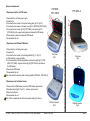
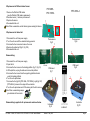
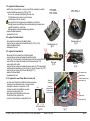
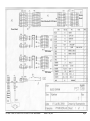
Service Manual for
Plate Shakers-Thermostats PST-60HL/PST-100HL/PST-60HL-4
Periodical maintenance
Plate Shakers-Thermostats PST-60HL/PST-100HL/PST-60HL-4 does not require periodical technical maintenance, except cleaning.
Cleaning. Standard ethanol (75%) or any other cleaning liquids can be used for cleaning and disinfecting of the device, if it does not contain any strong
organic solvents (such as acetone, toluene or benzene).
PST-60HL
PST-60HL - V.2AW, PST-100HL - V.1AW, PST-60HL-4 - V.2AW Service Manual
PST-100HL
Version 4 - May 2013
PST-60HL-4
Page 1
The following spare parts are available for Plate Shakers-Thermostats PST-60HL/PST-100HL/PST-60HL-4:
No.
Spare part
5
6
9
8
10
7
1
3
11
12
2
13
4
14
Control Board
LCD Board
Power Board
Button Board
Speed Sensor Board
Microprocessor
PCB Heater
Rubber belt
Motor
Shaking Block
Thermosensor
Power Switch
Casing (bio)
Power Socket
Marking
PST-60HL-4
PST-100HL
MASTR1
BC1602AGPLCTb
SUPPLY BIOR
BUTTON R3
SSB
PIC16F628P-20
TSP2
OVEN4
2PS1S
117x5x0.6
9904 120 16703 / DC40
PST
DS18B20
H8600VB1
H8600VB1
PST-60HL
PST-60HL-4
PST-100HL
HEBL 2,1mm
PST-60HL
PST-60HL - V.2AW, PST-100HL - V.1AW, PST-60HL-4 - V.2AW Service Manual
PST-60HL
BS-010119-S01
BS-010119-S27
BS-010119-S03
BS-010119-S04
BS-010119-S05
BS-010119-S06
BS-010119-S07
BS-010119-S08
BS-010119-S09
BS-000000-S02
BS-010119-S10
Version 4 - May 2013
Article
PST-60HL-4
BS-010128-S01
BS-000000-S01
BS-010128-S34
BS-010128-S03
BS-010128-S04
BS-010128-S05
BS-010128-S06
BS-000000-S18
BS-010128-S07
BS-010128-S08
BS-010128-S09
BS-010128-S10
BS-000000-S03
PST-100HL
BS-010142-S01
BS-010142-S18
BS-010142-S03
BS-010142-S04
BS-010142-S05
BS-010142-S06
BS-010142-S07
BS-010142-S08
BS-010142-S09
BS-000000-S02
BS-010142-S10
Page 2
Spare part replacement
1. Replacement of the Lid PCB Heater:
1. Disconnect the unit from power supply.
2. Open the lid.
3. Unscrew the four screws on the upper heating plate (fig.1/2, fig.2/2 ).
4. Unscrew the two screws on the wire cover (fig.1/3) [PST-60HL,PST-100HL].
5. Unscrew the four screws (fig.1/4) [PST-100HL] / six screws (fig.2/3)
[PST-60HL-4] on the upper heating plate and release the PCB heater.
1
6. Disconnect the cable and replace the PCB Heater.
7. Re-assemble the unit.
4
3
PST-60HL
PST-100HL
PST-60HL-4
2
2
3
1
1. Replacement of Platform PCB Heater:
1. Disconnect the unit from power supply.
2. Open the lid.
3. Unscrew the four screws on the heating platform (fig.1/1, fig.2/1).
4. Lift the platform, unplug the cable.
5. On the underside of the heating platform unscrew the eight (fig.7/1) [PST60HL, PST-100HL] / eighteen screws (fig.8/1) [PST-60HL-4] and remove
the PCB Heater.
6. Replace the PCB heater.
7. Re-assemble the unit.
Note: Use sealant to seal the sides of heating platform [PST-60HL, PST-60HL-4].
Front view
V
fig.1
Front view
fig.2
V
2. Replacement of Lid Heater Sensor:
1. Remove the Lid PCB Heater (see the Lid PCB Heater replacement).
2. Desolder sensor (fig.5/1, fig.6/1) (1. scheme) and remove it.
3. Replace the Sensor.
4. Re-assemble the unit.
Note: When re-assemble use the thermal grease sealing the Sensor.
Platform removed
V
PST-60HL - V.2AW, PST-100HL - V.1AW, PST-60HL-4 - V.2AW Service Manual
fig.3
Version 4 - May 2013
Platform removed
fig.4
V
Page 3
2. Replacement of Platform Heater Sensor:
1. Remove the Platform PCB Heater
(see the Platform PCB Heater replacement).
2. Desolder sensor (1. scheme) and remove it.
3. Replace the sensor.
4. Re-assemble the unit.
Note: When re-assemble use the thermal grease sealing the Sensor.
PST-60HL
PST-100HL
PST-60HL-4
1
1
3. Replacement of rubber belt:
1. Disconnect the unit from power supply.
2. Turn the unit over with the underside facing upwards.
3. Unscrew the four screws and remove the cover.
4. Replace the rubber belt (fig.9/1, fig.10/2).
5. Re-assemble the unit.
Thermosensor
Thermosensor
M
fig.6
fig.5
M
1
1
Disassembling:
1. Disconnect the unit from power supply.
2. Open the lid.
3. Unscrew the four screws on the heating platform (fig.1/1, fig.2/1).
4. Lift the platform, unplug the cable and remove the platform.
5. Unscrew the four screws from the supporting platform situated
under the heating platform.
6. Turn the unit upside down.
7. Unscrew the five (fig.9/2) [PST-60HL, PST-100HL] / eight (fig.10/1)
[PST-60HL-4] screws on the edges of the underside.
8. Turn the unit upside down and lift the casing with the lid to remove.
Note: When re-assembling always
glue terminals to the sockets.
Disassembling is applied to all replacements mentioned below.
PST-100HL
PST-60HL
fig.8
PCB board
M
M
fig.7
1
1
2
fig.9
Version 4 - May 2013
2
Underside
Underside
M
PST-60HL - V.2AW, PST-100HL - V.1AW, PST-60HL-4 - V.2AW Service Manual
PCB board
fig.10
M
scheme.1
Page 4
4. To replace the Casing:
PST-60HL
PST-100HL
– remove the lid PCB heater (see the Lid PCB Heater replacement);
– unscrew three (fig.11/3) [PST-60HL, PST-100HL] / four (fig.12/3)
[PST-60HL-4] screws on electronics base plate and remove it;
– replace the Casing;
– re-assemble the unit.
5. To replace Control Board:
1
4 5
2
– disconnect the terminals from the Control Board;
– unscrew the four screws on the Control Board assembly (fig.11/1, fig.12/1);
– remove Control Board;
– replace the Control Board;
– re-assemble the unit.
Note: LCD Board connected with Control Board via socket.
During installation avoid mechanical strain of LCD Board. If washers was
applied between Control and LCD Board before disassembling, then
mount them back while re-assembling.
PST-60HL-4
3
1 4
5
2
3
6. To replace LCD Board:
– disconnect the terminals from the Control Board;
Lifted casing
– unscrew the four screws on the Control Board assembly (fig.11/1, fig.12/1);
fig.11
– remove the LCD Board located under the control board;
– replace the LCD Board;
– re-assemble the unit.
Note: During installation avoid mechanical strain of LCD Board. If washers was applied
between Control and LCD Board before disassembling, then mount them back while
re-assembling.
Control and button board
M
fig.12
M
LCD contrast tuning
– after replacing the Control Board or the LCD Board, LCD display need contrast tuning;
– to tune contrast of the display, it is necessary to connect to the
circuit and switch the unit without re-assembling;
– take necessary precautions against electric shock hazard;
– connect the cables and power wires;
– plug in the power cord to the circuit and switch on the unit;
– the display lites up;
– turn the potentiometer screw (fig.11/4, fig.12/4) and tune the display contrast;
– re-assemble the unit.
PST-60HL - V.2AW, PST-100HL - V.1AW, PST-60HL-4 - V.2AW Service Manual
Version 4 - May 2013
scheme.2
Page 5
7. To replace the Microprocessor:
PST-60HL
PST-100HL
– with the help of special tool or using a small, flat tip screwdriver carefully
remove the Microprocessor (fig.11/5, fig.12/5);
Do not mix up correct side installing the new one!
The Microprocessor’s and connector’s shape
has the same notch (2. scheme).
Use special tool for microprocessor installation, do not touch
microprocessor pins with bare hands, while replacing microprocessor
use ESD-protection – wrist strap.
Microprocessor is delivered already programmed.
– replace the Microprocessor;
– re-assemble the unit.
PST-60HL-4
1
1
8. To replace the Button Board:
– disconnect the terminal from the Button Board;
– unscrew the four screws on the Button Board (fig.11/2, fig.12/2);
– replace the Button Board;
– re-assemble the unit.
Disassembled unit
fig.14
Disassembled unit
M
M
fig.13
2 1
1
9. To replace the Power Board:
– disconnect all the terminals from the Power Board;
– unscrew the two screws and release the platform heater
wires (fig.17/2) wire polarity don't matter (wires from the bunch with knot);
– unscrew the two screws and release the lid heater wires (fig.17/3)
wire polarity don't matter;
– unscrew the two screws and release the power wires (fig.17/4) wire polarity
matters while reassembling connect the red (+) wire as shown in (fig.17/4)
– unscrew the two screws on the Power Board (fig.17/1);
– replace the Power Board;
– re-assemble the unit.
9.1. To replace the newer Power Board on older unit:
2
Rear view
Rear view
fig.15
fig.16
M
M
Lid heater sensor
Speed Sensor
Platform heater sensor
(wires with knot)
Power for
lid heating
– on older units Lid heater and Platform heater sensor wire
connectors have three wire slots, on newer only two;
– to adapt the old wires to new board, cut off
Old
old wire connector and install the new wire
connector according to fig.17a;
– when looking from terminal lever side move
the left wire to the right wire slot;
– connect to the board and re-assemble the unit.
Power for
platform heating
(wires from the
bunch with knot)
New
1
4
Power input
2
Power for motor
3
123
2 13
Connector wiring
fig.17a
Power board
M
PST-60HL - V.2AW, PST-100HL - V.1AW, PST-60HL-4 - V.2AW Service Manual
M
Version 4 - May 2013
fig.17
Page 6
10. To replace the Speed Sensor Board:
– unscrew the four screws and turn over Shaking Block (fig.13/1, fig.14/1);
– disconnect the wire from the Power Board;
– unscrew the two fixing screws on the Speed Sensor holder bar (fig.18/3);
– unscrew the two fixing screws on the Speed Sensor Board (fig.18/2);
– replace the Speed Sensor Board;
– to adjust the position of the Speed Sensor Board, it is necessary to
connect to the circuit and switch the unit without re-assembling;
– take necessary precautions against electric shock hazard;
– turn the sheave and adjust the position of Speed Sensor Board till RPM
readings are displayed;
– tight up the screws (fig.18/3);
– re-assemble the unit.
PST-60HL
PST-100HL
PST-60HL-4
11. To replace the Motor:
– disconnect the motor power supply wire from the power board;
– unscrew the four screws and turn upside down the Shaking Block (fig.13/1, fig.14/1);
– remove the rubber belt;
– unscrew the four screws (fig.18/1) and remove the Motor;
– replace the Motor;
– re-assemble the unit.
1
2
3
Shaking block
fig.18
M
12. To replace the Shaking Block:
– unscrew the four screws and remove Shaking Block (fig.13/1, fig.14/1);
– remove the speed sensor board (see speed sensor board replacing);
– remove the rubber belt;
– unscrew the four screws (fig.18/1) and remove the motor;
– replace the Shaking Block;
– re-assemble the unit.
Not used
scheme.3
13. To replace the Power Switch:
– pull out the Power Switch (fig.15/2, fig.16/2);
– disconnect the wires;
– replace the Power Switch and re-assemble the unit.
14. To replace the Power Socket:
– unscrew the Power socket from the casing (fig.15/1, fig.16/1);
– solder out the power wires from the socket (3. scheme);
– replace the Power socket and re-assemble the unit.
PST-60HL - V.2AW, PST-100HL - V.1AW, PST-60HL-4 - V.2AW Service Manual
Version 4 - May 2013
Page 7
Control Board with LCD Board
Button
Board
Power Board
PCB Heater
PCB Heater
Speed
Sensor
Board
PST-60HL - V.2AW, PST-100HL - V.1AW, PST-60HL-4 - V.2AW Service Manual
Version 4 - May 2013
Page 8
Button
Board
Control Board with LCD Board
Power Board
PCB Heater
PCB Heater
Speed
Sensor
Board
PST-60HL - V.2AW, PST-100HL - V.1AW, PST-60HL-4 - V.2AW Service Manual
Version 4 - May 2013
Page 9
Button
Board
Control Board with LCD Board
Power Board
PCB Heater
PCB Heater
Speed
Sensor
Board
PST-60HL - V.2AW, PST-100HL - V.1AW, PST-60HL-4 - V.2AW Service Manual
Version 4 - May 2013
Page 10