1
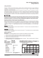
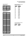
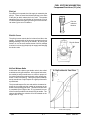
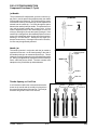
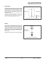
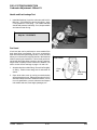
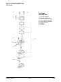
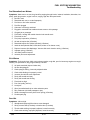
CHAPTER 4
FUEL SYSTEM/CARBURETION
Jetting Guidelines . . . . . . . . . . . . . . . . . . . . . . . . . . . .
Main Jet Selection . . . . . . . . . . . . . . . . . . . . . . . . . . . .
Fuel and Oil Tank Asm. Exploded View, 2 Cycle . .
Fuel Tank Asm. Exploded View, 4 Cycle . . . . . . . . .
Fuel Flow Diagrams . . . . . . . . . . . . . . . . . . . . . . . . . . .
Main Jet / Pilot Jet Part Numbers . . . . . . . . . . . . . . .
2 Cycle Section
Carburetor Component Function (2 Cycle) . . . . . . .
Carburetor Circuit Operation (2 Cycle) . . . . . . . . . . .
Carburetor Vent Systems (2 Cycle) . . . . . . . . . . . . .
Float Height Adjustment (2 Cycle) . . . . . . . . . . . . . .
Needle and Seat Leakage Test (2 Cycle) . . . . . . . .
Exploded View, Mikuni VM 30 / 34 SS Carburetor
4 Cycle Section
CV Carburetor System Function (4 Cycle) . . . . . . .
CV Carburetor Vent System (4 Cycle) . . . . . . . . . . .
CV Carburetor Operation . . . . . . . . . . . . . . . . . . . . . .
Exploded View, Mikuni BST 34 Carburetor . . . . . . .
Exploded View, Mikuni BST 40 Carburetor . . . . . . .
Disassembly Notes, CV Carburetor . . . . . . . . . . . . .
Cleaning, CV Carburetor . . . . . . . . . . . . . . . . . . . . . .
Inspection, CV Carburetor . . . . . . . . . . . . . . . . . . . . .
Assembly, CV Carburetor . . . . . . . . . . . . . . . . . . . . . .
Adjustment, CV Carburetor . . . . . . . . . . . . . . . . . . . .
Fuel Pump
Fuel Pump Disassembly / Inspection / Assembly .
Fuel Pump Exploded View . . . . . . . . . . . . . . . . . . . . .
Troubleshooting . . . . . . . . . . . . . . . . . . . . . . . . . . . . . .
4.1
4.1
4.2
4.3
4.4
4.5
4.6 - 4.9
4.10 - 4.15
4.16
4.16
4.16
4.17
4.18
4.18
4.19 - 4.21
4.22
4.23
4.24 - 4.25
4.26
4.27
4.28
4.29 - 4.30
4.31
4.32
4.33 - 4.34
FUEL SYSTEM/CARBURETION
Jetting Guidelines
Jetting Guidelines
Changes in altitude and temperature affect air density, which is essentially the amount of oxygen available for
combustion. In low elevations and cold temperatures, the air has more oxygen. In higher elevations and higher
temperatures, the air is less dense.
Carburetors on Polaris ATV and 6x6 vehicles are calibrated for an altitude of 0-3000 ft. (0-900 meters) and ambient temperatures between +40 and +80° F (+5° to +26° C). Carburetors must be re-calibrated if operated outside
the production temperature and/or altitude range. The main jet installed in production is not correct for all altitudes
and/or temperatures. In addition, air screw / pilot screw adjustments may be required to suit operating conditions.
CAUTION:
A main jet that is too small will cause a lean operating condition and may cause serious engine damage.
Select the correct main jet carefully for elevation and temperature according to the charts in the General/
Specifications Chapter, or in the Owner’s Safety and Maintenance Manual for each particular model.
Air Screw (2 Cycle) / Pilot Screw (4 Cycle) Adjustment
NOTE: Maximum engine efficiency and horsepower are directly related to proper carburetor and clutch settings.
The jetting charts should be used as a guideline for selecting optimum jetting for varying temperature and altitude
conditions. Air screw or fuel screw adjustment will affect mixture from approximately idle to 1/4 throttle setting. Refer
to Maintenance Chapter 2 for complete adjustment procedure, and the following guidelines for minor altitude adjustments.
Air Screw (2 stroke models)
Turn the air screw in (clockwise) 1/4 turn for each 30° below 60° F. Turn the air screw out (counterclockwise) 1/4
turn for each 30° above 60° F.
Fuel Screw (4 stroke models)
Turn the fuel screw in (clockwise) 1/4 turn for each 30° above 60° F. Turn the fuel screw out (counterclockwise)
1/4 turn for each 30° below 60° F.
Main Jet Selection
IMPORTANT: The following guidelines must be followed when establishing a main jet setting:
1.
2.
3.
4.
Select the lowest anticipated temperature at which the machine will be operated.
Determine the lowest approximate altitude at which the machine will be operated.
Select the correct main jet from the chart.
Clutching changes may also be required for changes in elevation. Refer to clutching charts in General /
Specifications Chapter 1 for recommendations.
MODEL: . . . . . . . . . .
500 6X6
MODEL NUMBER: . A99AE50AA
ENGINE MODEL: . . EH50PLE06
EXAMPLE ONLY (Refer to Chapter 1)
Production Main Jet outlined in BOLD
JETTING CHART
CARBURETION
Type . . . . . . . . . . . . . . . .
Main Jet . . . . . . . . . . . .
Pilot Jet . . . . . . . . . . . . .
Jet Needle . . . . . . . . . . .
Needle Jet . . . . . . . . . . .
Throttle Valve . . . . . . . .
Pilot Screw . . . . . . . . . .
Pilot Air Jet . . . . . . . . . .
Valve Seat . . . . . . . . . . .
Fuel Octane (R+M/2) .
Polaris Sales Inc.
AMBIENT TEMPERATURE
BST 34 Mikuni
140
40
4D33-3
Q-6
#100
2
160
1.5
87 Non-Oxygenated or
89 Oxygenated
Below 0°F
Below -18°C
18 C
0_ to +40_F
-18
to +5_C
+5 C
-18_to
+40_to +80_F
+5
C
+5_ to +26
+26_C
Above
+80_F
+80 F
Above
+26_C
0-900
(0-3000)
150
145
140
135
900-1800
(3000-6000)
145
140
135
130
1800-2700
(6000-9000)
137 5
137.5
135
130
122 5
122.5
2700-3700
(9000-12000)
132 5
132.5
127 5
127.5
122 5
122.5
117 5
117.5
Altitude
Meters
(Feet)
- Pilot screw in 1/2 turn
4.1
4/99
FUEL SYSTEM/CARBURETION
Fuel Tank Assembly / Oil Tank Assembly
Typical 2 Cycle model with tankmounted fuel valve. Details vary
by model. Refer to parts manual.
Forward
Fuel tank-mounted valve
Oil Level Sensor
Vent Hose
Oil Tank
Oil Filter
Forward
Polaris Sales Inc.
4.
4/99
FUEL SYSTEM/CARBURETION
Fuel Tank Assembly
Vent line routed
smoothly into
center of steering
post
Typical 2 Cycle or 4 Cycle model
with frame-mounted fuel valve.
Details vary by model.
Forward
Outlet
“2 (Res)”
“1 (ON)”
Silver fitting (short stand pipe)
to “Reserve” (marked 2) on
fuel valve
Gold fitting (tall stand pipe) to
“ON” (marked 1) on fuel valve
Tank to fuel valve connection -Gold fitting (tall stand pipe) to
“ON” (marked 1) on fuel valve
“1 (ON)”
Reserve
Silver fitting (short stand
pipe) to “Res” (marked 2)
on fuel valve
4/99
“2 (Reserve)”
4.3
Polaris
Sales Inc.
FUEL SYSTEM/CARBURETION
Fuel Flow Diagrams
Fuel System Diagram - 2 Stroke Models
Fuel Tank Vent
Fuel Tank
Fitting Screens
Fuel Filter
Fuel Valve
Carburetor Vent
Carburetor
Engine
Fuel System Diagram - 4 Stroke Models
Fuel Tank Vent
Fuel Tank
Fitting Screens
L Fuel Pump
Filter
Fuel Valve
Carburetor Vent
Carburetor
Engine
L 325 / 425 Under Headlamp Cover
335 / 500 Above Oil Tank
Polaris Sales Inc.
4.
4/99
FUEL SYSTEM/CARBURETION
Mikuni Jet Part Numbers
Pilot Jets Part Numbers
Mikuni VM (2 Cycle)
Jet No.
Part No.
30
3130331
35
3130066
40
3130067
45
3130068
50
3130069
Main Jet Part Numbers (4 Cycle)
Mikuni BST Carburetor
Jet Number
112.5
115
117.5
120
122.5
125
127.5
130
132.5
135
137.5
140
142.5
145
147.5
150
152.5
155
157.5
160
162.5
165
167.5
170
Hex Main Jet Part Numbers
Mikuni VM (2 Cycle)
Jet No.
110
115
120
125
130
135
140
145
150
155
160
165
170
175
180
185
190
195
200
210
220
230
240
250
260
270
280
290
300
310
320
4/99
Part No.
3130105
3130106
3130107
3130108
3130109
3130110
3130111
3130112
3130113
3130114
3130115
3130116
3130117
3130118
3130119
3130120
3130121
3130122
3130123
3130124
3130125
3130126
3130127
3130128
3130129
3130130
3130131
3130132
3130133
3130134
3130135
Part Number
3130554
3130555
3130556
3130557
3130558
3130559
3130560
3130561
3130562
3130563
3130564
3130527
3130566
3130567
3130568
3130569
3130570
3130571
3130572
3131141
3131142
3131143
3131144
3131145
Pilot Jet Part Numbers (4 Cycle)
Mikuni BST Carburetor
Jet Number
40.0
42.5
4.5
Part Number
3130624
3130526
Polaris Sales Inc.
FUEL SYSTEM/CARBURETION
Fuel Tank Assembly / Oil Tank Assembly
Typical 2 Cycle model with tankmounted fuel valve. Details vary
by model. Refer to parts manual.
Forward
Fuel tank-mounted valve
Oil Level Sensor
Vent Hose
Oil Tank
Oil Filter
Forward
Polaris Sales Inc.
4.6
4/99
FUEL SYSTEM/CARBURETION
Component Functions (2 Cycle)
Pilot Jet
From idling to low speeds, the fuel supply is metered by the
pilot jet. There are several air bleed openings in the sides
of the pilot jet which reduce the fuel to mist. The number
stamped on the jet is an indication of the amount of fuel in
cc’s which passes through the jet during a one minute interval under a given set of conditions.
Pilot Jet
Indicator
Number
Pilot Air Screw
The pilot air screw controls the fuel mixture from idle to low
speeds. The tapered tip of the air screw projects into the air
passage leading to the pilot jet air bleeds. By turning the
screw in or out, the cross sectional area of the air passage
is varied, in turn varying the pilot jet air supply and changing
the mixture ratio.
Pilot Air Screw
Air/Fuel Mixture Ratio
A carburetor with a piston type throttle valve is also called
a variable venturi type carburetor. In this type of carburetor,
the needle jet and jet needle serve to control a proper air/
fuel mixture ratio at the medium throttle valve opening (between 1/4 and 3/4 opening). Having the proper needle jet
and jet needle has a major impact on engine performance
at partial load.
E-Clip Position Vs. Fuel Flow
2
3
4
4
The jet needle tapers off at one end and the clearance between the jet needle and the needle jet increases as the
throttle valve opening gets wider. The air/fuel mixture ratio
is controlled by the height of the “E” ring inserted into one
of the five slots provided in the head of the jet needle. The
chart at right shows the variation of fuel flow based on the
height of the “E” ring.
3
2
15
50
75
100%
Throttle Valve Opening
4/99
4.7
Polaris Sales Inc.
FUEL SYSTEM/CARBURETION
Component Functions (2 Cycle)
Jet Needle
The jet needle has five adjustment grooves cut into the upper portion, and is tapered from approximately the middle
of the needle to the lower end. The top is fixed to the center
of the throttle valve by the needle clip, and the tapered end
extends into the needle jet. Fuel flows through the space
between the needle jet and jet needle. This space does not
vary until the throttle reaches the 1/4 open point. At that
time the tapered portion of the needle begins to move out
of the jet, affecting fuel flow as the opening enlarges. If the
needle clip is changed from the standard position to a lower
groove, the needle taper starts coming out of the jet sooner,
resulting in a richer mixture. Moving the clip higher produces a leaner mixture. If the taper is worn due to vibration,
fuel flow may be significantly affected.
Jet Needle
Leaner
Groove
Richer
Needle Jet
The needle jet works in conjunction with the jet needle to
regulate fuel flow rate. An air bleed opening in the side of
the needle jet brings in air measured by the air jet. This air
initiates the mixing and atomizing process inside the needle
jet. Mixing is augmented by a projection at the needle jet
outlet, called the primary choke. The letter number code
stamped on the jet indicates jet inside diameter.
Opening faces
engine
Needle Jet
Washer
Main Jet
Throttle Opening vs. Fuel Flow
In a full throttle condition the cross sectioned area between the jet needle and the needle jet is larger than
the cross sectioned area of the main jet. The main jet
therefore has greater control over fuel flow.
Small
Clearance
Closed
Throttle
Polaris Sales Inc.
4.8
One-half
Throttle
Medium
Clearance
Large
Clearance
Full
Throttle
4/99
FUEL SYSTEM/CARBURETION
Component Functions (2 Cycle)
Throttle Valve
Throttle Valve
The throttle valve controls the rate of engine air intake
by moving up and down inside the main bore. At small
throttle openings, air flow control is performed chiefly
by the cutaway. By controlling air flow the negative
pressure over the needle valve is regulated, in turn
varying the fuel flow.
Engine Side
Air Box Side
The throttle valves are numbered 1.0, 1.5, 2.0, etc.,
according to the size of the cutaway. The higher the
number, the leaner the gasoline/air mixture.
Cutaway
Higher cutaway number = leaner mixture
Main Jet
When the throttle opening becomes greater and the
area between the needle jet and jet needle increases,
fuel flow is metered by the main jet. The number on the
jet indicates the amount of fuel CCs which will pass
through it in one minute under controlled conditions.
Larger numbers give a greater flow, resulting in a
richer mixture.
Main Jet
Mikuni Hex
Style Main Jet
Main jets are screwed directly into the needle jet base.
Larger Number = Richer Mixture
4/99
4.9
Polaris
Sales Inc.
FUEL SYSTEM/CARBURETION
Starter System - Closed Throttle (2 Cycle)
Mikuni carburetors use a starter system rather than a choke. In this type of carburetor, fuel and air for starting
the engine are metered with entirely independent jets. The fuel metered in the starter jet is mixed with air and
is broken into tiny particles in the emulsion tube. The mixture then flows into the plunger area, mixes again with
air coming from the air intake port for starting and is delivered to the engine through the fuel discharge nozzle
in the optimum air/fuel ratio. The starter is opened and closed by means of the starter plunger. The starter type
carburetor is constructed to utilize the negative pressure of the inlet pipe, so it is important that the throttle valve
is closed when starting the engine.
Cable Adjuster
Cable Adjuster Lock Nut
Plunger Spring
Plunger Cap
Throttle Valve
Starter Plunger
Inlet Starter Air
Starter
Emulsion Tube
Inlet Bleed Air
Starter Jet
Polaris Sales Inc.
4.10
4/99
FUEL SYSTEM/CARBURETION
Pilot System (0-3/8 Throttle) (2 Cycle)
The pilot system’s main function is to meter fuel at idle and low speed driving. Though its main function is to supply
fuel at low speed, it does feed fuel continuously throughout the entire operating range.
Fuel for the pilot jet is drawn from the float bowl, mixed with air regulated by the air screw, and delivered to the
engine through the pilot outlet.
The mixture is regulated to some degree by adjusting the air screw. When the air screw is closed, the fuel mixture
is made richer as the amount of air is reduced. When the air screw is opened, the mixture is made more lean
as the amount of air is increased.
Throttle Valve
Throttle Stop (Idle Speed) Screw
Bypass
Pilot Outlet
Air Screw
Pilot Jet
4/99
4.11
Polaris Sales Inc.
FUEL SYSTEM/CARBURETION
Slide Cutaway (1/8-3/8 Throttle) (2 Cycle)
Throttle valve cutaway effect is most noticeable at 1/4 throttle opening. The amount of cutaway is pre-determined
for a given engine to maintain a 14:1 air/fuel ratio at part throttle. A steep angle would indicate a fairly lean mixture
because there is less resistance to air flow. A flat angle would provide a much richer mixture because there is
more resistance to air flow. The venturi shape can be adjusted for each engine’s breathing characteristics by
using a different valve cutaway angle. A number will be stamped into the bottom of the valve (e.g. 2.5) indicating
the size of the cutaway. The higher the number, the steeper the angle.
Cutaway Angle
Throttle Valve
Jet Needle
Air Jet
By-pass
Pilot Outlet
Engine Side
Air Box Side
Pilot Jet
Needle Jet
Main Jet
3.0
1.5
Larger
Leaner
Polaris Sales Inc.
Smaller
Richer
4.12
4/99
FUEL SYSTEM/CARBURETION
Jet Needle/Needle Jet (3/8-3/4 Throttle) (2 Cycle)
The jet needle and needle jet have the most effect between 3/8 and 3/4 throttle opening. Some mixture adjustment can be accomplished by changing the location of the “E” clip on the needle. Moving the clip down raises
the needle in the jet passage and richens the mixture. Moving the clip up lowers the needle in the jet passage
and leans the mixture. Letter and number codes are stamped into the needle and the jet indicating sizes and
tapers of each.
Clip Position
(Shown in #3)
Throttle Valve
Jet Needle
Air Jet
By-pass
Pilot Outlet
Pilot Jet
Needle Jet
Main Jet
1
Leaner
3
Richer
5
2
4
Jet Needle “E” Clip Position
4/99
4.13
Polaris Sales Inc.
FUEL SYSTEM/CARBURETION
Main System (3/4 to Full Throttle) (2 Cycle)
The main system is designed for delivering fuel between low speed and high speed operation. This system is
made up of the jet needle, needle jet, and main jet. The main system begins to take effect as soon as there is
enough air flow into the carburetor venturi to draw fuel up through the main jet and needle jet assembly. This
system works in conjunction with the needle jet system.
During low speed driving, there is very little clearance between the jet needle and the needle jet; therefore, very
little fuel from the main jet can pass between the jet needle and the needle jet. As the throttle valve opening is
increased, the tapered jet needle is raised farther out of the needle jet, allowing greater fuel flow. Under full throttle
opening, the cross sectioned area of clearance between the jet needle and the needle jet becomes greater than
the cross sectioned area of the main jet. Thus the main jet is now controlling the amount of fuel flow.
Throttle Valve
Jet Needle
Air Jet
By-pass
Pilot Outlet
Pilot Jet
Needle Jet
Main Jet
Polaris Sales Inc.
4.14
4/99
FUEL SYSTEM/CARBURETION
Component Effect vs. Throttle Opening (2 Cycle)
Mikuni Fuel Delivery (2 Cycle)
The throttle opening chart below demonstrates component relationship to fuel flow versus throttle valve opening.
The pilot system’s main function is that of a low speed jet. Its most effective range of fuel delivery is from idle
to approximately 3/8 throttle valve opening.
The throttle valve controls the rate of engine air by its movement up and down in the carburetor venturi. At small
throttle openings the air flow is regulated chiefly by the valve cutaway, with greatest effectiveness at 1/4 throttle
opening. Throttle valves are numbered 1.0, 1.5, 2.0, etc., according to the size of the cutaway. Decreasing the
cutaway number will increase the amount of fuel delivered in its effective range.
The jet needle and needle jet have an effective operating range from approximately 1/8 to 7/8 throttle opening.
The amount of fuel delivered during this range relies upon the jet needle clip position, as well as the needle jet
size and other specifications.
INCREASING
The main jet affects fuel delivery at 1/4 throttle and consistently increases to full throttle opening.
DECREASING
EFFECT
THROTTLE OPENING - 2 Cycle
Throttle Valve Cut-Away
Jet Needle/Needle Jet
Carburetor Component Function - 2 Cycle
System
Main Components
Main Function
Float System (Fuel Level
Control)
Inlet Pipe, Needle and Seat,
Floats, Float Pins
Maintains specified fuel level in float chamber (carburetor float bowl)
All systems
All throttle ranges
Venting
Vent Passages in Carburetor, Vent line
Supplies atmospheric pressure to fuel in float chamber
All systems
All throttle ranges
Starter (Choke/Enrichment)
Choke Lever, Cable, Choke
Plunger, Return Spring,
Carb Passages (Starter Jet,
passage in float bowl)
Supplies additional fuel air
mixture necessary for cold
starting
All throttle ranges
Greatest effect at low
throttle settings and idle
speeds
Pilot (Idle System)
Pilot Jet/Passageways, Pilot
Air Screw with Spring, Bypass Port (Beneath Throttle
Slide), Air Jet, Pilot Outlet,
Throttle Valve Cutaway
Primarily supplies fuel at idle Mainly idle to 1/4 throttle
and low throttle settings
Minimal effect after 1/2
throttle
Main System
Main Jet, Main Air Passage,
Needle Jet, Jet Needle,
Throttle Valve
Supplies fuel at mid-range
and high throttle settings.
4/99
4.15
Main Affect
1/4 to full throttle
Polaris Sales Inc.
FUEL SYSTEM/CARBURETION
Vent Systems (2 Cycle)
Vent Systems - 2 Cycle
The fuel tank and carburetor float bowl vent lines supply atmospheric pressure to the fuel in the tank and float
bowl. The lines must be free of kinks and restrictions to prevent lean mixture and possible engine damage. Vent
lines must be properly routed to prevent damage to the line and to prevent contaminants from entering the carburetor or fuel tank.
A one-way check valve is in place on the bowl overflow hose, to allow overflow fuel out, and prevent water or other
contaminants from entering the bowl. (See photo below right).
To Frame
To Frame
To “T”
Fitting
and
Check
Valve
Check
Valve
Carburetor Venting (30MM)
Carburetor Venting (34MM)
Float Height - 2 Cycle
Float Arm
1. Invert the carburetor and remove float bowl.
2. Rest the float tongue lightly on the inlet needle valve
pin without compressing the spring.
Gasket
Surface
Parallel
3. Measure height from float bowl mating surface to float
arm as shown. Both sides of float arm must be parallel
to each other. Use float adjustment tool (PN 2872314)
or a vernier caliper. When measuring height, be sure
inlet needle valve spring is not compressed. If
adjustment is necessary, bend the tongue slightly.
Float Height:
VM 30 Parallel to Gasket Surface ±
1mm
VM 34 Parallel to Gasket Surface ±
Needle1mm
and Seat Leakage Test - 2 Cycle
1. Install the float bowl. Invert the carburetor and install
a Mity-Vac™ (PN 2870975) to the fuel inlet fitting.
Apply 5 PSI pressure to inlet fitting. The needle and
seat should hold pressure indefinitely. If not, inspect
needle and seat and seat O-ring or gasket.
Polaris Sales Inc.
4.16
4/99
FUEL SYSTEM/CARBURETION
2 Cycle
Mikuni VM30SS / VM34SS Carburetor
Exploded View
1. Cap
2. Spring
1
Refer to Page 4.8 for
Jet Part Numbers
2
Jet Needle “E”
Clip Position
1
4
5
30
9. Starter Plunger
10. Spring, Air Adj. Screw
4
7
5
8
9
6
28
19. Drain Plug
20. Float Bowl
11
12
27
13
14
25. Arm, Float
26. Pin, Float
22
27. Gasket, Inlet Valve
28. Carb Body Assy. (1-30)
21
29. Needle Jet
30. E-Clip
20
17
18
21. Float
22. Cap
23. Gasket
24. Valve, Inlet Needle
15
23
25
13. Screw, Throttle Stop
14. Pilot Jet
17. Main Jet
18. O-Ring
10
24
11. Screw, Air Adjust
12. Spring, Throttle Stop Screw
15. Washer, Main Jet
16. Screw and Washer Assy.
29
26
5. Washer
6. Valve, Throttle
7. Cap, Plunger
8. Spring
3
2
3
3. Plate, Cable Retainer
4. Jet Needle
16
19
Check Valves
To Carburetor
Flow
Use a spring loaded center punch to
remove press-fit float pin.
4/99
4.17
No Flow
Polaris Sales Inc.
FUEL SYSTEM/CARBURETION
Mikuni CV Carburetor System Components (4-Cycle)
4 Cycle CV Carburetor System Function
Carburetor Component Function - 4 Cycle
System
Main Components
Main Function
Main Affect
Float System
(Fuel Level Control)
Inlet Pipe, Needle and Seat,
Float, Float Pin
Maintains specified fuel level
in float chamber (carburetor
float bowl)
All systems
All throttle ranges
Venting
Vent Passages in Carburetor,
Vent lines (2) into (1) to frame
Supplies atmospheric pressure to fuel in float chamber
All systems
All throttle ranges
Starter
(Choke/Enrichment)
Choke Lever, Cable, Choke
Supplies additional fuel air
Plunger, Return Spring, Carb mixture necessary for cold
Passages (Starter Jet, Starter starting
Bleed Pipe)
All throttle ranges
Greatest effect at low throttle
settings and idle
Pilot (Idle System)
Pilot Jet/Passageways, PilotMixture Screw with Spring
Washer and Sealing O-Ring,
Bypass Ports (Behind
Throttle Plate), Pilot Air Jet,
Pilot Outlet, Throttle Plate
Primarily supplies fuel at idle
and low throttle settings
Mainly idle to 1/4 throttle
Minimal effect after 1/2
throttle
Main System
Main Jet, Main Air Jet, Main
Air Passage, Needle Jet, Jet
Needle, Vacuum Slide,
Throttle Plate
Supplies fuel at mid-range
and high throttle settings.
1/4 to full throttle
Vent Systems - 4 Cycle CV Carburetor
The carburetor float bowl vent lines supply atmospheric
pressure to the fuel in the float bowl. The lines must be
free of kinks and restrictions and be properly routed to allow fuel to flow in the proper amount and to prevent contaminants from entering the carburetor.
Polaris Sales Inc.
4.18
To frame
Vent lines
4/99
FUEL SYSTEM/CARBURETION
Mikuni CV Carb Operation
The constant velocity carburetor used on Polaris 4 Cycle ATVs and 6x6 incorporates a mechanically operated
throttle plate and a vacuum controlled slide valve (vacuum slide). The venturi cross-sectional area in the carburetor bore is increased or decreased automatically by the vacuum slide, which moves according to the amount of
negative pressure (less than atmospheric) present in the venturi.
A diaphragm attached to the top of the vacuum slide is sealed to the slide and to the carburetor body forming two
chambers. The chamber above the diaphragm is connected to the venturi area by a drilled orifice in the center
of the vacuum slide. The chamber below the diaphragm is vented to atmospheric pressure by a passage on the
air box side of the carburetor. A spring, installed in the center of the vacuum slide, dampens the slide movement
and assists the return of the slide.
When the throttle plate is opened and engine speed begins to increase, the pressure in the venturi (and therefore
in the chamber above the diaphragm) becomes significantly lower than atmospheric. Atmospheric pressure in
the chamber below the diaphragm forces the diaphragm upward, raising the slide against spring pressure. When
the pressure above and below the diaphragm are nearly equal, the slide moves downward under spring pressure.
Raising or lowering the slide increases or decreases the cross sectional area in the venturi, and therefore the air
velocity in the venturi is kept relatively constant. This provides improved fuel atomization and optimum fuel/air
ratio.
Diaphragm
Diaphragm
Low Pressure
From Venturi
Low Pressure
From Venturi
Vacuum
Slide
Air Box
Pressure
From
Air Box
From
Air Box
Vacuum
Slide
Throttle
Plate
Throttle
Plate
Venturi
Air Flow
Air Flow
Low Pressure
Low Pressure
Note: Diagrams are for explanation of theory only, and are not true representations of Mikuni BST 34 / BST 40 carburetor.
4/99
4.19
Polaris
Sales Inc.
FUEL SYSTEM/CARBURETION
Mikuni CV Carb Operation
Pilot (Idle and Slow) System
This system supplies fuel during engine
operation with throttle valve closed (1) or
slightly opened. The fuel from float chamber (2) is metered by pilot jet (3) where it
mixes with air coming in through pilot air
jet (4). The mixture then goes up through
pilot passage to pilot screw (5). A part of
the mixture is discharged into the main
bore out of bypass ports (6). The remainder is then metered by pilot screw and discharged into the main bore through pilot
outlet (7).
4
1
6
7
5
2
3
Starter System
(Choke or Enrichment)
When the choke cable (1) is activated, the
starter plunger (5) is lifted off the seat.
Fuel is drawn into the starter circuit from
the float chamber (2) through the starter
jet (3). Starter jet meters this fuel, which
then flows into starter pipe (4) and mixes
with the air (7) coming from the float
chamber. The mixture, rich in fuel content, reaches starter plunger and mixes
again with the air coming through a passage (8) extending from underneath the
diaphragm. The rich fuel/air mixture for
starting is discharged through starter outlet (6) in the the main bore.
8
5
1
6
7
4
2
3
Polaris Sales Inc.
4.20
4/99
FUEL SYSTEM/CARBURETION
Mikuni CV Carb Operation
Float System
Fuel enters the float chamber (3) by
means of the inlet pipe and passage,
through a screen on the back of the inlet
needle seat (4), and around the inlet
needle (2). As the fuel fills the float chamber, the float (1) rises and forces the inlet
needle against the seat, shutting off the
orifice in the seat. When fuel level is up in
float chamber, floats are up and needle
valve remains pushed up against valve
seat. Under this condition, no fuel enters
the float chamber. As the fuel level falls,
floats go down and needle valve unseats
itself to admit fuel into the chamber. In this
manner, the needle valve admits and
shuts off fuel alternately to maintain a
practically constant fuel level inside the
float chamber.
Inlet
Pipe
1
3
4
2
Main System
As throttle valve (1) is opened, engine
speed rises, and this increases negative
pressure in the venturi. Consequently the
vacuum slide (2) moves upward. The fuel
in float chamber (3) is metered by main jet
(4), and the metered fuel enters needle jet
(5), in which it mixes with the air admitted
through main air jet (6) to form an emulsion. The emulsified fuel then passes
through the clearance between needle jet
(5) and jet needle (7), and is discharged
into the venturi (A). Mixture proportioning
is accomplished in needle jet (5); the clearance through which the emulsified fuel
must flow is determined ultimately by
throttle position and vacuum slide height.
2
1
7
6
A
3
5
4
4/99
4.21
Polaris Sales Inc.
FUEL SYSTEM/CARBURETION
1. Carburetor Assembly
2. Screw
3. Throttle Valve
4. Cover, Diaphragm
Mikuni BST 34 Carburetor
Exploded View
5. Jet Block Assembly
6. Spring
7. Diaphragm Assembly
8. Ring
9. “E” Ring
10. Ring
11. Needle Jet
12. Cover
13. O-Ring
14. Throttle Shaft Assembly
15. Ring
16. Seal
17. Spring
18. Packing
19. “E” Ring
20. Cap
21. Screw
22. Drain Screw
23. O-Ring
24. Washer
25. Adjuster
26. Spring
27. Pilot Jet
28. Main Jet
29. Washer
30. Jet Needle
31. Float Assembly
32. Float Body Assembly
33. Float Pin
34. Needle Valve
35. O-Ring
36. O-Ring
37. Filter
38. Screw
39. Screw
40. Screw
22
1
3
5
Refer to Page 4.5 for Jet Part Numbers
Jet Needle
“E” Clip Position
2
41. Guide Holder
42. Spring
43. Plunger Assembly
4 44. Spring Washer
45. Screw
46. Air Jet
47. Cable Guide
48. Spring
49. Ring
50. Adjust Screw
51. Screw and Washer Assy.
Polaris Sales Inc.
4.22
4/99
FUEL SYSTEM/CARBURETION
Mikuni BST 40 Carburetor
Exploded View
1
1. Cover, Diaphragm
2. Spring
35
3. Spring Seat
4. “E” Clip
5. Spacer
6. Jet Needle
34
2
32
3
4
5
31
33
30
29
7. Diaphragm Assembly
8. Throttle Valve
9. Cable Guide
10. Spring
11. Adjuster Cable
12. Drain Plug
6
13. O-Ring
14. Jet, Main
28
7
36
15. Spacer Ring
16. Drain Screw
27
26
23
25
8
17. O-Ring
18. Float Assembly
19. Plug
20. Pilot Screw
22
21
20
24
21. Spring
22. Washer
19
23. O-Ring
24. Pilot Jet
18
9
25. Valve, Inlet Needle
26. Shaft Seal
17
27. O-Ring
28. Air Jet
16
15
10
14
13
11
12
29. Choke Plunger Guide
30. Spring
31. Choke Plunger
32. Cap
33. O-Ring
34. Jet Block Assembly
35. Needle Jet
36. Case
Refer to Page 4.5 for Jet Part Numbers
4/99
4.23
Polaris Sales Inc.
FUEL SYSTEM/CARBURETION
Carburetor Disassembly Notes- Mikuni CV
Use the following disassembly, assembly, and inspection techniques to service a CV carburetor.
1. Remove carburetor diaphragm chamber cover with
a ratchet style screwdriver. DO NOT use an impact
driver to remove the screws or carburetor may be
permanently damaged.
2. Use a small spring loaded center punch to remove
pressed float pin.
3. Remove inlet needle seat retaining screw along with
plate, and carefully remove needle seat. NOTE: Do
not use a pliers to remove the seat or permanent
damage may occur.
Polaris Sales Inc.
4.24
4/99
FUEL SYSTEM/CARBURETION
Carburetor Disassembly - Mikuni CV
4. Do not misplace the pilot mixture screw, spring, flat
washer, or O-Ring. If anti-tamper plug is installed in
pilot screw cavity, refer to Maintenance chapter 2 for
removal procedure.
O-Ring
Washer
Spring
Pilot Screw
5. NOTE: The starter jet is not removeable.
Starter Jet
4/99
4.25
Polaris Sales Inc.
FUEL SYSTEM/CARBURETION
Carburetor Cleaning - Mikuni CV
Carburetor Cleaning
1. Thoroughly clean the carburetor body, jets, and all passages with carburetor cleaner or electrical contact
cleaner.
WARNING
Protect eyes from contact with cleaner. If you get cleaner in your eyes or if you swallow cleaner, see your doctor
immediately. Some carburetor cleaners are extremely caustic and extended periods of soaking can loosen the
adhesive sealer on the passage drill-way plugs. Do not soak rubber or plastic components (such as the vacuum
slide diaphragm, needle seat screen, or O-Rings in caustic cleaning solutions. Irreparable damage may occur.
Do not use agitator type carburetor cleaning equipment. Rubber parts must be cleaned with mild detergent and
hot water only.
2. If the carburetor is extremely dirty or contaminated with fuel residue and varnish, soak for short periods only in
carburetor cleaner, and rinse in hot water.
3. Replace the jets if they are extremely dirty or have a buildup of fuel residue or bacterial growth. Even a small
amount of residue will reduce the flow characteristics of the jet.
4. Verify all passages and jets are unobstructed by spraying electrical contact cleaner through the passages.
CAUTION: Do not use wire or welding tip cleaners on the jets as the orifice size may be altered.
5. Use low pressure air to dry carburetor body and all components.
Polaris Sales Inc.
4.26
4/99
FUEL SYSTEM/CARBURETION
Carburetor Inspection - Mikuni CV
Carburetor Inspection
1. Inspect jet needle and needle jet for wear. Look for
discoloration, shiny spots, or and area that looks
different than the rest of the needle. The middle to
upper portion of the needle where it contacts the
needle jet is the most likely wear point. If jet needle
shows signs of wear replace both needle and needle
jet to prevent a rich condition.
2. Inspect the inlet needle tapered surface for any sign of
wear or damage. Be sure the spring loaded pin is free
moving and returns freely when pushed. The inlet
needle and seat should be pressure tested after
assembly.
4/99
4.27
Inspect this
area
Good Condition
Worn, Deposits
Polaris Sales Inc.
FUEL SYSTEM/CARBURETION
Carburetor Assembly - Mikuni CV
Carburetor Assembly
1. Inspect the diaphragm (A) for holes,
deterioration, or damage. Make sure the
diaphragm is pliable but not swollen. The
diaphragm should fit properly in the carburetor
body.
Replace diaphragm assembly if
diaphragm is damaged.
2. Replace parts in proper order. The spring seat
washer (B) is stepped and must be placed on
TOP of “E” Clip (C). Spacer washer (D) must
be installed below the E-Clip. Refer to parts
manual for more information.
3. Be sure the tab (E) on outer edge of
diaphragm is positioned properly in the
carburetor body.
B
D
E
C
A
4. Install the pilot mixture screw, spring, washer, and
O-ring as an assembly. Lubricate the O-Ring with oil or
light grease before installation. CAUTION: Do not
damage the O-ring during installation. Turn the screw
in until it lightly contacts the seat. Back out the
specified number of turns. NOTE: The final pilot (idle)
mixture must be adjusted with
the engine running. Refer to Page 2.12a.
Pilot Mixture Screw Base Setting
(Turns Out)
Pilot Screw
Refer to General / Specifications
Chapter 1
Polaris Sales Inc.
4.28
4/99
FUEL SYSTEM/CARBURETION
Carburetor Adjustment - Mikuni CV
Float Height Adjustment
1. Place the carburetor on a level surface as shown at
right to remove weight from float arm. In this position,
the float tongue will rest lightly on the inlet needle valve
pin without compressing the spring.
2. Measure the height from the float bowl mating surface
to the top of step in float as shown. Both sides of float
should be parallel to each other. The measurement
should be made at the mid-point on the top of the float
using float adjustment tool (PN 2872314) or a vernier
caliper. When measuring the height be sure the inlet
needle valve spring is not compressed.
Float Height:
Std: BST 34
BST 40
13.0mm (.51″) ± 1 mm
14.7mm (.58″) ± 1 mm
3. If adjustment is necessary, bend the tongue slightly.
Be sure float arms are even on left and right side.
Float arms even
Bend to adjust
float
4/99
4.29
Polaris
Sales Inc.
FUEL SYSTEM/CARBURETION
Carburetor Adjustment - Mikuni CV
Needle and Seat Leakage Test
1. Install the float bowl. Invert the carburetor and install a
Mity-Vac™ (PN 2870975) to the fuel inlet fitting. Apply
5 PSI pressure to inlet fitting. The needle and seat
should hold pressure indefinitely. If not, inspect needle
and seat and seat O-ring.
Mity Vac™ PN 2870975
Fuel Level
A fuel level test can be performed on some models if the
drain hose fitting is accessible. Be sure to re-attach the
bowl drain hose after performing the test. A fuel level test
allows you to observe the height of the fuel in the float bowl
without removing the carburetor. The fuel level can be observed with the engine either running or shut off, however,
engine must run briefly to allow fuel level to stabilize. Be
sure to review all fuel warnings on page 4.41 and 4.44.
Fuel Level
1. Attach a clear line to drain fitting. Be sure line fits tightly
on fitting. Position hose along side of carburetor as
shown.
1.5 mm
.060″
2. Open bowl drain screw by turning counterclockwise
approximately two turns. Start and run engine for 3 to 5
seconds to allow fuel level to stabilize in the line. If level
is out of specification, remove carburetor and inspect
inlet needle and seat, float height, passages, etc.
Polaris Sales Inc.
4.30
Bowl Mating
Surface
4/99
FUEL SYSTEM/CARBURETION
Fuel Pump
Fuel Pump
4 Cycle models are equipped with a pressure regulated fuel pump (about 1-3 PSI). The pump is located under
the headlight cover at the front of the machine or on lower left side of fuel tank (near oil tank). Refer to illustration
on following page for fuel pump component identification.
To test the fuel pump:
1. Turn fuel off.
2. Disconnect impulse line from pump.
3. Connect Mity-Vac™ (PN 2870975) to the impulse line fitting on the pump.
4. Apply 5 inches (Hg) vacuum to the pump fitting. The diaphragm should hold vacuum indefinitely.
If fuel is present in the impulse line or vacuum chamber of the pump, the diaphragm is ruptured and the pump
diaphragms must be replaced.
Fuel Pump Disassembly
1.
2.
3.
4.
Refer to illustration on following.
Remove the screws from the pump diaphragm cover. Note the location of the two longer screws.
Remove the diaphragm cover gasket, diaphragm, and valve body gasket.
Remove the outlet check valve cover, diaphragm, and gasket.
Fuel Pump Inspection/Assembly
1. Inspect inlet and outlet check valves for cracks,
warpage or damage. Inspect the diaphragms for
cracks, holes or swelling.
2. To clean the valves or pump body, remove the set
screw and washer. Remove the valve and wash
with soap and water. Carburetor cleaner may be
used to clean the pump body when the check valves
are removed.
CAUTION:
Some carburetor
cleaners are very caustic and should not be used to
clean the non-metal parts of the fuel pump.
3. Check the sealing surfaces of the pump body and
covers. Carefully remove all traces of old gasket
and check the surfaces for damage. Replace
diaphragms and gaskets as a set.
4. Reassemble the pump in the reverse order of
disassembly. Tighten all screws evenly.
4/99
4.31
Polaris Sales Inc.
FUEL SYSTEM/CARBURETION
Fuel Pump
4
5
Fuel Pump
Exploded View
1. Fuel Pump Assembly
2. Diaphragm, Gasket Set
3. Screw and Washer Assembly
4. Screw and Washer Assembly
5. Screw and Washer Assembly
6. Pressure Regulator
7. Fuel Inlet
8. Fuel Outlet
5
3
2
1
8
7
6
Polaris Sales Inc.
4.32
4/99
FUEL SYSTEM/CARBURETION
Troubleshooting
Fuel Starvation/Lean Mixture
Symptoms: Hard start or no start, bog, backfire, popping through intake / exhaust, hesitation, detonation, low
power, spark plug erosion, engine runs hot, surging, high idle, idle speed erratic.
S No fuel in tank
S Restricted tank vent, or routed improperly
S Fuel lines or fuel valve restricted
S Fuel filter plugged
S Carburetor vent line(s) restricted
S Plugged or restricted inlet needle and seat screen or inlet passage
S Clogged jets or passages
S Float stuck, holding inlet needle closed or inlet needle stuck
S Float level too low
S Fuel pump inoperative (4 Strokes)
S Air leak at impulse line (4 Strokes)
S Restricted impulse line (kinked, pinched) (4 Strokes)
S Intake air leak (throttle shaft, intake ducts, airbox or air cleaner cover)
S Ruptured vacuum slide diaphragm, Vacuum slide stuck closed or sticky (4 Strokes)
S Improper spring (4 Strokes)
S Jet needle position incorrect
S Incorrect pilot screw adjustment
Rich Mixture
Symptoms: Fouls spark plugs, black, sooty exhaust smoke, rough idle, poor fuel economy, engine runs rough/
misses, poor performance, bog, engine loads up, backfire.
S Air intake restricted (inspect intake duct)
S Air filter dirty/plugged
S Choke plunger sticking, incorrectly adjusted choke
S Choke cable binding or improperly routed
S Incorrect pilot air/fuel screw adjustment
S Faulty inlet needle and seat
S Faulty inlet needle seat O-Ring
S
S
S
S
S
S
S
Float level too high
Poor fuel quality (old fuel)
Loose jets
Worn jet needle/needle jet or other carburetor parts
Dirty carburetor (air bleed passages or jets)
Weak or damaged vacuum piston return spring (4 Strokes)
Fouled spark plug
Poor Idle
Symptoms: Idle too high.
S Idle adjusted improperly/idle mixture screw damaged
S Sticky vacuum slide (4 Strokes) or throttle valve (2 strokes)
S Throttle cable sticking, improperly adjusted, routed incorrectly
S Choke cable sticking, improperly adjusted, routed incorrectly
4/99
4.33
Polaris Sales Inc.
FUEL SYSTEM/CARBURETION
Troubleshooting
Idle Too Low
S
S
S
S
S
S
Choke cable bending or incorrectly adjusted
Idle speed set incorrectly
Idle mixture screw misadjusted or damaged
Belt dragging
Ignition timing incorrect
Worn jet needle/needle jet
Erratic Idle
S
S
S
S
S
S
S
S
S
S
S
S
Choke cable bending or incorrectly adjusted
Throttle cable incorrectly adjusted
Air leaks, dirty carburetor passages (pilot circuit)
Pilot mixture screw damaged or adjusted incorrectly
Tight valves
Ignition timing incorrect
Belt dragging
Dirty air cleaner
Engine worn
Spark plug fouled
Idle speed set incorrectly (speed limiter)
Worn jet needle/needle jet
Polaris Sales Inc.
4.34
4/99