1
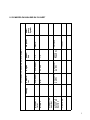
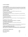
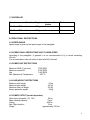
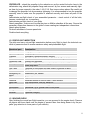
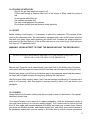
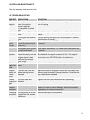
Table of Contents
1 IMPORTANT NOTICES ...................................................... 3
2 INSTRUCTIONS FOR USE .................................................. 4
3 SUPPLEMENTS ............................................................... 4
3.1 SUPPLEMENTING THE MANUAL - CHANGES
4
3.2 POWERED PARAGLIDER DATA SHEET
5
4 CONTROL ELEMENTS ...................................................... 6
4.1 FLIGHT CONTROLS
6
4.2 THROTLE CONTROL
6
4.3 IGNITION ON and OFF SWITCH
6
4.4 STARTER BUTTON
6
4.5 MASTER STARTER SWITCH
6
5. AIRCRAFT BASIC TECHNICAL DATA .................................. 6
6. PARAMOTOR SPECIFICATIONS ........................................ 7
7. EMERGENCY RESCUE PARACHUTE ................................. 7
7 PARAMOTOR PARTS AND EQUIPMENT................................ 7
7.1 ENGINE
7
7.2 PROPELLER
8
8 OPERATIONAL RESTRICTIONS .......................................... 8
8.1 SPEED RANGE
8
8.2 OPERATIONAL RESTRICTIONS DUE TO WIND SPEED
8
8.3 POWER UNIT RESTRICTIONS
8
8.4 LOAD WEIGHT RESTRICTIONS
8
8.5 POWER OUTPUT (model dependant)
8
8.6 OPERATIONAL G-LOAD FACTORS
9
8.7 OTHER OPERATIONAL RESTRICTIONS
9
9 EMERGENCY PROCEDURES.............................................. 9
9.1 ENGINE FAILURE (BELOW ALTITUDE OF 200 M)
9
9.2 ENGINE FAILURE (ABOVE THE ALTITUDE OF 200 m)
9
9.3 FIRE
9
9.4 VIBRATIONS
9
9.5 USE OF EMERGENCY SYSTEM
10
10 COMMON PROCEDURES ................................................10
10.1 TORQUE VALUES:
10
10.2 FLIGHT POSITION ADJUSTMENT OF THE SEAT
10
11 PRE-FLIGHT PREPARATION ............................................10
11.1 ASSEMBLY OF CAGE AND FRAME
10
11.2 PRE-FLIGHT INSPECTION
11
11.3 ENGINE CHECK
11
11.4 FILLING UP WITH FUEL
12
11.5 START
12
11.6 LAUNCH
12
11.7 ABORTING TAKE OFF
13
11.8 FLIGHT
13
11.9 FLIGHT IN TURBULENCE
13
11.10 TURNS
14
12 LANDING ....................................................................14
13 PACKING THE CANOPY..................................................14
14 ADJUSTMENT AND MAINTENANCE OF THE ENGINE ............14
14.1 BREAK-IN OF THE ENGINE
14
15 FUEL AND OIL ..............................................................14
15.1 CARBURATOR SETTING
15
16 REDUCTION BELT TIGHTENING .......................................15
17 PROPELLER ................................................................15
18 REGULAR MAINTENANCE ..............................................16
19 TROUBLESHOOTING .....................................................16
20 PARAMOTOR TRANSPORT .............................................17
20.1 ASSEMBLED
17
20.2 DISASSEMBLED
17
21 STORAGE ...................................................................17
21.1 SHORT TERM
17
21.2 LONG TERM - WINTER STORAGE
17
22 ILUSTRATIONS................................................................
23 GLIDER HOOK UP ADJUSTMENT .........................................
24 ENGINE PARTS DIAGRAM ..................................................
25 ELECTRICAL WIRING ........................................................
WARRANTY AND SERVICE MANUAL ....................................18
1 INTRODUCTION .............................................................18
2 START OF THE WARRANTY ..............................................18
2.1 WARRANTY CONDITIONS
18
2.2 WARRANTY REPAIRS PROCEDURE
19
2
2.3 WARRANTY TRANFER
19
2.4 APPLICATION OF WARRANTY
19
3. PRESCRIBED REPLACEMENT OF INDIVIDUAL PARTS ...........19
4. OBLIGATORY SERVICE EXAMINATIONS .............................20
5 SERVICE RECORDS ........................................................21
6 NOTES: .......................................................................22
1 IMPORTANT NOTICES
•
Observe the regulations of ultra-light aircraft operation.
•
Don’t overestimate your piloting abilities. Use suitable area s for landing and take offs
and practice emergency landings.
•
Watch for weather forecasts. Don’t set out for longer flights, if storms, fog, or showers
are to occur.
•
Observe the fuel content
•
When choosing the flight direction and altitude, you must always take into account the
possibility of an emergency landing.
•
Do not perform acrobatic manoeuvres.
•
Don’t underestimate navigation. Don’t fly cross-country without becoming familiar with
the navigation and without proper requisites (map, compass, GPS).
•
Set out for flight only when you are physically and mentally prepared.
3
2 INSTRUCTIONS FOR USE
1) The powered paraglider manufacturer issues this manual. Pilot is recommended to
have the manual with him/her when flying.
2) Records must be readable and no pages may be torn out.
3) Manual is a part of technical documentation together with new supplements.
4) Total number of flight hours and takeoffs + landings must be recorded in a logbook.
5) WJ paramotor dealer (inspector-technician) must be informed of any substation
damage to the paramotor! The dealer (inspector-technician) or the manufacturer will
recommend the method of repair, will supervise the repair and will carry out technical
check once repair is completed. A record must be made in the Service Records part of
the manual.
6) Any completed major repairs must be inspected and approved by Walkerjet paramotor dealer (inspector-technician)
7) The powered paraglider owner is responsible for of validity operational records.
8)
The Walkerjet paramotor dealer must approve all construction changes to a Powered
Paraglider. (Inspector-technician)
The owner, operator and the pilot of this powered paraglider must become familiar
with this operating manual.
3 SUPPLEMENTS
3.1 SUPPLEMENTING THE MANUAL - CHANGES
If there are any changes concerning the regulations or the PPG construction, a bulletin of
such changes will be sent or published on the Internet at www.walkerjet.cz web sites.
Every owner is obliged to carry out such changes and to make record of these changes in
this manual.
4
Other data
Place and
date of production
Czech Republic
RR
MODEL
Production
number
Walkerjet
Paramotor
Manufacturer
Canopy
Czech Republic
W 200
Walkerjet
Engine
Czech
Republic
1:3
1:3
Reduction
POWERED PARAGLIDER DATA SHEET
130 cm
Germany
HELIX
Propeller
Emergency
system
3.2 POWERED PARAGLIDER DATA SHEET
5
4 CONTROL ELEMENTS
4.1 FLIGHT CONTROLS
Powered Paraglider turns to the left by pulling left steering toggle down. Powered Paraglider
turns to the right by pulling right steering toggle down. Pulling both steering toggles simultaneously increases angle of attack, gliding ratio and decreases speed – be aware of stall (see
the paraglider manufacturer's manual).
4.2 THROTLE CONTROL
Right hand. Pushing the trigger increases RPM of the engine and vice versa.
4.3 IGNITION ON and OFF SWITCH
Right hand thumb. By switching the red button to the stop position, you will stop the engine.
4.4 STARTER BUTTON
Right hand index finger. By pressing and holding the button, you will start the engine. (Engines with electric starter only)
4.5 MASTER STARTER SWITCH
Right side. Switch placed on the bottom part of the frame. The switch disengages starter motor.
4.6 EMERGENCY RESCUE SYSTEM
Spare parachute - In front, between the comfort bars – if applicable.
4.7 SECONDARY IGNOTION SWITCH
Right hand thumb. Will switch ignition off if main ignition switch malfunctions.
4.8 CRUISE CONTROL
Right hand thumb. To engage push cruise button in until you hear click – this signifies cruise
control set. To cancel, apply full power gradually until cruise button releases.
4.8 PARAGLIDER TORQUE CONTROL TRIM
Left D riser - left hand. To apply (pull down) during flight at 50% or more power to eliminate
engine torque turn. Push cam buckle to release trim before landing or during thermal flights.
5. AIRCRAFT BASIC TECHNICAL DATA
Minimum flight weight (kg)
Maximum flight weight (kg
Fuel tank (litres)
60 kg
150 kg
13 L
6
6. PARAMOTOR SPECIFICATIONS
MODELS
ENGINE
HORSE POWER
REDUCTION
PROPELLER
WEIGHT
CARBURATOR
GAS TANK
CAGE PARTS
RR
W 200
25 HP
3:1
130 / 120 cm
28 / 26 kg
Wallbro 37
13 l
3
NOTE: Weight - paramotor without fuel.
7. EMERGENCY RESCUE PARACHUTE
Manufacturer
Model
Serial number
Way of activation
Descent Rate (m/s)
Maximum weight
7 PARAMOTOR PARTS AND EQUIPMENT
7.1 ENGINE
Type
W 200
Carburettor
WB 37
WALBRO WB-32
Cylinder volume
200 CC
Dry engine weight
10 kg
Engine and accessories weight
14 kg
Fuel
Unleaded gas 94 or 95
Mean consumption
4 litre per hour
Oil
Synthetic
Mixing ratio
40:1
Ignition
Electronic
Engine reduction
3:1
NOTE: W 200 engine is not certified as aircraft engine, a failure can occur anytime!
7
7.2 PROPELLER
Diameter
Material
Weight
1500 g
Number of
blades
3
130 Model RR
Carbon
120 Model RR
Carbon
Pitch
8
1400 g
3
11
8 OPERATIONAL RESTRICTIONS
8.1 SPEED RANGE
Speed range is given by the speed range of the paraglider.
8.2 OPERATIONAL RESTRICTIONS DUE TO WIND SPEED
According to the paraglider. In general it is not recommended to fly in winds exceeding
25 km/h.
It is not advisable to take off and/or to land with ANY tail wind.
8.3 POWER UNIT RESTRICTIONS
Maximum RPM (7 min max)
Maximum cruise RP
Idle
Max Operational Temperature
7 500 RPM
6 000 RPM
1 800 RPM
250 oC
8.4 LOAD WEIGHT RESTRICTIONS
Minimum pilot weight
Maximum pilot weight
Maximum take-off weight
Empty apparatus weight
60 kg
160 kg
150 kg
28 kg
8.5 POWER OUTPUT (model dependant)
Static thrust (propeller 110, 130)
85 kg
Mean climbing capacity
3 m/s
Ceiling
4000 m
Max Flight duration
3 hrs
Range
approximately 150 km
8
8.6 OPERATIONAL G-LOAD FACTORS
Maximum positive G-load factor in the centre of gravity - 1,0
Maximum negative G-load factor in the centre of gravity - 2,0
8.7 OTHER OPERATIONAL RESTRICTIONS
The paramotor can be operated in the temperature range of 0 °C +40 °C.
The frequency of paraglider canopy examinations is determined by the paraglider manufacturer. The paraglider manufacturer must determine the load-bearing lines examination frequency and possible replacement. If the manufacturer doesn't state otherwise, it is recommended to contact the manufacturer after 50 - 70 flight hours and to arrange the load-bearing
lines examination because the lines strength may have worsened.
ONLY VISUAL FLIGHT RULE FLIGHTS (WHEN THE GROUND IS
VISIBLE) ARE PERMITTED!
9 EMERGENCY PROCEDURES
9.1 ENGINE FAILURE (BELOW THE ALTITUDE OF 200 m)
-
Choose suitable emergency landing area and land.
9.2 ENGINE FAILURE (ABOVE THE ALTITUDE OF 200 m)
-
Check the fuel level
If fuel is present try to regenerate the fuel supply by squeezing primer bulb
Try to re-start the engine
If engine cannot be re-started choose suitable emergency landing area and land.
9.3 FIRE
-
Switch off the ignition
Land immediately.
9.4 VIBRATIONS
If unnatural vibrations occur:
9
-
Adjust the engine revolutions in such mode in which the vibrations are the smallest
Proceed to landing
If the vibrations are getting worse, immediately switch of the motor and prepare for
emergency landing
9.5 USE OF EMERGENCY SYSTEM
Spare parachute - If applicable. If the paraglider is definitely out of control such as uncontrollable spin or any other major flight failure, switch off the ignition, grasp the emergency parachute handle by your hand, and throw it to the left and behind or in the direction of the spin.
10 COMMON PROCEDURES
Each paramotor has been tested in operation. All connecting elements have been examined
carefully before the delivery. It is important to check and retighten all nuts of cylinder head
and exhaust pipe after 2 hours of operation when the nuts are finally properly seated due to
heat and vibration. The use of torque rench is absolutely necessary.
10.1 TORQUE VALUES
Cylinder head 9 Nm
Prop 15 Nm
Spark plug 20 Nm
All other M8 bolts 20 Nm
All other M6 bolts 10 Nm
10.2 FLIGHT POSITION ADJUSTMENT OF THE SEAT
Flight position adjustment of your seat must be carried out before the first flight. It is necessary to adjust the leg and shoulder strap lengths. Sitting position during flight is comfortable
when slightly tilted backwards. It is recommended to suspend the assembled paramotor to simulate the flight position and to try the transition from sitting position to the suspended position used for landing. The above-mentioned procedure will ensure an easy take-off, comfortable flight and safe landing. In the flight position the angle between the propeller and vertical
axis must be approximately 2º. Every pilot must adjust the flight position for his/her height
and weight.
11 PRE-FLIGHT PREPARATION
11.1 ASSEMBLY OF CAGE AND FRAME
Mount the left and right side of the cage. The bottom connection must be connected first – insert all the way. Connect top connector. If you have difficulties to assemble due to the tight
fit, position your self by the prop side of paramotor. Place one hand on frame and the other
on the cage section. Use your thumb to guide the male and female connector together.
Slide the top section(s) of the cage on the four connectors.
Connect the outside sides of the top frame to the side frames 2 connectors.
Attach comfort bars and harness shoulder buckles to the top of the frame.
Secure all 12 frame connections by Velcro straps. (6 on each side)
10
PROPELLER – attach the propeller to the reduction so as the central hole sits close to the
delimination ring, attach the propeller flange and secure it by four screws and manually tighten them by torque wrench in the order 1-4-2-5-3-6. See torque values above. Be careful not
to damage the propeller hub by excessive tightening. It is recommended to turn the propeller
manually once to make sure the propeller is attached correctly and clears all parts of the
cage.
Administrate pre-flight check of your assembled paramotor - visual control of all the bolts,
houses, connections etc. is necessary.
Administrate pre-flight check of your glider
Attach paraglider - make sure to screw the pins on Maillon shackles all the way. Secure the
secondary straps from harness to the glider’s risers creating two independent connections.
Attach speed system.
Re-check attchment of rescue parachute.
Double-check everything.
11.2 PRE-FLIGHT INSPECTION
The pilot must carry out pre-flight examination before every flight to check the technical condition of paramotor and to ensure maximum safety and pleasurable flight.
Examined part
Frame
Nylon Strings
Propeller
Motor
Reduction Gear
Other parts
Gas Tank
Harness
Emergency reserve
Oil
Gasoline
Motor test
Pilot
Instruments
Paraglider
Exhaust
Examination
Integrity, assembly
Integrity, tightness
Orientation, tightened screws, integrity
Silent blocks, carburettor bolts, exhaust bolts, Engine bolts
Screws, belt tightness
Overall condition, gasoline supply, electric contacts, switches,
spark plug cable
Tightness of fuel hoses and tank closure, tightness of bolts
Buckles, frame attachments
Attachment, pin, handle
Right mixture
Sufficient amount of fuel for flight – fresh mixture
High Revolutions, idle run, switch-off
Helmet, shoes, warm clothes, gloves,
Variometer, GPS, pocket radio or cell phone
Canopy condition, lines
Tightness, integrity
11.3 ENGINE CHECK
After finishing the overall pre-flight inspection, you can proceed to the engine check. Remove
all objects and loose items near the engine to prevent them from being drawn in by the propeller (pay attention to loose parts of your clothes).
11
11.4 FILLING UP WITH FUEL
- Only fill the gas tank when the engine is off
- Fill the tank through a filtration insert and, in the course of filling, check the purity of
fuel
- Do not smoke while filling up
- Use certified gas tanks only
- Use only funnel approved for gasoline
- Do not wear clothing that may produce static electricity
11.5 START
Before starting a cold engine, it is necessary to prime the carburettor. Tilt machine 45 degrees to the carburettor side. The carburettor is equipped with a vent at the bottom; plug this
vent with your index finger while squeezing the primer bulb. Squeeze the primer pump several times until the fuel drips out of the air filter and remove your index finger. Wait until most
fuel drips out. Tilt paramotor back.
WARNING: NEVER ATTMPT TO START THE ENGINE WITHOUT THE PROPELLER!!!
DO NOT STAND IN DANGEROUS PROXIMITY TO THE ENGINE, ESPECIALLY IN
FRONT OR ALONG THE SIDE OF THE PROPELLER.
Manual start: Grasp the recoil starter handle, place your foot on the bottom part of the paramotor stand hold the paramotor frame with left hand and start the engine by pulling the cord.
Electric start: place your left foot on the bottom part of the paramotor stand hold the paramotor frame with left hand and start the engine by pushing the start button.
After the engine starts running, warm it up in low and medium revolutions for 2 minutes until it
starts to run smoothly. After then engine is running smoothly, switch it off and hook in your
paraglider.
11.6 LAUNCH
Always launch into the wind, making sure that your path is clear of obstructions. Pay special
attention to power lines.
Your take-off stance is the same as in regular paragliding. Hold the accelerator handle in
your right hand (putting it on over the steering toggle). The A risers must be held at the link
level (in their upper part) wedged between the thumb and lower part of index finger. Stretch
your arms into medium position, with elbows slightly bent, and check your position relative to
the paraglider making sure you are exactly in its centre axis in order to ensure symmetrical
12
canopy inflation. To check your position proceed slightly forwards until the A lines are
stretched, your position is correct when you feel an equal pressure on both sides. Make
sure, at the same time, that you don't turn, otherwise you could hit your helper by the engine
or catch a paraglider line. The canopy inflation is done with the accelerator in idle position.
Before you begin raising your hands, lean against the front straps. Watch the paraglider rising, checking it visually without stopping. When the glider is above your head, release the risers and gradually apply full throttle. Make sure that you continue to run, while taking longer
and longer strides, with your back upright, until you are lifted off the ground. To reduce the
speed with which you have to run to attain lift-off speed of the glider, you may pull the brake
toggles down according to the current wind speed and direction. This will generate more lift
and aid your take off. For safety reasons, it is advisable to attain at least 10 meters of altitude, before trying let go of brake toggles or to drop speed system footrest. Should the engine quit while you are taking off, quickly apply brakes (flare) and run out the take-off attempt.
Reverse inflation:
For reverse inflation, grasp the brakes - they should be on top of the webbing risers. (The
right one with your right hand and the left one with your left hand) Your left hand should grab
the front lines (A) of the right side of paraglider (the way you face it) and your right hand
should grab the front lines (A) of the left side of paraglider. Perform reverse inflation and turn
180 degrees clockwise. Make sure the paraglider is inflated; you face into the wind direction start applying power. On a windy day you will be airborne within a few steps. On low wind
day it may take as many as 10 steps and you will have to apply full power and approximately
half brakes to get airborne. To reduce the speed with which you have to run to attain lift-off
speed of the glider, you may pull the brake toggles down according to the current wind speed
and direction. This will generate more lift and aid your take off. For safety reasons, it is advisable to attain at least 10 meters of altitude, before trying let go of brake toggles or to drop
speed system footrest. Should the engine quit while you are taking off, quickly apply brakes
(flare) and run out the take-off attempt.
11.7 ABORTING TAKE OFF
Abort take-off if the following occurs:
- Paraglider suffers asymmetric collapse
- Paraglider leading edge folds up (frontal collapse)
- Paraglider is not properly inflated
- Engine cannot achieve max. RPM
- Other unanticipated problems
11.8 FLIGHT
See the paraglider-operating manual
11.9 FLIGHT IN TURBULENCE
See the paraglider manual
13
11.10 TURNS
See the paraglider manual
12 LANDING
Watch the landing zone carefully, check for obstructions and direction of the wind. Always
land against into the wind.
Press the OFF switch and hold it until the engine stops at the altitude of at least 30m over the
ground. At 10 meters above ground, sit out of your harness and extend your legs with one
foot forward, ready to run. Flare 1 m over ground. Turn 180 degrees and collapse the paraglider in such a way as to prevent the contact of the canopy and lines with warm parts of the
engine.
13 PACKING THE CANOPY
• After landing fasten the toggles to the risers by means of magnet snaps. Unfasten the
canopy from the paramotor.
• First arrange the rear lines, than the front ones. When you proceed this way, you will
see that next time the lines will not be tangled. Insert risers to two different cells.
• Roll the canopy from the ears toward the centre so that the overall width of folded canopy is approximately equal to the width of the pack.
• Push the air from all channels. Fold the wing to make it fit in the pack.
14 ADJUSTMENT AND MAINTENANCE OF THE ENGINE
14.1 BREAK-IN OF THE ENGINE
Proper break-in of the engine is very important because of two reasons:
1) Check of regular function in all RPM modes
2) Proper warm-up of the engine and subsequent settling of all its parts
It is recommended to let the engine run on the ground in medium revolutions for 1 hour at
first and to accelerate from time to time to the full output for 1-2 sec, and then to slow to medium revolutions again. Towards the end of this testing hour, let the engine run at full revolutions for about 1 minute. It is important to keep the mix ratio according to the table below.
The engine will be ready for the first flight after this procedure.
It is recommended not to run the engine at the full output for a long time during the first flight
5 hours - use the full output for take off only (max 1 minute) and change the RPM during the
flight itself often. After 5 hrs of flight time, the engine is ready for non-restricted use.
15 FUEL AND OIL
The engine manufacturer and the company WALKERJET recommend using 100 % synthetic
oil in the proper mix ratio toalow for proper lubrication and to prevent carbonising of combustion and exhaust chambers. See table below. It is recommended not to store the fuel mixture
for longer than several days; the maximum storage time is 2-3 weeks. If the fuel mixture is
stored for longer time, the oil can get debased and there is a risk of engine seize-up.
14
MODE
Break-in
Regular operation
TIME
10 hours
10 and more hours
RATIO
1: 30
1: 40
Use exclusively leaded or unleaded gasoline with octane number 94 or 95
ANY MECHANICAL DEFECTS LEADING TO ENGINE SEIZE-UP ARE NOT SUBJECT TO WARRANTY
REPAIR. THESE DEFECTS ARE ALWAYS CAUSED BY NON-OBSERVANCE OF THE RUNNING-IN
REGULATIONS, USING NON-QUALITY FUEL OR OIL, USING WRONG MIX RATIO, OR BY ANY COMBINATION OF THESE FACTORS.
15.1 CARBURATOR SETTING
Setting is done by turning the HI or LO screws counterclockwise from the tightened (fully
closed) position of the screw. Be careful not to be too aggressive when turning HI or LO
screw clockwise looking for closed position as excessive torque could damage needle seat
inside carburettor.
MODEL RR
"L" screw
"H" screw
Standard
3/4 turn
1 1/4 turn
16 REDUCTION BELT TIGHTENING
Amount of the belt stretch between small and large pulley should range between 5 - 2 mm.
If you want to tighten the belt, loose the box nut, set the right tightness of the belt by turning
the eccentric shaft, then tighten the box nut to a stop.
17 PROPELLER
- Always store the propeller in a dry place
- Don’t expose the propeller to extreme temperature changes
- Store the propeller in horizontal position
- Don’t expose the propeller to sunshine without purpose
- Check the propeller after each flight. Any small nicks must be treated to prevent moisture penetration. You can carry out minor repairs, using appropriate procedure. After
the repair is finished, you must balance the propeller. Please, pay attention to the fact
that any propeller repair carried out by the customer is not subject to the warranty.
- Propeller should be balanced professionally after every 50 hrs of operation or if you
notice increased vibrations.
- Any adjustments or repairs carried out to the propeller by an unauthorized person can
lead to serious consequence including but not limited to strong vibrations, propeller
breakage and loss during flight, frame damage, reduction drive damage, other parts
damage).
15
18 REGULAR MAINTENANCE
See the warranty and service book.
19 TROUBLESHOOTING
DEFECT INDICATION
Flooded The engine doesn't
engine
start, the ignition
doesn't operate
It is possible to smell
fuel
The engine still doesn't
start
The engine still doesn't
start
Engine
The engine four-cycles
runs
in low revolutions (irrerough
gular run)
The engine four-cycles
in high revolutions
Incorrect The carburettor is adignition
justed correctly, but the
engine doesn't start
well and the engine
runs rough
Contami- The engine doesn't
nated air draw
filter
Engine
Prop will not turn 360
does not when starting button
crank
pressed
over
Loose
The belt slips and
reduction whistles
belt
Increasing vibrations
Damaged
propeller
Vibrating The propeller is not dapropeller maged but still causes
vibrations
SOLUTION
Manually turn the propeller 3 times against the direction of turning
Crank the engine over 5 times manually or by electric
starter
Pull out and dry the plug, turn the propeller 3 times in
the direction of turning
Tune up by carburettor "L" screw (see carburettor adjustment)
Tune up by carburettor "H" screw (see carburettor adjustment)
Ignition plug - check up contacts and clearance, adjust
the distance of magnet contacts (0.25). The engine
must have min. 600 RPM after it is started up.
Remove the air filter, blow it through, clean it up
Make sure prop is mounted. Motor will not crank over
without prop mounted! Charge batteries. Possible battery replacement needed.
Tighten the belt (see Reduction belt tightening)
In case of extensive damage, have the propeller replaced. In case of minor damage, have the propeller
repaired by an authorized person.
Static balancing of the propeller
16
20 PARAMOTOR TRANSPORT
20.1 ASSEMBLED
- Close the gas tank with transport cap
- Secure the paramotor against fall or damage
20.2 DISASSEMBLED
- Drain fuel from gas tank
- Close the tank by transport cap
- Disconnect the seat, disassemble the prop (if needed) cage and comfort bars
- It is recommended to use transport bag for protection
21 STORAGE
21.1 SHORT TERM
- Drain fuel from gas tank
- Close the tank by transport cap
- Turn the prop to horizontal position
21.2 LONG TERM - WINTER STORAGE
- Drain most of the fuel from gas tank
- Start the motor and run until at idle until it runs out of fuel
- Drain the remaining fuel from gas tank
- Turn the propeller to horizontal position or dismantle
- Store the paramotor in a dry and clean place with constant temperature
- Paramotor should be plugged in if possible during storage so the battery is fully
charged all the time. If you can’t have it plugged in make sure that you charge your
battery periodically - once a month even if the paramotor is not being used. This will
improve the life span of the battery.
17
WARRANTY AND SERVICE MANUAL
1 INTRODUCTION
Thank you for purchasing WALKERJET paramotor. We believe that WALKERJET paramotor
will satisfy your expectations and provide you with many years of flying.
WALKERJET company is acknowledged worldwide as a manufacturer of quality paramotors,
and with your new paramotor you will get more than simply the benefit of technical success
and experience gained from more than 10 years of innovation and PPG manufacturing.
It is necessary to read User Manual delivered together with your paramotor.
This WARRANTY AND SERVICE MANUAL contains details concerning the warranty and regular service examinations, which are necessary to maintain your paramotor performance during its service life.
Service work carried out by our workshop will be recorded in the service records. Always produce this book whenever you visit any WALKERJET workshop or dealer for the purpose of repair, order of parts or accessories.
2 START OF THE WARRANTY
WALKERJET support starts on the day when paramotor is handed over to the end user unless otherwise stated. Each new paramotor is subject to 12 months warranty.
Any defect arising during 12 months after the hand-over date as a consequence of workmanship or defective material will be repaired free of charge by the dealer you have purchased
the paramotor from.
WALKERJET will consider a claim for a warranty repair after the regular 12 months warranty
period in extraordinary conditions.
2.1 WARRANTY CONDITIONS
Service examinations to your paramotor must be carried out according to the service examination plan for individual models of WALKERJET paramotors and must be carried out exclusively by an authorized WALKERJET dealer.
Your paramotor must not be neglected, improperly used or modified. The maximum load stated in the manual mustn't be exceeded.
18
All Walkerjet paramotors and SKY Paragliders carry a 12 month manufacturer warranty for
manufacturing defects ONLY. Items NOT covered under this warranty may include:
•
•
•
•
•
•
Improper storage of paramotor and/or paraglider
Improper break in of paramotor resulting in engine seizure
Not following operating instructions as outlined in PPG course and or in Walkerjet
paramotor manual
Improper maintenance of paramotor and/or paraglider
Damage resulting from PPG accident
Damage resulting from normal wear and tear
2.2 WARRANTY REPAIRS PROCEDURE
Transport the complete unit to WALKERJET (authorized manufacturer) or authorized dealer
which will carry out the repair free of charge providing all warranty conditions have been followed and the warranty repair has been judged as justifiable.
2.3 WARRANTY TRANFER
If you sell the paramotor during the warranty period, the balance of the warranty is automatically transferred to the next owner.
2.4 APPLICATION OF WARRANTY
1. Please, read the operational manual carefully.
2. Carry out regular checks.
3. Always have your paramotor serviced in accordance with the service examination plan
published in this manual and have the service work recorded in appropriate place in
the service book.
4. Always have the service book with you at all regular and other service checks. The
service book is your paramotor history record and the manufacturer or authorized
WALKWERJET dealer will request it before starting any warranty repair or other services.
19
3. PRESCRIBED REPLACEMENT OF INDIVIDUAL PARTS
PARAMOTOR'S AGE
1
2
3
4
5
6
7
8
NUMBER OF FLOWN
HOURS
50
100
150
200
250
300
350
400
Primer Bulb
Reduction bearings
•
•
•
•
•
•
•
•
•
•
•
•
Reduction shaft
•
•
Engine bearings
Frame connection pins
•
•
•
•
Bolt re-tightening
•
•
•
•
Silent blocks
Main suspensions
•
•
•
•
•
•
•
•
Nylon strings
4. OBLIGATORY SERVICE EXAMINATIONS
PARAMOTOR'S AGE
NUMBER OF FLOWN
HOURS
OBLIGATORY SERVICE EXAMINATION
10
30
1
50
•
•
•
•
•
•
•
•
•
•
•
•
•
•
•
•
•
•
•
•
PROP BALANCING
PROP BALANCE
CHECK
•
•
2
100
3
150
4
200
5
250
6
300
20
5 SERVICE RECORDS
NUMBER OF
FLOWN HOURS
OBLIGATORY EXAMINATION
DATE
NUMBER OF
FLOWN HOURS
ADDITIONAL EXAM- OBLIGATORY EXINATION
AMINATION
DATE
NUMBER OF
FLOWN HOURS
OBLIGATORY EXAMINATION
DATE
NUMBER OF
FLOWN HOURS
ADDITIONAL EXAM- OBLIGATORY EXINATION
AMINATION
DATE
NUMBER OF
FLOWN HOURS
OBLIGATORY EXAMINATION
DATE
DATE
NUMBER OF
FLOWN HOURS
ADDITIONAL EXAM- OBLIGATORY EXINATION
AMINATION
ADDITIONAL EXAMINATION
ADDITIONAL EXAMINATION
ADDITIONAL EXAMINATION
21
SERVICE RECORDS
NUMBER OF
FLOWN HOURS
OBLIGATORY EXAMINATION
DATE
NUMBER OF
FLOWN HOURS
ADDITIONAL EXAM- OBLIGATORY EXINATION
AMINATION
DATE
NUMBER OF
FLOWN HOURS
OBLIGATORY EXAMINATION
DATE
NUMBER OF
FLOWN HOURS
ADDITIONAL EXAM- OBLIGATORY EXINATION
AMINATION
DATE
NUMBER OF
FLOWN HOURS
OBLIGATORY EXAMINATION
DATE
DATE
NUMBER OF
FLOWN HOURS
ADDITIONAL EXAM- OBLIGATORY EXINATION
AMINATION
ADDITIONAL EXAMINATION
ADDITIONAL EXAMINATION
ADDITIONAL EXAMINATION
22
SERVICE RECORDS
NUMBER OF
FLOWN HOURS
OBLIGATORY EXAMINATION
DATE
NUMBER OF
FLOWN HOURS
ADDITIONAL EXAM- OBLIGATORY EXINATION
AMINATION
DATE
NUMBER OF
FLOWN HOURS
OBLIGATORY EXAMINATION
DATE
NUMBER OF
FLOWN HOURS
ADDITIONAL EXAM- OBLIGATORY EXINATION
AMINATION
DATE
NUMBER OF
FLOWN HOURS
OBLIGATORY EXAMINATION
DATE
DATE
NUMBER OF
FLOWN HOURS
ADDITIONAL EXAM- OBLIGATORY EXINATION
AMINATION
ADDITIONAL EXAMINATION
ADDITIONAL EXAMINATION
ADDITIONAL EXAMINATION
23
SERVICE RECORDS
NUMBER OF
FLOWN HOURS
OBLIGATORY EXAMINATION
DATE
NUMBER OF
FLOWN HOURS
ADDITIONAL EXAM- OBLIGATORY EXINATION
AMINATION
DATE
NUMBER OF
FLOWN HOURS
OBLIGATORY EXAMINATION
DATE
NUMBER OF
FLOWN HOURS
ADDITIONAL EXAM- OBLIGATORY EXINATION
AMINATION
DATE
NUMBER OF
FLOWN HOURS
OBLIGATORY EXAMINATION
DATE
DATE
NUMBER OF
FLOWN HOURS
ADDITIONAL EXAM- OBLIGATORY EXINATION
AMINATION
ADDITIONAL EXAMINATION
ADDITIONAL EXAMINATION
ADDITIONAL EXAMINATION
24
SERVICE RECORDS
NUMBER OF
FLOWN HOURS
OBLIGATORY EXAMINATION
DATE
NUMBER OF
FLOWN HOURS
ADDITIONAL EXAM- OBLIGATORY EXINATION
AMINATION
DATE
NUMBER OF
FLOWN HOURS
OBLIGATORY EXAMINATION
DATE
NUMBER OF
FLOWN HOURS
ADDITIONAL EXAM- OBLIGATORY EXINATION
AMINATION
DATE
NUMBER OF
FLOWN HOURS
OBLIGATORY EXAMINATION
DATE
DATE
NUMBER OF
FLOWN HOURS
ADDITIONAL EXAM- OBLIGATORY EXINATION
AMINATION
ADDITIONAL EXAMINATION
ADDITIONAL EXAMINATION
ADDITIONAL EXAMINATION
25
SERVICE RECORDS
NUMBER OF
FLOWN HOURS
OBLIGATORY EXAMINATION
DATE
NUMBER OF
FLOWN HOURS
ADDITIONAL EXAM- OBLIGATORY EXINATION
AMINATION
DATE
NUMBER OF
FLOWN HOURS
OBLIGATORY EXAMINATION
DATE
NUMBER OF
FLOWN HOURS
ADDITIONAL EXAM- OBLIGATORY EXINATION
AMINATION
DATE
NUMBER OF
FLOWN HOURS
OBLIGATORY EXAMINATION
DATE
DATE
NUMBER OF
FLOWN HOURS
ADDITIONAL EXAM- OBLIGATORY EXINATION
AMINATION
ADDITIONAL EXAMINATION
ADDITIONAL EXAMINATION
ADDITIONAL EXAMINATION
26
6 NOTES:
27
6 NOTES:
28