1
@Home Radio
December 14, 2001
_____________________________________________________________________________
FM Audio Link
Authors:
Michael Guinn, Christopher Johns, Perry Minigh, and Travis Masoner
Project Sponsor:
Dr. Valenti
Service Manual
December 14, 2001
Version 1
Service Manual
Page 1 of 63
@Home Radio
December 14, 2001
_____________________________________________________________________________
Table of Contents
1. Introduction… … … … … … … … … … … … … … … … … .3
2. Subsystem Operation… … … … … … … … … … … … … ..6
a. PC Software… ...… … … … … … … … … … … … ..6
b. PIC Subsystem… … … … … … … … … … … … … 8
c. PIC Software… … … … … … … … … … … … … ...9
d. Transmitter Subsystem… … … … … … … … … .10
3. Circuit Schematics & Software Coding… … … ...… … 11
a. PC Code.… … … … … … … … … … … … … … … .11
b. PIC Subsystem Schematics… … ..… … .… … … 13
c. PIC Subsystem Code… … .… … … … … … … … .14
d. Transmitter Subsystem Schematic..… … … … ..15
e. Parts List… … … … … … … … … … … … … … … ..16
4. Adjustable Components… … … … … … … … … … … … .17
a. Transmitter Subsystem Potentiometer..… .… ..18
b. Transmitter Subsystem Inductor… … … … … ..19
5. Troubleshooting… … … … … … … … … … … … … … ..… 20
Version 1
Service Manual
Page 2 of 63
@Home Radio
December 14, 2001
_____________________________________________________________________________
1. Introduction
Welcome to the @Home Radio Audio Link Service Manual. This document is created to explain,
to a user with a background in computers and electronics, how the system operates and how to repair the
system should it fail. In the following pages we will discuss both hardware and software aspects of the
system.
As described in the user’s manual, @Home Radio is designed to transmit any stereo or audio
signal inputted to the device through its RCA-compatible jack, located on the rear side of the system box.
Any output frequency between 87.9 and 107.9 MHz can be selected (in 100 kHz increments). Since all
commercial stations broadcast on the “odd” tenths (example: 97.9 or 102.3), we have included the option of
transmitting on the “even” tenths (example: 88.8), doubling the number of output frequency levels. This
permits the user to better use small areas of open bandwidth. The current output frequency is displayed on
the four seven-segment displays on the front of the transmitter box.
The frequency can be controlled two ways – “on the box,” and through the use of a PC with the
packaged software. The transmitter box has buttons labeled “Up” and “Down.” These buttons, as
expected, raise and lower the frequency. By pressing and releasing one of these buttons, the frequency is
either incremented or decremented 100 kHz. The second method of controlling the frequency is with the
packaged @Home Radio software, which operates on any Windows platform. The PC will be connected to
the transmitter box through the serial cable provided with the system. The PC and transmitter
communicated via the RS-232 standard of operation. One convenient aspect of the system is that when the
PC is attached, the box buttons can still be used at the user’s convenience; they frequency shown on the PC
will be updated when the buttons are pressed.
Just like the frequency, the Stereo / Mono and Mute states of transmission can be controlled both
on the box and through the PC Software. Pressing and releasing the button marked “Stereo” on the box
toggles between stereo and monaural modes of transmission. In the same manner, pressing and releasing
the mute button toggles the mute state of transmission (a dead carrier signal is outputted) on and off.
Version 1
Service Manual
Page 3 of 63
@Home Radio
December 14, 2001
_____________________________________________________________________________
A simple audio player is packaged with the frequency control software for the user’s convenience.
If a user does not have or wish to use WinAmp or Microsoft’s Windows audio software, then the @Home
Radio software will easily suffice. It supports .wav, CD, and .mp3 playback formats, which the user selects
when loading a given file. While the file is playing, a counter is displayed that counts the number of
seconds the song has been playing.
One of the great advantages of the @Home Radio system is its high portability. It accepts a
standard 12 V DC input for power; the packaged AC adapter plugs into any home wall jack, and the
cigarette lighter permits use of the product in a car. As stated in the User’s Manual, a PC is not required
for system operation. For example, a user can attach the system to a discman in the front seat of his or her
car, power up the system with the cigarette lighter adapter, and listen to compact discs on the car’s FM
radio.
Version 1
Service Manual
Page 4 of 63
@Home Radio
December 14, 2001
_____________________________________________________________________________
2a. PC Software
The code described in this section is listed in section 3d of this Service Manual. The following
steps through the code function by function providing explicit detail that cannot be obtained from the
comments in the code.
Splash Screen Interface
The splash screen serves no purpose other than for aesthetics. When the @Home Radio GUI is
loaded, it appears on the screen; after 1.5 seconds or any key press, it disappears and the main window
appears. This is accomplished through the following functions:
?
Form_KeyPress(KeyAscii As Integer) – closes the Splash Screen Interface window when any
key is pressed.
?
Form_Load() – sets up the version label text box.
?
Frame1_Click() – closes the splash screen when the mouse clicks the within the frame.
?
Timer1_Timer – after 1500 milliseconds, it closes the Splash Screen Interface window.
Main Interface
All of the functionality that the GUI provides can be accessed from this window. It is both menu
and command button driven. The following is a detailed list of the functions provided by the main form:
?
Form_Load() – loads the Splash Screen Interface window; selects communication port 1; sets
port one for 2400 baud, no parity, 8 data, and 1 stop bit; sets the communications port control
to read the entire buffer on input; opens port 1; initializes testcomvar which is used to test
communications with the transmitter.
?
OpenPlayerCommand_Click() – loads the Audio Player Interface window.
?
ExitCommand_Click() – closes the GUI
?
MuteMenu_Click() – sends a message to transmitter to change mode of operation; changes the
display on the tool bar to fit the current state of the transmitter; changes the description of the
function on the drop down menus to fit the current state of the transmitter; loads the Dialog
Interface window with the appropriate message.
Version 1
Service Manual
Page 5 of 63
@Home Radio
December 14, 2001
_____________________________________________________________________________
?
SetFrequencyMenu_Click() – loads the Set Frequency Interface window.
?
MonoStereoMenu_Click() – sends a message to transmitter to change mode of operation;
changes the display on the tool bar to fit the current state of the transmitter; changes the
description of the function on the drop down menus to fit the current state of the transmitter;
loads the Dialog Interface window with the appropriate message.
?
TestCMenu_Click() – sends a message to the transmitter signaling a communications test;
loads the Communications Test Interface window.
?
AboutCommand_Click() – loads the Version Information Interface window.
?
SupportCommand_Click() – loads the User Help Interface window.
?
OpenPlayerButton_Click() – loads the Audio Player Interface window.
?
ChangeFreqButton_Click() – loads the Set Frequency Interface window.
?
UpIncrementButton_Click() – adds 1 kHz to the current broadcast frequency (if 107.9,
changes the value to 87.9); calls the private sub function TxFreq.
?
DnIncrementButton_Click() – subtracts 1 kHz from the current broadcast frequency (if 87.9,
changes the value to 107.9); calls the private sub function TxFreq.
?
MuteButton_Click() – sends a message to transmitter to change mode of operation; changes
the display on the tool bar to fit the current state of the transmitter; changes the description of
the function on the drop down menus to fit the current state of the transmitter; loads the
Dialog Interface window with the appropriate message.
?
MonoStereo_Click() – sends a message to transmitter to change mode of operation; changes
the display on the tool bar to fit the current state of the transmitter; changes the description of
the function on the drop down menus to fit the current state of the transmitter; loads the
Dialog Interface window with the appropriate message.
?
TestComm_Click() - sends a message to the transmitter signaling a communications test; loads
the Communications Test Interface window.
?
HelpButton_Click() - loads the User Help Interface window.
?
MSComm1_OnComm() – receives input from the communications port control; dissects input
to determine whether to change frequency or change mode of operation (i.e. mute the
Version 1
Service Manual
Page 6 of 63
@Home Radio
December 14, 2001
_____________________________________________________________________________
transmitter); according to the message, carries out appropriate function using the same
methods as described in the above functions (i.e. to change from mono to stereo).
Set Frequency Interface
This interface allows the user to manually type in a new frequency. It checks for errors (It will not
accept alphabetic characters or numeric characters smaller than 87.9 or larger than 107.9.). Once a valid
new frequency is received, it sends a message to the transmitter notifying it of the change and displays the
new frequency on Main Interface window. The following is the list of functions used to accomplish these
tasks:
?
cmdCancel_Click() – closes the Set Frequency Interface window and returns control to
the Main Interface window without making any changes or sending any messages to the
transmitter.
?
cmdOK_Click() – checks the user entered date for alphabetic or numeric characters
outside the desired range; if data is acceptable, changes the display on the Main Interface
window and sends a message to the transmitter notifying it of the change; if data is not
acceptable, loads the Error Interface window.
Error Interface
The Error Interface is used to alert the user of invalid data that was entered in the Set Frequency
Interface window. It is simply a dialog box that once closed, resets the entry blank on the Set Frequency
Interface window so that the data can be reentered. Below is the function used to accomplish this task:
?
cmdOK_Click() – resets the entry blank on the Set Frequency Interface Window; closes
the Error Interface window.
User Help Interface
The User Help Interface is used to act as a quick reference guide to the novice user of the @Home
Radio
system. It has a list of assumed typical questions that the user may have. By clicking on the question,
the user is given a brief answer. The user can view the different questions and answers and many times as
necessary without reopening the window. The functions listed below are used to accomplish these tasks:
?
Version 1
Form_Load() – initializes variables used to keep track of the two display modes.
Service Manual
Page 7 of 63
@Home Radio
December 14, 2001
_____________________________________________________________________________
?
Command1_Click() – changes the display from an answer back to the main list of
questions; retains the last answer displayed.
?
Command2_Click() – changes the display from the main list of questions to the last
answer displayed.
?
Command3_Click() – closes the User Help Interface and returns control to the Main
Interface window
?
List1_Click() – according to the question clicked on by the user, displays the answer.
Communications Test Interface
The Communications Test Interface is used to carry out the communications test between the GUI
and the transmitter. A signal is sent out serially by the GUI. The transmitter is then given 3000
milliseconds to respond. If it does not by the given time, an alert dialog appears and reports the test failed.
Otherwise, an alert dialog appears and reports the success of the test. The functions described below are
used to carry out these tasks:
?
Timer1_Timer() – waits to receive a signal from the transmitter for 3000 milliseconds; if
nothing is received or if communication was verified, displays the correct message.
?
CancelButton_Click() – closes the Communications Test Interface and the entire GUI.
?
OKButton_Click() – only enabled after a test has succeeded or failed; upon test failure, runs
the test again; upon test success, closes Communications Test Interface and returns control to
the Main Interface window.
Dialog Interface
The Dialog Interface is used to display alert messages to the user upon the transmitter changing
modes (i.e. changing from mono to stereo). It serves no other purpose and closes after 2500 milliseconds.
This is done using the following function:
?
Timer1_Timer() – after 2500 milliseconds, closes the Dialog Interface and returns control to
the Main Interface window.
Version Information Interface
Version 1
Service Manual
Page 8 of 63
@Home Radio
December 14, 2001
_____________________________________________________________________________
The Version Information Interface is used to display the current version information of the @Home
Radio
GUI. It serves no other purpose and after it is close, it returns control to the Main Interface window.
This task is done using the following function:
?
cmdOK_Click() – closes the Version Information Interface and returns control to the Main
Interface window.
Audio Player Interface
The Audio Player Interface is used to play audio files located on the PC. It is capable of playing
three file types: *.wav, *.mp3, and *.cda. If the device selected is the CD player, then it can advance
between tracks; otherwise, each song must be individually opened. This is done using the following
functions:
?
Form_Load() – initialize a variable that keeps track of the opened device; initializes the
devices to be used; initializes the variables used to display the music timer.
?
Mode_Click() – loads the Audio Selection Interface.
?
Open_Click() – when enabled (disabled when the selected device is a CD-ROM), loads a
common dialog box that opens files of the desired type (*.wav or *.mp3).
?
Timer1_Timer() – loads the correct .bmp file according to how much time has passed since
the audio player was started (operates the music timer).
?
Prev_Click() – “rewinds” the current track; if the track is “rewound”, plays the previous track;
resets music timer.
?
Play_Click() – plays the currently loaded track or file; signals the music timer to begin.
?
Pause_Click() – stops the play of the currently loaded track or file; disables the music timer
(keeps the display the same).
?
Stop_Click() – stops the play of the currently loaded track or file and “rewinds” it; disables
the music timer (resets the display).
?
Version 1
Next_Click() – plays the next track on the CD.
Service Manual
Page 9 of 63
@Home Radio
December 14, 2001
_____________________________________________________________________________
Audio Selection Interface
The Audio Selection Interface is used to open up a single audio device (i.e. CD–ROM). Once the
user selects to play one of the three supported file types, the interface is closed giving control to the Audio
Player Interface. This is done using the following functions:
?
List1_Click() – stores the user’s choice of audio source; closes the Audio Selection Interface
and give control to the Audio Player Interface.
Version 1
Service Manual
Page 10 of 63
@Home Radio
December 14, 2001
_____________________________________________________________________________
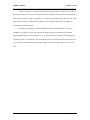
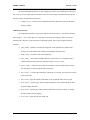
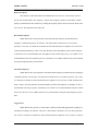
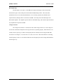
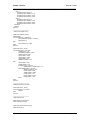
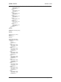
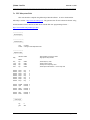
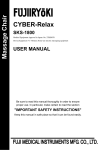
2b. PIC Subsystem
The 330 W resistor packs, 7447 BCD decoders, and PIC microcontroller are all placed into
sockets. The various capacitors, resistors, the oscillator, and the voltage regulator are also placed in sockets
for easy replacement. There are only a few items not placed in sockets – the diode needed for the voltage
regulator circuit is soldered directly to the +12 volt input and the 330 ? resistors needed for the power
indicator, stereo, and mute LED’s are soldered directly to the jumpers for those respective lights. All
socket pin connections are made with wire-wrap except for the PIC’s socket, which is soldered.
330 ?
330 ?
330 ?
330 ?
LED /
+5
Push
Bus
V.
Reg.
Cap.
V.
Reg.
7447
7447
7447
7447
GND
MAX
PIC 16F877
Misc.
Bus
232
#1
GND Bus #2
Figure 3. PIC System Board (Top)
Version 1
Service Manual
Page 11 of 63
@Home Radio
December 14, 2001
_____________________________________________________________________________
Ground Bus #1
This socket creates a bus by simply connecting the pins on the left side to those on the right with
small wire jumpers; that is, port 1 is connected to port 16, port 2 is attached to port 15, and so on. Ground
pins on the 7447 chips, PIC microcontroller, and MAX 232 chip are connected to this bus. The bus itself
gets its ground from the voltage regulator circuit.
Ground Bus #2
This socket is quite different from the first. The eight pins facing the middle of the board are tied
to ground, but the others are not connected. The grounds for all of the LED’s and pushbuttons on the front
of the box as well as the serial cable’s ground pin are connected here by pushing the jumpers down into the
socket.
+5 Bus
This bus is similar to Ground Bus in that all the pins on the left side are connected to those on the
right side with jumpers, except for pins 1 and 20. These two pins are connected with a 330 ? resistor, and
one end is tied to ground, rather than +5 volts. The other end is connected to pin 5 on the socket that
connects to the ones LED; this lights up the decimal point. All power connections for the system are
connected to this bus, which gets is connected directly to the output of the voltage regulator circuit.
Voltage Regulator Socket
The voltage regulator is placed in pins 6, 7, and 8, facing the middle of the board. Nothing else is
placed in this socket.
Voltage Regulator Capacitors Socket
The large 1000 ? F capacitor is placed in pins 1 and 3 (the positive end being in pin 1), and the 47
? F capacitor is placed in pins 9 and 10, with the positive leg placed in pin 10. No other connections are
made into this socket.
Version 1
Service Manual
Page 12 of 63
@Home Radio
December 14, 2001
_____________________________________________________________________________
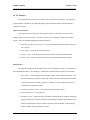
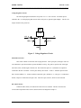
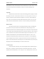
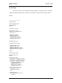
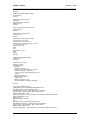
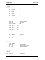
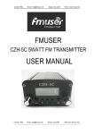
Voltage Regulator Circuit
The following diagram illustrates the setup of the +12 to +5 volt converter. The diode input is
soldered to the +12 volt input plug that connects to the wall jack (or cigarette lighter adapter). The five volt
output connects to the power bus.
Front
+12
+5
1000 ? F
47 ? F
GND
Figure 2. Voltage Regulator Circuit
Miscellaneous Socket
This socket contains several items with varying functions. The top ten pins (1 through 5 and 16 to
20) contain the 5 capacitors needed to operate the MAX 232 chip. The positive capacitor side is the right
side of the socket, and the negative the left side. The bottom four pins (9 to 12) hold the two capacitors
connected to the PIC’s oscillator. The two pins directly above them – 8 and 13 – hold the capacitor itself.
Pins 7 and 14 hold the 1 k? resistor needed to connect PIC pin 1 (MCLR) to +5 volts; pin 7 is connected to
the PIC, and pin 14 connected to the power bus. This leaves pins 6 and 15, which are not connected.
PIC 16F877 Socket
Unlike the other sockets, all connections to this circuit are soldered. The PIC connects to the
various other components in the circuit as shown in the circuit diagram in Chapter 3.
Version 1
Service Manual
Page 13 of 63
@Home Radio
December 14, 2001
_____________________________________________________________________________
MAX 232 Socket
This socket and chip connect to the other circuit components as diagrammed in Chapter 3.
7447 BCD Decoder Sockets
The inputs to these sockets connect to the PIC, and the outputs are tied to the 330 W resistor
packs. Power and ground, as with the other chips, are drawn from the power and ground buses.
330 W Resistor Packs
The resistors connect the pins on the left side to the pins directly across from them on the right
side. Only the 7447 decoders and seven segment displays are connected to these sockets.
Seven Segment Displays
These sockets are not “stuck” in the perf board; rather, they are simply wired to the resistor packs
and “hang” from the board. This permits ease of connection to the actual displays, which are glued to the
transmitter box itself.
LED / Pushbutton I/0 Socket
Only pins 1 through 6 are used in this socket. The frequency up button plugs into pin 1, and the
frequency down button is plugged into pin 2. Toggle stereo / mono plugs into pin 3, while toggle mute is
placed into pin 4. The positive end of the stereo / mono LED connects to pin 5 of this socket, leaving pin 6,
which connects to the mute LED. On the underside of the perf board, these pins are tied to the PIC as
specified in the circuit diagram.
Version 1
Service Manual
Page 14 of 63
@Home Radio
December 14, 2001
_____________________________________________________________________________
2c. PIC Software
The code described in this section is listed in section 3d of this Service Manual. The following
information steps through the code function by function, giving an more in-depth explanation than can be
realized from simply reading the commenting in the file.
Processor Declarations
Since we are using a PIC16F877, we select it and the corresponding include file here.
Register Usage
Dlay refers to a delay used to debounce the pushbuttons. Freq, count, and oldfrq are simple
register variables used to store a single byte of data each. The #define freq declarations assign a name to
represent each bit of the stored frequency value. This allows for easy bit checking. The following six
#define statements assign a name to the frequency up button, frequency down button, stereo button, mute
button, stereo LED, and mute LED for easy checking and setting.
Code Origin
The org call starts the code at location 0, the first available spot.
Port Setup
At register page 0, all five I/O ports are cleared for initialization. Then, at register page 1, Analog
to Digital conversion for port A is disabled, port A is set to output, port B is set up for input at bits 0
through 5 and output at bits 6 and 7, and ports C, D, and E are set for output. The serial transmit and
receive pins on port C are activated and set to asynchronous transmission at a baud rate of 2400. Receive is
finally enabled at register page 0.
Run Once at Start
This section initializes the frequency to 87.9 MHz and enables stereo transmission while disabling
the mute setting. It also sends this frequency setting to the PC.
Version 1
Service Manual
Page 15 of 63
@Home Radio
December 14, 2001
_____________________________________________________________________________
Main Code
The main code section is actually very short. First, the receive register is checked to see if the
frequency has been changed on the PC. If it has, it jumps to the check frequency section. If not, it checks
all four of the input buttons on the box in sequence. If none of the buttons have been pressed, then the
main code restarts. If a button has been pressed, the code jumps to a debounce routine for the particular
pushbutton that was activated.
Check Input
Here, the upper nibble of the input from the PC is checked to see if it is 1111. If it is, then this
designates a special opcode from the PC has been sent rather than a new frequency. If bit 2 is set, then the
PC is asking for a communication test; we jump to a section in the code that sends back exactly what the
PC transmitted – 11110100. Bit 1 is then checked. If bit 1 is set, then a mute setting has been received. If
it is clear, a stereo / mono setting has been inputted. The code then jumps to a section for either a mute or
stereo setting, depending on this bit.
Test Communication
Here, a hexadecimal F4 is sent in response to the PC’s call for a communication test.
Transmission is enabled, hex F4 is loaded, then it is sent via the transmit register. A loop then repeatedly
checks the transmit buffer to see if it is empty; if it is not, a small delay routine is called. Once the buffer is
emptied and transmission is finished, transmission is disabled. The program then returns to the main code.
PC Set Stereo
This function changes the stereo setting based on input from the PC. Bit 0 of the data sent from
the PC is checked. If the bit is set, stereo is turned on, if it is clear, the stereo LED is turned off.
PC Set Mute
This function changes the mute setting based on input from the PC. Bit 0 of the data sent from the
PC is checked. If the bit is set, mute is turned on, if it is clear, the mute LED is turned off.
Version 1
Service Manual
Page 16 of 63
@Home Radio
December 14, 2001
_____________________________________________________________________________
Restore Frequency
This function is called from either test communication, PC set stereo, or PC set mute, since an
opcode was sent rather than a new frequency. The previous frequency, which was stored in the variable
oldfrq, is loaded back into the variable freq, resetting the frequency back to what it was before the PC data
was received. We jump back to the main code.
Decrement Frequency
Within this function, the down button is debounced and the frequency decremented before
jumping to a transmit frequency to PC function. The down button is checked to see if it is still set
(pressed). If it is clear, it’s checked a second time to ensure the debounce has completed. If it is not clear,
a small 20-millisecond delay is called. Once this debounce routine has finished, each bit of the frequency
is checked to see if it is the minimum value (all eight bits of the variable freq zeroes), or 87.9 MHz. If it is
at this minimum value, the variable freq is set to 11001000, or 107.9 MHz; otherwise, freq is decremented,
moving the output frequency down 100 kHz.
Increment Frequency
Within this function, the up button is debounced and the frequency incremented before jumping to
a transmit frequency to PC function. The up button is checked to see if it is still set (pressed). If it is clear,
it’s checked a second time to ensure the debounce has completed. If it is not clear, a small 20-millisecond
delay is called. Once this debounce routine has finished, each bit of the frequency is checked to see if it is
the maximum value (freq is equal to 11001000), or 107.9 MHz. If it is at this maximum value, the variable
freq is set to all zeroes, or 87.9 MHz; otherwise, freq is incremented, moving the output frequency up 100
kHz.
Toggle Stereo
Within this function, the stereo / mono button is debounced and LED toggled before jumping to a
transmit stereo setting to PC function. The stereo / mono button is checked to see if it is still set (pressed).
If it is clear, it’s checked a second time to ensure the debounce has completed. If it is not clear, a small 20-
Version 1
Service Manual
Page 17 of 63
@Home Radio
December 14, 2001
_____________________________________________________________________________
millisecond delay is called. Once this debounce routine has finished, the stereo LED is checked. If it is set
(on), the LED is turned off for mono transmission. Otherwise, it is turned on, indicating a stereo
transmission.
Toggle Mute
Within this function, the mute button is debounced and LED toggled before jumping to a transmit
mute setting to PC function. The mute button is checked to see if it is still set (pressed). If it is clear, it’s
checked a second time to ensure the debounce has completed. If it is not clear, a small 20-millisecond
delay is called. Once this debounce routine has finished, the mute LED is checked. If it is set (on), the
LED is turned off for normal transmission. Otherwise, it is turned on, indicating a muted transmission.
Display Frequency
This function sets ports D and E to correctly display the frequency setting. Port D displays the
decimals and ones, while port E contains the tens and hundreds data. Initially, the high byte of the
decimals and ones table location is loaded into the program counter. Then the table is called, which returns
a value a number of steps down the table based in the value stored in the variable freq. That is, if freq is all
zeroes, it returns the first value in the table, the data needed to display the seven and nine in 87.9. If it is
00000010, it returns the third value, which contains the data needed to display 88.1, and so on. The
returned value for the decimals and ones is then sent to port D, as stated above. The tens and hundreds
values are displayed in the same manner – the high value of the table is loaded, the code jumps the same
number of values down in this table as it did in the previous one, and the returned value is moved to port E,
displaying the correct tens and hundreds digits. The code now returns to main.
Transmit Frequency
The data stored in the variable freq is sent to the PC through this function, which then jumps to a
display routine. Transmission is enabled, and the freq is loaded into the transmit register. A loop then
repeatedly checks the transmit buffer to see if it is empty; if it is not, a small delay routine is called. Once
Version 1
Service Manual
Page 18 of 63
@Home Radio
December 14, 2001
_____________________________________________________________________________
the buffer is emptied and transmission is finished, transmission is disabled. The program then jumps to the
aforementioned display code.
Transmit Stereo Setting
This function sends the stereo / mono state serially to the PC. Transmission is enabled, and the
stereo LED is checked. If it is on, hexadecimal F1, the opcode for set stereo, is loaded to the transmit
register. Otherwise, hexadecimal F0, the opcode for mono transmission, is loaded to the transmit buffer.
As in all of the other serial transmission functions, a loop repeatedly checks the transmit buffer. A delay is
called until the buffer is empty, at which point the transmission is disabled since it is finished. We then
jump back to the main code.
Transmit Mute Setting
This function sends the mute state serially to the PC. Transmission is enabled, and the mute LED
is checked. If it is on, hexadecimal F2, the opcode for set mute, is loaded to the transmit register.
Otherwise, hexadecimal F3, the opcode for normal transmission, is loaded to the transmit buffer. Again, a
loop repeatedly checks the transmit buffer. A delay is called until the buffer is empty, at which point the
transmission is disabled since it is finished. We then jump back to the main code.
Delay
This is called by all of the transmit routines. Hexadecimal FF is loaded into a counter variable,
and it is repeatedly decremented though a loop until it is equal to zero. The program then returns to its
previous location
Data Read
This function is not currently used.
Data Write
This function is not currently used.
Version 1
Service Manual
Page 19 of 63
@Home Radio
December 14, 2001
_____________________________________________________________________________
Decimals and Ones
This table begins at register address 300 to avoid paging errors in the high byte of the program
counter. It returns a value that will display the correct decimals and ones values through the use of BCD
decoders.
Tens and Hundreds
This table begins at register address 600 to avoid paging errors in the high byte of the program
counter. It returns a value that will display the correct tens and hundreds values through the use of BCD
decoders.
Version 1
Service Manual
Page 20 of 63
@Home Radio
December 14, 2001
_____________________________________________________________________________
2d. Transmitter Subsystem
The transmitter portion of the @Home Radio is laid out on a printed circuit board. The peripheral
connections are power, ground, lines to the PIC microprocessor, and RF output to the antenna. The
complete schematic for the transmitter subsystem can be seen in section 3d of this service manual.
Nonstandard components (resistors, capacitors, crystals, etc.) are listed below.
Description
Darlington Transistor
Varactor Diode
Band Pass Filter
Variable Inductor
Stereo Modulator – RF generator
RF Amplifier
Manufacturer
ROHM
TOKO
SOSHIN
SUMIDA
ROHM
RF Micro Devices
Part #
2SC2062S
KV1471E
GFWB3
FEM10C-3F6
BH1415F
RF2334
Audio Input
The audio input is done through standard RCA Jacks. One being a left channel and the other the
right channel. This input is filtered by the BH1415F chip with a low pass filter before being added (L+R)
and subtracted (L-R) by the chip. The multiplexed stereo (or mono when mono is on) output is observed at
pin 5 of the BH1415F. This is connected to a potentiometer for desired attenuation, and fed to the rest of
the circuit.
Phase Lock Loop (PLL)
The BH1415F chip implements a phase lock loop system that contains some components that are
off-chip. The goal of the PLL is to allow the user to serially select the operating frequency, and to adjust
the RF output frequency accordingly. The serial data is input via pins 15, 16, and 17 on the BH1415F. For
specifics on programming the serial input please refer to the BH1415F data sheet included with this
manual.
Voltage Controlled Oscillator
The voltage controlled oscillator (VCO) portion that is contained outside of the BH1415F consists
of the parallel network with the varactor diode and variable inductor. The inductor can be adjusted with a
tuning want to vary the resonant frequency of the VCO. This can be used to calibrate the digital frequency
settings.
Version 1
Service Manual
Page 21 of 63
@Home Radio
December 14, 2001
_____________________________________________________________________________
RF Output Stage
The RF output is seen at pin 11 of the BH1415F and passes through a resistor network that
attenuates the signal. This is then passed to the Soshin GFWB6 band pass filter. This assures that
transmission does not exceed the desired FM band. In case of Faulty operation, the GFWB6 can be
replaced with any band pass filters out all but 88-108 MHz. The final portion of the RF output is the
RF2334 RF amplifier. This amplifier operates in the DC-4000 MHz range, and could be replaced with and
any amplifier that accepts 88-108 MHz.
Voltage Test Point
The voltage between the two 3.3K resistors is the control voltage for the VCO. This voltage can
be observed to determine if the phase lock loop system (PLL) is operating properly. When the PLL is not
locked (occurs on power up, or when a new frequency has been selected), the test voltage should either
raise from a low voltage to +5 or lower from +5 to close to zero volts. This is when the PLL is searching
for the frequency to lock on. Once the PLL finds the correct frequency the control voltage should stabilize
and no longer vary.
Version 1
Service Manual
Page 22 of 63
@Home Radio
December 14, 2001
_____________________________________________________________________________
3a. PC Code
This section contains code for both the audio player and the PC’s transmitter control. It should be
compiled with Microsoft Visual Basic 6.0, which can be found in the Microsoft Visual Studio software
package.
''''''''''''''''''''''''''''''''''''''''''''''''''''''''''''''''''''''
' About Form Code
Private Sub cmdOK_Click()
Unload AboutForm
End Sub
' Audio Player Form Code
Private Sub Form_Load()
' Initialize Device Type (Error Chex)
DeviceType = -1
' Initialize Clock Variables
AudioPlayer.Counter = 0
AudioPlayer.Clock_Tens = 0
AudioPlayer.Clock_Minutes = 0
AudioPlayer.Clock_Hours = 0
AudioSelection.Show (1)
' Use MMControl for CD Audio
MMControl1.Notify = False
MMControl1.Wait = True
MMControl1.Shareable = False
MMControl1.DeviceType = "CDAudio"
MMControl1.Command = "Open"
End Sub
Private Sub Mode_Click()
AudioSelection.Show (1)
End Sub
Private Sub Next_Click()
Hours.Picture = LoadPicture("A:\0.bmp")
Minutes.Picture = LoadPicture("A:\0.bmp")
Tens.Picture = LoadPicture("A:\0.bmp")
Ones.Picture = LoadPicture("A:\0.bmp")
AudioPlayer.Counter = 0
AudioPlayer.Clock_Tens = 0
AudioPlayer.Clock_Minutes = 0
AudioPlayer.Clock_Hours = 0
' Be sure device has been selected.
If DeviceType = -1 Then
AudioSelection.Show (1)
End If
' Select Correct Device
If AudioPlayer.DeviceType = 0 Then
' Do Nothing!
Version 1
Service Manual
Page 23 of 63
@Home Radio
December 14, 2001
_____________________________________________________________________________
Else
MMControl1.Command = "Next"
End If
End Sub
Private Sub Open_Click()
Select Case AudioPlayer.DeviceType
Case 0
CommonDialog1.Filter = "*.mp3|*.mp3"
CommonDialog1.ShowOpen
If CommonDialog1.FileName <> "" Then
AP.FileName = CommonDialog1.FileName
AP.Play
End If
Case 1
CommonDialog1.Filter = "*.cda|*.cda"
CommonDialog1.ShowOpen
If CommonDialog1.FileName <> "" Then
MMControl1.FileName = CommonDialog1.FileName
MMControl1.Command = "Play"
End If
Case 2
CommonDialog1.Filter = "*.wav|*.wav"
CommonDialog1.ShowOpen
If CommonDialog1.FileName <> "" Then
AP.FileName = CommonDialog1.FileName
AP.Play
End If
End Select
If CommonDialog1.FileName <> "" Then
Hours.Picture = LoadPicture("A:\0.bmp")
Minutes.Picture = LoadPicture("A:\0.bmp")
Tens.Picture = LoadPicture("A:\0.bmp")
Ones.Picture = LoadPicture("A:\0.bmp")
Timer1.Enabled = True
End If
End Sub
Private Sub Pause_Click()
Timer1.Enabled = False
' Be sure device has been selected.
If DeviceType = -1 Then
AudioSelection.Show (1)
End If
' Select Correct Device
If AudioPlayer.DeviceType = 0 Then
AP.Pause
Else
MMControl1.Command = "Pause"
End If
End Sub
Private Sub Play_Click()
' Be sure device has been selected.
If DeviceType = -1 Then
AudioSelection.Show (1)
End If
' Select Correct Device
If AudioPlayer.DeviceType = 0 Then
If AP.FileName <> "" Then
AP.Play
If AudioPlayer.Counter = 0 Then
Hours.Picture = LoadPicture("A:\0.bmp")
Minutes.Picture = LoadPicture("A:\0.bmp")
Tens.Picture = LoadPicture("A:\0.bmp")
Ones.Picture = LoadPicture("A:\0.bmp")
End If
Version 1
Service Manual
Page 24 of 63
@Home Radio
December 14, 2001
_____________________________________________________________________________
Timer1.Enabled = True
End If
Else
If 1 Then
MMControl1.Command = "Play"
If AudioPlayer.Counter = 0 Then
Hours.Picture = LoadPicture("A:\0.bmp")
Minutes.Picture = LoadPicture("A:\0.bmp")
Tens.Picture = LoadPicture("A:\0.bmp")
Ones.Picture = LoadPicture("A:\0.bmp")
End If
Timer1.Enabled = True
End If
End If
End Sub
Private Sub Prev_Click()
Hours.Picture = LoadPicture("A:\0.bmp")
Minutes.Picture = LoadPicture("A:\0.bmp")
Tens.Picture = LoadPicture("A:\0.bmp")
Ones.Picture = LoadPicture("A:\0.bmp")
AudioPlayer.Counter = 0
AudioPlayer.Clock_Tens = 0
AudioPlayer.Clock_Minutes = 0
AudioPlayer.Clock_Hours = 0
' Be sure device has been selected.
If DeviceType = -1 Then
AudioSelection.Show (1)
End If
' Select Correct Device
If AudioPlayer.DeviceType = 0 Then
' Do Nothing!
Else
MMControl1.Command = "Prev"
End If
End Sub
Private Sub Stop_Click()
Timer1.Enabled = False
' Be sure device has been selected.
If DeviceType = -1 Then
AudioSelection.Show (1)
End If
' Select Correct Device
If AudioPlayer.DeviceType = 0 Then
AP.Stop
AudioPlayer.Counter = 0
AudioPlayer.Clock_Tens = 0
AudioPlayer.Clock_Minutes = 0
AudioPlayer.Clock_Hours = 0
Else
MMControl1.Command = "Stop"
MMControl1.Command = "Prev"
AudioPlayer.Counter = 0
AudioPlayer.Clock_Tens = 0
AudioPlayer.Clock_Minutes = 0
AudioPlayer.Clock_Hours = 0
End If
Version 1
Service Manual
Page 25 of 63
@Home Radio
December 14, 2001
_____________________________________________________________________________
End Sub
Private Sub Timer1_Timer()
' Increment Counter
AudioPlayer.Counter = AudioPlayer.Counter + 1
If AudioPlayer.Counter < 10 Then
Select Case AudioPlayer.Counter
Case 0
Ones.Picture = LoadPicture("A:\0.bmp")
Case 1
Ones.Picture = LoadPicture("A:\1.bmp")
Case 2
Ones.Picture = LoadPicture("A:\2.bmp")
Case 3
Ones.Picture = LoadPicture("A:\3.bmp")
Case 4
Ones.Picture = LoadPicture("A:\4.bmp")
Case 5
Ones.Picture = LoadPicture("A:\5.bmp")
Case 6
Ones.Picture = LoadPicture("A:\6.bmp")
Case 7
Ones.Picture = LoadPicture("A:\7.bmp")
Case 8
Ones.Picture = LoadPicture("A:\8.bmp")
Case 9
Ones.Picture = LoadPicture("A:\9.bmp")
End Select
Else
AudioPlayer.Counter = 0
Ones.Picture = LoadPicture("A:\0.bmp")
AudioPlayer.Clock_Tens = AudioPlayer.Clock_Tens + 1
If AudioPlayer.Clock_Tens < 6 Then
Select Case AudioPlayer.Clock_Tens
Case 0
Tens.Picture = LoadPicture("A:\0.bmp")
Case 1
Tens.Picture = LoadPicture("A:\1.bmp")
Case 2
Tens.Picture = LoadPicture("A:\2.bmp")
Case 3
Tens.Picture = LoadPicture("A:\3.bmp")
Case 4
Tens.Picture = LoadPicture("A:\4.bmp")
Case 5
Tens.Picture = LoadPicture("A:\5.bmp")
End Select
Else
AudioPlayer.Clock_Tens = 0
Tens.Picture = LoadPicture("A:\0.bmp")
AudioPlayer.Clock_Minutes = AudioPlayer.Clock_Minutes + 1
If AudioPlayer.Clock_Minutes < 10 Then
Select Case AudioPlayer.Clock_Minutes
Case 0
Minutes.Picture = LoadPicture("A:\0.bmp")
Version 1
Service Manual
Page 26 of 63
@Home Radio
December 14, 2001
_____________________________________________________________________________
Case 1
Minutes.Picture = LoadPicture("A:\1.bmp")
Case 2
Minutes.Picture = LoadPicture("A:\2.bmp")
Case 3
Minutes.Picture = LoadPicture("A:\3.bmp")
Case 4
Minutes.Picture = LoadPicture("A:\4.bmp")
Case 5
Minutes.Picture = LoadPicture("A:\5.bmp")
Case 6
Minutes.Picture = LoadPicture("A:\6.bmp")
Case 7
Minutes.Picture = LoadPicture("A:\7.bmp")
Case 8
Minutes.Picture = LoadPicture("A:\8.bmp")
Case 9
Minutes.Picture = LoadPicture("A:\9.bmp")
End Select
Else
AudioPlayer.Clock_Minutes = 0
Minutes.Picture = LoadPicture("A:\0.bmp")
AudioPlayer.Clock_Hours = AudioPlayer.Clock_Hours + 1
If AudioPlayer.Clock_Hours < 6 Then
Select Case AudioPlayer.Clock_Hours
Case 0
Hours.Picture = LoadPicture("A:\0.bmp")
Case 1
Hours.Picture = LoadPicture("A:\1.bmp")
Case 2
Hours.Picture = LoadPicture("A:\2.bmp")
Case 3
Hours.Picture = LoadPicture("A:\3.bmp")
Case 4
Hours.Picture = LoadPicture("A:\4.bmp")
Case 5
Hours.Picture = LoadPicture("A:\5.bmp")
End Select
Else
AudioPlayer.Clock_Hours = 0
Hours.Picture = LoadPicture("A:\0.bmp")
End If
End If
End If
End If
End Sub
''''''''''''''''''''''''''''''''''''''''''''''''''''''''''''''''''''''
' Audio Selection Code
Private Sub List1_Click()
Select Case List1.ListIndex
Case 0
AudioPlayer.DeviceType = 1
AudioPlayer.Open.Enabled = False
AudioPlayer.Prev.Enabled = True
AudioPlayer.Next.Enabled = True
Version 1
Service Manual
Page 27 of 63
@Home Radio
December 14, 2001
_____________________________________________________________________________
Case 1
AudioPlayer.DeviceType = 0
AudioPlayer.Open.Enabled = True
AudioPlayer.Prev.Enabled = False
AudioPlayer.Next.Enabled = False
Case 2
AudioPlayer.DeviceType = 2
AudioPlayer.Open.Enabled = True
AudioPlayer.Prev.Enabled = False
AudioPlayer.Next.Enabled = False
End Select
Me.Hide
End Sub
''''''''''''''''''''''''''''''''''''''''''''''''''''''''''''''''''''''
' Test Communication Code
Private Sub OKButton_Click()
Unload Dialog
If Form1.testcomvar = False Then
Form1.MSComm1.Output = Chr(244)
Dialog.Show (1)
Else
Form1.testcomvar = False
End If
End Sub
Private Sub Timer1_Timer()
If Form1.testcomvar = True Then
TestBar.Value = 100
CancelButton.Enabled = False
TestBar.Visible = False
Label1.Visible = False
Label2.Visible = False
Label4.Visible = True
OKButton.Enabled = True
Else
Label1.Visible = True
TestBar.Visible = True
If TestBar.Value < 100 Then
TestBar.Value = TestBar.Value + 10
ElseIf TestBar.Value = 100 Then
OKButton.Enabled = True
Label1.Visible = False
TestBar.Visible = False
Label2.Visible = True
Image1.Visible = False
Image2.Visible = True
End If
End If
End Sub
''''''''''''''''''''''''''''''''''''''''''''''''''''''''''''''''''''''
' Mute/Mono/Stereo Form Code
Private Sub Timer1_Timer()
If Form1.tmpfreq2 <> 244 Then
Me.Hide
End If
End Sub
''''''''''''''''''''''''''''''''''''''''''''''''''''''''''''''''''''''
' Main Window Code
Public testcomvar As Boolean
Public tmpfreq2 As Variant
Private Sub AboutCommand_Click()
AboutForm.Show (1)
Version 1
Service Manual
Page 28 of 63
@Home Radio
December 14, 2001
_____________________________________________________________________________
End Sub
Private Sub ChangeFreqButton_Click()
Form2.Show (1)
End Sub
Private Sub Command1_Click()
Dialog.Hide
MSComm1.Output = Chr(244)
Dialog.Show (1)
End Sub
Private Sub ContentsCommand_Click()
helpwin.Show (1)
End Sub
Private Sub Command2_Click()
Form4.Show (1)
End Sub
Private Sub DnIncrementButton_Click()
If FreqText.Text > 87.9 Then
FreqText.Text = FreqText.Text - 0.1
If (FreqText.Text - Int(FreqText.Text)) = 0 Then
Tmp = FreqText.Text & ".0"
FreqText.Text = Tmp
End If
Else
FreqText.Text = 107.9
End If
TxFreq
End Sub
Private Sub ExitCommand_Click()
Unload Form1
End Sub
Private Sub Form_Load()
testcomvar = False
frmSplash.Show (1)
' Use COM1.
MSComm1.CommPort = 1
' 2400 baud, no parity, 8 data, and 1 stop bit.
MSComm1.Settings = "2400,N,8,1"
' Tell the control to read entire buffer when Input
' is used.
MSComm1.InputLen = 1
MSComm1.RThreshold = 1
' Open the port.
MSComm1.PortOpen = True
' Send the attention command to the modem.
End Sub
Private Sub MonoStereo_Click()
If MonoStereo.Picture = MonoStereo.DisabledPicture Then
MonoStereo.Picture = MonoStereo.DownPicture
MonoStereoMenu.Caption = "Ch&ange to Mono Transmission"
Dialog1.Caption = "@Home Radio - Mono / Stereo Select"
Dialog1.Label1.Visible = False
Dialog1.Label2.Caption = "The transmitter is now broadcasting a Stereo audio signal."
Dialog1.Label2.Visible = True
Dialog1.Show (1)
MSComm1.Output = Chr(241)
Else
MonoStereo.Picture = MonoStereo.DisabledPicture
MonoStereoMenu.Caption = "Ch&ange to Stereo Transmission"
Dialog1.Caption = "@Home Radio - Mono / Stereo Select"
Dialog1.Label1.Visible = False
Dialog1.Label2.Caption = "The transmitter is now broadcasting a Mono audio signal."
Version 1
Service Manual
Page 29 of 63
@Home Radio
December 14, 2001
_____________________________________________________________________________
Dialog1.Label2.Visible = True
Dialog1.Show (1)
MSComm1.Output = Chr(240)
End If
End Sub
Private Sub MonoStereoMenu_Click()
If MonoStereo.Picture = MonoStereo.DisabledPicture Then
MonoStereo.Picture = MonoStereo.DownPicture
MonoStereoMenu.Caption = "Ch&ange to Mono Transmission"
Dialog1.Caption = "@Home Radio - Mono / Stereo Select"
Dialog1.Label1.Visible = False
Dialog1.Label2.Caption = "The transmitter is now broadcasting a Stereo audio signal."
Dialog1.Label2.Visible = True
Dialog1.Show (1)
MSComm1.Output = Chr(241)
Else
MonoStereo.Picture = MonoStereo.DisabledPicture
MonoStereoMenu.Caption = "Ch&ange to Stereo Transmission"
Dialog1.Caption = "@Home Radio - Mono / Stereo Select"
Dialog1.Label1.Visible = False
Dialog1.Label2.Caption = "The transmitter is now broadcasting a Mono audio signal."
Dialog1.Label2.Visible = True
Dialog1.Show (1)
MSComm1.Output = Chr(240)
End If
End Sub
Private Sub MSComm1_OnComm()
Dim tmpfreq As Variant
Select Case MSComm1.CommEvent
' Errors
Case comEventBreak
Case comEventFrame
Case comEventOverrun
Case comEventRxOver
Case comEventRxParity
Case comEventTxFull
Case comEventDCB
' A break was received
' Framing Error
' Data Lost
' Receive buffer overflow
' Parity Error
' Transmit buffer full
' Unexpected error retrieving DCB
' Events
Case comEvCD
' Change in the CD line.
Case comEvCTS
' Change in the CTS line.
Case comEvDSR
' Change in the DSR line.
Case comEvRing
' Change in the Ring Indicator.
Case comEvReceive ' Received RThreshold # of chars.
tmpfreq = Asc(MSComm1.Input)
tmpfreq2 = tmpfreq
If tmpfreq < 201 Then
tmpfreq = (tmpfreq + 879) / 10
If (tmpfreq - Int(tmpfreq)) = 0 Then
tmpfreq = tmpfreq & ".0"
End If
FreqText.Text = tmpfreq
tmpfreq2 = tmpfreq
Else
If tmpfreq <> 244 Then
Dialog1.Hide
End If
Select Case tmpfreq
Case 244
'Test Comm
testcomvar = True
Case 240
'Set Mono
MonoStereo.Picture = MonoStereo.DisabledPicture
MonoStereoMenu.Caption = "Ch&ange to Stereo Transmission"
Version 1
Service Manual
Page 30 of 63
@Home Radio
December 14, 2001
_____________________________________________________________________________
Dialog1.Caption = "@Home Radio - Mono / Stereo Select"
Dialog1.Label1.Visible = False
Dialog1.Label2.Caption = "The transmitter is now broadcasting a Mono audio signal."
Dialog1.Label2.Visible = True
Dialog1.Show (1)
Case 241
'Set Stereo
MonoStereo.Picture = MonoStereo.DownPicture
MonoStereoMenu.Caption = "Ch&ange to Mono Transmission"
Dialog1.Caption = "@Home Radio - Mono / Stereo Select"
Dialog1.Label1.Visible = False
Dialog1.Label2.Caption = "The transmitter is now broadcasting a Stereo audio signal."
Dialog1.Label2.Visible = True
Dialog1.Show (1)
Case 242
'Mute Transmitter
formclose = True
MuteButton.Picture = MuteButton.DisabledPicture
Dialog1.Caption = "@Home Radio - Mute Transmission"
Dialog1.Label1.Visible = True
Dialog1.Label2.Visible = False
Dialog1.Show (1)
MuteMenu.Caption = "Sou&nd Transmitter"
Case 243
'Sound Transmitter
MuteButton.Picture = MuteButton.DownPicture
MuteMenu.Caption = "M&ute Transmitter"
End Select
End If
Case comEvSend
Case comEvEOF
' There are SThreshold number of characters in the transmit buffer.
' An EOF charater was found in the input stream
End Select
End Sub
Private Sub MuteButton_Click()
If MuteButton.Picture = MuteButton.DisabledPicture Then
MuteButton.Picture = MuteButton.DownPicture
MuteMenu.Caption = "M&ute Transmitter"
MSComm1.Output = Chr(243)
Else
MuteButton.Picture = MuteButton.DisabledPicture
Dialog1.Caption = "@Home Radio - Mute Transmission"
Dialog1.Label1.Visible = True
Dialog1.Label2.Visible = False
Dialog1.Show (1)
MuteMenu.Caption = "Sou&nd Transmitter"
MSComm1.Output = Chr(242)
End If
End Sub
Private Sub MuteMenu_Click()
If MuteButton.Picture = MuteButton.DisabledPicture Then
MuteButton.Picture = MuteButton.DownPicture
MuteMenu.Caption = "M&ute Transmitter"
MSComm1.Output = Chr(243)
Else
MuteButton.Picture = MuteButton.DisabledPicture
MuteMenu.Caption = "Sou&nd Transmitter"
Dialog1.Caption = "@Home Radio - Mute Transmission"
Dialog1.Label1.Visible = True
Dialog1.Label2.Visible = False
Dialog1.Show (1)
MSComm1.Output = Chr(242)
End If
End Sub
Private Sub OpenPlayerButton_Click()
AudioPlayer.Show (1)
End Sub
Version 1
Service Manual
Page 31 of 63
@Home Radio
December 14, 2001
_____________________________________________________________________________
Private Sub OpenPlayerCommand_Click()
AudioPlayer.Show (1)
End Sub
Private Sub SetFrequencyMenu_Click()
Form2.Show (1)
End Sub
Private Sub Timer1_Timer()
Unload frmSplash
End Sub
Private Sub SplashScreenOption_Click()
If SplashScreenOption.Checked = True Then
SplashScreenOption.Checked = False
Else
SplashScreenOption.Checked = True
End If
End Sub
Private Sub SupportCommand_Click()
Form4.Show (1)
End Sub
Private Sub TestCMenu_Click()
MSComm1.Output = Chr(244)
Dialog.Show (1)
End Sub
Private Sub UpIncrementButton_Click()
If FreqText.Text < 107.9 Then
FreqText.Text = FreqText.Text + 0.1
If (FreqText.Text - Int(FreqText.Text)) = 0 Then
Tmp = FreqText.Text & ".0"
FreqText.Text = Tmp
End If
Else
FreqText.Text = 87.9
End If
TxFreq
End Sub
Private Sub WindowOption_Click()
If WindowOption.Checked = True Then
WindowOption.Checked = False
Else
WindowOption.Checked = True
End If
End Sub
Public Sub TxFreq()
Dim freq As Variant
freq = FreqText.Text
freq = (freq * 10) - 879
MSComm1.Output = Chr(freq)
End Sub
''''''''''''''''''''''''''''''''''''''''''''''''''''''''''''''''''''''
' Set Frequency Form Code
Private Sub cmdCancel_Click()
Me.Hide
End Sub
Private Sub cmdOK_Click()
If (SetFreqText.Text >= "A") And (SetFreqText.Text <= "z") Then
Form3.Show (1)
ElseIf SetFreqText.Text = "" Then
Form3.Show (1)
Else
Version 1
Service Manual
Page 32 of 63
@Home Radio
December 14, 2001
_____________________________________________________________________________
If (SetFreqText.Text >= 87.9) And (SetFreqText.Text <= 107.9) Then
If (SetFreqText.Text - Int(SetFreqText.Text)) = 0 Then
SetFreqText.Text = SetFreqText.Text & ".0"
End If
Form1.FreqText.Text = SetFreqText.Text
Else
Form3.Show (1)
End If
End If
Form1.TxFreq
Me.Hide
End Sub
''''''''''''''''''''''''''''''''''''''''''''''''''''''''''''''''''''''
' Error Form Code
Private Sub cmdOK_Click()
Form2.SetFreqText.Text = ""
Unload Form3
Unload Form2
Form2.Show (1)
End Sub
''''''''''''''''''''''''''''''''''''''''''''''''''''''''''''''''''''''
' Help Form Window
Public fwd As Integer
Public textwindow As Integer
Private Sub Command1_Click()
If textwindow > 0 Then
List1.Visible = True
Select Case textwindow
Case 1
Text1.Visible = False
fwd = 1
Case 2
Text2.Visible = False
fwd = 2
Case 3
Text3.Visible = False
fwd = 3
Case 4
Text4.Visible = False
fwd = 4
Case 5
Text5.Visible = False
fwd = 5
Case 7
Text6.Visible = False
fwd = 7
Case 8
Text7.Visible = False
fwd = 8
Case 9
Text8.Visible = False
fwd = 9
End Select
textwindow = 0
End If
End Sub
Private Sub Command2_Click()
If fwd > 0 Then
List1.Visible = False
Select Case fwd
Case 1
Text1.Visible = True
textwindow = 1
Case 2
Version 1
Service Manual
Page 33 of 63
@Home Radio
December 14, 2001
_____________________________________________________________________________
Text2.Visible = True
textwindow = 2
Case 3
Text3.Visible = True
textwindow = 3
Case 4
Text4.Visible = True
textwindow = 4
Case 5
Text5.Visible = True
textwindow = 5
Case 7
Text6.Visible = True
textwindow = 7
Case 8
Text7.Visible = True
textwindow = 8
Case 9
Text8.Visible = True
textwindow = 9
End Select
End If
End Sub
Private Sub Command3_Click()
Me.Hide
End Sub
Private Sub Form_Load()
fwd = 0
textwindow = 0
End Sub
Private Sub List1_Click()
Select Case List1.ListIndex
Case 0, 6
fwd = 0
textwindow = 0
Case 1
List1.Visible = False
Text1.Visible = True
textwindow = 1
Case 2
List1.Visible = False
Text2.Visible = True
textwindow = 2
Case 3
List1.Visible = False
Text3.Visible = True
textwindow = 3
Case 4
List1.Visible = False
Text4.Visible = True
textwindow = 4
Case 5
List1.Visible = False
Text5.Visible = True
textwindow = 5
Case 7
List1.Visible = False
Text6.Visible = True
textwindow = 7
Case 8
List1.Visible = False
Text7.Visible = True
textwindow = 8
Case 9
List1.Visible = False
Text8.Visible = True
textwindow = 9
Version 1
Service Manual
Page 34 of 63
@Home Radio
December 14, 2001
_____________________________________________________________________________
End Select
End Sub
''''''''''''''''''''''''''''''''''''''''''''''''''''''''''''''''''''''
' Splash Screen Form Code
Private Sub Form_KeyPress(KeyAscii As Integer)
Unload Me
End Sub
Private Sub Form_Load()
lblVersion.Caption = "Version " & App.Major & "." & App.Minor & "." & App.Revision
End Sub
Private Sub Frame1_Click()
Unload Me
End Sub
Private Sub lblLicenseTo_Click()
End Sub
Private Sub Timer1_Timer()
Unload frmSplash
End Sub
Version 1
Service Manual
Page 35 of 63
@Home Radio
December 14, 2001
_____________________________________________________________________________
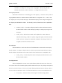
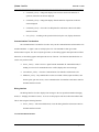
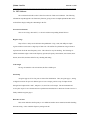
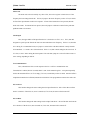
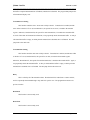
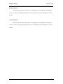
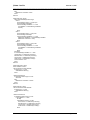
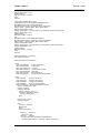
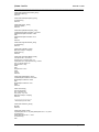
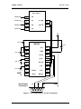
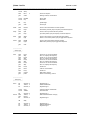
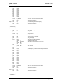
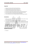
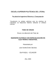
3b. PIC Subsystem Schematics
This section contains four schematics that display all the connections within the PIC subsystem.
The first details the PIC’s power and ground connections, the second lists connections that need to be made
to the PC and the transmitter subsystem, the third displays how the PIC is connected to the four 7447 BCD
decoders, and the final one shows how all the connections are made between the 7447’s and seven segment
displays (the same four all four sets).
+5
1 k?
1
PIC 16F877
+5
0.1 pf
0.1 pf
20 MHz
MCLR
+5
11
Vdd
Vdd
32
12
Vss
Vss
31
11
OSC1
11
OSC2
GND
GND
Figure 1. PIC Power and Ground Connections
Version 1
Service Manual
Page 36 of 63
@Home Radio
December 14, 2001
_____________________________________________________________________________
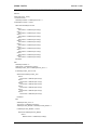
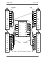
PIC 16F877
IC Pin 15
2
A0
IC Pin 15
3
A1
C7 / RX
26
IC Pin 15
4
A2
C6 / TX
25
IC Pin 15
5
A3
+5
0.1 ? F
0.1 ? F
0.1 ? F
0.1 ? F
GND
MAX232
0.1 ? F
1
Vcc
16
2
GND
15
3
T1 Out
14
4
R1 In
13
5
R1 Out
12
6
T1 In
11
7
T2 Out
T2 In
10
8
R2 In
R2 Out
9
Serial Cable
Connection
TX
RX
GND
GND
Figure 2. PIC Connections to PC and Transmitter
Version 1
Service Manual
Page 37 of 63
@Home Radio
December 14, 2001
_____________________________________________________________________________
+5
Hundreds
16
+5
Ones
+5
16
+5
Vcc
Vcc
1
1
C
2
2
C
LT
3
3
LT
BI
4
4
BI
RBI
5
5
RBI
D
6
6
D
A
7
GND
8
B
7447
PIC 16F877
GND
+5
16
+5
B
1
D7
30
7
A
D6
29
8
GND
D5
28
GND
D4
27
8
E0
9
E1
10
E2
19
D0
D3
22
20
D1
D2
21
Vcc
B
7447
+5
16
Vcc
1
B
C
2
2
C
LT
3
3
LT
BI
4
4
BI
RBI
5
5
RBI
D
6
6
D
A
7
7
A
GND
8
8
GND
7447
Version 1
GND
Tens
Decimals
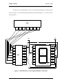
Figure 3. PIC to BCD Decoders Connections
Service Manual
GND
7447
Page 38 of 63
@Home Radio
December 14, 2001
_____________________________________________________________________________
All of the four seven segment display / resistor / 7447 BCD Decoder displays are exactly the same
with one exception – pin 9 on the ones display should be tied to ground through a 330 ? resistor to activate
the decimal point.
7447
9
10
11
12
13
14
15
+5
+5
c
b
a
1
14
2
13
2
3
12
3
11
4
a
1
14
13
f
4
330 ?
b
12
g
5
10
6
9
7
8
f
5
e
11
e
c
6
9
7
d
g
10
d
dec
8
Figure 4. BCD Decoder to Seven Segment Display Connections
Version 1
Service Manual
Page 39 of 63
@Home Radio
December 14, 2001
_____________________________________________________________________________
3c. PIC Subsystem Code
This code should be compiled using Microchip’s MPLAB software. It can be downloaded at
Microchip’s website – http://www.microchip.com/. The generated .hex file can be burned to the PIC using
the PICStartPlus software attached to MPLAB or with the EPIC PIC programming software –
http://www.melabs.com/products/epic.htm.
;------------------------;
; PIC Subsystem ;
;------------------------;
;-------------------------;
; Processor Decs ;
;-------------------------;
LIST
include
p=16f877
"c:\Progra~1\MPLAB\p16f877.INC"
;------------------------;
; Register Usage ;
;------------------------;
CBLOCK 0x00C
;Start registers at end of the values
;High byte of delay variable
Dlay
ENDC
freq
count
oldfrq
addr
equ
equ
equ
equ
0x020
0x021
0x022
0x030
;Holds frequency value
;Holds counter for delay
;Holds previous frequency value
;Holds eeprom data address – not currently used
#define
#define
#define
#define
#define
#define
#define
#define
Freq0
Freq1
Freq2
Freq3
Freq4
Freq5
Freq6
Freq7
freq,
freq,
freq,
freq,
freq,
freq,
freq,
freq,
#define
#define
DownB
UpB
PORTB, 0
PORTB, 1
#define
#define
SterB
MuteB
PORTB, 2
PORTB, 3
#define
#define
SterL
MuteL
PORTB, 6
PORTB, 7
0
1
2
3
4
5
6
7
;---------------------;
; Code Origin ;
;---------------------;
org
goto
Version 1
0
start
Service Manual
Page 40 of 63
@Home Radio
December 14, 2001
_____________________________________________________________________________
;--------------------;
; Port Setup ;
;--------------------;
start
bcf
bcf
STATUS, 5
STATUS, 6
;Register Page 0
clrf
clrf
clrf
clrf
clrf
PORTA
PORTB
PORTC
PORTD
PORTE
;Initialize data ports
bsf
bcf
STATUS, 5
STATUS, 6
;Register Page 1
movlw
movwf
0x06
ADCON1 ^
0x080
movlw
movwf
0x00
TRISA
0x080
movlw
movwf
movlw
movwf
0x3F
TRISB
^
0x7F
OPTION_REG
movlw
movwf
0xFE
TRISC
^
0x080
movlw
movwf
0x00
TRISD
^
0x080
movlw
movwf
0x00
TRISE
^
0x080
movlw
movwf
#081h
SPBRG
^
0x080
bcf
TXSTA,
4
bcf
bsf
bsf
STATUS, 5
RCSTA, 7
RCSTA, 4
goto
run1
;Disable A/D
;Port A Output
^
;PortB I/O, Pullups Enabled
0x080
^
;Enable pull-ups
0x080
;PortC Serial PC Communication
;PortD Output
;PortE Output
;Set baud rate to 2400
;Asynchronous
;Register Page 0
;Asynchronous
;Enable reception
;-------------------------;
;Run Once at Start ;
;-------------------------;
run1
;call
movlw
movwf
rdata
b'00000000'
freq
;Load previous frequency
bsf
bcf
SterL
MuteL
;Load previous stereo / mono setting
;Load previous mute setting
goto
trans
;Transmit previous frequency to PC
freq
;Save old frequency
;Store previous frequency
;---------------------;
; Main Code ;
;---------------------;
main
Version 1
movfw
Service Manual
Page 41 of 63
@Home Radio
December 14, 2001
_____________________________________________________________________________
movwf
oldfrq
btfss
goto
PIR1,
chkdn
movfw
movwf
RCREG
freq
;Get pc data
;Store data
tstf
freq
;Update flags
goto
chkin
;Check input
chkdn
btfss
goto
DownB
freqd
;Check to see if down button has been pressed
;Down button pressed, jump to frequency decrement sequence
chkup
btfss
goto
UpB
frequ
;Check to see if up button has been pressed
;Up button pressed, jump to frequency increment sequence
chkst
btfss
goto
SterB
togst
;Check to see if stereo / mono button has been pressed
;Stereo / mono button pressed, jump to toggle stereo sequence
chkmu
btfss
goto
MuteB
togmu
;Check to see if mute button has been pressed
;Mute button pressed, jump to toggle mute sequence
goto
main
5
;Check for reception
;Nothing recieved, check buttons
;---------------------;
; Check Input ;
;---------------------;
chkin
btfss
goto
btfss
goto
btfss
goto
btfss
goto
Freq7
dispf
Freq6
dispf
Freq5
dispf
Freq4
dispf
;Check for 1111 as the first nibble
;Not 1111, display new frequency
;Check for 1111 as the first nibble
;Not 1111, display new frequency
;Check for 1111 as the first nibble
;Not 1111, display new frequency
;Check for 1111 as the first nibble
;Not 1111, display new frequency
btfsc
goto
Freq2
tscom
;Check bit 2
;Test PC communication
btfsc
goto
goto
Freq1
pcmute
pcster
;Check bit 1
;Mute setting, check it
;Stereo / mono setting, check it
bsf
bsf
bcf
STATUS, 5
TXSTA, 5
STATUS, 5
;Register Page 1
;Enable transmission
;Register Page 0
movlw
movwf
0xF4
TXREG
;Load test value for transmission
;Send test value
bsf
btfss
goto
bcf
STATUS, 5
TXSTA, 1
tscom2
STATUS, 5
;Register Page 1
;Wait until transmit buffer is empty
call
delay
bsf
bcf
bcf
STATUS, 5
TXSTA, 5
STATUS, 5
;----------------------;
; Test Comm ;
;----------------------;
tscom
tscom2
Version 1
;Register Page 0
;Register Page 1
;Disable transmission
;Register Page 0
Service Manual
Page 42 of 63
@Home Radio
December 14, 2001
_____________________________________________________________________________
goto
main
;Restart loop
;-----------------------;
; PC Set Stereo ;
;-----------------------;
pcster
btfss
goto
Freq0
setmon
;Is it set to stereo or mono?
;Mono, turn off LED
setstr
bsf
goto
SterL
restf
;Stereo, turn on mono / stereo LED
;Restore frequency
setmon
bcf
goto
SterL
restf
;Turn off mono / stereo LED
;Restore frequency
;----------------------;
; PC Set Mute ;
;----------------------;
pcmute
btfss
goto
Freq0
setmun
;Is mute on or off??
;Mute, turn on LED
setmuf
bcf
goto
MuteL
restf
;Mute off, turn off LED
;Restore frequency
setmun
bsf
goto
MuteL
restf
;Turn on mute LED
;Restore frequency
oldfrq
freq
main
;Load old frequency
;Restore since it was not actually changed
;Restart loop
btfss
goto
DownB
$-1
;Is the down button still pressed?
;Yes, go back
movlw
movwf
movlw
0x00C
Dlay
0x0D7
;Wait for debounce
;Delay 20 msecs
btfss
goto
DownB
$-6
;Is the down button still pressed?
;Yes, go back again
ifndef
Debug
addlw
btfsc
decfsz
goto
1
STATUS, Z
Dlay
$-5
decfsz
goto
Dlay
$-3
;----------------------;
; Restore Freq ;
;----------------------;
restf
movfw
movwf
goto
;------------------------;
; Decrement Freq ;
;------------------------;
freqd
;Skip small loop if Debug is defined
;Increment the delay count
;If low byte in w is not equal to zero, then loop
else
;Else, short loop
endif
btfsc
goto
btfsc
goto
btfsc
goto
Version 1
Freq0
freqd2
Freq1
freqd2
Freq2
freqd2
;Check frequency to ensure it is not already at min value
Service Manual
Page 43 of 63
@Home Radio
December 14, 2001
_____________________________________________________________________________
freqd2
btfsc
goto
btfsc
goto
btfsc
goto
btfsc
goto
btfsc
goto
Freq3
freqd2
Freq4
freqd2
Freq5
freqd2
Freq6
freqd2
Freq7
freqd2
movlw
movwf
goto
b'11001000'
freq
trans
;Min value, wrap back around to max value
decf
goto
freq
trans
;Done debouncing, decrement frequency
;Transmit new frequency
btfss
goto
UpB
$-1
;Is the up button still pressed?
;Yes, go back
movlw
movwf
movlw
0x00C
Dlay
0x0D7
;Wait for debounce
;Delay 20 msecs
btfss
goto
UpB
$-6
;Is the up button still pressed?
;Yes, go back again
ifndef
Debug
addlw
btfsc
decfsz
goto
1
STATUS, Z
Dlay
$-5
decfsz
goto
Dlay
$-3
;Transmit new frequency
;-----------------------;
; Increment Freq ;
;-----------------------;
frequ
;Skip small loop if Debug is defined
;Increment the delay count
;If low byte in w is not equal to zero, then loop
else
;Else, short loop
endif
frequ2
btfsc
goto
btfsc
goto
btfsc
goto
btfss
goto
btfsc
goto
btfsc
goto
btfss
goto
btfss
goto
Freq0
frequ2
Freq1
frequ2
Freq2
frequ2
Freq3
frequ2
Freq4
frequ2
Freq5
frequ2
Freq6
frequ2
Freq7
frequ2
;Check frequency to ensure it is not already at min value
movlw
movwf
goto
b'00000000'
freq
trans
;Max value, wrap back around to min value
incf
goto
freq
trans
;Transmit new frequency
;Transmit new frequency
;-----------------------;
; Toggle Stereo ;
Version 1
Service Manual
Page 44 of 63
@Home Radio
December 14, 2001
_____________________________________________________________________________
;-----------------------;
togst
btfss
goto
SterB
$-1
;Is the stereo / mono button still pressed?
;Yes, go back
movlw
movwf
movlw
0x00C
Dlay
0x0D7
;Wait for debounce
;Delay 20 msecs
btfss
goto
SterB
$-6
;Is the stereo / mono button still pressed?
;Yes, go back again
ifndef
Debug
addlw
btfsc
decfsz
goto
1
STATUS, Z
Dlay
$-5
decfsz
goto
Dlay
$-3
;Skip small loop if Debug is defined
;Increment the delay count
;If low byte in w is not equal to zero, then loop
else
;Else, short loop
endif
btfss
goto
SterL
ston
;Is stereo already selected?
;No, change from mono to stereo
stoff
bcf
goto
SterL
txst
;Yes, turn stereo LED off
ston
bsf
goto
SterL
txst
;Turn stereo LED on
btfss
goto
MuteB
$-1
;Is the stereo / mono button still pressed?
;Yes, go back
movlw
movwf
movlw
0x00C
Dlay
0x0D7
;Wait for debounce
;Delay 20 msecs
btfss
goto
MuteB
$-6
;Is the stereo / mono button still pressed?
;Yes, go back again
ifndef
Debug
addlw
btfsc
decfsz
goto
1
STATUS, Z
Dlay
$-5
decfsz
goto
Dlay
$-3
;----------------------;
; Toggle Mute ;
;----------------------;
togmu
;Skip small loop if Debug is defined
;Increment the delay count
;If low byte in w is not equal to zero, then loop
else
;Else, short loop
endif
btfss
goto
MuteL
muton
;Is mute already selected?
;No, mute transmission
mutoff
bcf
goto
MuteL
txmut
;Yes, turn mute LED off
muton
bsf
goto
MuteL
txmut
;Turn mute LED on
Version 1
Service Manual
Page 45 of 63
@Home Radio
December 14, 2001
_____________________________________________________________________________
;---------------------;
; Display Freq ;
;---------------------;
dispf
movlw
movwf
movfw
HIGH
decone
PCLATH
freq
;Set counter to correct table address
call
movwf
decone
PORTD
;Call table for decimals and ones display
;Display decimals and ones values
movlw
movwf
movfw
HIGH
tenhun
PCLATH
freq
;Set counter to correct table address
call
movwf
tenhun
PORTE
;Call table for tens and hundreds display
;call
wdata
;Store frequency in eeprom – not used
goto
main
;Transmit new frequency to PC
bsf
bsf
bcf
STATUS, 5
TXSTA, 5
STATUS, 5
;Register Page 1
;Enable transmission
;Register Page 0
movfw
movwf
freq
TXREG
;Load frequency for transmission
;Send the frequency
bsf
btfss
goto
bcf
STATUS, 5
TXSTA, 1
trans2
STATUS, 5
;Register Page 1
;Wait until transmit buffer is empty
call
delay
bsf
bcf
bcf
STATUS, 5
TXSTA, 5
STATUS, 5
goto
dispf
;----------------------;
; Transmit Freq ;
;----------------------;
trans
trans2
;Register Page 0
;Register Page 1
;Disable transmission
;Register Page 0
;-----------------------;
; Transmit Stereo ;
;-----------------------;
txst
bsf
bsf
bcf
STATUS, 5
TXSTA, 5
STATUS, 5
;Register Page 1
;Enable transmission
;Register Page 0
btfss
goto
SterL
txst2
;Is stereo on?
txst1
movlw
goto
0xF1
txst3
;Yes, send F1
txst2
movlw
0xF0
;No, send F0
txst3
movwf
TXREG
;Send the state
bsf
btfss
goto
bcf
STATUS, 5
TXSTA, 1
txst4
STATUS, 5
;Register Page 1
;Wait until transmit buffer is empty
txst4
Version 1
;Register Page 0
Service Manual
Page 46 of 63
@Home Radio
December 14, 2001
_____________________________________________________________________________
call
delay
bsf
bcf
bcf
STATUS, 5
TXSTA, 5
STATUS, 5
goto
main
;Register Page 1
;Disable transmission
;Register Page 0
;----------------------;
; Transmit Mute ;
;----------------------;
txmut
bsf
bsf
bcf
STATUS, 5
TXSTA, 5
STATUS, 5
;Register Page 1
;Enable transmission
;Register Page 0
btfss
goto
MuteL
txmut2
;Is mute on?
txmut1
movlw
goto
0xF2
txmut3
;Yes, send F2
txmut2
movlw
0xF3
;No, send F3
txmut3
movwf
TXREG
;Send the state
bsf
btfss
goto
bcf
STATUS, 5
TXSTA, 1
txmut4
STATUS, 5
;Register Page 1
;Wait until transmit buffer is empty
call
delay
bsf
bcf
bcf
STATUS, 5
TXSTA, 5
STATUS, 5
goto
main
txmut4
;Register Page 0
;Register Page 1
;Disable transmission
;Register Page 0
;------------------;
;
Delay
;
;------------------;
delay
movlw
movwf
#0FFh
count
delay2
decfsz
goto
count
delay2
return
;---------------------;
; Data Read ;
;---------------------;
;This feature is not currently in use
rdata
Version 1
bsf
bcf
STATUS, RP1
STATUS, RP0
;Register page 2
movf
movwf
addr,
EEADR
;Write address to read from
bsf
STATUS, RP0
;Register page 3
bcf
EECON1, EEPGD
;Point to data memory
w
Service Manual
Page 47 of 63
@Home Radio
December 14, 2001
_____________________________________________________________________________
bsf
EECON1, RD
;Start read operation
bcf
STATUS, RP0
;Register page 2
movf
movwf
EEDATA, w
freq
;Read in data
;Store frequency data
bcf
bcf
STATUS, 5
STATUS, 6
;Register page 0
return
;Return to previous position in code
;--------------------;
; Data Write ;
;--------------------;
;This feature is not currently in use
wdata
bsf
bsf
STATUS, RP1
STATUS, RP0
;Register page 3
btfsc
goto
EECON1, WR
$-1
;Wait for write to finish
bcf
STATUS, RP0
;Register page 2
movf
movwf
addr,
EEADR
;Address to write to
movf
movwf
freq,
w
EEDATA
;Load frequency data to write
bsf
STATUS, RP0
;Register page 3
bcf
bsf
EECON1, EEPGD
EECON1, WREN
;Point to data memory
;Enable writes
movlw
movwf
0x55
EECON2
;Write 55h to EECON2
movlw
movwf
0xAA
EECON2
;Write AAh to EECON2
bsf
bcf
EECON1, WR
EECON1, WREN
;Start write operation
;Disable writes
bcf
bcf
STATUS, 5
STATUS, 6
;Register page 0
w
return
;------------------------;
; Dec's and Ones ;
;------------------------;
decone
Version 1
org
0x300
addwf
retlw
retlw
retlw
retlw
retlw
retlw
retlw
retlw
retlw
retlw
PCL,
F
b'01111001'
b'10000000'
b'10000001'
b'10000010'
b'10000011'
b'10000100'
b'10000101'
b'10000110'
b'10000111'
b'10001000'
;Ones = 7, Decimals = 9
;Ones = 8, Decimals = 0
;Ones = 8, Decimals = 1
;Ones = 8, Decimals = 2
;Ones = 8, Decimals = 3
;Ones = 8, Decimals = 4
;Ones = 8, Decimals = 5
;Ones = 8, Decimals = 6
;Ones = 8, Decimals = 7
;Ones = 8, Decimals = 8
Service Manual
Page 48 of 63
@Home Radio
December 14, 2001
_____________________________________________________________________________
retlw
retlw
retlw
retlw
retlw
retlw
retlw
retlw
retlw
retlw
retlw
retlw
retlw
retlw
retlw
retlw
retlw
retlw
retlw
retlw
retlw
retlw
retlw
retlw
retlw
retlw
retlw
retlw
retlw
retlw
retlw
retlw
retlw
retlw
retlw
retlw
retlw
retlw
retlw
retlw
retlw
retlw
retlw
retlw
retlw
retlw
retlw
retlw
retlw
retlw
retlw
retlw
retlw
retlw
retlw
retlw
retlw
retlw
retlw
retlw
retlw
retlw
retlw
retlw
retlw
retlw
retlw
retlw
retlw
retlw
Version 1
b'10001001'
b'10010000'
b'10010001'
b'10010010'
b'10010011'
b'10010100'
b'10010101'
b'10010110'
b'10010111'
b'10011000'
b'10011001'
b'00000000'
b'00000001'
b'00000010'
b'00000011'
b'00000100'
b'00000101'
b'00000110'
b'00000111'
b'00001000'
b'00001001'
b'00010000'
b'00010001'
b'00010010'
b'00010011'
b'00010100'
b'00010101'
b'00010110'
b'00010111'
b'00011000'
b'00011001'
b'00100000'
b'00100001'
b'00100010'
b'00100011'
b'00100100'
b'00100101'
b'00100110'
b'00100111'
b'00101000'
b'00101001'
b'00110000'
b'00110001'
b'00110010'
b'00110011'
b'00110100'
b'00110101'
b'00110110'
b'00110111'
b'00111000'
b'00111001'
b'01000000'
b'01000001'
b'01000010'
b'01000011'
b'01000100'
b'01000101'
b'01000110'
b'01000111'
b'01001000'
b'01001001'
b'01010000'
b'01010001'
b'01010010'
b'01010011'
b'01010100'
b'01010101'
b'01010110'
b'01010111'
b'01011000'
;Ones = 8, Decimals = 9
;Ones = 9, Decimals = 0
;Ones = 9, Decimals = 1
;Ones = 9, Decimals = 2
;Ones = 9, Decimals = 3
;Ones = 9, Decimals = 4
;Ones = 9, Decimals = 5
;Ones = 9, Decimals = 6
;Ones = 9, Decimals = 7
;Ones = 9, Decimals = 8
;Ones = 9, Decimals = 9
;Ones = 0, Decimals = 0
;Ones = 0, Decimals = 1
;Ones = 0, Decimals = 2
;Ones = 0, Decimals = 3
;Ones = 0, Decimals = 4
;Ones = 0, Decimals = 5
;Ones = 0, Decimals = 6
;Ones = 0, Decimals = 7
;Ones = 0, Decimals = 8
;Ones = 0, Decimals = 9
;Ones = 1, Decimals = 0
;Ones = 1, Decimals = 1
;Ones = 1, Decimals = 2
;Ones = 1, Decimals = 3
;Ones = 1, Decimals = 4
;Ones = 1, Decimals = 5
;Ones = 1, Decimals = 6
;Ones = 1, Decimals = 7
;Ones = 1, Decimals = 8
;Ones = 1, Decimals = 9
;Ones = 2, Decimals = 0
;Ones = 2, Decimals = 1
;Ones = 2, Decimals = 2
;Ones = 2, Decimals = 3
;Ones = 2, Decimals = 4
;Ones = 2, Decimals = 5
;Ones = 2, Decimals = 6
;Ones = 2, Decimals = 7
;Ones = 2, Decimals = 8
;Ones = 2, Decimals = 9
;Ones = 3, Decimals = 0
;Ones = 3, Decimals = 1
;Ones = 3, Decimals = 2
;Ones = 3, Decimals = 3
;Ones = 3, Decimals = 4
;Ones = 3, Decimals = 5
;Ones = 3, Decimals = 6
;Ones = 3, Decimals = 7
;Ones = 3, Decimals = 8
;Ones = 3, Decimals = 9
;Ones = 4, Decimals = 0
;Ones = 4, Decimals = 1
;Ones = 4, Decimals = 2
;Ones = 4, Decimals = 3
;Ones = 4, Decimals = 4
;Ones = 4, Decimals = 5
;Ones = 4, Decimals = 6
;Ones = 4, Decimals = 7
;Ones = 4, Decimals = 8
;Ones = 4, Decimals = 9
;Ones = 5, Decimals = 0
;Ones = 5, Decimals = 1
;Ones = 5, Decimals = 2
;Ones = 5, Decimals = 3
;Ones = 5, Decimals = 4
;Ones = 5, Decimals = 5
;Ones = 5, Decimals = 6
;Ones = 5, Decimals = 7
;Ones = 5, Decimals = 8
Service Manual
Page 49 of 63
@Home Radio
December 14, 2001
_____________________________________________________________________________
retlw
retlw
retlw
retlw
retlw
retlw
retlw
retlw
retlw
retlw
retlw
retlw
retlw
retlw
retlw
retlw
retlw
retlw
retlw
retlw
retlw
retlw
retlw
retlw
retlw
retlw
retlw
retlw
retlw
retlw
retlw
retlw
retlw
retlw
retlw
retlw
retlw
retlw
retlw
retlw
retlw
retlw
retlw
retlw
retlw
retlw
retlw
retlw
retlw
retlw
retlw
retlw
retlw
retlw
retlw
retlw
retlw
retlw
retlw
retlw
retlw
retlw
retlw
retlw
retlw
retlw
retlw
retlw
retlw
retlw
Version 1
b'01011001'
b'01100000'
b'01100001'
b'01100010'
b'01100011'
b'01100100'
b'01100101'
b'01100110'
b'01100111'
b'01101000'
b'01101001'
b'01110000'
b'01110001'
b'01110010'
b'01110011'
b'01110100'
b'01110101'
b'01110110'
b'01110111'
b'01111000'
b'01111001'
b'10000000'
b'10000001'
b'10000010'
b'10000011'
b'10000100'
b'10000101'
b'10000110'
b'10000111'
b'10001000'
b'10001001'
b'10010000'
b'10010001'
b'10010010'
b'10010011'
b'10010100'
b'10010101'
b'10010110'
b'10010111'
b'10011000'
b'10011001'
b'00000000'
b'00000001'
b'00000010'
b'00000011'
b'00000100'
b'00000101'
b'00000110'
b'00000111'
b'00001000'
b'00001001'
b'00010000'
b'00010001'
b'00010010'
b'00010011'
b'00010100'
b'00010101'
b'00010110'
b'00010111'
b'00011000'
b'00011001'
b'00100000'
b'00100001'
b'00100010'
b'00100011'
b'00100100'
b'00100101'
b'00100110'
b'00100111'
b'00101000'
;Ones = 5, Decimals = 9
;Ones = 6, Decimals = 0
;Ones = 6, Decimals = 1
;Ones = 6, Decimals = 2
;Ones = 6, Decimals = 3
;Ones = 6, Decimals = 4
;Ones = 6, Decimals = 5
;Ones = 6, Decimals = 6
;Ones = 6, Decimals = 7
;Ones = 6, Decimals = 8
;Ones = 6, Decimals = 9
;Ones = 7, Decimals = 0
;Ones = 7, Decimals = 1
;Ones = 7, Decimals = 2
;Ones = 7, Decimals = 3
;Ones = 7, Decimals = 4
;Ones = 7, Decimals = 5
;Ones = 7, Decimals = 6
;Ones = 7, Decimals = 7
;Ones = 7, Decimals = 8
;Ones = 7, Decimals = 9
;Ones = 8, Decimals = 0
;Ones = 8, Decimals = 1
;Ones = 8, Decimals = 2
;Ones = 8, Decimals = 3
;Ones = 8, Decimals = 4
;Ones = 8, Decimals = 5
;Ones = 8, Decimals = 6
;Ones = 8, Decimals = 7
;Ones = 8, Decimals = 8
;Ones = 8, Decimals = 9
;Ones = 9, Decimals = 0
;Ones = 9, Decimals = 1
;Ones = 9, Decimals = 2
;Ones = 9, Decimals = 3
;Ones = 9, Decimals = 4
;Ones = 9, Decimals = 5
;Ones = 9, Decimals = 6
;Ones = 9, Decimals = 7
;Ones = 9, Decimals = 8
;Ones = 9, Decimals = 9
;Ones = 0, Decimals = 0
;Ones = 0, Decimals = 1
;Ones = 0, Decimals = 2
;Ones = 0, Decimals = 3
;Ones = 0, Decimals = 4
;Ones = 0, Decimals = 5
;Ones = 0, Decimals = 6
;Ones = 0, Decimals = 7
;Ones = 0, Decimals = 8
;Ones = 0, Decimals = 9
;Ones = 1, Decimals = 0
;Ones = 1, Decimals = 1
;Ones = 1, Decimals = 2
;Ones = 1, Decimals = 3
;Ones = 1, Decimals = 4
;Ones = 1, Decimals = 5
;Ones = 1, Decimals = 6
;Ones = 1, Decimals = 7
;Ones = 1, Decimals = 8
;Ones = 1, Decimals = 9
;Ones = 2, Decimals = 0
;Ones = 2, Decimals = 1
;Ones = 2, Decimals = 2
;Ones = 2, Decimals = 3
;Ones = 2, Decimals = 4
;Ones = 2, Decimals = 5
;Ones = 2, Decimals = 6
;Ones = 2, Decimals = 7
;Ones = 2, Decimals = 8
Service Manual
Page 50 of 63
@Home Radio
December 14, 2001
_____________________________________________________________________________
retlw
retlw
retlw
retlw
retlw
retlw
retlw
retlw
retlw
retlw
retlw
retlw
retlw
retlw
retlw
retlw
retlw
retlw
retlw
retlw
retlw
retlw
retlw
retlw
retlw
retlw
retlw
retlw
retlw
retlw
retlw
retlw
retlw
retlw
retlw
retlw
retlw
retlw
retlw
retlw
retlw
retlw
retlw
retlw
retlw
retlw
retlw
retlw
retlw
retlw
retlw
b'00101001'
b'00110000'
b'00110001'
b'00110010'
b'00110011'
b'00110100'
b'00110101'
b'00110110'
b'00110111'
b'00111000'
b'00111001'
b'01000000'
b'01000001'
b'01000010'
b'01000011'
b'01000100'
b'01000101'
b'01000110'
b'01000111'
b'01001000'
b'01001001'
b'01010000'
b'01010001'
b'01010010'
b'01010011'
b'01010100'
b'01010101'
b'01010110'
b'01010111'
b'01011000'
b'01011001'
b'01100000'
b'01100001'
b'01100010'
b'01100011'
b'01100100'
b'01100101'
b'01100110'
b'01100111'
b'01101000'
b'01101001'
b'01110000'
b'01110001'
b'01110010'
b'01110011'
b'01110100'
b'01110101'
b'01110110'
b'01110111'
b'01111000'
b'01111001'
;Ones = 2, Decimals = 9
;Ones = 3, Decimals = 0
;Ones = 3, Decimals = 1
;Ones = 3, Decimals = 2
;Ones = 3, Decimals = 3
;Ones = 3, Decimals = 4
;Ones = 3, Decimals = 5
;Ones = 3, Decimals = 6
;Ones = 3, Decimals = 7
;Ones = 3, Decimals = 8
;Ones = 3, Decimals = 9
;Ones = 4, Decimals = 0
;Ones = 4, Decimals = 1
;Ones = 4, Decimals = 2
;Ones = 4, Decimals = 3
;Ones = 4, Decimals = 4
;Ones = 4, Decimals = 5
;Ones = 4, Decimals = 6
;Ones = 4, Decimals = 7
;Ones = 4, Decimals = 8
;Ones = 4, Decimals = 9
;Ones = 5, Decimals = 0
;Ones = 5, Decimals = 1
;Ones = 5, Decimals = 2
;Ones = 5, Decimals = 3
;Ones = 5, Decimals = 4
;Ones = 5, Decimals = 5
;Ones = 5, Decimals = 6
;Ones = 5, Decimals = 7
;Ones = 5, Decimals = 8
;Ones = 5, Decimals = 9
;Ones = 6, Decimals = 0
;Ones = 6, Decimals = 1
;Ones = 6, Decimals = 2
;Ones = 6, Decimals = 3
;Ones = 6, Decimals = 4
;Ones = 6, Decimals = 5
;Ones = 6, Decimals = 6
;Ones = 6, Decimals = 7
;Ones = 6, Decimals = 8
;Ones = 6, Decimals = 9
;Ones = 7, Decimals = 0
;Ones = 7, Decimals = 1
;Ones = 7, Decimals = 2
;Ones = 7, Decimals = 3
;Ones = 7, Decimals = 4
;Ones = 7, Decimals = 5
;Ones = 7, Decimals = 6
;Ones = 7, Decimals = 7
;Ones = 7, Decimals = 8
;Ones = 7, Decimals = 9
;-------------------------;
; Tens and Hund's ;
;-------------------------;
tenhun
Version 1
org
0x0600
addwf
retlw
retlw
retlw
retlw
retlw
retlw
retlw
retlw
retlw
retlw
PCL,
F
b'00000010'
b'00000010'
b'00000010'
b'00000010'
b'00000010'
b'00000010'
b'00000010'
b'00000010'
b'00000010'
b'00000010'
;Hundreds = 0, Tens = 8
;Hundreds = 0, Tens = 8
;Hundreds = 0, Tens = 8
;Hundreds = 0, Tens = 8
;Hundreds = 0, Tens = 8
;Hundreds = 0, Tens = 8
;Hundreds = 0, Tens = 8
;Hundreds = 0, Tens = 8
;Hundreds = 0, Tens = 8
;Hundreds = 0, Tens = 8
Service Manual
Page 51 of 63
@Home Radio
December 14, 2001
_____________________________________________________________________________
retlw
retlw
retlw
retlw
retlw
retlw
retlw
retlw
retlw
retlw
retlw
retlw
retlw
retlw
retlw
retlw
retlw
retlw
retlw
retlw
retlw
retlw
retlw
retlw
retlw
retlw
retlw
retlw
retlw
retlw
retlw
retlw
retlw
retlw
retlw
retlw
retlw
retlw
retlw
retlw
retlw
retlw
retlw
retlw
retlw
retlw
retlw
retlw
retlw
retlw
retlw
retlw
retlw
retlw
retlw
retlw
retlw
retlw
retlw
retlw
retlw
retlw
retlw
retlw
retlw
retlw
retlw
retlw
retlw
retlw
Version 1
b'00000010'
b'00000010'
b'00000010'
b'00000010'
b'00000010'
b'00000010'
b'00000010'
b'00000010'
b'00000010'
b'00000010'
b'00000010'
b'00000011'
b'00000011'
b'00000011'
b'00000011'
b'00000011'
b'00000011'
b'00000011'
b'00000011'
b'00000011'
b'00000011'
b'00000011'
b'00000011'
b'00000011'
b'00000011'
b'00000011'
b'00000011'
b'00000011'
b'00000011'
b'00000011'
b'00000011'
b'00000011'
b'00000011'
b'00000011'
b'00000011'
b'00000011'
b'00000011'
b'00000011'
b'00000011'
b'00000011'
b'00000011'
b'00000011'
b'00000011'
b'00000011'
b'00000011'
b'00000011'
b'00000011'
b'00000011'
b'00000011'
b'00000011'
b'00000011'
b'00000011'
b'00000011'
b'00000011'
b'00000011'
b'00000011'
b'00000011'
b'00000011'
b'00000011'
b'00000011'
b'00000011'
b'00000011'
b'00000011'
b'00000011'
b'00000011'
b'00000011'
b'00000011'
b'00000011'
b'00000011'
b'00000011'
;Hundreds = 0, Tens = 8
;Hundreds = 0, Tens = 8
;Hundreds = 0, Tens = 8
;Hundreds = 0, Tens = 8
;Hundreds = 0, Tens = 8
;Hundreds = 0, Tens = 8
;Hundreds = 0, Tens = 8
;Hundreds = 0, Tens = 8
;Hundreds = 0, Tens = 8
;Hundreds = 0, Tens = 8
;Hundreds = 0, Tens = 8
;Hundreds = 0, Tens = 9
;Hundreds = 0, Tens = 9
;Hundreds = 0, Tens = 9
;Hundreds = 0, Tens = 9
;Hundreds = 0, Tens = 9
;Hundreds = 0, Tens = 9
;Hundreds = 0, Tens = 9
;Hundreds = 0, Tens = 9
;Hundreds = 0, Tens = 9
;Hundreds = 0, Tens = 9
;Hundreds = 0, Tens = 9
;Hundreds = 0, Tens = 9
;Hundreds = 0, Tens = 9
;Hundreds = 0, Tens = 9
;Hundreds = 0, Tens = 9
;Hundreds = 0, Tens = 9
;Hundreds = 0, Tens = 9
;Hundreds = 0, Tens = 9
;Hundreds = 0, Tens = 9
;Hundreds = 0, Tens = 9
;Hundreds = 0, Tens = 9
;Hundreds = 0, Tens = 9
;Hundreds = 0, Tens = 9
;Hundreds = 0, Tens = 9
;Hundreds = 0, Tens = 9
;Hundreds = 0, Tens = 9
;Hundreds = 0, Tens = 9
;Hundreds = 0, Tens = 9
;Hundreds = 0, Tens = 9
;Hundreds = 0, Tens = 9
;Hundreds = 0, Tens = 9
;Hundreds = 0, Tens = 9
;Hundreds = 0, Tens = 9
;Hundreds = 0, Tens = 9
;Hundreds = 0, Tens = 9
;Hundreds = 0, Tens = 9
;Hundreds = 0, Tens = 9
;Hundreds = 0, Tens = 9
;Hundreds = 0, Tens = 9
;Hundreds = 0, Tens = 9
;Hundreds = 0, Tens = 9
;Hundreds = 0, Tens = 9
;Hundreds = 0, Tens = 9
;Hundreds = 0, Tens = 9
;Hundreds = 0, Tens = 9
;Hundreds = 0, Tens = 9
;Hundreds = 0, Tens = 9
;Hundreds = 0, Tens = 9
;Hundreds = 0, Tens = 9
;Hundreds = 0, Tens = 9
;Hundreds = 0, Tens = 9
;Hundreds = 0, Tens = 9
;Hundreds = 0, Tens = 9
;Hundreds = 0, Tens = 9
;Hundreds = 0, Tens = 9
;Hundreds = 0, Tens = 9
;Hundreds = 0, Tens = 9
;Hundreds = 0, Tens = 9
;Hundreds = 0, Tens = 9
Service Manual
Page 52 of 63
@Home Radio
December 14, 2001
_____________________________________________________________________________
retlw
retlw
retlw
retlw
retlw
retlw
retlw
retlw
retlw
retlw
retlw
retlw
retlw
retlw
retlw
retlw
retlw
retlw
retlw
retlw
retlw
retlw
retlw
retlw
retlw
retlw
retlw
retlw
retlw
retlw
retlw
retlw
retlw
retlw
retlw
retlw
retlw
retlw
retlw
retlw
retlw
retlw
retlw
retlw
retlw
retlw
retlw
retlw
retlw
retlw
retlw
retlw
retlw
retlw
retlw
retlw
retlw
retlw
retlw
retlw
retlw
retlw
retlw
retlw
retlw
retlw
retlw
retlw
retlw
retlw
Version 1
b'00000011'
b'00000011'
b'00000011'
b'00000011'
b'00000011'
b'00000011'
b'00000011'
b'00000011'
b'00000011'
b'00000011'
b'00000011'
b'00000011'
b'00000011'
b'00000011'
b'00000011'
b'00000011'
b'00000011'
b'00000011'
b'00000011'
b'00000011'
b'00000011'
b'00000011'
b'00000011'
b'00000011'
b'00000011'
b'00000011'
b'00000011'
b'00000011'
b'00000011'
b'00000011'
b'00000011'
b'00000011'
b'00000011'
b'00000011'
b'00000011'
b'00000011'
b'00000011'
b'00000011'
b'00000011'
b'00000011'
b'00000011'
b'00000100'
b'00000100'
b'00000100'
b'00000100'
b'00000100'
b'00000100'
b'00000100'
b'00000100'
b'00000100'
b'00000100'
b'00000100'
b'00000100'
b'00000100'
b'00000100'
b'00000100'
b'00000100'
b'00000100'
b'00000100'
b'00000100'
b'00000100'
b'00000100'
b'00000100'
b'00000100'
b'00000100'
b'00000100'
b'00000100'
b'00000100'
b'00000100'
b'00000100'
;Hundreds = 0, Tens = 9
;Hundreds = 0, Tens = 9
;Hundreds = 0, Tens = 9
;Hundreds = 0, Tens = 9
;Hundreds = 0, Tens = 9
;Hundreds = 0, Tens = 9
;Hundreds = 0, Tens = 9
;Hundreds = 0, Tens = 9
;Hundreds = 0, Tens = 9
;Hundreds = 0, Tens = 9
;Hundreds = 0, Tens = 9
;Hundreds = 0, Tens = 9
;Hundreds = 0, Tens = 9
;Hundreds = 0, Tens = 9
;Hundreds = 0, Tens = 9
;Hundreds = 0, Tens = 9
;Hundreds = 0, Tens = 9
;Hundreds = 0, Tens = 9
;Hundreds = 0, Tens = 9
;Hundreds = 0, Tens = 9
;Hundreds = 0, Tens = 9
;Hundreds = 0, Tens = 9
;Hundreds = 0, Tens = 9
;Hundreds = 0, Tens = 9
;Hundreds = 0, Tens = 9
;Hundreds = 0, Tens = 9
;Hundreds = 0, Tens = 9
;Hundreds = 0, Tens = 9
;Hundreds = 0, Tens = 9
;Hundreds = 0, Tens = 9
;Hundreds = 0, Tens = 9
;Hundreds = 0, Tens = 9
;Hundreds = 0, Tens = 9
;Hundreds = 0, Tens = 9
;Hundreds = 0, Tens = 9
;Hundreds = 0, Tens = 9
;Hundreds = 0, Tens = 9
;Hundreds = 0, Tens = 9
;Hundreds = 0, Tens = 9
;Hundreds = 0, Tens = 9
;Hundreds = 0, Tens = 9
;Hundreds = 1, Tens = 0
;Hundreds = 1, Tens = 0
;Hundreds = 1, Tens = 0
;Hundreds = 1, Tens = 0
;Hundreds = 1, Tens = 0
;Hundreds = 1, Tens = 0
;Hundreds = 1, Tens = 0
;Hundreds = 1, Tens = 0
;Hundreds = 1, Tens = 0
;Hundreds = 1, Tens = 0
;Hundreds = 1, Tens = 0
;Hundreds = 1, Tens = 0
;Hundreds = 1, Tens = 0
;Hundreds = 1, Tens = 0
;Hundreds = 1, Tens = 0
;Hundreds = 1, Tens = 0
;Hundreds = 1, Tens = 0
;Hundreds = 1, Tens = 0
;Hundreds = 1, Tens = 0
;Hundreds = 1, Tens = 0
;Hundreds = 1, Tens = 0
;Hundreds = 1, Tens = 0
;Hundreds = 1, Tens = 0
;Hundreds = 1, Tens = 0
;Hundreds = 1, Tens = 0
;Hundreds = 1, Tens = 0
;Hundreds = 1, Tens = 0
;Hundreds = 1, Tens = 0
;Hundreds = 1, Tens = 0
Service Manual
Page 53 of 63
@Home Radio
December 14, 2001
_____________________________________________________________________________
retlw
retlw
retlw
retlw
retlw
retlw
retlw
retlw
retlw
retlw
retlw
retlw
retlw
retlw
retlw
retlw
retlw
retlw
retlw
retlw
retlw
retlw
retlw
retlw
retlw
retlw
retlw
retlw
retlw
retlw
retlw
retlw
retlw
retlw
retlw
retlw
retlw
retlw
retlw
retlw
retlw
retlw
retlw
retlw
retlw
retlw
retlw
retlw
retlw
retlw
retlw
b'00000100'
b'00000100'
b'00000100'
b'00000100'
b'00000100'
b'00000100'
b'00000100'
b'00000100'
b'00000100'
b'00000100'
b'00000100'
b'00000100'
b'00000100'
b'00000100'
b'00000100'
b'00000100'
b'00000100'
b'00000100'
b'00000100'
b'00000100'
b'00000100'
b'00000100'
b'00000100'
b'00000100'
b'00000100'
b'00000100'
b'00000100'
b'00000100'
b'00000100'
b'00000100'
b'00000100'
b'00000100'
b'00000100'
b'00000100'
b'00000100'
b'00000100'
b'00000100'
b'00000100'
b'00000100'
b'00000100'
b'00000100'
b'00000100'
b'00000100'
b'00000100'
b'00000100'
b'00000100'
b'00000100'
b'00000100'
b'00000100'
b'00000100'
b'00000100'
;Hundreds = 1, Tens = 0
;Hundreds = 1, Tens = 0
;Hundreds = 1, Tens = 0
;Hundreds = 1, Tens = 0
;Hundreds = 1, Tens = 0
;Hundreds = 1, Tens = 0
;Hundreds = 1, Tens = 0
;Hundreds = 1, Tens = 0
;Hundreds = 1, Tens = 0
;Hundreds = 1, Tens = 0
;Hundreds = 1, Tens = 0
;Hundreds = 1, Tens = 0
;Hundreds = 1, Tens = 0
;Hundreds = 1, Tens = 0
;Hundreds = 1, Tens = 0
;Hundreds = 1, Tens = 0
;Hundreds = 1, Tens = 0
;Hundreds = 1, Tens = 0
;Hundreds = 1, Tens = 0
;Hundreds = 1, Tens = 0
;Hundreds = 1, Tens = 0
;Hundreds = 1, Tens = 0
;Hundreds = 1, Tens = 0
;Hundreds = 1, Tens = 0
;Hundreds = 1, Tens = 0
;Hundreds = 1, Tens = 0
;Hundreds = 1, Tens = 0
;Hundreds = 1, Tens = 0
;Hundreds = 1, Tens = 0
;Hundreds = 1, Tens = 0
;Hundreds = 1, Tens = 0
;Hundreds = 1, Tens = 0
;Hundreds = 1, Tens = 0
;Hundreds = 1, Tens = 0
;Hundreds = 1, Tens = 0
;Hundreds = 1, Tens = 0
;Hundreds = 1, Tens = 0
;Hundreds = 1, Tens = 0
;Hundreds = 1, Tens = 0
;Hundreds = 1, Tens = 0
;Hundreds = 1, Tens = 0
;Hundreds = 1, Tens = 0
;Hundreds = 1, Tens = 0
;Hundreds = 1, Tens = 0
;Hundreds = 1, Tens = 0
;Hundreds = 1, Tens = 0
;Hundreds = 1, Tens = 0
;Hundreds = 1, Tens = 0
;Hundreds = 1, Tens = 0
;Hundreds = 1, Tens = 0
;Hundreds = 1, Tens = 0
end
Version 1
Service Manual
Page 54 of 63
@Home Radio
December 14, 2001
_____________________________________________________________________________
3d. Transmitter Subsystem Schematic
Figure 5. Transmitter Subsystem Schematic
Version 1
Service Manual
Page 55 of 63
@Home Radio
December 14, 2001
_____________________________________________________________________________
Figure 6. Pin Descriptions for BH1415F
Version 1
Service Manual
Page 56 of 63
@Home Radio
December 14, 2001
_____________________________________________________________________________
3e. Parts List
Transmitter Components
Quantity
2
2
1
1
1
1
2
1
3
2
2
2
1
1
1
2
1
3
5
2
2
1
1
1
1
1
1
1
2
1
1
1
1
1
Version 1
Value
3.3K
10K
33
20K
100
2.2K
82
360
2200pF
150pF
1000pF
100uF
82pF
0.1uF
0.047uF
33pF
0.01uF
10uF
1uF
22pF
100K
10K
BH1415F (ROHM)
FEM10C-3F6 (SUMIDA)
KV1714E (TOKO)
2SC2062S (ROHM)
GFWB6 (SOSHIN)
7.6 MHz
RF2334(RF MICRO DEVICES)
-
Type
Resistor
Capacitor
Potentiometer
Stereo Modulation IC
Variable Inductor
Varactor Diode
Darlington Transistor
Band Pass Filter
Crystal Oscillator
RCA Jack
BNC Whip Antenna
RF Amplifier
Male SMA Connector
Male SMA to Male BNC Adapter
Printed Circuit Board
Service Manual
Page 57 of 63
@Home Radio
December 14, 2001
_____________________________________________________________________________
Onboard Display and Communication Components
Quantity
1
1
4
4
4
1
1
2
8
7
1
1
2
2
1
1
1
4
1
2
5
1
1
4
1
1
1
1
Version 1
Value
PIC16F877(MICROCHIP)
330 ?
7447
MAX232(MAXIM)
20 MHz
22pF
0.1uF
1000uF
47uF
330?
7805
-
Type
Perf Board
Microprocessor
Resistor Pack (7)
BCD Decoder
7 Segment Display
RS232 Voltage Converter
40 pin socket
20 pin socket
14 pin socket
16 pin socket
8 pin socket
Project Box
Red LED
Green LED
Power Jack
AC Adapter
Cigarette Lighter Adapter
Pushbuttons
Crystal Oscillator
Capacitor
Resistor
Voltage Regulator
Diode
Serial Cable
Female DB9 serial connector
Service Manual
Page 58 of 63
@Home Radio
December 14, 2001
_____________________________________________________________________________
4a. Transmitter Subsystem Potentiometers
The potentiometers seen in Figure 5 are used to attenuate the audio signal before modulating it
onto the carrier frequency generated by the BH1415F. The 100K potentiometers connected to the right and
left channels function exactly the same, and are used to attenuate the audio input such that information is
not lost when passed through the audio limiter circuit that is inside the BH1415F. If the audio input level is
too high then the signal will be clipped by the BH1415F, causing a loss of information.
The 10K potentiometer connected to pin 5 of the BH1415F is designed to allow attenuation of the
multiplexed stereo (or mono) signal that is generated by the BH1415F. This can be adjusted to affect the
modulation of the signal onto the carrier frequency.
Version 1
Service Manual
Page 59 of 63
@Home Radio
December 14, 2001
_____________________________________________________________________________
4b. Transmitter Subsystem Inductor
The FEM10C-3F6, manufactured by Sumida Corporation, is used in the voltage controlled
oscillator that is a necessary for successful operation of the Bh1415F. This inductor should only be tuned
with a proper tuning wand, and can be varied to change the oscillation frequency of the VCO. This can be
used to calibrate the frequency such that it matches the serially selected frequency.
Version 1
Service Manual
Page 60 of 63
@Home Radio
December 14, 2001
_____________________________________________________________________________
5. Troubleshooting
Troubleshooting the Transmitter
Output Frequency is not correct
Check to make sure that the serial data is being sent properly. Refer to the BH1415F data sheet for timing
diagrams and specifications relating to the serial data.
Verify that the phase lock loop system is working by measuring the control voltage of the VCO. This is
between the two 3.3K resistors shown in Figure 5 in section 3d. This voltage should lower and raise
between 0-5 volts searching for the correct frequency. It should then stabilize when the frequency is found,
and the frequency becomes stable.
Verify that the connections to the RF output are correct, and that there are no shorts to ground.
Verify that the oscillator connected to pins 13 and 14 of the BH1415F is actually oscillating. If not, replace
the oscillator.
Audio is distorted
Measure the composite output at pin 5 of the BH1415F to verify that the audio signal is not being clipped
by the audio limiter built into the BH1415F. If it is being clipped adjust the 100K potentiometer connected
to the right and left channels such that the output of pin 5 is no longer clipped.
Audio is being played, but no signal is heard
Verify that the mute, pin 18 of the BH1415F, is low.
Check the composite signal output (pin 5) to verify that audio is propagating through the chip. If there is
no AC signal try adjusting the right and left channel potentiometers. It is possible that they are set such that
all the audio is being attenuated.
Verify that the audio source is actually supplying audio to the BH1415F by looking at pins 1 and 2.
Troubleshooting the PIC System
Displayed frequency on box does not match the one displayed by the PC or is garbage.
Turn off the power to the @Home Radio system and close the program on the PC. Restart the program,
and then turn the power on to the transmitter. This should reset everything to 87.9 MHz.
Same as above, but restart the PC before restarting the program and turning on the transmitter. This may
fix problems caused by an unreliable serial port.
Make sure the sockets attached to the back of the seven segment displays are attached correctly.
Verify that wire wrap connections from the sockets to the resistor packs are good.
Verify the connections from the resistor packs to the BCD decoders.
Verify the connections from the BCD decoders to the PIC.
Version 1
Service Manual
Page 61 of 63
@Home Radio
December 14, 2001
_____________________________________________________________________________
Touch the problematic BCD decoder(s) and the PIC after the system has been turned on for a few seconds.
Are they hot? If so, the problematic component will likely need to be replaced.
My PIC went bad, and I’m can’t get the new one to program correctly.
Make sure the watchdog timer is turned off when you program.
Ensure that low voltage program enable is disabled.
Be sure code protect is turned off; if this is not the case, you’ve wasted another PIC.
Pushbuttons don’t always work.
Verify that the solder connections on the problematic pushbutton have not broken.
Ensure the wires on the pushbutton are pressed fully into the target socket.
Verify the connection from the socket to the PIC is wire wrapped correctly on the socket side and has a
good solder connection on the PIC side.
System won’t turn on.
Make sure the oscillator is fully pressed into the socket. Verify its connections to the PIC.
Verify solder connections from power jack to voltage regulator circuit.
Ensure the capacitors for the voltage regulator circuit have the correct polarization.
Check the solder connections on the diode.
Ensure front of voltage regulator faces the center of the board; if it does not, the voltage regulator may have
burned up and will need to be replaced.
Make sure the PIC is plugged into the system correctly. Touch it when the system is plugged in for a few
seconds – is it hot? If so, it has most likely burned up and will need to be replaced.
Serial connection with PC fails even though everything is plugged in correctly.
Verify solder connections on the inside of the box from the jack to the system.
Ensure the 5 capacitors for the MAX 232 chip are plugged fully into the socket and in the correct places.
Ensure pins 25 and 26 on the PIC as well as pins 11 and 12 have 5 volts across them.
Ensure pins 13 and 14 on the MAX 232 chip have negative voltages between –5 and –25 volts.
Using an oscilloscope, verify transmission on the above pins.
If none of the above has worked, try replacing the MAX 232 chip. If that doesn’t work, verify connections
and possibly try a new PIC.
Version 1
Service Manual
Page 62 of 63
@Home Radio
December 14, 2001
_____________________________________________________________________________
Troubleshooting the PC software
To troubleshoot any problem with the @Home Radio software, open the file “cpe481_prj.vbp” in Microsoft
Visual Basic 6.0. On the drop down menu, click “Run” and then “Start.” The program will then run just
like an executable. Repeat the steps taken before the error originally appeared and try to reproduce it. If
the program encounters a bug, it will alert the user of a problem and highlight the section of code that is
wrong. From there, the user can access the MSDN help files to solve the problem.
Version 1
Service Manual
Page 63 of 63