1
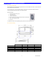
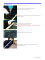
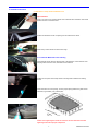
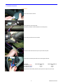
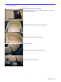
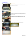
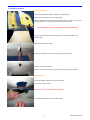
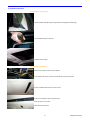
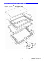
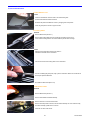
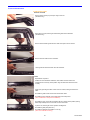
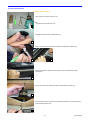
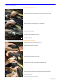
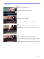
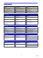
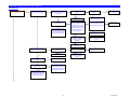
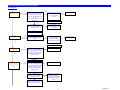
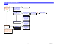
Inalfa Event Spoiler Series Installation and Service Manual Table of Contents Page(s) A. Product Overview 3 B. Preface 4 C. Installation Instruction D. Notes 5-12 13 E. Service Parts / Exploded Views 14-21 F. Service Guide 22-27 G. Trouble Guide 28-29 H. Trouble Chart 30-32 I. Inspection Sheet 33-34 Re-initialization of the SCU - see page 29 Inalfa Event Spoiler Series Installation and Service Manual A. Product Overview A.1.1 Features and Benefits The Event Spoiler is the most advanced technological spoiler sunroof and is available in four models: Event 450 HS, Event 450 OE, Event 450 QF, and Event 300 QF. The Event Spoiler gives you a safe and reliable installation, it passed all TUV Tests related to FMVSS and meets or exceeds all applicable FMVSS-Federal Motor Vehicle Safety Standards. Event Series Spoilers 1. Illuminated Switch with One Touch™ 2. Venus® Glass Panel 3. Integrated Wind Deflector 4. 450 HS is equipped with a Sliding Sunshade and built in louvered handle 5. Built in water management system 6. Auto Close For additional information, such as application guides, please visit us at www.inalfasunroofs.com A.1.2 Technical Drawing 300 QF 450 QF 450 OE 450 SS 15.75 x 29.5 19 x 32.25 19 x 32.25 19 x 32.25 Overall Frame 17 x 30.5 20 x 33.5 20 x 33.5 20 x 33.5 Overall Glass 15.125 x 28.75 18.25 x 31.75 18.25 x 31.75 18.25 x 31.75 Trim Panel 20.125 x 31.5 25 x 34.75 n/a 32.75 x 34 12.625 x 23 12.5 x 23 12.5 x 23 14.5 x 24.75 Template Trim Panel DLO 2 Product Overview Inalfa Event Spoiler Series Installation and Service Manual B. Preface B.1 Event Spoiler Operating Instructions The Event Spoiler can be operated in two modes Continuous and One Touch™ . Continuous mode allows the Event Spoiler to be operated by holding down the operating switch in either direction. Releasing the switch will stop the glass panel immediately. One Touch™ mode allows the Event Spoiler to be operated without holding the operating switch down and can be canceled by any switch activation. To Open, tap the operating switch on the backside of the switch marked with a white spot. The glass panel will go to a fully opened vent position. A second tap will fully open the roof. If desired, the sunshade can be closed in this position To Close, tap the operating switch on the front side of the switch. The glass panel will move to the fully opened vent position. A second tap will fully close the roof. Additional Features Auto Close function allows the sunroof to close automatically when switching off the vehicles ignition. During the Auto Close function, simply depress the switch to cancel, this will return the glass panel to the position it was in prior to the start of the Auto Close function, depressing the switch again will reactivate the Auto Close. Protective Stop Position: The Event Spoiler Sunroof is also protected against obstructions fixated on top of the car. If the glass panel hits a hard object it will stop moving immediately, this is a new stop position. After taking the object from the roof of the car bring the roof to the full open position and hold the switch for five (5) seconds, the glass panel will move to the original fully open position. B.2 Initialization Procedure To initialize, the following closed position must be defined. Turn on ignition In the closed position operate the front button of the switch until the relay clicking noise is noticed (Max 5 seconds). To complete the initalization process, the glass panel must be moved to the fully opened position using One Touch™ mode. 3 Preface Inalfa Event Spoiler Series Installation and Service Manual C. Installation Instructions C.1 Determine Application www.inalfasunroofs.com Determine the application by referring to the Assist Program or the Application Chart for that particular vehicle. Consideration should be given to dome lights and ribbed formed roof skins. If you are unsure of an application and you have access to the vehicle; the headliner may need to be removed if the vehicle is unfamiliar. C.2 Pre Installation Inspection Before you proceed, check to insure that you have all the components for a complete installation. Also, insure that none of the components have been damaged in shipping. Check for the following: Spoiler, Sunshade, Louver, Substrate, Hardware Bag At this time, using a 12v power source, test the functionality of the sunroof unit. Note: Leave the glass panel in the closed position during installation. Do not remove the motor. To initialization the SCU see 'Initialization Procedure ' in the Preface Section. C.3 Vehicle Prep for Installation Disconnect the negative side of the battery Protective Covers (Interior) Place protective covers on the following: Carpeting Steering Wheel Instrument Panel Seats Removal of Interior Trim Remove the following items: Sun visors / Retaining Clips Dome Lamps Coat Hooks 4 Protective Covers (Exterior) Place protective covers on the following: Hood Doors Deck Lid Exterior Glass Rear of Roof Clean Exterior Installation Instructions Inalfa Event Spoiler Series Installation and Service Manual C. Installation Instructions C.4 Sunroof Location Prior to aligning the substrate, check the roof bow location and the interior wires. Position the substrate against the factory headliner. Allow for consoles and sun visors when determining the position. From the front center of the substrate opening, mark and make an up ding. From outside the vehicle locate the up ding and measure 2 front edge of the cutting template with the mark. 1/4" forward and mark. Align the Using a grease pencil mark a line on the roof skin, follow the outside edge of the template. Remove the template. Using 2" wide tape, apply the tape to the roof skin approximately an 1/8" outside of the marked line of the cutting template. Caution: Pay close attention to Side Curtain Airbags and Roof Bows. C.5 Removal of Roof Bows and Roof Insulation Using a wide putty knife with the corners ground off, remove any roof insulation or silencer material. Break the bond between the roof bows and the roof skin using an automotive windshield removal kit. These kits may be purchased through your local glass company or use .035 piano wire. Insert a protective plate between the roof skin and the roof bow at the side rail, to prevent damage to the roof skin. Cut the roof bows flush with the factory side rails using aviation snips or other cutting tools. NOTE: Retain roof bow for later use if dome lamp is mounted on roof bow. C.6 Cutting Roof skin Using an air chisel, cut a starter hole approximately 3" in diameter in the center of roof opening. Using Bosch Shears, cut your opening approximately 1" inside of the marked line. Using Bosch Shears, make your final cut by cutting on the marked line. Note: When cutting with Bosch shears, always cut in counter clockwise direction. 5 Installation Instructions Inalfa Event Spoiler Series Installation and Service Manual C. Installation Instructions C.7 Mainframe / Clamp Frame Installation Remove 4 screws retaining the lower clamp frame to the mainframe. Remove 1 motor screw, the Motor remains in place. Pre-fit the Spoiler unit into the roof opening to insure that the opening is a minimum of 1/16" larger than the mainframe. Prime the cut edge using an anti-corrosive metal primer. Remove the masking material from the roof surface. Reminder: Always peel the masking tape towards the opening to prevent the paint from flaking. Insert the eight (8) speed clips to the mainframe as shown. Apply the supplied butyl to the leading inner edge of the flange on the mainframe. Remove tape showing the butyl. 6 Installation Instructions Inalfa Event Spoiler Series Installation and Service Manual C. Installation Instructions C.7 Mainframe / Clamp Frame Installation cont. Optional Method: Apply a 1/4" bead of non-corrosive silicone to the underside of the mainframe. Care should be taken to insure a continuous bead. Position the mainframe into the roof opening from the outside of the vehicle. Clean off any excess silicone around the frame edge. C.7.2 Install the Mainframe to the Trim Ring From inside the vehicle raise the clamping frame to the Mainframe. Attach the front of the clamping frame around the motor, then attach to the mainframe. Position the rear portion of the clamp frame to mounting frame and attach the retaining screws. Insert shim at the rear of the opening, to insure proper spacing between the glass and the mainframe, approximately 1/8" (3.30mm) thick. Caution: Over tightening the screws will cause the roof skin distortion and under tightening could cause improper compression. 7 Installation Instructions Inalfa Event Spoiler Series Installation and Service Manual C. Installation Instructions C.8 Electrical Connect the harness to the SCU. Connect the SCU to the clamp frame. Dual lock is provided for the SCU attachment to the clamp frame. Connect the ground wire to the front header. Route the harness wires down the A-post. Tape the wires into place. Connect the red and blue power wires to the vehicles ignition harness. Connector Wire Number 1 (Red ) Wire Number 2 (Black) Wire Number 3 (Blue) Power with ignition off 12V Ground 0V Power with ignition on 12V Ground 12V Reconnect the vehicle battery and test cycle the spoiler to verify it is fully functional. 8 Installation Instructions Inalfa Event Spoiler Series Installation and Service Manual C. Installation Instructions C.9 Substrate Prep. C.9.1 Removing the Sunshade from the substrate Pull the sunshade forward. Using a hook tool release the side blocks on one side, lift and pull the sunshade from the guides. Tape the track guides with masking tape to avoid prolonged clean up. Pre spray glue to the leading edge for headliner retention. C.9.2 Substrate mounting Install substrate to the mainframe using a T-20 torque bit driver. Install all 10 T-20 substrate retaining screws. 9 Installation Instructions Inalfa Event Spoiler Series Installation and Service Manual C. Installation Instructions C.10 Wrapping the Sunshade Cut a 24 x 30 inch piece of headliner material and spray, with trim adhesive, the backside and edges of the sunshade panel. Place the shade panel off to the side and spray the rest of the headliner material with trim adhesive. Spray glue to the face side of the sunshade and headliner material. Return the shade panel to the glued side of the headliner material then turn the shade panel with the headliner material over. Starting in the center smooth and pull the fabric from the center to the outer edges. Turn the shade panel over and adhere the material to the side edges as shown. Trim away any extra material. Wrap the material over the rear and front edge of the sunshade. Trim material from the shade slide block holes and louvers for the shade handle. Install the handle with provided press nuts (4). Finished product 10 Installation Instructions Inalfa Event Spoiler Series Installation and Service Manual C. Installation Instructions C.11 Wrapping the Headliner Trim the factory hardboard headliner; allowing for substrate clearance. Measure enough material to cover the headliner board. Apply trim adhesive to the back side of the new headliner material Allow 5 - 10 minutes for both glues surfaces to set-up. (Glued surfaces will feel tacky to the touch) Use Headliner Material that meets FMVSS 302 Specification (Flammability) Trim the excess material around the outer edge, visors, consoles and handles of the headliner board. Install the headliner into the vehicle. Pull the switch harness through he switch opening and connect the switch. Insert the switch into the substrate. Install the visors and retaining clips; insuring that the headliner is properly positioned. C.12 Wrapping Opening. Pre glue the headliner material in the area to be wrapped. Cut relief cuts in all four corners. Caution: Do not over cut the material for it may show. Pull and tack the headliner material to the leading edge. 11 Installation Instructions Inalfa Event Spoiler Series Installation and Service Manual C. Installation Instructions C.12 Wrapping Opening Cont. Trim the headliner material leaving enough material for wrapping the leading edge. Tuck the material using a tucking tool. Complete interior build up. C.13 Sunshade Installation Place the Event Spoiler unit into the open position. From outside of the vehicle, position the sunshade clips into the track guides. Pull the sunshade forward to insure proper function. Cycle the Event Spoiler to test for proper function. Clean the interior of the vehicle. Water test the Event Spoiler. 12 Installation Instructions Inalfa Event Spoiler Series Installation and Service Manual Notes: 13 Notes Inalfa Event Spoiler Series Installation and Service Manual 14 inalfa EVENT 300 Compact QF Inalfa Event Spoiler Series Installation and Service Manual Index No Description Repair Code Part Number TR300 2400444A70 1 Trim Ring Assy w/ Fastening Clips 2 Main Frame w/ Mechanism MF300QF 3800202A70 3 Clamp Frame w/ Trim Ring Brackets CF300QF 3800203A70 4 Locking Slider LH LSL 4110115A70 5 Locking Slider RH LSR 4110116A70 6 Set of Fastening Clips FC300 4180165C00 7 Screw Kit SK300 4180170A11 8 Wiring Harness Electronic WHE300 4200089A11 9 Motor Assy Electronic MTR300QF 5380040A70 10 SCU SCU300QF 6070016A70 11 Main Seal MS300QF 7400673A70 12 Operating Switch OS300QF 8050050A70 13 Glass Assy GA300QF 8840191A70 BUTY 10800040A70 HKE300 4180172A11 Not shown on diagram: Butyl Seal Fitting Hardware Kit Electronic Set of Trim Ring Brackets 4180171A11 15 inalfa EVENT 300 Compact QF Inalfa Event Spoiler Series Installation and Service Manual 16 inalfa EVENT 450 QF Inalfa Event Spoiler Series Installation and Service Manual Index No Description Repair Code Part Number TR450QF 2400443C00 1 Trim Ring Assy w/ Fastening Clips 2 Wind Deflector Assy 3 Main Frame w/ Mechanism MF450QF 3800197C00 4 Clamp Frame w/ Trim Ring Bkts CF450QF 3800198C00 5 Locking Slider LH LSL 4110115A70 6 Locking Slider RH LSR 4110116A70 7 Screw Kit SK450QF 4180163A11 8 Set of Fastening Clips FC450QF 4180165C00 9 Wiring Harness Electronic WHE450QF 4200089A11 10 Motor Assy Electronic MTR450QF 5380040A70 11 SCU SCU450QF 6070016A70 12 Main Seal MS450QF 7400672A70 13 Rollo Assy RA450QF 7500012A70 14 Operating Switch OS450QF 8050050A70 15 Glass Assy GA450QF 8840190A70 BUTY 10800040A70 HKE450QF 4180168A11 N/A Not shown on diagram: Butyl Seal Fitting Hardware Kit Electronic 17 inalfa EVENT 450 QF Inalfa Event Spoiler Series Installation and Service Manual OE/FF 18 inalfa EVENT 450 OE Inalfa Event Spoiler Series Installation and Service Manual OE/FF Index No Description Repair Code Part Number WFA450OE 3800199A70 1 Wrap Frame Assy 2 Wind Deflector Assy 3 Main Frame w/ Mechanism MF450OE 3800201A70 4 Clamp Frame Assy CF450OE 3800200C00 5 Locking Slider LH LSL 4110115A70 6 Locking Slider RH LSR 4110116A70 7 Screw Kit SK450OE 4180166A11 8 Wrap Frame Screws WFS450 4180167A11 9 Wiring Harness Electronic WHE450OE 4200089A11 10 Motor Assy Electronic MTR450OE 5380040A70 11 SCU SCU450OE 6070016A70 12 Main Seal MS450OE 7400672A70 13 Rollo Assy RA450OE 7500012A70 14 Locking Strip LS450OE 7980003A70 15 Operating Switch OS450OE 8050050A70 16 Glass Assy GA450OE 8840190A70 17 Protection Pads PP450OE 6100003A70 18 Switch Plate Assy SPA450OE 6400308A70 BUTY 10800040A70 HKE450OE 4180169A11 N/A Not shown on diagram: Butyl Seal Fitting Hardware Kit Wrap Electronic 19 inalfa EVENT 450 OE Inalfa Event Spoiler Series Installation and Service Manual 20 inalfa EVENT 450 HS Inalfa Event Spoiler Series Installation and Service Manual Index No Description Repair Code Part Number CA450HS 2400479E41 1 Cover-Assy P177 H/S 2 Wind Deflector Assy 3 Main Frame w/ Mechanism HS MF450SS 3800206A70 4 Clamp Frame Assy CF450OE 3800200C00 5 Locking Slider LH LSL 4110115A70 6 Locking Slider RH LSR 4110116A70 7 Screw Kit SK450HS 4180166A11 8 Fastener Bag FB450HS 4180191C00 9 Wiring Harness Electronic WHE450HS 4200089A11 10 Motor Assy Electronic MTR450SS 5380040A70 11 SCU SCU450SS 6070016A70 12 Main Seal MS450SS 7400672A70 13 Operating Switch OS450SS 8050050A70 14 Glass Assy GA450SS 8840190A70 15 Panel-P177 Hardshade PHS450SS 6200970C41 16 H/ware Bag Sunshade Spring HBSSP450HS 4180173A11 17 Louver-Assy P177 H/S LA450HS 4980004A70 BUTY 10800040A70 Fitting Hardware Kit Wrap Electronic HKE450OE 4180169A11 Kit-Base P177 H/S KHS450SS 4730156A00 Kit-Base P177 Trim KT450SS 4730215A00 SCR450HS 7310118A70 N/A Not shown on diagram: Butyl Seal Screw-P177 Hardshade 21 inalfa EVENT 450 HS Inalfa Event Spoiler Series Installation and Service Manual F. Service Set Instructions F.1 Glass Panel Removal: Cycle the glass panel into the open position. Allowing access to the four (4) T-25 torx screws. Remove four (4) T-25 torx screws, save for new glass installation. Remove the Glass Panel. Install: Install the new glass panel using the existing four (4) T-25 glass screws. Apply a thread lock material before reattaching the screws. F.2 Sunshade Panel (450 HS only) Removal: Cycle the glass panel to full slide open position. Pull the sunshade forward. With a hook tool release the side blocks from one side, lift and pull the sunshade from the sunroof housing. Wrap the new sunshade with matching headliner material (see C10. Wrapping the Sunshade) Install: With the sunshade in position, insert the sliding blocks on one side, pull opposite the sliding blocks inward and engage into the mechanism guides. Re-install the Glass Panel (see D.2.1). F.3 Wind Deflector (450 series only) Removal Open the Glass Panel. Remove the plastic WD cover at the rear end of each WD spring. Deflect the wind deflector rearward and up to release from the mechanism guide. 22 Service Guide Inalfa Event Spoiler Series Installation and Service Manual F. Service Set Instructions F.3 Wind Deflector cont. Install Insert the wind deflector arms into slots in the mechanism guide. Pivot the wind deflector forward and down Re-attach the plastic wind deflector covers by snapping them into position. Close the glass panel to check for proper function. F.4 Locking Sliders Removal Remove Glass Panel (see D.2.1) Remove both locking sliders from the mechanism by sliding it to the front. If at one side the locking slider is not broken break the part as shown in image. Install Slide the new locking slider from the front side in a backwards movement on the mechanism. Click the front hook of the locking slider on the mechanism. Prior to re-installing the glass panel, fully cycle the mechanism. Return the mechanism to the full open position afterwards. Re-install the Glass Panel (See D.2.1) F.5 Mechanism LH/RH Removal Remove Glass Panel (see D.2.1). Remove the Headliner substrate assembly. Remove the motor connector from the SCU. Remove the clamp frame and motor; take the frame assembly out of the vehicle and lay the frame assembly upside down on a bench. Clean the roof skin of the vehicle 23 Service Guide Inalfa Event Spoiler Series Installation and Service Manual F. Service Set Instructions F.5 Mechanism LH/RH Removal continued Remove the four plastic pop rivet caps using a hook tool. (450 Series only) Drill out the four rivets, retaining the mechanism guides to the mainframe. (450 Series only) Remove the mechanism guide and drive cable center plate T-25 torx screws. Remove the drive cable from the mainframe. Lift the guide and cable mechanism from the mainframe. Install Replacement component. Position the new mechanism assemblies, drive cables and tubes. Ensure the mechanisms are in the fully closed position. Align the drive tubes and return tubes correctly. Apply super glue along the sides of each of the four tubes; bonding the tubes to the frame. Re-install the guide screws and the Drive Cable Center Plate. Re-install the frame assembly in the vehicle and mount clamp frame (See- C7 Mainframe / Clamp Frame Installation) Re-install the motor, ensure the mechanisms still are in the full closed position (locking sliders fully forwards) and re-connect the connector to the SCU. Cycle the unit, checking for correct operation and alignment. Re-install the glass panel (See D.2.1) Re-install the substrate and headliner or trim ring (See- C.9.2 Substrate mounting.) 24 Service Guide Inalfa Event Spoiler Series Installation and Service Manual F. Service Set Instructions F.6 Motor Removal / Install Tools required to remove the SCU & motor. For 450 HS use the Scuw Driver tool. 1 Disengage the switch from the headliner/trim ring. 2 Using a hook tool pull the material from backside of the hardboard. (450HS only) 3 4 Carefully peel back the headliner material to gain access to the attachment screws. (450 HS only) 5 Remove the T-25 screws retaining the bezel to the mainframe. (450 HS only) 6 Remove enough screws so the bezel can be deflected downwards, to gain access to the motor assembly. (450 HS only) 7 25 Service Guide Inalfa Event Spoiler Series Installation and Service Manual F. Service Set Instructions F.6 Motor Removal / Install cont. Remove the motor from the mainframe by removing the three(3) T-25 screws. 8 Retain the three(3) T-25 screws for the motor replacement. 9 Remove the motor assembly. Re-install the motor following steps 10 thru 1. 10 Re-install the headliner. F.7 SCU Removal and Replace Follow the motor removal procedure steps 1 thru 7. Disengage the SCU from the mainframe. Unplug the harness connector from the SCU. Unplug the motor connector from the SCU and replace the SCU. Follow the removal procedures for reattaching the SCU and motor assembly. Re-install the headliner. Tuck the headliner material into position. 26 Service Guide Inalfa Event Spoiler Series Installation and Service Manual F. Service Set Instructions F.8 Seal Removal Removal Cycle the Glass Panel to full slide open position. Using a screwdriver, lift the seal section from the mainframe. Remove the seal section from the mainframe. Clean and remove any excess silicone from the seal retaining channel. Install Apply a 3mm bead of silicon adhesive in the outer corner of the frame groove. Apply an additional bead of silicon adhesive in the inner corner of the groove along the front of the frame. Insert the new seal, starting in the four corners. equally dividing the seal. Insert the Seal in between the corners. Ensure that the seal is not pulled out or pressed down in the corners. Cycle the glass panel during the mounting of the seal; to achieve easy access. Cycle the glass panel to closed position and allow for a minimal of 4 hours currying time. 27 Service Guide Inalfa EVENT Installation Manual and Service Manual G. Trouble Shooting Guide Mechanical Failures Problem Possible Cause Solution Panel misaligned LH/RH Timing of drive cables incorrect Re-time drive cables Glass panel stopping prematurely. Obstacle in mechanism or guide rail Remove obstacle Cable ratcheting Check the motor and cable tube at motor bracket and motor insert Align cable tube to motor bracket and reinstall motor properly. Electrical Failures Problem Possible Cause Solution Operating of the sunroof is possible, no auto close, no one touch SCU in degraded mode due to malfunction Refer to B.2. Re-initilization Procedure SCU makes clicking noise but panel will not move Low voltage Check power supply Panel is sliding too slowly. With a 13.5v power supply, the panel should not take more than 7sec. To close from fully opened position. Weak battery Misaligned panel creating drag Weak motor Dirty mechanism Change or replace motor Clean and grease mechanism or replace. Rattling Noise Problem Possible Cause Solution Hardshade Loose attachment screws Tighten all T-25 attachment screws Sunshade rattling Check for felt pads on sunshade Add felt pads to sunshade Rattle in motor area Loose screws on motor Tighten screws or replace Wind Noise Problem Excessive wind noise when the panel is in the closed position Possible Cause Solution Locking slider broken, replace Locking Slider Panel seal not tight to glass panel Seal deformed, replace seal Water Leaks Problem Water coming through panel opening area or headliner wet Possible Cause Solution Locking slider broken, replace Locking Slider Panel seal not tight to glass panel Seal deformed or damaged, replace seal 28 Trouble Guide Inalfa EVENT Installation Manual and Service Manual G. Trouble Shooting Guide Testing Electrical Components Make sure that during the test of electrical components the Inalfa EVENT Spoiler is connected to a 12V source. If the roof is installed in a car, the battery needs to be connected and operable. During test period, the ignition/accessory switch must be on. This test can be accomplished with a voltage meter or test light. Inspect and make sure that the fuses are not blown. Cable harness and motor inspection requires the removal of the headliner. Wire Harness SCU to Battery Connector Wire number 1 (red) Wire number 2 (black) Wire number 3 (blue) Power on wire if ignition is off 12V Ground 0V Power on wire if ignition is on 12V Ground 12V Motor Disconnect the motor wire from the SCU. If the mechanism is jammed remove the motor from the frame. Use a double wire of sufficient length, connect directly to battery and inspect the motor for proper operation in both directions. This is done by reversing the connection of the double wire. The motor has an inbuilt thermal cut-out device that automatically switches the motor off during periods of overload. After a cooling down period the motor will function properly. Brown + Blue lead on motor to test power SCU Testing is covered in the electronic trouble chart. The following failures could be a result of a defective SCU No action on continues operation One Touch operation inoperative Auto Close function inoperative No action on continues operation One Touch operation inoperative After replacing the SCU, the SCU must then be re-initialized. Proceed with the electronic trouble chart if the problem is not solved by initialization. Re-initialization of the SCU To re-initialize, the following closed position must be defined. Turn on ignition. In the closed position operate the front button of the switch until the relay clicking noise is noticed (Max 5 seconds). To complete the reinitalization process, the glass panel must be moved to the fully opened position using One Touch™ mode. 29 Trouble Guide Inalfa EVENT Installation Manual and Service Manual H. Trouble Chart Is the motor running with ignition switched on? no Is the switch illuminated? (ignition contact switched on). yes no yes Is the fuse of the red contact wire blown? ignition contact switched on yes Has the fuse been replaced before? no yes no Replace Fuse Power (12v) on red contact wire of SCU? no Break or bad contact in wire harness between fuse and SCU, replace wire harness or solve bad connection. yes Fuse smaller than 20 amps? yes Mount a fuse of 20 amps (red) yes Switch failure no Short circuit in wire harness, replace wire harness yes Disconnect motor from SCU. Check the correct functioning of the motor by connecting the motor wires to a separate power source. Is the motor functioning in both directions? Re-connect motor connector to SCU and replace switch. Is the roof functioning normal? no no SCU failure, replace SCU no Remove motor from sunroof frame. Is the motor functioning in both directions? yes Mechanical problem. Check mechanism for obstruction or failure no Motor broken, replace motor. Is the fuse of the blue ignition contact switched on yes Has the fuse been replaced before? yes Fuse smaller than 5 amps? yes no Replace Fuse no Short circuit in wire harness, replace wire harness no Replace switch, problem solved? yes Mount a fuse of 5 amps (blue) Switch failure no Power (12v) on blue contact wire of SCU? no yes Break or bad contact in flat cable between fuse and SCU, replace wire harness or solve bad connection. Break or bad contact in wire harness between fuse and SCU, replace wire harness or solve bad connection. 30 Trouble Chart Inalfa EVENT Installation Manual and Service Manual H. Trouble Chart Is the motor running in both directions? no yes yes Disconnect motor from SCU. Check the correct functioning of the motor by connecting the motor wires to a separate power source. Is the motor functioning in both directions? Re-connect motor connector to SCU and replace switch. Is the roof functioning normal? yes Switch failure no no SCU failure, replace SCU no yes Remove motor from sunroof frame. Is the motor functioning in both directions? Mechanical problem. Check mechanism for obstruction or failure no Motor broken, replace motor. yes Is the motor running normal? no Is the motor running for only a short time after operating the switch? yes Motor connector not properly yes mounted. Remove connector and mount properly. Problem solved? Problem solved yes no Replace motor Is the one touch functioning? no yes Re-initialize SCU by running the yes sunroof to closed position and keep-on pushing the switch. After 3 seconds the SCU confirms reinitialization by kicking back. Problem solved? Problem solved no Replace SCU Is it possible to open the roof in its maximum opened position? yes no Re-initialize SCU by running the yes sunroof to closed position and keep-on pushing the switch. After 3 seconds the SCU confirms reinitialization by kicking back. Problem solved? no Can the sunroof be placed in all positions using the manual override on the motor? no Mechanical problem. Obstruction or failure of mechanism. Remove obstruction or solve failure. yes Problem solved Blue wire is not connected via ignition. Search for another contact wire which is switched by the ignition contact. 31 Trouble Chart Inalfa EVENT Installation Manual and Service Manual H. Trouble Chart Re-initialize SCU by running the yes sunroof to closed position and keep-on pushing the switch. After 3 seconds the SCU confirms reinitialization by kicking back. Problem solved? no The roof is experiencing false reversal during one touch or auto close operation Problem solved yes no False reversal also occurs during yes one touch closing motion? no Sunroof does not close also yes not after completing the 5 retry closing motions Remove glass panel and test the sunroof. Problem solved? no Obstacle in mechanism. no High resistance of mechanism whereby the anti trap protection is activated. Clean and lubricate mechanism with Molycoat based grease. Is the auto close functioning? no yes Electronics Fully Tested and Okay. Remaining problems are not caused by the SCU, Motor, Wire harness or Switch. Please continue with the mechanical trouble shooting guide. False reversal only occurs during yes auto-close High resistance of mechanism whereby the anti trap protection is activated. Clean and lubricate mechanism with Polycoat based grease. yes Blue wire is not connected via ignition. Search for another contact wire which is switched by the ignition contact. Power (12v) on blue wire SCU with ignition off? no Replace SCU 32 Trouble Chart Inalfa Event Spoiler Series Installation and Service Manual I. Inspection Sheet An inspection report will help reduce the number of complaints from your customer. Be sure the vehicle is clean and the Owners Manual is placed in the glove box prior to delivery. Inspection Sheet Serial #: VH#: Date: Dealer: Yr/Make/Model: Mileage: Inspection by: Installation by: Stock #: VIN #: Type of Roof: Wind Deflector: Power Wires: Hot Switched Cut line: Yes No Switch Location: Headliner Used: Inspection before Install OK REJECT REJECTION OK'd 1. Examine entire vehicle for dents, dings and scratches 2. Check all electrical functions of vehicle 3. Sign off on inspection form Initial: 4. If defects are found contact sunroof manager or sales manager and have them sign off on our inspection report. Dealer initial: In-process inspection (Before Headliner) OK REJECT REJECTION OK'd 1. Wiring glued and taped correctly 2. Check for correct wiring procedure and functionality 3. Check dome light for proper functions 4. Note defect and report to installer and supervisor 5. After correction, re-inspect and sign form Initial: Inalfa Event Spoiler Series Installation and Service Manual 33 Inspection Sheet Inalfa Event Spoiler Series Installation and Service Manual I. Inspection Sheet Inspection Sheet Final Inspection OK REJECT REJ OKED 1. Water test Event Spoiler 2. All plastic trim and components are properly installed? 3. Top of roof is cleaned and waxed? 4. Interior is cleaned of debris and glue (metal shavings in seat crevice)? 5. Check for any tools left in car 6. Roof operates properly: Roof closes from open with one touch Roof closes from vent with one touch Roof closes from open with auto close Roof closes from vent with auto close Roof auto-reverses from vent to close Roof auto-reverses from open to close 7. Interior lights work: 8. Glass panel is clean: Inside Outside 9. Test drive: No wind noise No rattles with roof shut No rattles with roof open 10. Make sure switch is secure. 34 Inspection Sheet