1
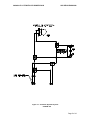
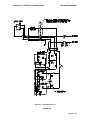
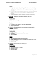
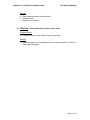
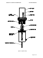
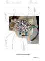
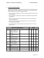
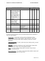
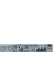
Wipaire, Inc.
1700 Henry Avenue
South St. Paul, MN 55075
Phone: 651-451-1205
Fax:
651-451-1786
CESSNA MODEL 206
ON FLI-LITE 4000 WITH HYDRAULIC POWER PACK
SERVICE MANUAL
AND
INSTRUCTIONS FOR CONTINUED
AIRWORTHINESS
ISSUED OCTOBER 20, 2004
CONTACT WIPAIRE SERVICE DEPARTMENT
OR CHECK OUR WEBSITE AT WWW.WIPAIRE.COM
FOR LATEST REVISIONS
206/4000 FLI-LITE WITH HYD POWER PACK
SKI SERVICE MANUAL
LOG OF REVISION
REV.
NO.
ORIG
PAGES
ALL
DESCRIPTION
DATE
OCT. 20 2004
Page 2 of 16
206/4000 FLI-LITE WITH HYD POWER PACK
SKI SERVICE MANUAL
INTRODUCTION
This manual describes the general servicing and maintenance for the Model 4000 FLILITE ski hydraulic power pack installation. For services and repairs not covered by this
manual contact the factory.
The service products referred to throughout this manual are described by their trade
name and may be purchased from the factory Parts Department.
To contact Wipaire for service assistance or parts sales, call or write:
Wipaire, Inc.
Telephone: (651) 451-1205
Fax: (651) 451-1786
Page 3 of 16
206/4000 FLI-LITE WITH HYD POWER PACK
5.
SKI SERVICE MANUAL
RETRACT SYSTEM OPERATION AND MAINTENANCE
5.1 Description and Operation
Retraction and extension of the main and nose skis is affected by a hydraulic
actuation system shown schematically in Figure 5-1. Figure 5-2 shows the
electrical schematic.
The gear system is hydraulically actuated and driven by one reversible electric
pump.
A pressure of between 500 psi and 700 psi in the down and 500 psi and 700 psi in
the up position is maintained in the supply line. When the pressure falls below 500
psi in the down position and 500 psi in the up position, the pressure switch activates
the pump solenoid, providing power to the pump. When the pressure reaches 700
psi in the down position and 700 psi in the up position, the pressure switch
deactivates the solenoid and the pump motor stops. A check valve on the output
side of the pump retains
pressure in the system while the pump is off. The pump has an interval relief valve
that directs oil back to the pump reservoir when the line pressure exceeds 800
+100/-0 psi. The system also has an internal relief valve to protect against thermal
expansion when line pressure exceeds 1100 +100/-0 psi.
See Section 8 for disassembly, service and troubleshooting.
The system requires hydraulic oil (Mil-H-5606 Red). To check the fluid level, fill the
reservoir with hydraulic oil and cycle the gear. If the reservoir empties (i.e., fluid
disappears in sight glass), stop the cycle by pulling the circuit breaker on the control
panel. Fill the reservoir again and complete the cycle. Continue this procedure
until the fluid level in the reservoir stabilizes (it will vary in level between up and
down positions). If the fluid level continues to decline during gear cycles, check for
external leaks. If pump cycles on and off during gear cycle, it may be necessary to
select hand pump to UP. Cycle gear UP with electric pump, then select gear
DOWN on hand pump and cycle gear DOWN with electric pump. Repeat if
necessary. This manually bleeds system.
NOTE
Fluid level in reservoir in UP position is full; DOWN position
reservoir is half full. Don t over fill in DOWN position.
A cockpit-mounted switch accomplishes the selection of gear up or gear down
Page 4 of 16
206/4000 FLI-LITE WITH HYD POWER PACK
SKI SERVICE MANUAL
Figure 5-1. Schematic Hydraulic System
CESSNA 206
Page 5 of 16
206/4000 FLI-LITE WITH HYD POWER PACK
SKI SERVICE MANUAL
Figure 5-2. Schematic Electrical
CESSNA 206
Page 6 of 16
206/4000 FLI-LITE WITH HYD POWER PACK
SKI SERVICE MANUAL
6.3 Gear Selector Switch
The gear selector switch is located on the instrument panel in front of the pilot.
The gear selector is an electrical switch that changes pump direction of the electropower pack for gear up or down. The red light on panel indicates the pump has
power supplied to it
8.
HYDRAULIC PUMP DISASSEMBLY AND SERVICE
Pump may be returned to factory for service. Electric pump motor may be returned
to factory for service.
The pump is located on the fuselage side just aft of access panel in the baggage
compartment. The entire pump assembly maybe removed from the aircraft by
removing the (2) top and (2) lower bolts securing the pump bracket to the fuselage
bracket. Remove hydraulic lines and unplug wiring harness. Remove assembly
from aircraft.
The screens maybe cleaned by the following, without removing pumps from the
aircraft.
1) Remove return line on lower reservoir and drain oil.
2) Remove screw on bottom of reservoir for tank removal.
3) After tank removal, pick up filters to be pulled off (friction fit) and cleaned.
(Refer to Figures 8-1 & 8-2.)
4) Replace tank, reinstall lower hose and fill with clean hydraulic oil (Mil-H-5606).
5) Fill by removing breather and filler stand pipe.
NOTE: ANY PARTS THAT MAYBE REQUIRED TO REPLACE REFER TO
WIPAIRE 206 WIPLINE 3450 PARTS CATOLOG ON WEB SITE
WWW.WIPAIRE.COM
8.1 Setting Thermal and Pressure Relief Valves
1)
2)
3)
4)
These are preset at the factory. Thermal relief is set at 1100° +100/-0 PSI and
pressure relief at 800° +100/-0 PSI.
If adjusting, refer to Figure 8-2 for location of relief valves.
Loosen jam nut on relief valve to be changed. Turn clockwise to increase and
clockwise to lessen.
Do not exceed factory settings noted above.
8.2 Troubleshooting Hydraulic System
1)
PROBLEM
Power pack does not run after gear selection.
RED pump light OFF
Probable cause:
a. Circuit breaker has tripped.
b. Pressure switch not pulling in at low cut in.
c. Solenoid switch not pulling in.
Page 7 of 16
206/4000 FLI-LITE WITH HYD POWER PACK
SKI SERVICE MANUAL
d. Motor not properly grounded.
e. Pressure buildup on both sides of up and down lines.
PROBLEM
Power pack does not run after gear selection.
RED pump light ON
Probable cause:
a. Faulty pump motor.
Verification and Remedy:
a. Reset circuit breaker.
b. Short across pressure switch leads and see if motor runs. If motor
operates, replace pressure switch.
c. Short across solenoid pressure switch leads and see if motor runs. If motor
operates, replace solenoid pressure switch.
d. If c. above does not produce results and it is verified that voltage was
actually applied to motor, it can be assumed motor is bad or not properly
grounded.
e. Check motor ground.
f. Select hand pump to up and down position to relieve pressure. Return to
center and select gear.
2)
PROBLEM
Power pack does not shut off after gear reaches position.
a. Faulty pressure switch.
b. Faulty or dirty pressure relief valve allowing insufficient pressure buildup.
Remedy:
a. Replace pressure switch.
b. Clean and check relief valve.
3)
PROBLEM
Power pack shuts off before gear reaches position.
Probable Cause:
a. Binding, jammed or frozen gear retractor, which causes pressure to build
up (and stay up), and pressure switch shuts off power pack.
Remedy:
a. Repair retractor.
4)
PROBLEM
Power pack cycles on and off after gear is in position.
Probable Cause:
Page 8 of 16
206/4000 FLI-LITE WITH HYD POWER PACK
SKI SERVICE MANUAL
a. Internal hydraulic leak.
b. External hydraulic leak.
Page 9 of 16
206/4000 FLI-LITE WITH HYD POWER PACK
SKI SERVICE MANUAL
Remedy:
a. Verify leak is not external by checking fluid level in reservoir and looking at
couplings for oil leaks. If no external leaks are found, disconnect and cap
off the hydraulic actuators one at a time and find the leaky one by process
of elimination.
b. If isolating entire system still indicates internal leak, power pack check valve
(located in pressure port of pump) is bad and needs replacement or
reseating.
c. Visually inspect lines, cylinders, and hoses and replace as necessary.
5) PROBLEM
Power pack cycles on and off during gear cycle.
Probable Cause:
a. Binding in retraction unit.
b. Pressure switch cut off limit too low.
Remedy:
a. Investigate for free operation. Check gear that retracts last.
b. Replace pressure switch.
6) PROBLEM
Slow gear operation cycle (considerably longer than 30
seconds).
Probable Cause:
a.
b.
c.
d.
Plugged oil screen.
Poor electrical connection to motor. Check ground.
Poor motor.
Worn pump gears.
Remedy:
a. Clean intake screen located inside reservoir tank.
b. Connect motor direct to 12/24-volt source and note operation poor, motor
needs overhaul.
c. Covered in (b) above.
d. Replace pump
7) PROBLEM
Circuit breaker pops during cycle.
Probable Cause:
a. Wire connections bad or corroded.
b. Bad motor brushes.
c. Bad circuit breaker.
Page 10 of 16
206/4000 FLI-LITE WITH HYD POWER PACK
SKI SERVICE MANUAL
Remedy:
a. Clean and protect terminal with grease.
b. Overhaul motor.
c. Replace circuit breaker.
8) PROBLEM
Power pack does not cycle up or down.
Probable Cause:
a. Pressure build-up in both sides of up and down lines.
Remedy:
a. Select hand pump to up and down position to relieve pressure. Return to
center and select gear.
Page 11 of 16
206/4000 FLI-LITE WITH HYD POWER PACK
SKI SERVICE MANUAL
Figure 8-1. Hydraulic Pump
Page 12 of 16
206/4000 FLI-LITE WITH HYD POWER PACK
SKI SERVICE MANUAL
Figure 8-2. Internal View Hydraulic Pump
Page 13 of 16
206/4000 FLI-LITE WITH HYD POWER PACK
9.
SKI SERVICE MANUAL
CONTINUED AIRWORTHINESS
As coded in the Inspection Time Intervals chart in this section, there are items to be
checked each 25, 50, 100, and 200 hours. Also there are notes on special items
which may require servicing at more frequent intervals.
· When conducting an inspection at 25 hours, all items marked for 25 hours would
be accomplished.
· When conducting an inspection at 50 hours, the 25 and 50-hour items would be
accomplished.
· When conducting an inspection at 100 hours, the 25, 50, and 100-hour items
would be accomplished.
· When conducting an inspection at 200 hours, the 25, 50, 100, and 200-hour
items would be accomplished.
· A complete inspection (Annual Inspection) would include all 25, 50, 100, and
200-hour items.
INSPECTION TIME INTERVALS
25
Electrical
System
Landing
Gear
Systems
Pump and Indicator Light
Wiring Inspect for
chafing, broken or loose
terminals and general
condition.
Solenoids Inspect wiring,
mounting and general
condition.
Pressure Switches
Inspect wiring, mounting
and general condition.
Pump Motors Inspect
wiring, mounting and
general condition.
Gear Pivot Inspect for
condition, lubrication,
corrosion and paint.
Nose and Main Wheel
Bearing Grease zerk
fittings.
Hydraulic Fluid Level
Wheels and Tires Inspect for
wear, pressure, condition.
Brake Assemblies Inspect
for wear, corrosion, leakage.
HOURS
50 100
200
X
X
X
X
X
X
X
X
X
X
Page 14 of 16
206/4000 FLI-LITE WITH HYD POWER PACK
SKI SERVICE MANUAL
INSPECTION TIME INTERVALS
25
Hydraulic Fluid Screen
Clean and inspect. Note: If
floats sit for extended periods
of time (i.e., if removed
during winter months),
screen should be cleaned
before putting floats back into
service. Hydraulic fluid in
reservoir should be checked
for moisture or other
contaminates and changed if
necessary.
Main and Nose Gear
Actuator, Assemblies
Inspect for condition,
lubrication, leakage,
corrosion and cleanliness.
Hydraulic lines Inspect for
leaks, condition and security.
Perform Retraction Test
HOURS
50 100
200
X
X
X
Main Gear Inspect up and
down for proper
engagement.
Perform emergency gear
Extension (hand pump).
X
X
Nose and Main Wheel
Bearings Disassemble and
inspect.
X
As general inspection guidelines, each of the following areas should be inspected for
their own unique attributes:
Movable Parts For lubrication, servicing, security of attachment, binding,
excessive wear, safetying, proper operation, proper adjustment, correct travel,
cracked fittings, security of hinges, defective bearings, cleanliness, corrosion,
deformation.
Fluid Lines and Hoses
and deterioration.
For leaks, cracks, dents, kinks, chafing, security, corrosion,
Metal Parts For security of attachment, cracks, metal distortion, broken welds,
corrosion, condition of paint, and any other apparent damage.
Wiring For security, chafing, burning, defective insulation, loose or broken
terminals, corroded terminals.
Bolts in Critical Areas For corrosion, correct torque when installed, or when visual
inspection indicates a need for a torque check.
Page 15 of 16
206/4000 FLI-LITE WITH HYD POWER PACK
SKI SERVICE MANUAL
10. AIRWORTHINESS LIMITATIONS
No time limitations for this installation.
The Airworthiness Limitations section is FAA approved and specifies
maintenance required under 43.16 and 91.403 of the Federal Aviation
Regulations unless an alternate program has been FAA approved
Page 16 of 16