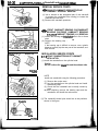
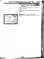
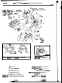
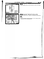
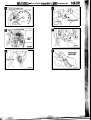
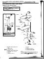
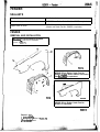
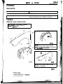
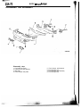
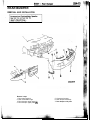
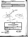
1
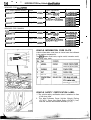
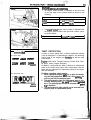
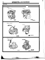
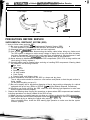
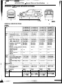
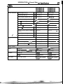
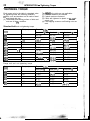
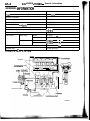
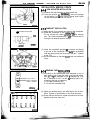
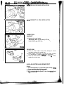
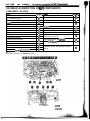
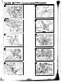
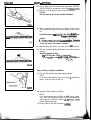
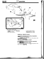
Part ia 1’ 13A~CeKUP
Servicq ~Manual
Engine . . . .:I
::L
.’
This Service Manual ‘has been prepared with the
latest service informatlon available at the time
of publication. It t is subdivided into various group
categories andeach section contains diagnostic,
disassembly, repair,” and instatjation procedures
along with complete specificatiohs and tightening
references. Use of thismanual will aid-,in properly!?
performing any servicing necessary to,maintain or
restore the high levels of performance and reliability
designed into these outstanding vehicles.
I
Rear Suspen@n- ” -. . . . . . . .:‘i . . . :
,I IN’
.. w..
.......
Steering ........ “,,,.......
This BACKUP DSM manual IS to be used ONLY as a BACKUP. Please DO NOT REDISTRIBUTE
WHOLE SECTIONS. This BACKUP was solq to you under the fact that you do indeed OWN
a GENUINE DSM MANUAL. It CANNOT,,~$onsidered a REPLACEMENT (Unless your original
‘-.$‘,
manual was lost or destroyed.)
Please See README.N or README.HTML for additional Information.
Thank you. [email protected]
.k
Emission Cont@Systems . . . . . . .-
ION
Chrysler Motors Co ration reserves the right to make changes in
design or to make a27.
ions to or improvemqnts in its products without
imposing any obligations upon itself to install them on its products
previously manufactured.
@ lW!5 Mitsubishi Motors
I
VEHICLE IDENTIFICATION
VEHICLE IDENTIFICATION NUMBER--LOCATION
The vehicle identification number (V.1.N) is located on a plate
attached to the left top side of the instrument panel.
VEHICLE
IDENTIFICATION C0b~ .&HART
P L A TE
All vehicle identification numbers contain 17 di$iti. Thti vehicle
number is a code which tells country, make, vehicle type,
!tc.
No.
l//i 1 / \\\\\I*
1 2
3 4 5 6
7 8 91011
*OOLOOOQ
1
2
3
4
5
I
Items
Country
Make
Vehicle type
Others
Line
Contents
4: USA
E: EAGLE
3: Passenger car
A: Drive and passenger air hags
K: TALON <FWD>
L: TALON <AWD,
I
7
8
9
10
11
12
NOTE
* “Check digit” means a single number or letter X used to
verify the accuracy of transcription of Vehicle identification
number.
VEHICLE IDENTIFICATION NUMBER LIST
VEHICLES FOR FEDERAL
V.I.N. (except sequence number)
4E3AK44Y*TE
Brand
Eagle Talon <FWD>
4E3AK54F*TE
Eagle Talon cFWD>
4E3AL54F*TE
Eagle Talon <AWD>
. Modelcode
D31AMNHML4E
D31 AMRHML4E
D32AMNGFL4E
2.0 dms (122.0 cuin.)
[DOHC-MFI-Turbo (4683)] D32AMHGFL4E
Engine displ&ement
2.0 dm3 (122.0 cu.in.)
[DOHC-MFI (42OA)l
I
14
-~
-
"
INTRODUCTION -. Vehicle, jdentifictitjcjti
VEHICLES FOR CALIFORNIA
V.I.N. (except sequence number)
4E3AK44Y’TE
Brand
Eagle Talon <MID>
Engine Displacement
2.0 dm3 (122.0 cu.in.)
[DOHC-MFI (420A)]
Model code
D31AMNHMLSE
D31 AMRHMLSE
4E3AK54F*TE
Eagle Talon <FWD>
2.0 dm3 (122.0 cuin.)
[DOHC-MFI-Turbo (4G63)]
4E3AL54F*TE
Eagle Talon d\Wb
D32AMNGFLSE
D32AMRGFLSE
D33AMNGFLSE
D33AMRGFLSE
Engine Displacement
2.0 dms (122.0 cu.in.)
[DOHC-MFI (420A)]
Model code
2.0 dm3 (122.0 cu.in.)
[DOHC-MFI-Turbo (4663)]
D32AMNGFLS’
D32AMRGFLSE
D33AMNGFLSE
D33AMRGFLSE
VEHICLES FOR CANADA
(except sequence number)
4E3AK44YTE
V.I.N.
Brand
Eagle Talon -SVD>
4E3AK54F*TE
Eagle Talon +WD>
4E3AL54F’TE
Eagle Talon <AWD>
D3l AMNHM.4!&
D31 AMRHMtiE
. /_::
-
’
VEHICLE INFORMATION CODE PLATE
Vehicle information code plate is riveted onto the bulkhead
in the engine compartment.
The place shows model code, engine model, transaxle model,
and body color code.
VEHICLE SAFETY CERTIFICATION LABEL
1. The vehicle safety certification label is attached to face
of left door pillar.
2. This label indicates Gross Vehicle Weight Rating
(G.V.W.R.), Gross Axle Weight Rating (G.A.W.R.) front,
rear and Vehicle Identification Number (V.I.N.).
-
ENGIN~E MODEL STAMPING
1. The engine model number is stamped at the front side
on the top edge of the cylinder block as shown in the
following.
Engine model
Engine displacement
420A
2.0 dm3 (122.0 cu.@.)
4G63
2.0 dm3 (122.0 cu.in.1
2.
The 4G63 or 420A engine serial number is stamped near
the engine model number, and the serial number cycles,
as shown below.
1 Engine serial number
For original parts
.iii2uiw
1
THEFT PROTECTION
Theft pro&ion .label
mF!!!w!
1 AA0201 to W9999
!se!!!EE
rrbnnmrrbnn
OOAO212
For replacement parts
[-i!zszEl
OOAO213
(10000222
In order to protect against theft, a Vehicle Identification Number
(VIN) is stamped in, or attached as a label to, the following
-major parts of the engine and transaxle, as well as main
outer panels:
Engine cylinder block, Transaxle housing. Fender, Door, Quarter panel, Hood, Liftgate, Bumpers
In addition, a theft-protection label is attached to replacement
parts for the body outer panel main components, and the
same data are stamped into replacement parts for the engine
and the transaxle.
Cautions regarding panel repairs:
1. When repainting original parts, do so after first masking the theft-protection label, and, after painting, be
sure to peel off the masking tape.
2. The theft-protection label for replacement parts is covered by masking tape, so.such parts can be painted
as is. The masking tape should be removed after palntlng is finished.
3. The theft-protection label should not be removed from
original parts or replacement parts.
16
INTfiQDt~JJCTION’ r ,Vbhicie 4dentification
LOCATIONS
Target area (A: for original equipment parts, B: for replacement parts)
Engine
<Non-turbo>
<Turbo>
Manual transaxle
<Turbo>
eNdi%turbot
A
oO”oo1.
00003678
00x0092
Automatic transaxle
<Non-turbo>
6
<Turbo>
100 mm
WOO3679
ooA0.t~
Target area (A: for original equipment parts, B: for replacement parts)
Fender
Door
31x0521
The illustraticn~indic&s !qfl- hand side, outer.
Right hand side is symmetrically opposite.
Quarter panel
\’
00003660
‘. 3
., ,. / ,5 ,’
The label is attached at the inner ”
‘-,.
side of the parts shown in the figure.
,i’., ;, i :
“. . i
I’
iI
t
The illustration indicates right hand side, outer.
Left hand side is symmetrically opposite.
Hood
Liftgate
6
,: A
31xo4ra
00003661
INTRODUCTION.+y Vehicle I&#tification/Ptie,@autipw before Service
~~
’
Target area (A: for original equipment parts, B: for replacement parts)
Front bumper
Rear bumper
00003662
00X0016
PRECAUTIONS BEFORE SERVICE
SUPPLEMENTAL RESTRAINT SYSTEM (SRS)
1. Items to follow when servicing SRS
(1) Be sure to read GROUP 238 - Supplemental Restraint System (SRS).
For safe operations, please follow the directions and heed all warnings.
(2) Always r&e the <designated special tools and test equipment.
(3) Wait at least 80 seconds after disconnecting the battery cable before doing any further work.
The SRS system is designed to retain enough voltage to deploy the air bag even after the battery
has been disconnected. Serious injury may result from unintended air bag deployment if work
is done on the SRS system .immediately after the battery cable is disconnected.
(4) Never attempt to disassemble or repair the SRS components (SRS- ECU air bag module and
clock spring). If faulty, replace it.
(5) Warning labels must be heeded when servicing or handling SRS components. Warning labels
are located in the following locations.
0 Sun visor
l Glove box
l SRS - ECU
l Steering wheel
l Air bag module
l Clock spring
l Steering gear and linkage clamp
(6) Store components removed from the SRS in a clean and dry place.
The air bag module should be stored on a flat surface and placed so that the pad surface is
facing upward.
Do not place anything on top of it.
(7) Be sure to deploy the air bag before disposing of the air bag module or disposing of a vehicle
equipped with an air bag. (Refer to GROUP 238 - Air Bag Module Disposal Procedures.)
(8) Whenever you finish servicing the SRS, check the SRS warning light operation to make sure
that the system functions properly.
2. Observe the following when carrying out operations on places where SRS components are installed,
including operations not directly related to the SRS air bag.
(1) When removing or installing parts do not allow any impact or shock to the SRS components.
(2) SRS components should not be subjected to heat over 93°C (200°F), so remove the SRS components before drying or baking the vehicle after painting.
After re-installing them, check the SRS warning light operation to make sure that the system
functions properly.
t:
26
INTRODUCTION - General Data and Specifications
”
GENERAL DATA AND SPECIFICATIONS
00x01073
_
GENERAL SPECIFICATIONS
-,
<FWD>
I
Fuel
system
Fuel supply system
Electronically
Electronically
controlled multi- controlled multiport fuel injecport fuel injection
tion
Electronically
Electronically
controlled multi- controlled multiport fuel injection
port fuel inject i o n
27
INTRODUCTION - General Data atl;d”Spe&fkations
<AWD>
Items
Vehicle dimensions
2 1,745 (68.7)
1,745 (68.7)
Overall height (unladen) mm (in.)
3 1,310 (51.6)
1,31 O-(51.6)
Wheelbase mm (in.)
4 2,510 (98.8)
2,510 (98.8)
Tread - Front mm (in.)
7 5
1,5 15 (59.6)
1,515 (59.6)
Tread - Rear mm (in.)
6
1,510 (59.4)
i ,a 0 (59.4)
-~-~-~T ~~ 930 (36.6)
8 935 (36.8)
Transaxle
Fuel system
145 (5.7)
930
(36.6)
.I-.
;
935 (36.8)
145 (5.7)
Angle of approach degrees
10 12.2
12.2
Angle of departure degrees
11 16.2
16.2
”
Curb weights
1,420 (3,130)
1,455 (3,208)
Gross vehicle weight rating
1,850 (4,079)
1,850 (4,079)
Gross axle weight rating -,Front
1,050 (2,315)
1,050 (2,315)
Gross axle weight rating - Rear
850 (1,874)
850 (1,874)
4
4
Model No.
4663 (DOHC)
4G63 (DOHC)
Piston displacement ems (cuin.)
1997 (121.9)
1997 (121.9)
Model No.
W5M33
W4A33
Type
5-speed manual
4-speed automatic
Fuel supply system
Electronically controlled
multiport fuel injection
Electronically controlled
multiport fuel injection
Seating capacity
Engine
4,375 (172.2)
Overall width mm (in.)
Minimum running ground clearance 9
mm (in.)
Vehicle weight kg
(Ibs.)
4,375 (172.2)
1
Overhang - Rear mm (in.)
’
D33AMRGFL4E
D33AMRGFLSE
D33AMRGFLSE
Overall length mm (in.)
Overhang - Front mm (in.)
i.”
D33AMNGFL4E
D33AMNGFLSE
D33AMNGFL5E
._
“-
28
INTRODUCTION - Tightening Torque
TIGHTENING TORQUE
Each torque value in the table is a standard value
for tightening under the following conditions.
(1) Bolts, nuts and washers are all made of steel
and plated with zinc.
(2) The threads and bearing surface of bolts and
nuts are all in dry condition.
The values, in the table are not applicable:
(1) If toothed washers are inserted.
(2) If plastic parts are fastened.
(3) If bolts are tightened to plastic or diecast inserted nuts.
(4) If self-tapping screws or self-locking nuts are
used.
Standard bolt and nut tightening torque
Pitch (mm)
Bolt nominal diameter
(mm)
Torque Nm (ft.lbs.)
Head mark “4”
M5
I
0.8
M6
1.0
Ml0
1.25
Ml2
Ml4
1.25
1.5
I
2.5 (1.8)
I
4.9 (3.6)
1 12(8.7)
24 (17)
Head mark “8”
4.9 (3.6)
I
1 8.8(6.5)
9.8 (7.2)
1 22 (16)
1 25 (18)
44 (33)
52 (38)
8i' (60)
96(71)
137(101)
157(116)
41 (30)
72 (53)
I
I
5.9 (4.3)
1.5
111 (82)
206 (152)
235 (174)
'1.5
167(123)
343 (253)
M20
M22
1.5
1.5
226 (166)
304 (.224)
304 (224)
412 (304)
559(412)
481 (354)
647 (477)
M24
1.5
392 (289)
735(542)
853 (629)
Ml6
Ml8
q 1
I
Head mark ‘7”
:
'. .'
Flange bolt and nut tightening torque
Pitch (mm)
Bolt nominal diameter
(mm)
Torque Nm (ft.lbs.)
I
I
Head mark “4
1 Head mark “7”
I
Head mark ‘8’
L
12 (8.7)
M6
M8
Ml0
1.0
1.25
1.25
4.9 (3.6)
13 (9.4)
26 (19)
9.8 (7.2)
24(17)
49 (36)
28 (20)
57 (42)
Ml0
1.5
24 (17)
44 (33)
54 (40)
Ml2
1.25
46 (34)
93 (69)
Ml2
1 1.75
1 42(31)
) 81 (60)
103 (76)
I96(71)
I
-t
2.OL ENGINE
<TURBO>
CONTENiS
CAMSHAFT AND CAMSHAFT OIL
SEAL . . . . . . . . . . . . . . . . . . . . . . . . . . . . . . . . .
CAMSHAFT AND ROCKER ARMS . . . . . .
CRANKSHAFT, FLYWHEEL, DRIVE
PLATE AND CYLINDER BLOCK . . . . . . . .
CRANKSHAFT FRONT OIL SEAL . . . . . .
CRANKYAFT PULLEY . . . . . . . . . . . . . . . .
CRANKSHAFT: REAR OIL SEAL . . . . . . .
CYLINDER HEAD AND VALVE . . . . . . . . .
CYLINDER HEAD GASKET . . . . . . . . . . . .
ENGINE ASSEMBLY . . . . . . . . . . . . . . . . . . .
ENGINE MOUNTING . . . . . . . . . . . . . . . . . . .
ENGINE ROLL STOPPER . . . . . . . . . . . . . .
ENGINE OIL COOLER . . . . . . . . . . . . . . . . .
29
50
73
34
28
35
54
37
23
19
22
79
.2
GENERAL INFORMATION . . . . . . . . . . . . . . .
OIL PAN AND OIL SCREEN . . . . . . . . . . . 32
OIL PAN, OIL PUMP AND
COUNTERBALANCE SHAFT . . . . . . . . . . . 59
PISTON AND CONNECTING ROD . . . . . . 87
S~AtiNkS . . . . . . . . . . . . . . . . . . . . . . . . . . . . . . 5
ON-VEHICLE SERVICE . . . . . . . . . . . . . . . 10
Basic Idle Speed Adjustment
. . . . . . . . . . . . . . . . . . . . . . Refer to GROUP 14A
Compression Pressure Check . . . . . . . . . . . . . 14
Curb Idle Speed Check . . . . . . . . . . . . . . . . . . . 13
Drive Belt Tension Check and
Adjustment . . . . . . . . . . . . . . . . . . . . . . . . . . . . . . 10
Idle Mixture Check . . . . . . . . . . . . . . . . . . . . . . . 14
Ignition ‘Timing Check . . . . . . . . . . . . . . . . . . . . . 12
.: lash Adjuster Check . . . . . . . . . . . . . . . . . . . . . 16
Manifold Vacuum Check . . . . . . . . . . . . . . . . . . 16
SERVICE SPECIFICATIONS . . . . . . . . . . . . .
SPECIAL TOOLS . . . . . . . . . . . . . . . . . . . . . . .
TIMING BELT . . . . . . . . . . . . . . . . . . . . . . . . .
TIMING BELT B . . . . . . . . . . . . . . . . . . . . . . .
.3
.5
42
47
TRANSAXLE MOUNTING . . . . . . . . . . . . . . 20
TROUBLESHOOTING . . . . . . . . . . . . . . . . . . . .9
9Am2
2.OL ENGINE <TURBO> - General Information
GENERAL INFORMAtION
Items
Specifications
Type
Number of cylinders
In-line OHV, DOHC
4
Bore mm (in.)
85.0 (3.35)
Stroke mm (in.)
88.0 (3.46)
Piston displacement cm3 (cu.in.)
1,997 (121.9)
Compression ratio
8.5
Firing order
l-3-4-2
Counterbalance shaft
Equipped
Valve timing
Intake valve
Exhaust valve
Lubrication system
Opens
21 “BTDC
Closes
Opens
51 “ABDC
57”BBDC
Closes
15”ATDC
”
.
y
I;,.
- , ;
Pressure feed-full floGr filtration
Involute gear type
Oil pump type
i’
c
LUBRICATION SYSTEM
Camshaft
Counte~alance shaft
Oil jet
w
2.OL ENGINE <TURBO, L .Setiice Specifications
SERVICE SPECIFICATIONS
Items
Tension NN (Ibs.)
(tbs.) When checked
Drive belt
(For generator)
When a new belt is installed
When a used belt is installed
Deflection
1 When checked
mm (in.)
When a new belt is installed
<Reference
When a used belt is installed
value>
Drive belt
(For power
steering pump)
1 Standard
Standard value
1
245 - 490 (55.1 - 110.2)
490-686 (110.2 -154.3)
392 (88.2)
I 9.0-11.5(.35-&j)
(
LimitLimit
-
I
-
Drive belt
(For A/C
compressor)
When a used belt is installed
asic ignition timing at idle
ctual ianition timina at idle
:
CIU liui llGll13 -70
HC contents ppm
Compression pressure (at 250 - 400 r/min: 1 kPa (psi)
Compression pressure difference of all cylinder kPa (psi)
Intake manifold vacuum kPa (in.Hg)
Installation dimension of front roll stoboer
. , bracket assemblv mm (in.)
Auto ._.._
tensioner
____
- - oush
,~ rod movement mm (in.)
Timing belt tension torque Nm (ft.lbs)
. ’
r
rod
mm
protrusion
(in.)
Auto tensioner
mm
Timingbell 6 tension
~~
. (in.).
Cam height (Intake) mm (in.)
Camshaft
Cam height (Exhaust) mm (in.)
II Journal diameter mm (in.)
Cylinder head 1 Flatness of gasket surface mm (in.)
Grinding limit of gasket surface
Includes/combined with cylinder block grinding mm
(in.)
Overall height mm (in.)
1 6.5-7.5 (.26-.30)
1 5”BTDC f 3”’
1 Approx. 8: E 3TQc
(750flf IO . ..” ::!*;,
1 0.5 or less+: I- .- 31’i. , ‘:f
.-- orless
.
lw
:: .I -,.: :
1250 (178)
-1 -1
min. 935 (133)
max. 1OP 1141
min. 60 (18)
I \r.,
43f3(1.69&.12)
I\rMthin
-------- 1 1.041
\-#
1 3.5(2.6)
1 3.8 - 4.5 (.l. 50--177)
1 5 - 7 (.20-A !8).
34.91 (1.3744)
34.91 p79f.
(1 .oiioi
- ,~-.i~ ,
12-5.96
1 0.05 (,902a;>T\
..
-
34.41 (1.3547)
34.41 (1.3547)
,
1 0.2- _(.008)
.-_
l
Oversize valve guide hole (both intake and exhaust)
0.05 O.S. mm (in.)
Oversize valve guide hole (both intake and exhaust)
0.25 O.S. mm (in.)
Oversize valve guide hole (both intake and exhaust)
0.50 O.S. mm (in.)
131.9-132.1
(5.91 - 5.20)
12.05 - 12.97
(.4744-.4752)
12.25 - 12.27
(.48234831)
12.50 - 12.52
(.4921 - &?9)
-
3)
I
I
Items
Cylinder head
35JO i 35.33 (1.3898 - 1.3909) -; .’ .I,
35.60 -~35.63 (MI1 6 -- 1.4028)
Oversize exiiaust valve &at &g hole
fl3r-r n ,S -mm-h \
. ,L . ,. . ..I... ”
I
33.30-.33,33 (1.3110- 1.3122)
I,
!
:,
I
1 .“’ .:’
.‘,. ‘:
-
.Cytjnder head bolt
Val\ie
”
:I
Valve sprin .+
i!
(It%:)/ iini. (in.)
I ” “*
245 (54)/4-0.0 (1.57)
Valve seat
Valve
. . guide ,
: .,
Oij +I@.
Prbje&@r+dr
s-.~i-.~.-ti.~ii
Side clearance
9.96N39.!4 (9031
0.06 - 0.12 LO024
78 (11.4).or more
Piston
Piston ring
Connecting rod ‘.
Crankshaft
?l)
0.4 (.016)
. 0 . 2 5 LOO98)
Cyljnder bl&
,F’-‘i , 1,1 , T o.oq (.qQ12 - .0020)
Flatness of gasket surface mm~(iri?)~~!i:~!~AI~ ;I ;O.OS (.0020) i
J
Includes/combined with cylinder block: I’/, ‘d
‘.,,’
.I
arindina mm (in.)
/I
I
Cverallheight mm (in.)
j 283.9-284.1 (11.177-11.185)‘
Inner diameter mm (in.)
85.0 (3.348)
- Cylindricity mm,(in.)
l
SerIiici6%ifai packing and rocker cover
:
‘..,
. j
i$.; ; ;- y$: , .:
:
,
;:?., A
:
. . ~
,.
i’ f $
It
.MITSUBISHI GENUINE PART MD970389 or equivalent
Oil pan, cyliper bloc$ and thermostat case
assembly
_.. _
t&w oil.Seal case : :
_
,.,._ 4 _-.,__; . . . -‘I
Flywheel bolt or dV&e~pt,ate.bo;a !. i
-'I
._ ..I
._
431803!,~~~~~~~~~r,equiv~l~~t_~, .,,, ;?;‘&&.r”~ ”
.!, ;""l'$y:“i
I' ‘
i$
f
iPEClAL TOOLS
:-
Tool number and nan@
$%@a&d b y M i l l e r *j Application
toothumber
MB991 502
DRB-III Scan tool
Scan tool
(MUT-II)
MD998713
i, , ;_
A’
‘l
Oil pressure gauge unit
(..;sr;$sp-,‘&y .’ :.:.> ,,.,
Oil pressure switch
_.
l
MCPAfj~Par$oX31803+or equivalent
Bearing cap (front, rear) and cylinder head
TooI
0.1 (.004)
0.2 (408)
"
1
; ii;
TV., ..__
f
I idle speed inspection’
;;;- ::
I L
...
‘;t
.’
Camshaft oil seal
-in ajler-- . _ _ .._. .--.-.:w
t:.:$qi
$;a
@iT?e 1 i ,$
,r’l-‘i- 1.,
.I
/
:.*-,
,?
. . ,,
,.. I/
,General service tool ““’ “’
(Use scraper and
excerci$e care)
Oil pan gasket cutter
. ._
. _ . ._c- -._. *i* ^.. -&-...i -.... I. . . . _.__._.
,; ;: 3. :?I
: .‘.
,i
,.
_ $$&.:IJ
MD998727
.
^
..-,.
I__.-__:..
.-
_...
.._--__.,
1
.I.,^
,
,_
_
:
I
..,. .-._” ____,,,
A’I
*... _ .-,. _. - --..-y--“,
.I_
.I
Tool number and nami
MD998781
Flywheel stopper
MD998778
Crankshaft rear oil
seal installer
MB990938
~-----
Handle
GENERAL SERVICE
TOOL
MZ203827
Engine litter
MB991 453
‘En$&th;anger
assembly
.
-.
MD998767 I : -:~&~~~~~~ ,+to ;tensioner installation
MD998767
Tensioner pulley
wrench
MD998778
Crankshaft sprocket
puller
MD998782
Valve litter :< set
Ii
I+:.?
MB990767
End yoke holder
,,
: :,
_
..-
_
.
.
,I.
b._ ,... . . . _. “.
(,.,,.
Tool’number
_di.L_ /- and name
I
Ml$9:j193
.,
Replaced by Miller
tool number
General service tool
(Use shop towel)
$@vehting for&in substances
fro’m; riteri$transfer
~$vJl 6
,j ,;,
Plug
‘MD9981 62
MD9981 62
PI& wrench
,_
,‘i
MD998285
i-”:3-.
lM~9$8;05
..,,:i,._
Silent shaft bearing
installer
(for front and rear
bearihgs) !
MD998373
‘. ,/:
MB991 603
‘,.’
&l&it shaft bearing
,stopper
MB991 603
MD998375
C-3095-A
,..,. * ‘1
--.-x~toppetifo~ use iti iemoval
I. /. *:.
Crankshaft front oil seal installa: y. 4, ,:, * ,
tion
“.
Crankshaft front oil
seal installer
:
MD998371
.d
._
.
‘Zotiirterbalanceshaft front bear,itig removal
MD998371
;;X$ shaft bearing
,.
I-)
MD998372
Silent shaft bearing
puller
MD998440
Leak-down tester
MD998372
‘Counterbalance shaft rear bearing removal
,’ (U&d with MB991 603)
. Leakdown ted of lash adjuster
ioifi
Application
Air bleeding of auto lasl’~ adj@W
/ .I
.>:,2, ,I
!
.
. .-..
‘,.,.,! t
r
_
,i.
.
_
/
II
.
‘I
!
i
, ’
,-.
.,
:
..- ,,,...
SW-28
2.OL ENGINE <TURBO> - CrankdibfttPirlf@
CRANKSHAFT PULLEY
REMOVAL AND INSTALLATION
s
Pre-removal Operation
Under Cover Removal
(Refer to GROUP 23A - Under Cover.)
l
AOlX0179
Removal steps
1. Drive belt (Generator)
2. Drive belt (Power steering)
3. Drive belt (A/C)
4. Crankshaft pulley
CAMSHAFT AND CAMSHAFT OIL SEAL
REMOVAL AND INSTALLATION
h
Pm-removal Operation
Timing Belt Front Upper Cover Removal
(Refer to P.QA-42.)
Timing Belt Front Upper Cover Installation
l
2.9 Nm
2.2 Fibs.
3
bs.
16
4.9 Nm
3.6 ft.lbs.
OlNOO42
Engine oil
6
OJAOO46
Cylinder head
Specified sealant: MOPAR Part No. 4318034 or equivalent
Removal steps
1. Accelerator cable connection
2. Center cover
3. Spark plug cable
4. Breather hose
5. PCV hose
6. Rocker cover
7. Timing belt (Refer to P.9A-42.)
8. Exhaust camshaft sprocket
9. Intake camshaft sprocket
10. Front camshaft bearing cap
11. Camshaft bearing cap
12. Rear camshaft bearing cap (R.H.)
13. Rear camshaft bearing cap (L.H.)
14. Exhaust camshaft
15. Intake camshaft
16. Camshaft oil seal
17. Semicircular packing
Installation steps
.A+ 15. Intake camshaft
,A+ 14. Exhaust camshaft
FBI 13. Rear camshaft bearing cap (R.H.)
.B+ 12. Rear camshaft bearing cap (L.H.)
FBI 11. Camshaft beating cap
bB+ 10. Front camshaft bearing cap
bC+ 16. Camshaft oil seal
9. Intake camshaft sprocket
8. Exhaust camshaft sprocket
7. Timing belt (Refer to P.9A-42.)
17. Semi-circular packing
6. Rocker cover
5. PCV hose
4. Breather hose
3. Spark plug cable
2. Center cover
1. Accelerator cat?@ cqn ection
(Refer to GROUP 14P‘II On-vetiicle Service.), ,_, -I
9A-30
2.0L ENGINE GURBO~ + Camshaft and Uimshaft ‘Oil S&l:
r
REMOVAL SERVICE POINTS
dA, EXHAUST CAMSHAFT SPROCKET/INTAKE
CAMSHAFT SPROCKET REMOVAL
(1) Use a wrench at the hexagonal part of the camshaft
(to prevent the crankshaft from turning) to loosen the
camshaft sprocket bolt.
(2) Remove the camshaft sprockets.
46, FRONT CAMSHAFT BEARING CAP/CAMSHAFT
BEARING CAP/REAR CAMSHAFT BEARING
(R.H.)/REAR CAMSHAFT FEARING (L.H.) REMOVAL
Plastic hammer
(1) Loosen the bearing cap installati& bolts in two or three
steps.
(2) Remove the bearing cap. ..
-NOTE
If the bearing cap is difficult to remove, use a plastic
hammer to gently tap the rear part of the camshaft, and
then remove.
Intake s i d e if
Exhaust side
I
INSTALLATION SERVICE POINTS
.A+ INTAKE CAMSHAFT/EXHAUST CAMSHAFT
INSTALLATION
(1) Install the camshafts on the cylinder head.
Caution
Do not confuse the Intake side and the exhaust side.
Slits
01 A0048 I
NOTE
Install new camshafts using the following procedure.
(1) Remove the rocker arms.
(2) Lay the camshafts on the cylinder head and install
the bearing caps.
(3) Check that the camshaft can be easily turned by
hand.
(4) After checking, remove the bearing caps and the
camshafts, and install the rocker arms.
Dowel tins
Exhaust side
intake side
*ol*oow
(2) The camshaft’s dowel pins should be at the positions
shown in the figure.
2.OL ENGINE <TURBO* - i=amsf&Wand Camtihtift Oil &al
,Bq REAR CAMSHAFT BEARING CAP (R.H$REAR
CAMSHAFT BEARING CAP (L&.)/CAMSHAFT
BEARING CAP/FROM CAMSHAFT BEARING CAP
INSTALLATION
Tighten the bearing cap installation bolts to the specified torque
in two or three steps.
Caution
Tighten uniformly, otherwise the rocker arms will not be
straight.
,C+ CAMSHAFT OIL SEAL INSTALLATION
Use the special tool to drive the camshaft oil seal into position
carefully.
2.OL ENGINE .4tIJRBO~ i -CjjlffiZfer !Hi%d Gasket
CYLINDER HEAD GASKET
REMOVAL AND INSTALLATION
1
Pm-removal Operation
l Fuel Line inner Pressure Release
(Refer to GROUP 14A-On-vehicle Service.)
l Engine Coolant Draining
(Refer to GROUP O-Maintenance Service.)
l Engine Oil Draining
(Refer to GROUP O-Maintenance Service.)
I
J
I
I
I
Post-installation Operation
l Engine Oil Refilling
(Refer to GROUP O-Maintenance Service.)
l Engine Coolant Refillin
(Refer to GROUP 0- 9aintenance Service.)
4.9
- - -.Nm
..
2.9 Nm
,?w
1
18
8
12 -r65/
-2
ii!%- 25
21'
&ing
OJAOO70
Engine oil
01x0199
Removal steps ”
1. Accelerator cable connection
$Iyfi;ot; GROUP 14F-On-vehicle
2. Air hose C
3. Idle air control motor connector
4. Knock sensor connector
5. Heated oxygen sensor connector
6. Engine coolant temperature gauge
unit connector
7. Engine coolant temperature sensor
connector
8. Ignition power transistor connector
9. Throttle. position sensor connector
10. Capacitor connector
11. Manifold’ differential pressure
sensor connector
12. Injector;,connectors
13. tgnition icoil connector
14. Camshaft position sensor connector
15. Crankshaft position sensor
connector
16. Air conditioning compressor
connector
17. Control wiring harness
18. Center cover
19. Spark plug cable
20. Brake booster vacuum hose
connection
FE+ 21. High-pressure fuel hose connection
22. Fuel return hose connection
23. B -pass valve hose connection
24. VY
ater hose connection
25. Vacuum “hoses connection
26. Breather;hose connection
27:. RX h o s e .connection
,., .,!, a’:., < :; /,
‘, .,
2.OL- ENGINE <TURBO> - Cylinder Head Gasket
q
12-15 Nm
<Cold en ine>
38.(
76 Nm-,, 8Nm+20 N m 8-7-11ftA
++90” -++90”
11
I A
(58 ft.lbs.+O Ribs.+15 ft.lbs.
a
++90” ++90”)
\
“I/ -
/34 3 6
-34 Nm
-25 ft.lbs.
Cylinder head
Sealant: MOPAR Part No. 4318034 or equivalent
0 Timing belt
(Refer to P.9A-42.)
28. Power steering pump
29. Rocker cover
30. Semicircular packing
31. Heat protector (A)
32. Water hose connection
33. Water hose A connection
4A, ,Ed 34. Radiator upper hose ‘connection
qA, ,Ed 35. Radiator lower hose connection
01x0174
&eclfled sealant:
MITSUBISHI GENUINE PART
MD970389 or equivalent
LM ;I. ;h,enx$ostat case assembly
38: Flange bolts and flange nut
(Refer to GROUP ll-Exhaust
Manifold and Turbocharger.)
.B+ 39. Cylinder head bolt
t. $$der head assembly
42: Gasket (A) .- 1:. :
.A4 43. Cylinder head,Qask;et
.C( CRANKSHAFT SENSING BLADE INSTALLATION
Crankshaft
sensing blade
When installing, make sure the direction is correct. See figure.
AOlXO201
.D+ CRANKSHAFT SPROCKET INSTALLATION
Use the special tool to install the crankshaft sprocket and
bolt.
NOTE
Apply the minimum amount of-engine oil to the bearing surface
and thread of the crankshaft bolt.
AllAOllO
9A950
2.0L ENGINE ;clTlJRBO,~ 3Mishaft and Rock& Arms
CAMSHAFT AND ROCKER ARMS
REMOVAL AND INSTALLATION
& Lubricate all
internal parts
with engine oil
I during reassembly.
t’
11 I
12
6ENl079
FE+
.D+
bC+
W+
Wq
bCi4
Removal steps
1. Plate
2. Camshaft oil seal
3. Circular packing
4. Bearing cap front
5. Bearing cap rear
6. Bearing cap No. 2
7. Bearing cap No. 5
,C+ 8. Bearing cap No. 3
.C+ 9. Bearing cap No. 4
,B+ 10. Camshaft
11. Rocker arm
.A+ 12. Lash adjuster .
13. Oil delivery body
INSTALLATION SERVICE POINTS
,A4 LASH ADJUSTER INSTALLATION
(1) Immerse the lash adjuster in clean diesel fuel.
(2) Using the special tool (MD998442), move the plunger
up and down 4 or 5 times while pushing down lightly
on the check ball to bleed out the air.
atNO
.Bq CAMSHAFT INSTALLATION
C Camshaft sprocket side
W’ S’it
(1) Apply engine oil to journals and cams of the camshafts.
(2) Install the camshafts on the cylfnder.head.
Do not confuse the intake’ camshaft’:with the exhaust
one. The intake camshaft has a slit on its rear end for
driving the crankshaft position sensor.
intake side
t’
Dowel
(3) Install the crankshaft sprocket B or spacer and flange
to an end of the crankshaft. Then turn the crankshaft
until the timing marks are lined up to set No.? cylinder
to the TDC.
(4) Set the camshafts so that their dowel. pins are positioned
at top.
:
pin
.Cq BEARING CAPS INSTALLATION
04
LF
Capnumber
Symbol identifying
intake or exhaust
Lu
(1) According to the identification mark stamped on top of
each bearing cap, install the caps to the cylinder head.
Only “L” or “R” is stamped on No. 1 bearing cap. Cap
No. is stamped on No. 2 to No. 5 bearing caps, No.
6 bearing cap has no stamping.
I: For intake camshaft side
E: For exhaust camshaft side
6EN0464
W
11
53
Camshaft sprocket side
9
7
12
8
10
12
48
6EN0192
(2) Tighten the bearing caps in the order shown two to three
times. Tighten to specification in the final sequence.
(3) Check that the rocker arm is held in position on the lash
adjuster and valve stem end.
2.OL ENGINE <TURBO>-- CamshMtiatid Robket Arms’
MD99871 3
I
r
,D+ CIRCULAR PACKING INSTALLATION
.E+ CAMSHAFT OIL SEAL INSTALLATION
INSPECTION
CAMSHAFT
(1) Measure the cam height.
Standard value: 34.91 mm (1.37 in.) .,
Limit’: 34.51 mm (1.35 in.)
9ENOO58
ROCKER ARM
(1) Check the roller surface. If any dents, damage or seizure
is evident, replace the rocker arm.
(2) Check rotation of the roller. If it does not rotate smoothly
or if looseness is evident, replace the rocker arm.
(3) Check the inside diameter. If damage or seizure ,is evident,
replace the rocker arm.
6ENOl85
LASH ADJUSTER LEAK DOWN TEST
Caution
1. The lash adjuster is a precision part. Keep ‘it free
from dust and other foreign matter.
2. Do not disassemble lash adjuster.
3. When cleaning lash adjuster, use clean dies+ fuel
only.
2.OL, ENGINE <TURBGs - CatidhMt?iih&RBcker Mms
6ENO421
S&!ifs
(1) Immerse the lash adjuster in clean diesel fuel.
(2) While lightly pushing down inner steel ball using the special
tool (MD998442), move the plunger up and down four
or five times to bleed air.
Use of the retainer helps the air bleeding of the rocker
arm mounted type lash adjuster.
(3) Remove the small wire and press the plunger. If the
plunger is hard to be pushed in, the lash adjuster is normal.
If the plunger can be pushed in all the way readily, bleed
the lash adjuster again and test again. If the plunger
is still loose, replace the lash adjuster.
Caution
Immediately after air bleeding, hold lash adjuster up
right to prevent fuel from spilling.
1’ Division = 1 mm LO39 in.1
(4) After air bleeding, set lash adjuster on the special tool
(Leak down tester MD998440).
(5) After plunger has gone down 0.2 to 0.5 mm (908 to
.020 in.), measure time taken for it to go down 1 mm
MD99
L (.039 in.). Replace if measured time is out of specification.
Standard value: 4-20 seconds/l mm (.04 in.)
[Diesel fuel at M-20’% (59~68”F)j
7ENO438
Soale = 1 mm (.039 in.)
MD9W40
1,l-l
Lash
adjuster
2.OL -ENGINE <TURBO> - CylintW He& ti&$Val\ie -
CYLINDER HEAD AND VALVE
REMOVAL AND INSTALLATION
I
all internal
:m’1 Lubricate
parts with engine oil
during reassembly.
I
6EN0948
Removal steps
a, .C+ 1. Cyljnder head bolt
;. C&knkrn head assembly
.B+ 4: Retainer lock
5. Valve spring retainer
6. Valve spring
7. Intake valve
4W
.B+ 8. Retainer lock
9. Valve spring retainer
IO. Valve spring
11. Exhaust valve
,A+ 12. Valve stem seal
13. Valve spring seat
+C, .A+ 14. Valve stem seal
15. Valve sprin,g seat
16. Intake valve guide
17. Exhaust valve guide
18. Intake valve seat
19. Exhaust valve seat
20. Cylinder head
r _‘, . . .
1::
ON-VEHICLE INSPECTION OF MFI COMPONENTS
COMPONENT LOCATION
Name
Air conditioning compressor clutch relay
Air conditioning switch
Camshaft position sensor
Check engine/Malfunction indicator lamp
Crankshaft position sensor
Data link connector
EGR solenoid
Engine control module (ECM)
Engine coolant temperature sensor
Evaporative emission purge solenoid
Fuel pressure solenoid
Fuel pump check terminal
Fuel pump relay
Heated oxygen sensor (Front)
Heated oxygen sensor (Rear)
Idle air control motor
Ignition coil (IgnitiQh powentransistor)
\>ylll”“l
A
W
N
U
0
V
J
X
D
J
M
E
Y
Q
2
F
K
,“a I Ici
Ignition timing adjustment connector
Injector
Knock sensor
Manifold differential pressure (MDP) sensor
“J”‘LN’
E
R
L
Multiport fuel injection (MFI) relay
Park/Neutral position switch
Power steering pressure switch
Resistor
Throttle position sensor (with built-in closed
throttle position switch)
Y
T
P
I
G
Turbocharger waste gate sol8noid
Vehicle speed sensor
S
C
Volume air flow sensor (with built-in intake air
temperature sensor and barometric pressure
sensor)
B
NOTE
The “Name” column is in alphabetical order.
6FU2077
6FU2078
6FU248o
H
MFI, <TURBO>.“L On-vehicle Inspectbn of MFI C&ii~ier;i@i ’
‘f’#sesg
. *
-I
//L
Idle air control motor, (stepper motor)
14A-240
MFI <TURBO>. 9’. On-vehici~~;In’specti~n of MFI ;CiirQYdneri& ”
Intake side
camshaft
sprocket
MFI <TURBO> - On-vehicle: ins@dtik;~6f .-MFi Components
l&j#3&l
14F-10 FUEL SUPPLY AND ENGINE CONTROL - Accelerator Cable And P&M
ACCELERATOR CABLE AND ~-PEDAL
GENERAL INFORMATION
A cable-type accelerator mechanism and a
suspended-type pedal have been adopted.
SERVICE SPECIFICATION
Item
Standard value
Accelerator cable play mm (in.)
l-2 (.04-.08)
LUBRICANT
Item
Specified lubricant
Quantity
Accelerator pedal pin, spring
accelerator cable end
MOPAR Multi-mileage Lubricant Part
No. 2525035 or equivalent
As required
TROUBLESHOOTING
Symptom
Throttle valve will not
fully open or close
Accelerator pedal operation not smooth
(over acceleration)
21
3
Probable cause
Remedy
Misadjusted accelerator cable
Adjust
Misadjusted auto-cruise control cable
Adjust
Broken return spring
Replace
Throttle lever malfunction
Replace
Accelerator pedal wrongly tightened
Repair
Misinstalled accelerator cable
Repair
Accelerator cable requires lubrication
Lubricate or replace
;
ON4EHICLE SERVICE
ACCELERiTOR CABLE CHECK AND
ADJUSTMENT
For models equjpped with the auto-cruise control system,
refer to GROUP 14G - On-vehicle Service.
1. Turn AIC and lights OFF.
inspect and adjust at no load.
2. Warm engine until stabilized at idle.
3. Confirm idle speed is at prescribed rpm.
4. Stop engine (ignition switch OFF).
5. Confirm there are no sharp bends in accelerator cable.
6. Check inner cable for correct slack.
7. If there is too much slack or no slack, adjust play by
the following procedures.
(13:Turn the ignition switch to the ON position (without
starting the engine) and leave in that condition for
.approximately 15 seconds in order to initialize the
IAC motor.
(2) Loosen the adjusting bolt to release the cable.
(3) After moving the plate to the position immediately
before the throttle lever starts to move, move the
plate back towards the throttle body by the standard
value amount only to bring the accelerator cable play
to’ the standard value.
:
Standard value: l-2 mm (.04-.08 in.)
(4) Tighten the adjusting bolts to the specified torque.
4.9 Nm
3.6 Ribs.
dlate
AOlA0021
8. Adjust accelerator cable play and confirm throttle lever
stopper touches the fixed SAS.
i:
(,/.
14F-12 FUEL SUPPLY AND ENGINE CONTROL
‘- iGcelerator &6i’iiCA8d,@&@
ACCELERATOR CABLE AND PEDAL
REMOVAL AND INSTALLATION
Post-Installation Operation
;I$ator*CaMe Adjustment, (Refer to P.l4F-10; for
upped with auto-cruise control system, refer
to GROU
“s14G - On-vehicle Service.)
1
4.9 Nm
3.6ft.lbs.
2
I -
kI
<Turbo>
4.9
3.6
4.9 Nm
3.6hlbs.l
<Non-turbo>
4.9 Nm
3.6ftlbs.
11
/
Grease:
MOPAR Multi-Mileage Lubricant
Part No. 2525035 or equivalent
13 Nm
9.4 ft.lbs.
Nm
3.6ft.lbs.
4.;
Accelerator cable removal steps
1. Clip
2. Adjusting bolts
,A+ 3. Accelerator cable
Accelerator pedal removal steps
4. Accelerator cable connection
5. Cotter pin
6. Washer
7. Accelerator pedal pin
8. Bushing
9. Spring
10. Accelerator pedal arm
11. Accelerator pedal bracket
12. Accelerator pedal stopper
NOTE
For models equipped with auto-cruise control system, the
accelerator cabfe removaVinstallation procedures are
referred to GROUP 14G - Auto-cruise control system.
FUEL SUPPLY AND ENGINE CONTROL - Accelerator Cable And Pedal
14b!'f3
INSTALLATION SERVICE POINT
,A(ACCELERATOR CABLE INSTALLATION <Turbo>
Clamp the accelerator cable so that its marking is as shown.
BODY - Hood
INSTALLATION SERVICE POINT
Bumper
(small)
Bumper
,A4 BUMPER INSTALLATION
Install the bumper as shown in the diagram.
(large) 17 m m
10x0722
18X0721
,’
t**.
00000130
“I
INSPECTION
HOOD SWITCH CONTINUITY CHECK
18X0831
mm (in.)
00000129
r
:
_,
_
,;x.,
FENDER
SEALANTS
I
Items
Specified sealants
Fender to body panel
MOPAR Silicone Rubber Sealer Part No. 4026070 or equivalent
Splash shield to fender
MOPAR Silicone Rubber Sealer Part No. 4026070 or Auto Glass
Adhesive and Sealer Part No. 2298825 or equivalent
I
FENDER
REMOVAL AND INSTALLATION
Prwemoval and post-installation Operation
Front Bum r Removal and Installation
(Refer to ge
.23A-71.)
10x0734
Sealant:
MOPAR Silicon Rubber Sealer Part No.
4026070 or Auto Glass Adhesive and Sealer
Part No.2298825 or equivalent
18X0736
18X0729
Sealant:
MOPAR Silicon Rubber Sealer Part No.
4026070 or equivalent
00000131
Removal steps
1. Splash shield :
l S@e air cjam (Refer to P.23A-79)
i. Front fend& panel
eODY
,,,-
-
Fend&
FENDER
SEALANTS
I t e m s
Specified sealants
I
Fender to body panel
I
Splash shield to fender
I MOPAR Silicone Rubber Sealer Part No. 4026070 or equivalent I
MOPAR Silicone Rubber Sealer Part No. 4026070 or Auto Glass
Adhesive and Sealer Part No. 2298825 or equivalent
FENDER
REMOVAL AND INSTALLATION
Preremoval and post-installation Operation
Front Bum r Renioval and installation
(Refer to B”
.23A-71.)
18X0734
Sealant:
MOPAR Silicon Rubber Sealer Part No.
4026070 or Auto Glass Adhesive and Sealer
Part No.2298825 or equivalent
18X0736
18X0729
Sealant:
MOPAR Silicon Rubber Sealer Part No.
4026070 or equivalent
00000131
Removal steps
1. Splash shield
l Side air dam (Refer to P.23A-79)
2. Front fender panel
g?&p:
*
BODY i Front Bumper
’
FRONT BUMPER
REMOVAL AND INSTALLATION
Prs-removal and Post-installation Operation
S lash shield Removal and Installation
&efer to GROUP 23A-61.)
Removal steps
1. Fog light
2. Front side-marker light
3. Front bumper center plate
4. Front bumper assembly
;. Fc$t bumper corner plate
7: Front fascia bracket
‘!$
23A-72
BODY - Pro’nt Biimper-
DISASSEMBLY AND REASSEMBLY
Disassembly steps
1. Fog light hole cover
2. Front license plate bracket
3. Bolt plate
4. Front bumper side plate
5. Front bumper reinforcement
6. Front bumper core
7. Front bumper stay assembly
8. Front bumper face
REAR BUMPER
REMOVAL AND INSTALLATION
6
~16x0676
Removal steps
1. Rear panel garnish
2. Rear combination light
3. Rear bumper upper plate (A)
4. Rear bumper upper plate (B)
5. Connector harness
6. Rear bumper assembly
7. Rear bumper side plate
BODY<- Rear Burnber
DISASSEMBLY AND REASSEMBLY
Alox1oos
Disassembly steps
1. Rear bumper lower plate
2. Rear bumper reinforcement
3. Rear bumper core
4. Rear bumper stay assembly
5. Rear bumper face
BODY -; ~GarnisheS
GARNISHES
REMOVAL AND INSTALLATION
13Nm
18X0675
00003740
Front deck garnish removal steps
1. Wiper arm assembly
2. Front deck garnish
Rear panel garnish removal steps
l Rear end trim
(Refq to P.$JA-90)
3. Rea? ,-panel garnish
23A-76
BODY, ‘- Moldings
MOLDINGS
SEALANT AND ADHESIVE
Items
Specified sealant and adhesive
Side protector molding
3M ATD Part No. 6382 or equivalent and
3M ATD Part No. 8608 Super Fast Urethane Primer or equivalent
MOLDINGS
REMOVAL AND INSTALLATION
Adhesive tape:
3M ATD Part No. 6382 or equivalent
15 mm (59 in.) wide and 1.2 mm (.047 in.) thick
Adhesive:
3M ATD Part No. 8606 Super Fast Urethane Primer or equivalent
1. Windshield molding
(Refer to P.23A-10)
2. Belt line molding
(Refer to P.23A-50)
+A, .A+ 3. Side protector molding
4. Liftgate molding
(Refer to P.23A-18)
Drip line weatherstrip
(Refer to P.23A-50)
s Door weatherstri holder
(Refer to P.23AJO)
5. Drip molding
l
BODY - Moldings
REMOVAL SERV’ICE POINT
Masking tape
+A, SIDE PROTECTOR MOLDING REMOVAL
(1) Apply masking tape to the outside circumference of the
side protector molding.
Fishing line
\
I
(2) Insert fishing line [0O.8 mm (.03 in.)] in between the body
and the side protector molding, pull both ends alternately
to cut the adhesive section and remove the side protector
molding.
Caution
1. When reusing the side protector Molding, pull the
fishing line along the edge of the body so as not
to damage the edge of the side protector Molding.
2. If the adhesive Is difficult to remove, heat it to
40°C (104°F).
.
Double-sided tape
I
Adhesive
\
(3) Scrape off the double-sided tape with a resin spatula.
(4) Tear off the masking tape;
(5) Scrape off a small amount of the adhesive with a cutter
knife.
Aesin spatula
(6) Use a shop towel moistened with degreaser (MOPAR
SUPER KLEEN or equivalent) to wipe the body surface.
INSTALLATION SERVICE POINT
,A+ SIDE PROTECTOR MOLDING INSTALLATION
Double-sided tap6 affixing to the side protector Molding
(when reusing)
(1) Scrape off the double-sided tape with a resin spatula
or gasket scraper.
BfJDV - MotdtnQs(2) Use a shop towel moistened with degreaser (MOPAR
SUPER KLEEN or equivalent) to wipe the moldingsurface.
(3) Remove a small portion of the residual adhesive.
Caution
Do not remove all of the residual adhesive.
(4) Soak a sponge in the primer, and apply evenly to the
side protector molding in the places shown in the illustration.
Primer
Specified primer: 3M ATD Part No. 8608 Super Fast
Urethane Prim* di’&@G!l~nt
?j ‘!.: 6.
,‘j
,.:: ‘,
.
r
.
Caution
i. Always apply it on the entiie’ I&x%+-because
a lot or little will reduce its strength,
2. Do not touch the coated surface.
(5) After applying the primer, let it dry for 3 to 3g. minutes.
(6) Affix the specified double-sided tape to the side protector
molding.
Specified adhesive tape:
3M ATD Part No. 6382 or equivalenf
15 mm (59 in.) wide and %+~mrn.?#J47&L)~
thick
.* ‘., II* ?..“‘<p+“:,+>
& :i.&$ ”
’ ( ,_ :.
Side protector molding installation
(1) Tear off the double-sided tape backing paper.
NOTE
If you attach the adhesive tape to the edge of the backing
paper, it will be easy to tear off.
Al8XO607
(2) Install the side protector molding.
NOTE
If the double-sided tape is difficult to affix during winter,
etc., warm the bonding surfaces of the body and the
side protector molding to about 40-6O”C (104-140°F)
before affixing the tape.
(3) Firmly press in the side protector -molding.
BODY - Aero Patts
AERO PARTS
SEALANT AND ADHESIVE
I
Items
Specified sealant and adhesive
Door garnish, Side air dam
3M ATD Part No. 6382 or equivalent and
3MATD Part No. 8608 Super Fast Urethane Primer or equivalent
AERO PARTS
REMOVAL AND INSTALLATION
Adhesive tape:
3M ATD Part No. 6382 or equivalent
4 mm (.15 in.) wide and 1.5 mm (.059 in.) thick
Adhesive:
3M ATD Part No. 8608 Super Fast Urethane Primer or equivalent
Door garnish removal
+A, ,A1 1. Door garnish
Side air dam removal steps
BODY * : Awe Paits
18X0673
00003751
nm (in.)
-
10x0133
Rear spoiler removal steps
l
Liftgate lower trim (Refer to P.23A-90)
1. Connector harness
2. Rear spoiler assembly
3. High mounted stop light
4. Dua!-!oc\ fastener (small)
5. Dual-lock fastener (large)
REMOVAL SERVICE POINT
+A, DOOR GARNISH/FRONT SIDE-AIR DAM/REAR
SIDE-AIR DAM REMOVAL
Carry out..@b same procedure as for the side protector moldings. (Refer to P.23A-76.)
INSTALLATION SERVICE POINT
.A+ DOOR GARNISH/FRONT SIDE-AIR DAM/REAR
SIDELAIR DAM INSTALLATION
Carry out the same procedure as for the side protector moldings. (Refer to P.23A-76.)