1
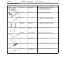
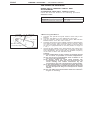
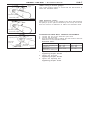
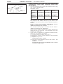
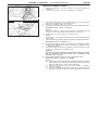
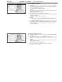
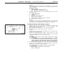
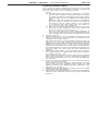
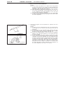
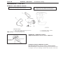
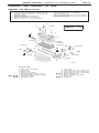
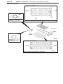
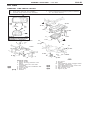
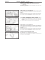
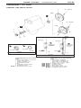
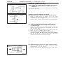
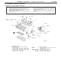
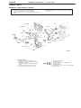
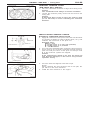
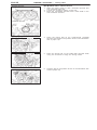
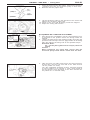
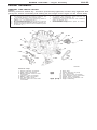
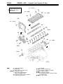
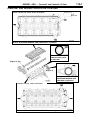
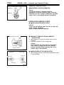
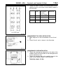
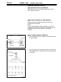
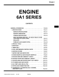
ENGINE
<4G9-GDI>
Click on the applicable bookmark to selected the required model year
11A-1
ENGINE
<4G9-GDI>
CONTENTS
GENERAL INFORMATION . . . . . . . . . . . . . . . . . . 2
Lash Adjuster Check . . . . . . . . . . . . . . . . . . . . . . . . 13
SERVICE SPECIFICATIONS . . . . . . . . . . . . . . . . . 2
CRANKSHAFT PULLEY . . . . . . . . . . . . . . . . . . . 16
SEALANTS . . . . . . . . . . . . . . . . . . . . . . . . . . . . . . . . 3
CAMSHAFT AND CAMSHAFT OIL SEAL . . . 17
SPECIAL TOOLS . . . . . . . . . . . . . . . . . . . . . . . . . . . 4
OIL PAN . . . . . . . . . . . . . . . . . . . . . . . . . . . . . . . . . . 21
ON-VEHICLE SERVICE . . . . . . . . . . . . . . . . . . . . . 6
CRANKSHAFT OIL SEAL . . . . . . . . . . . . . . . . . . 23
Drive Belt Tension Check and Adjustment . . . . . . 6
Ignition Timing Check . . . . . . . . . . . . . . . . . . . . . . . . . 9
Idle Speed Check . . . . . . . . . . . . . . . . . . . . . . . . . . . 10
Idle Mixture Check . . . . . . . . . . . . . . . . . . . . . . . . . . 10
Compression Pressure Check . . . . . . . . . . . . . . . . . 11
Manifold Vacuum Check . . . . . . . . . . . . . . . . . . . . . 12
CYLINDER HEAD GASKET . . . . . . . . . . . . . . . . 25
TIMING BELT . . . . . . . . . . . . . . . . . . . . . . . . . . . . . 28
ENGINE ASSEMBLY . . . . . . . . . . . . . . . . . . . . . . 33
11A-2
ENGINE <4G9-GDI> – General Information/Service Specifications
GENERAL INFORMATION
Items
4G93-GDI
Total displacement mȏ
1,834
Bore × Stroke mm
81 × 89
Compression ratio
12.0
Combustion chamber
Pentroof + ball-in-piston
Camshaft arrangement
DOHC
Number of valve
Valve timing
Intake
8
Exhaust
8
Intake
Exhaust
Opening
BTDC 15_
Closing
ABDC 56_
Opening
BBDC 55_
Closing
ATDC 15_
Fuel system
Electronically controlled multipoint fuel injection
Rocker arm
Roller type
Auto-lash adjuster
Equipped
SERVICE SPECIFICATIONS
Items
Alternator drive belt tension
(When checked)
Alternator drive belt tension
(When adjusted)
Alternator drive belt tension
(When replaced)
Standard value
Limit
Vibration frequency Hz
143 – 185
–
Tension N
294 – 490
–
Deflection (Reference value) mm
9.7 – 12.9
–
Vibration frequency Hz
155 – 175
–
Tension N
343 – 441
–
Deflection (Reference value) mm
10.5 – 12.0
–
Vibration frequency Hz
203 – 234
–
Tension N
588 – 784
–
Deflection (Reference value) mm
6.7 – 8.5
–
11A-3
ENGINE <4G9-GDI> – Service Specifications/Sealants
Items
Standard value
Limit
Vibration frequency Hz
114 – 139
–
Tension N
392 – 588
–
Deflection (Reference value) mm
10.0 – 12.0
–
Vibration frequency Hz
121 – 133
–
Tension N
441 – 539
–
Deflection (Reference value) mm
10.0 – 11.0
–
Vibration frequency Hz
145 – 166
–
Tension N
637 – 834
–
Deflection (Reference value) mm
7.0 – 9.0
–
Basic ignition timing
5_ BTDC ± 3_
–
Ignition timing
Approx. 16_BTDC*1
–
Idle speed r/min
600 ± 50*1
–
CO contents %
0.6 or less
–
HC contents ppm
200 or less
–
Compression pressure kPa – r/min
1,720 – 300
1,337 – 300
Compression pressure difference of all cylinder kPa
–
Max. 100
Intake manifold vacuum kPa
–
Min. 60*2
Cylinder head bolt shank length mm
–
96.4
Auto-tensioner push rod movement mm
Within 1
–
Timing belt tension torque Nm (Reference value)
2.5 – 4.0
–
Auto-tensioner rod protrusion amount mm
3.8 – 4.5
–
Power steering oil pump and
A/C compressor drive belt
tension ((When checked))
Power steering oil pump and
A/C compressor drive belt
tension ((When adjusted)
j
)
Power steering oil pump and
A/C compressor drive belt
tension ((When replaced))
NOTE
*1: Indicates the value measured within 4 minutes since the engine was started.
*2: Indicates the value when more than 4 minutes have passed since the engine was started.
SEALANTS
Items
Specified sealants
Remarks
Beam camshaft cap
Cylinder head
3M ATD Part No.8660 or equivalent
–
Cam position sensor support
Oil pan
MITSUBISHI
GENUINE
MD970389 or equivalent
Semi-drying sealant
Thrust case
Flywheel or drive plate bolt
3M Stud Locking 4170 or equivalent
PART
–
11A-4
ENGINE <4G9-GDI> – Special Tools
SPECIAL TOOLS
Tool
Number
Name
Use
MB991502
MUT-II sub
assembly
D
D
D
D
MB991668
Belt tension meter
set
Measuring the drive belt tension
(used together with the MUT-II)
MB990767
End yoke holder
D
D
Holding the camshaft sprocket
Holding the crankshaft sprocket
Crankshaft pulley
holder pin
D
D
Holding the camshaft sprocket
Holding the crankshaft sprocket
MD998713
Camshaft oil seal
installer
Press-in of the camshaft oil seal
MD998781
Flywheel stopper
Securing the flywheel or drive plate
MD998776
Crankshaft rear oil
seal installer
Press-in of the crankshaft rear oil seal
MB990938
Handle
Press-in of the crankshaft rear oil seal
MD998717
Crankshaft front oil
seal installer
Press–in of crankshaft front oil seal
MD998719
MD998754
or
Measuring the drive belt tension
Checking the ignition timing
Checking the idle speed
Erasing diagnosis code
ENGINE <4G9-GDI> – Special Tools
Tool
11A-5
Number
Name
Use
MB991653
Cylinder head bolt
wrench
Cylinder head bolt removal and installation
MD998767
Tension
pulley
socket wrench
Timing belt tension adjustment
11A-6
ENGINE <4G9-GDI> – On-vehicle Service
ON-VEHICLE SERVICE
DRIVE BELT TENSION CHECK AND
ADJUSTMENT
ALTERNATOR DRIVE BELT TENSION CHECK
Check the drive belt tension in the following procedure.
Standard value:
15_
MB991668
15_ (Microphone)
10 – 20 mm
Alternator pulley
Crankshaft pulley
Vibration frequency Hz
143 – 185
Tension N
294 – 490
Deflection (Reference value) mm
9.7 – 12.9
<When using the MUT-II>
1. Connect the special tool (belt tension meter set) to the
MUT-II.
2. Connect the MUT-II to the diagnosis connector.
3. Turn the ignition switch to ON and select “Belt Tension
Measurement” from the menu screen.
4. Hold the microphone to the middle of the drive belt between
the pulleys (at the place indicated by the arrow), about
10 – 20 mm away from the rear surface of the belt and
so that it is perpendicular to the belt (within an angle of
± 15_).
5. Gently tap the middle of the belt between the pulleys (the
place indicated by the arrow) with your finger as shown
in the illustration, and check that the vibration frequency
of the belt is within the standard value.
Caution
(1) The temperature of the surface of the belt should
be as close as possible to normal temperature.
(2) Do not let any contaminants such as water or oil
get onto the microphone.
(3) If strong gusts of wind blow against the
microphone or if there are any loud sources of
noise nearby, the values measured by the
microphone may not correspond to actual values.
(4) If the microphone is touching the belt while the
measurement is being made, the values measured
by the microphone may not correspond to actual
values.
(5) Do not take the measurement while the vehicle’s
engine is running.
11A-7
ENGINE <4G9-GDI> – On-vehicle Service
Belt tension
gauge
<When using a tension gauge>
Use a belt tension gauge to check that the belt tension is
within the standard value.
Alternator pulley
Crankshaft pulley
<Belt deflection check>
Apply 98 N of force to the middle of the drive belt between
the pulleys (at the place indicated by the arrow) and check
that the amount of deflection is within the standard value.
98 N
Alternator pulley
Crankshaft pulley
Adjusting bolt
Lock bolt
ALTERNATOR DRIVE BELT TENSION ADJUSTMENT
1. Loosen the nut of the alternator pivot bolt.
2. Loosen the lock bolt.
3. Use the adjusting bolt to adjust the belt tension and belt
deflection to the standard values.
Standard value:
Alternator
pivot nut
Items
Alternator
pivot bolt
When adjusted
When replaced
Vibration frequency Hz 155 – 175
203 – 234
Tension N
343 – 441
588 – 784
Deflection
(Reference value) mm
10.5 – 12.0
6.7 – 8.5
4. Tighten the nut of the alternator pivot bolt.
Tightening torque: 44 Nm
5. Tighten the lock bolt.
Tightening torque: 22 Nm
6. Tighten the adjusting bolt.
Tightening torque: 5 Nm
11A-8
ENGINE <4G9-GDI> – On-vehicle Service
Oil pump pulley
Tension
pulley
Crankshaft
pulley
A
B
POWER STEERING OIL PUMP AND AIR CONDITIONER
COMPRESSOR DRIVE BELT TENSION CHECK AND
ADJUSTMENT
1. Check if the belt tension is within the standard value using
one of the methods below.
Standard value:
A/C
compressor
pulley
Items
When
checked
When
adjusted
When
replaced
Vibration
frequency
Hz
114 – 139
121 – 133
145 – 166
Tension N
392 – 588
441 – 539
637 – 834
Deflection
(Reference
value) mm
10.0 – 12.0
10.0 – 11.0
7.0 – 9.0
<When measuring the vibration frequency>
With your finger tip lightly tap the centre of the belt between
the pulleys in the location shown by the arrow in the
illustration and then measure the belt vibration frequency.
NOTE
Refer to P.11A-7 for information regarding the vibration
frequency measurement method using MUT-II.
<When measuring the tension>
Use a belt tension gauge to measure the belt tension.
<When measuring the deflection>
Apply 98 N of pressure against the location between the
pulleys shown by the arrow in the illustration and then
measure the deflection.
2. If the tension or deflection is outside the standard value,
adjust by the following procedure.
(1) Loosen tensioner pulley fixing nut A.
(2) Adjust the amount of belt deflection using adjusting
bolt B.
(3) Tighten fixing nut A.
Tightening torque: 25 Nm
(4) Check the belt deflection amount and tension, and
readjust if necessary.
Caution
Check after turning the crankshaft once or more
clockwise (right turn).
ENGINE <4G9-GDI> – On-vehicle Service
11A-9
IGNITION TIMING CHECK
1. Before inspection, set the vehicle to the pre-inspection
condition.
2. Connect the MUT-II to the diagnosis connector.
MUT-II
Condenser
3. Set the timing light to the condenser of the No.1 ignition
coil power supply line (terminal No.3).
4. Start the engine and run at idle.
5. Check that engine idle speed is within the standard value.
Standard value: 600 ± 50 r/min
No.1 ignition coil
NOTE
After 4 minutes or more have passed in the idle running
condition, the idle speed will become 750 r/min.
6. Select No.17 of the MUT-II Actuator test.
NOTE
At this time, the engine speed will become approximately
750 r/min.
7. Check that basic ignition timing is within the standard value.
Standard value: 5_ BTDC ± 3_
8. If the basic ignition timing is outside the standard value,
inspect the GDI system while referring to GROUP 13A
– Troubleshooting.
9. Press the MUT-II clear key (Select a forced driving cancel
mode) to release the Actuator test.
Caution
If the test is not cancelled, a forced driving will continue
for 27 minutes. Driving under this condition may
damage the engine.
10. Check that ignition timing is at the standard value.
Standard value: approx. 16_BTDC
NOTE
(1) The ignition timing will become approximately 5_BTDC
after more than 4 minutes have passed since the basic
ignition timing set mode was released.
(2) The ignition timing may fluctuate within ±7_BTDC.
This is normal.
(3) In higher altitude, the ignition timing is more advanced
than the standard value by approximately 5 degree.
11A-10
ENGINE <4G9-GDI> – On-vehicle Service
IDLE SPEED CHECK
1. Before inspection, set the vehicle to the pre-inspection
condition.
2. Turn off the ignition switch and then connect the MUT-II
to the diagnosis connector.
3. Check the basic ignition timing.
MUT-II
NOTE
Refer to P.11A-9 concerning the check procedure of the
basic ignition timing.
Standard value: 5_ BTDC ± 3_
4. Run the engine at idle for 2 minutes.
5. Check the idle speed. Select item No. 22 and take a reading
of the idle speed.
Standard value: 600 ± 50 r/min
NOTE
(1) After 4 minutes or more have passed in the idle running
condition, the idle speed will become 750 r/min.
(2) The idle speed is controlled automatically by the idle
speed control system.
6. If the idle speed is outside the standard value, inspect the
GDI components by referring to GROUP 13A –
Troubleshooting.
IDLE MIXTURE CHECK
1. Before inspection, set the vehicle to the pre-inspection
condition.
2. Connect the MUT-II to the diagnosis connector.
3. Check that the basic ignition timing is within the standard
value.
MUT-II
NOTE
Refer to P.11A-10 concerning the check procedure of the
basic ignition timing.
Standard value: 5_ BTDC ± 3_
4. Run the engine at 2,500 r/min for 2 minutes.
5. Set the CO, HC tester.
ENGINE <4G9-GDI> – On-vehicle Service
11A-11
6. Check the CO contents and the HC contents at idle.
NOTE
This measurement should be performed in less than
approximately 4 minutes since the engine speed become
the idle speed.
Standard value
CO contents: 0.6% or less
HC contents: 200 ppm or less
7. If there is a deviation from the standard value, check the
following items:
D Diagnosis output
D Fuel pressure
D Injector
D Ignition coil, spark plug
D EGR control system
D Evaporative emission control system
D Compression pressure
NOTE
Replace the three way catalyst when the CO and HC
contents are not within the standard value, even though
the result of the inspection is normal on all items.
COMPRESSION PRESSURE CHECK
Crank angle sensor
connector
1. Before inspection, check that the engine oil, starter and
battery are normal. In addition, set the vehicle to the
pre-inspection condition.
2. Remove all of the ignition coils and spark plugs.
3. Disconnect the crank angle sensor connector.
NOTE
Doing this will prevent the engine-ECU from carrying out
ignition and fuel injection.
4. Cover the spark plug hole with a shop towel etc., and
after the engine has been cranked, check that no foreign
material is adhering to the shop towel.
Caution
(1) Keep away from the spark plug hole when
cranking.
(2) If compression is measured with water, oil, fuel,
etc., that has come from cracks inside the cylinder,
these materials will become heated and will gush
out from the spark plug hole, which is dangerous.
5. Set compression gauge to one of the spark plug holes.
6. Crank the engine with the throttle valve fully open and
measure the compression pressure.
Standard value (at engine speed of 300 r/min):
1,720 kPa
Limit (at engine speed of 300 r/min):
Min. 1,337 kPa
11A-12
ENGINE <4G9-GDI> – On-vehicle Service
7. Measure the compression pressure for all the cylinders,
and check that the pressure differences of the cylinders are
below the limit.
Limit: Max. 100 kPa
8. If there is a cylinder with compression or a compression
difference that is outside the limit, pour a small amount
of engine oil through the spark plug hole, and repeat the
operations in steps 6 and 7.
(1) If the compression increases after oil is added, the
cause of the malfunction is a worn or damaged piston
ring and/or cylinder inner surface.
(2) If the compression does not rise after oil is added,
the cause is a burnt or defective valve seat, or pressure
is leaking from the gasket.
9. Connect the crank angle sensor connector.
10. Install the spark plugs and ignition coils.
11. Use the MUT-II to erase the diagnosis codes.
NOTE
This will erase the diagnosis code resulting from the crank
angle sensor connector being disconnected.
MANIFOLD VACUUM CHECK
Vacuum gauge
Positive crankcase Plug
ventilation (PCV) valve
1. Before inspection, set the vehicle to the pre-inspection
condition.
2. Turn off the ignition switch.
3. Connect the engine tachometer or connect the MUT-II
to the diagnosis connector.
4. Disconnect the ventilation hose from the positive crankcase
ventilation (PCV) valve, and then connect a vacuum gauge
to the ventilation hose. Plug the positive crankcase
ventilation (PCV) valve.
5. Start the engine and run it at idle for 4 minutes or more,
and then check the intake manifold vacuum while the
engine is idling.
Limit: Min. 60 kPa
6. Turn off the ignition switch.
7. Remove the vacuum gauge, and then connect the
ventilation hose to the positive crankcase ventilation (PCV)
valve.
8. Remove the engine tachometer or the MUT-II.
ENGINE <4G9-GDI> – On-vehicle Service
11A-13
LASH ADJUSTER CHECK
If an abnormal noise (knocking) that seems to be coming
from the lash adjuster is heard after starting the engine and
does not stop, carry out the following check.
NOTE
(1) The abnormal noise which is caused by a problem
with the lash adjusters is generated after the engine
is started, and will vary according to the engine speed.
However, this noise is not related to the actual engine
load.
Because of this, if the noise does not occur immediately
after the engine is started, if it does not change in
accordance with the engine speed, or if it changes
in accordance with the engine load, the source of
the noise is not the lash adjusters.
(2) If there is a problem with the lash adjusters, the noise
will almost never disappear, even if the engine has
been run at idle to let it warm up.
The only case where the noise might disappear is
if the oil in the engine has not been looked after properly
and oil sludge has caused the lash adjusters to stick.
1. Start the engine.
2. Check that the noise occurs immediately after the engine is
started, and that the noise changes in accordance with
changes in the engine speed.
If the noise does not occur immediately after the engine is
started, or if it does not change in accordance with the
engine speed, the problem is not being caused by the lash
adjusters, so check for some other cause of the problem.
Moreover, if the noise does not change in accordance with
the engine speed, the cause of the problem is probably not
with the engine. (In these cases, the lash adjusters are
normal.)
3. While the engine is idling, check that the noise level does
not change when the engine load is varied (for example,
by shifting from N → D).
If the noise level changes, the cause of the noise is probably
parts striking because of worn crankshaft bearings or
connecting rod bearings. (In such cases, the lash adjusters
are normal.)
4. After the engine has warmed up, run it at idle and check
if any noise can be heard.
If the noise has become smaller or disappeared, oil sludge
could make the lash adjusters stick. Clean the lash
adjusters. (Refer to the Engine Workshop Manual.) If not
improved, go to step 5.
5. Bleed air from the lash adjusters. (Refer to P.11A-14, LASH
ADJUSTER AIR BLEEDING.)
6. If the noise has not disappeared even after the air bleeding,
clean the lash adjusters. (Refer to the Engine Workshop
Manual.)
11A-14
ENGINE <4G9-GDI> – On-vehicle Service
<LASH ADJUSTER AIR BLEEDING>
NOTE
(1) If the vehicle is parked on a slope for a long period
of time, the amount of oil inside the lash adjuster will
decrease, and air may get into the high pressure
chamber when starting the engine.
(2) After parking the vehicle for long periods, the oil drains
out of the oil passage, and it takes time for the oil
to be supplied to the lash adjuster, so air can get
into the high pressure chamber.
(3) If either of the above situations occur, the abnormal
noise can be eliminated by bleeding the air from inside
the lash adjusters.
1. Check the engine oil and replenish or replace the oil if
necessary.
Good
High-pressure chamber
NOTE
(1) If there is a only small amount of oil, air will be drawn
in through the oil screen and will get into the oil
passage.
(2) If the amount of oil is greater than normal, then the
oil will being mixed by the crankshaft and a large
amount of air may get mixed into the oil.
(3) If the oil is degenerated, air and oil will not separate
easily in oil, and the amount of air mixed into the
oil will increase.
(4) If the air which has been mixed in with the oil due
to any of the above reasons gets into the high pressure
chamber of the lash adjuster, the air inside the high
pressure chamber will be compressed when the valve
is open and the lash adjuster will over-compress,
resulting in abnormal noise when the valve closes.
This is the same effect as if the valve clearance is
adjusted to be too large by mistake. If the air inside
the lash adjusters is then released, the operation of
the lash adjusters will return to normal.
ENGINE <4G9-GDI> – On-vehicle Service
Drive pattern for air bleeding
Gradually open the
Close the throttle
throttle valve.
valve.
Approx.
3,000 r/min
Idle speed
15
seconds
15
seconds
Once
11A-15
2. Run the engine at idle for 1 – 3 minutes to let it warm up.
3. With no load on the engine, repeat the drive pattern shown
in the illustration at left and check if the abnormal noise
disappears. (The noise should normally disappear after
10 – 30 repetitions, but if there is no change in the noise
level after 30 repetitions or more, the problem is probably
not due to air inside the lash adjusters.)
4. After the noise has disappeared, repeat the drive pattern
shown in the illustration at left a further 5 times.
5. Run the engine at idle for 1 – 3 minutes and check that
the noise has disappeared.
11A-16
ENGINE <4G9-GDI> – Crankshaft Pulley
CRANKSHAFT PULLEY
REMOVAL AND INSTALLATION
Pre-removal Operation
Engine Cover and Under Cover Removal
Post-installation Operation
D Drive Belt Tension Adjustment (Refer to P.11A-7.)
D Engine Cover and Under Cover Installation
1
2
177 – 186 Nm
3
4
(Engine oil)
Removal steps
1. Drive belt (Power steering and A/C)
2. Drive belt (Alternator)
AA" "AA 3. Crankshaft pulley bolt
5
4. Crankshaft pulley washer
5. Crankshaft pulley
REMOVAL SERVICE POINT
AA" CRANKSHAFT PULLEY BOLT REMOVAL
MD990767
MD998719 or
MD998754
INSTALLATION SERVICE POINT
"AA CRANKSHAFT PULLEY BOLT INSTALLATION
When installing the crankshaft bolt, apply the minimum amount
of engine oil to the bearing surface and thread of the bolt.
11A-17
ENGINE <4G9-GDI> – Camshaft and Camshaft Oil Seal
CAMSHAFT AND CAMSHAFT OIL SEAL
REMOVAL AND INSTALLATION
Pre-removal and Post-installation Operation
D Air Intake Hose and Resonance Tank Removal and
Installation (Refer to GROUP 15 – Air Cleaner and
Resonance Tank.)
D Timing Belt Removal and Installation
(Refer to P.11A-29.)
D Engine Coolant Draining and Supplying
(Refer to GROUP 14 – On-vehicle Service.)
D
D
Intake Manifold Removal and Installation
(Refer to GROUP 15.)
Fuel Pump (High Pressure) and Fuel Pressure
Regulator (High Pressure) Removal and Installation
(Refer to GROUP 13A.)
2
1
Apply engine oil to all
sliding parts during
installation.
3.4 Nm
3
14
4
21–25 Nm
10–12 Nm
13
12–15 Nm
21–25 Nm
10–12 Nm
16
6
15
10–12 Nm
10
12
8
9
11
35 Nm
5
22 Nm
10–12 Nm
88 Nm
7
Removal steps
1. Earth cable connection
2. Condenser
3. Rocker cover
4. Rocker cover gasket
5. Camshaft position sensor support
6. Camshaft position sensing cylinder
AA" "DA 7. Camshaft sprocket
"CA 8. Camshaft oil seal
9.
10.
11.
12.
"BA 13.
14.
15.
"AA 16.
Idler pulley
Timing belt rear
Timing belt rear
Timing belt rear
Beam camshaft
Beam camshaft
Thrust case
Camshaft
cover, upper (LH)
cover, lower (RH)
cover, upper (RH)
cap
cap gasket
11A-18
ENGINE <4G9-GDI> – Camshaft and Camshaft Oil Seal
Lubrication points
<Seen from underneath
beam camshaft cap>
Sealant:
MITSUBISHI GENUINE PART
MD970389 or equivalent
Sealant: 3M ATD Part No.8660 or equivalent
(Lip section)
(Engine oil)
(Engine oil)
Sealant:
3M Stud locking 4170
or equivalent
<Seen from above cylinder head>
Sealant: 3M ATD Part No.8660 or equivalent
ENGINE <4G9-GDI> – Camshaft and Camshaft Oil Seal
11A-19
REMOVAL SERVICE POINT
MB990767
AA" CAMSHAFT SPROCKET REMOVAL
MD998719
Camshaft sprocket side
Screw hole
"AA CAMSHAFT INSTALLATION
1. Apply engine oil to journals and cams of the camshafts.
2. Install the camshafts on the cylinder head.
Caution
Be careful not to confuse the intake camshaft with
the exhaust one. There is a screw hole for the cam
position sensing cylinder mounting bolt on the
exhaust-side camshaft.
Exhaust camshaft
Approx.
106_
INSTALLATION SERVICE POINTS
"BA BEAM CAMSHAFT CAP INSTALLATION
1. Place the camshaft dowel pin as shown in the illustration.
Approx.
101_
Dowel pin
Intake side
Exhaust side
28
27
20 19
12 11
8
7
31
2. Tighten the beam camshaft cap mounting bolts to the
specified torque in the order shown in the illustration.
32
Tightening torque:
D : 10 – 12 Nm
d : 21 – 25 Nm
23 24
3
1
15 16
5
6
Intake side
Exhaust
side
14 13
2
9
22 21
4
17 18
30 29
Front of engine
10
25 26
11A-20
ENGINE <4G9-GDI> – Camshaft and Camshaft Oil Seal
"CA CAMSHAFT OIL SEAL INSTALLATION
1. Apply engine oil to the entire circumference of the oil seal
lip.
2. Press-fit the oil seal as shown in the illustration.
MD998713
"DA CAMSHAFT SPROCKET INSTALLATION
Use the special tool to secure the camshaft sprocket in the
same way as during removal, and then tighten the bolt to
the specified torque.
Tightening torque: 88 Nm
11A-21
ENGINE <4G9-GDI> – Oil Pan
OIL PAN
REMOVAL AND INSTALLATION
Pre-removal and Post-installation Operation
D Under Cover Removal and Installation
D Oil Level Gauge Removal and Installation
D
Engine Oil Draining and Supplying (Refer to GROUP
12 – On-vehicle Service.)
14
9
φ 4 ± 1 mm
8
19 Nm
Bolt
hole
Groove
48 Nm
14
7 Nm
5
24 Nm
7 Nm
13
5
Sealant:
MITSUBISHI GENUINE PART
MD970389 or equivalent
7
7 Nm
39 Nm
11
18 Nm
3
6
93 Nm
10
12 Nm
4
1
7 Nm
11
93 Nm
2
42 Nm
69 Nm
1
98 – 118 Nm
12
4
Removal steps
1. Splash shIeld
2. Power steering pressure hose
clamp
3. Steering gear box and shaft
connection
AA"
4. Steering gear box installation bolt
AB"
5. Lower oil pan
6. Drain plug
"AA 7. Gasket
42 Nm
AC"
AC"
AD"
8. Oil screen
9. Gasket
10. Free-wheeling clutch engage switch
connector connection
11. Front differential mount center bolt
12. Front differential mount
13. Bell housing cover
14. Upper oil pan
11A-22
ENGINE <4G9-GDI> – Oil Pan
REMOVAL SERVICE POINTS
AA" STEERING GEAR BOX INSTALLATION BOLT
REMOVAL
Remove the steering gear box installation bolts and lower
the steering gear box.
AB" LOWER OIL PAN REMOVAL
Place a piece of wood against the lower oil pan, and tap
the piece of wood with a hammer to remove the lower oil
pan.
Lower oil pan
Caution
Because the upper oil pan used is made from aluminium,
the oil pan remover (MB998727) should not be used.
AC" FRONT DIFFERENTIAL MOUNT CENTER BOLT/
FRONT DIFFERENTIAL MOUNT REMOVAL
1. Support the front differential by a jack, and remove the
front differential mount center bolts and the front differential
mount.
2. Remove the jack and lower the front differential.
AD" UPPER OIL PAN REMOVAL
After removing all installation bolts, install 2 bolts (M6 85)
in the upper oil pan as shown, noting that one located on
the left side and one on the right side. Turn the bolts to remove
the upper oil pan.
Caution
Because the upper oil pan used is made from aluminium,
the oil pan remover (MB998727) should not be used.
Bolt
INSTALLATION SERVICE POINT
Oil pan side
Drain plug
gasket
"AA DRAIN PLUG GASKET INSTALLATION
Install the drain plug gasket in the direction so that it faces
as shown in the illustration.
11A-23
ENGINE <4G9-GDI> – Crankshaft Oil Seal
CRANKSHAFT OIL SEAL
REMOVAL AND INSTALLATION
7
93 – 103 Nm
<M/T>
10
93 – 103 Nm
8
<A/T>
5
3
1
6
9
4
2
<M/T>
<A/T>
Crankshaft
Lip section
(Engine oil:
bolt washer
surface)
10
5
Crankshaft
(Engine oil:
bolt washer
surface)
Lip section
(Bolt thread)
8
(Bolt thread)
7
Engine oil
Sealant: 3M Stud locking 4170 or equivalent
Crankshaft front oil seal removal
steps
D Timing belt (Refer to P.11A-29.)
D Crank angle sensor
(Refer to GROUP 16.)
1. Crankshaft sprocket
2. Key
3. Crankshaft sensing blade
4. Crankshaft spacer
"CA 5. Crankshaft front oil seal
AA"
AA"
AA"
AA"
"BA
"BA
"BA
"BA
"AA
Crankshaft rear oil seal removal
steps
D Transmission assembly
(M/T: Refer to GROUP 22.)
(A/T: Refer to GROUP 23.)
D Clutch cover and disc <M/T>
6. Adapter plate <A/T>
7. Flywheel <M/T>
8. Drive plate <A/T>
9. Crankshaft adapter <A/T>
10. Crankshaft rear oil seal
11A-24
ENGINE <4G9-GDI> – Crankshaft Oil Seal
REMOVAL SERVICE POINT
AA" ADAPTER PLATE<A/T>/FLYWHEEL <M/T>/DRIVE
PLATE <A/T>/CRANKSHAFT ADAPTER <A/T>
REMOVAL
Use the special tool to secure the flywheel or drive plate,
and remove the bolts.
MD998781
INSTALLATION SERVICE POINTS
Crankshaft
rear oil seal
Crankshaft
MD990938
"AA CRANKSHAFT REAR OIL SEAL INSTALLATION
1. Apply a small mount of engine oil to the entire
circumference of the oil seal lip.
2. Install the oil seal by tapping it as far as the chamfered
position of the oil seal case as shown in the illustration.
MD998776
"AA CRANKSHAFT ADAPTER <A/T>/DRIVE PLATE
<A/T>/FLYWHEEL <M/T>/ADAPTER PLATE<A/T>
INSTALLATION
1. Clean off all sealant, oil and other substances which are
adhering to the threaded bolts, crankshaft thread holes
and the drive plate.
2. Apply oil to the bearing surface of the drive plate bolts.
3. Apply oil to the crankshaft thread holes.
4. Apply sealant to the threaded mounting holes.
Specified sealant: 3M Stud locking 4170 or equivalent
5. Use the special tool to hold the drive plate in the same
manner as removal, and install the bolt.
CrankShaft
MD998717
MD998717
Oil seal
"CA CRANKSHAFT FRONT OIL SEAL INSTALLATION
1. Apply a small amount of engine oil to the entire
circumference of the oil seal lip.
2. Tap the oil seal unit it is flush with the oil seal case.
11A-25
ENGINE <4G9-GDI> – Cylinder Head Gasket
CYLINDER HEAD GASKET
REMOVAL AND INSTALLATION
Pre-removal and Post-installation Operation
D Fuel Discharge Prevention (Refer to GROUP 13A
– On-vehicle Service.) <Pre-removal only>
D Engine Coolant Draining and Supplying (Refer to
GROUP 14 – On-vehicle Service.)
D Engine Oil Draining and Supplying (Refer to GROUP
12 – On-vehicle Service.)
D Intake Manifold Removal and Installation (Refer to
GROUP 15.)
Fuel Pressure Regulator (High Pressure) and Fuel
Pump (High Pressure) Removal and Installation
(Refer to GROUP 13A.)
Water Bypass Pipe Assembly Removal and
Installation (Refer to GROUP 14 – Water Hose and
Pipe.)
Timing Belt Removal and Installation (Refer to
P.11A-29.)
D
D
3.4 Nm
6
78 Nm → 0 Nm → 20 Nm
→ +90_ → +90_
D
7
11
1
0
22 Nm
12
44 Nm
9
3
8
5
1
26 Nm
13
10–12 Nm
2
44 Nm
35 Nm
10–12 Nm
4
Removal steps
1. Radiator upper hose connection
2. Idler pulley
3. Timing belt rear cover, upper (LH)
4. Timing belt rear cover, lower (RH)
5. Timing belt rear cover, upper (RH)
6. Earth cable connection
7. Rocker cover assembly
8. Tension Pulley
9. Power steering oil pump and bracket assembly
10. Heater hose connection
AB" "BA 11. Cylinder head bolt
12. Cylinder head assembly
"AA 13. Cylinder head gasket
AA"
11A-26
ENGINE <4G9-GDI> – Cylinder Head Gasket
REMOVAL SERVICE POINTS
AA" POWER STEERING OIL PUMP AND BRACKET
ASSEMBLY REMOVAL
Remove the power steering oil pump and bracket assembly
from the engine with the hose attached.
NOTE
Place the removed power steering oil pomp and bracket
assembly in a place where it will not be a hindrance when
removing and installing the cylinder head assembly, and tie
it with a cord.
AB" CYLINDER HEAD BOLT REMOVAL
Use the special tool to loosen the bolts in two or three steps
in the order of the numbers shown in the illustration, and
then remove the bolts.
MB991653
Intake side
Front of engine
3
5
10
8
2
1
7
9
6
4
Exhaust side
INSTALLATION SERVICE POINTS
"AA CYLINDER HEAD GASKET INSTALLATION
1. Wipe off all oil and grease from the gasket mounting
surface.
2. Install so that the shapes of the cylinder head holes match
the shapes of the respective cylinder head gasket holes.
Burred side
A
Head bolt
washer
Cylinder
head
Head bolt
(Engine
oil)
"BA CYLINDER HEAD BOLT INSTALLATION
1. When installing the cylinder head bolts, the length below
the head of the bolts should be within the limit.
If it is outside the limit, replace the bolts.
Limit (A): 96.4 mm
2. The head bolt washer should be installed with the burred
side caused by tapping out facing upwards.
3. Apply a small amount of engine oil to the thread section
and the washer of the cylinder head bolt.
11A-27
ENGINE <4G9-GDI> – Cylinder Head Gasket
4. Tighten the bolts by the following procedure.
Step
MB991653
Intake side
Operation
Remarks
1
Tighten to 74 Nm.
Carry out in the order
shown in the illustration.
2
Fully loosen.
Carry out in the reverse
order of that shown in the
illustration.
3
Tighten to 20 Nm.
Carry out in the order
shown in the illustration.
4
Tighten 90_ of a turn.
In the order shown in the
illustration. Mark the head
of the cylinder head bolt
and cylinder head by paint.
5
Tighten 90_ of a turn.
In the order shown in the
illustration. Check that the
painted mark of the head
bolt is lined up with that of
the cylinder head.
Front of engine
8
6
1
3
9
10
4
2
5
7
Exhaust side
Step 4
90_
Painted mark
Caution
1. Always make a tightening angle just 90_. If it is less
than 90_, the head bolt will be loosened.
2. If it is more than 90_, remove the head bolt and repeat
the procedure from step 1.
Step 5
90_
Painted mark
11A-28
ENGINE <4G9-GDI> – Timing Belt
TIMING BELT
REMOVAL AND INSTALLATION
Pre-removal and Post-installation Operation
D Engine Cover Removal and Installation
D Air Intake Duct Removal and Installation
(Refer to GROUP 15 – Air Cleaner and Resonance
Tank.)
D
Crankshaft Pulley Removal and Installation (Refer
to P.11A-17.)
1
11
10 – 12 Nm
48 Nm
20 – 25 Nm
3
10
10 – 12 Nm
44 Nm
2
7
2
49 Nm
5
4 8
9
12
12 – 15 Nm
35 Nm
49 Nm
12 Nm
6
10 – 12 Nm
Removal steps
1. Timing belt front upper cover
2. Radiator upper installation bolts
3. Alternator brace
4. Power steering oil pump bracket
stay
5. Crank angle sensor connector
6. Timing belt front lower cover
7.
8.
"CA D
AA" "BA 9.
"AA 10.
11.
12.
Accessory mount
Front flange
Timing belt tension adjustment
Timing belt
Auto tensioner
Tensioner pulley and arm assembly
Idler pulley
ENGINE <4G9-GDI> – Timing Belt
Timing marks
Timing marks
11A-29
REMOVAL SERVICE POINT
AA" TIMING BELT REMOVAL
1. Turn the crankshaft clockwise to align each timing mark.
Caution
The crankshaft must always be turned clockwise.
2. Loosen the tensioner pulley center bolt and remove the
timing belt.
Caution
If the timing belt is to be re-used, use chalk to mark
(on its flat side) an arrow indicating the clockwise
direction.
INSTALLATION SERVICE POINTS
98 – 196 N
A
B
Auto tensioner
Movement
Push rod
B
A
"AA AUTO TENSIONER INSTALLATION
1. Apply 98–196 N force to the push rod of the auto tensioner
by pressing it against a metal (cylinder block, etc.), and
measure the movement of the push rod.
Standard value:
Within 1 mm
A: Length when it is free (not pressed)
B: Length when it is pressed
A – B: Movement
2. If it is out of the standard value, change the auto tensioner.
3. Use a press or vice to gently compress the auto tensioner
push rod until pin hole A of the push rod and pin hole
B of the tensioner cylinder are aligned.
Caution
If the compression speed is too fast, the push rod
may become damaged, so be sure to carry out this
operation slowly.
Contact piece
Contact piece
4. Once the holes are aligned, insert the set pin.
NOTE
When replacing the auto tensioner with a new part, the
pin will be in the auto tensioner.
5. Install the auto tensioner to the engine.
Set pin
11A-30
ENGINE <4G9-GDI> – Timing Belt
Camshaft sprocket
Timing marks
Timing marks
"BA TIMING BELT INSTALLATION
1. Align the timing marks of each camshaft sprocket and
the crankshaft sprocket.
2. Loosen the tensioner pulley center bolt.
3. Move the crankshaft sprocket half a tooth width in the
anti-clockwise direction.
Crankshaft sprocket
Timing
marks
Paper clip
Timing marks
4. Place the timing belt on the exhaust-side camshaft
sprocket, and hold it in the position shown in the illustration
with a paper clip.
5. Place the timing belt on the intake-side sprocket while
using two wrenches to align the timing marks.
Timing marks
6. Hold the belt in the position shown in the illustration with
another paper clip.
ENGINE <4G9-GDI> – Timing Belt
11A-31
7. Place the belt onto the idler pulley, water pump sprocket,
crankshaft sprocket and tensioner pulley in that order.
8. Remove the two paper clips.
Idler
pulley
Tensioner
pulley
Water
pump
sprocket
Crankshaft
sprocket
9. Lift the tensioner pulley in the direction of the arrow and
tighten the tensioner pulley bolt.
10. Check to be sure that all timing marks are aligned.
11. Adjust the timing belt tension.
Fixing bolt
Pin hole
Tensioner
pulley
MD998767
"CA TIMING BELT TENSION ADJUSTMENT
1. After turning the crankshaft a 1/4 turn anti-clockwise, turn
it clockwise to the position where the timing marks are
aligned.
2. Loosen the fixing bolt of the tensioner pulley and using the
special tool and a torque wrench, apply tension to the timing
belt; then tighten the fixing bolt at the specified torque.
Standard Value:
2.5 – 4.0 Nm [timing belt tension torque (reference
value)]
Caution
When tightening the fixing bolt, ensure that the
tensioner pulley shaft doesn’t rotate with the bolt.
2 mm Allen
wrench
3. Take out the 2 mm Allen wrench from the auto tensioner.
At this time, check to be sure that 2 mm Allen wrench
can be pulled out easily.
Turn the crankshaft clockwise 2 turns, and after leaving
it in this position for 5 minutes or more, check again to
be sure that the auto tensioner 2 mm Allen wrench can
be pulled out or inserted easily.
11A-32
A
ENGINE <4G9-GDI> – Timing Belt
NOTE
Even if the 2 mm Allen wrench cannot be easily inserted,
then it is satisfactory if the amount of protrusion of the
auto tensioner rod is within the standard value.
Standard value (A): 3.8 – 4.5 mm
If it is outside the standard value, repeat the operations
in steps 1 to 4.
4. Check to be sure that the timing marks on all sprockets
are aligned.
11A-33
ENGINE <4G9-GDI> – Engine Assembly
ENGINE ASSEMBLY
REMOVAL AND INSTALLATION
Caution
Mounting locations marked by * should be provisionally tightened, and then fully tightened after
placing the vehicle horizontally and loading the full weight of the engine on the vehicle body.
Pre-removal and Post-installation Operation
D Fuel Discharge Prevention (Refer to GROUP 13A
– On-vehicle Service.) <Pre-removal only>
D Engine Coolant Draining and Supplying (Refer to
GROUP 14 – On-vehicle Service.)
D Engine Oil Draining and Supplying (Refer to GROUP
12 – On-vehicle Service.)
D Hood Removal and Installation (Refer to GROUP 42.)
D Radiator Assembly Removal and Installation (Refer
to GROUP 14.)
D
D
D
Air Cleaner and Resonance Tank Removal and
Installation (Refer to GROUP 15.)
Transmission Assembly Removal and Installation
(Refer to GROUP 23.)
Drive Belt Tension Adjustment (Refer to P.11A-7.)
<Post-installation only>
1
13
2
28 Nm
9
4
3
28 Nm
15
12
14
11
10
4
1
5 Nm
25 Nm*
6
18 Nm
5 Nm
5
8
7
Removal steps
1. Engine harness connector
2. Earth cable connection
3. Brake booster vacuum hose
connection
4. Vacuum hose connection
5. Battery cable connection
6. A/T fluid pipe clamp
7. Steering gear box and shaft
connection
8.
9.
10.
11.
12.
13.
14.
AC" "AA 15.
AA"
AB"
Drive belt
Power steering oil pump
A/C compressor
Fuel return hose connection
Fuel pressure hose connection
Heater hose connection
Engine mount installation nut
Engine assembly
11A-34
ENGINE <4G9-GDI> – Engine Assembly
REMOVAL SERVICE POINTS
AA" POWER STEERING OIL PUMP REMOVAL
Remove the power steering oil pump from the engine with
the hose attached.
NOTE
Place the removed power steering oil pump where it will not
be a hindrance when removing and installing the engine
assembly, and tie it with a cord.
AB" A/C COMPRESSOR REMOVAL
Disconnect the A/C compressor connector and remove the
compressor from the compressor bracket with the hose still
attached.
NOTE
Place the removed A/C compressor where it will not be a
hindrance when removing and installing the engine assembly,
and tie it with a cord.
AC" ENGINE ASSEMBLY REMOVAL
1. Check that all cables, hoses and harness connectors,
etc. are disconnected from the engine.
2. Lift the chain block slowly to remove the engine assembly
upward from the engine compartment.
INSTALLATION SERVICE POINT
"AA ENGINE ASSEMBLY INSTALLATION
Install the engine assembly, checking that the cables, hoses,
and harness connectors are not clamped.
11A-1
ENGINE <4G9>
CONTENTS
GENERAL . . . . . . . . . . . . . . . . . . . . . . . . . . . . . . . . . 2
ON-VEHICLE SERVICE . . . . . . . . . . . . . . . . . . . . . 3
Outline of Changes . . . . . . . . . . . . . . . . . . . . . . . . . . . 2
Idle Mixture Check . . . . . . . . . . . . . . . . . . . . . . . . . . . . 3
GENERAL INFORMATION . . . . . . . . . . . . . . . . . . 2
SERVICE SPECIFICATIONS . . . . . . . . . . . . . . . . . 2
SEALANT AND ADHESIVE . . . . . . . . . . . . . . . . . 2
SPECIAL TOOLS . . . . . . . . . . . . . . . . . . . . . . . . . . . 3
Compression Pressure Check . . . . . . . . . . . . . . . . . . 3
Manifold Vacuum Check . . . . . . . . . . . . . . . . . . . . . . . 3
CAMSHAFT AND CAMSHAFT OIL SEAL . . . . 4
CYLINDER HEAD GASKET . . . . . . . . . . . . . . . . 10
TIMING BELT . . . . . . . . . . . . . . . . . . . . . . . . . . . . . 14
11A-2
ENGINE <4G9> –
General/General Information/Service
Specifications/Sealant and Adhesive
GENERAL
OUTLINE OF CHANGES
Due to the new addition of the 4G94 engine vehicles, the following service procedures have been established
regarding the sections which differ from that of the previous models with the 4G93 engine. The same
procedures as before are applied except for the items shown below.
Change in the CO and HC concentration
Change in compression pressure
Change of the limits in the intake manifold negative pressure
Removal and installation of camshaft and camshaft oil seal
Removal and installation of cylinder head gasket
Change in the protrusion of the auto tensioner rod
GENERAL INFORMATION
Items
4G94-GDI
Total displacement mL
1,999
Bore × Stroke mm
81.5 × 95.8
Compression ratio
11.0
SERVICE SPECIFICATIONS
Item
Standard value
Limit
CO concentration %
0.5 or less
–
HC concentration ppm
100 or less
–
Compression pressure kPa – r/min
1,800 – 200
1,320 – 200
Intake manifold negative pressure kPa
–
56
Shank length of cylinder head bolt mm
–
96.4
Protrusion of auto tensioner rod mm
4.8 – 5.5
–
SEALANT AND ADHESIVE
Application location
Specified sealants
Remarks
Beam camshaft cap
MITSUBISHI GENUINE PART MD970389 or
equivalent
i l t
Semi-drying
y g
sealant
l t
3M Stud Locking 4170 or equivalent
–
Cylinder head
Camshaft position sensor support
Camshaft thrust cover
ENGINE <4G9> – Special Tools/On-vehicle Service
11A-3
SPECIAL TOOLS
Tools
Number
Name
Use
MB990767
Front hub and
flange york holder
Camshaft sprocket held
MD998719
Crankshaft pulley
holder pin
MD998713
Camshaft oil seal
installer
Press–fitting camshaft oil seal
MB991653
Cylinder head bolt
wrench
Removal and installation of cylinder head bolt
ON-VEHICLE SERVICE
IDLE MIXTURE CHECK
Standard value
CO contents: 0.5% or less
HC contents: 100 ppm or less
COMPRESSION PRESSURE CHECK
Standard value (at engine speed of 200 r/min):
1,800 kPa
Limit (at engine speed of 200 r/min):
Min. 1,320 kPa
MANIFOLD VACUUM CHECK
Limit: Min. 56 kPa
11A-4
ENGINE <4G9> – Camshaft and Camshaft Oil Seal
CAMSHAFT AND CAMSHAFT OIL SEAL
REMOVAL AND INSTALLATION
Pre-removal and Post-installation Operations
Fuel Overflow Prevention Operation <only for pre-removal>
Fuel Leak Check <only for post-installation>
Air Bleeding The High-pressure Fuel Line <only for post-installation>
[Refer to GROUP 13A – Fuel Pump (High-pressure).]
Removal and Installation of Under Cover
Check and Adjustment of Drive Belt Tension <only for post-installation>
Draining and Filling of Engine Coolant
Removal and Installation of Air Intake Hose and Resonance Tank
11A-5
ENGINE <4G9> – Camshaft and Camshaft Oil Seal
3.0 Nm
1
9.0 Nm
13
14
15
12
7
4
(3M ATD Part No. 8121)
6
9
11
6
16
10
3
8
3.5 Nm
14 Nm
5
2
17
3.5 Nm
18
19
20
21
E
Removal steps
1. Engine cover
2. Power steering oil pressure switch
connector
3. A/C compressor magnetic clutch
connector
4. Ignition failure sensor connector
5. Crank angle sensor connector
6. Front wiring harness and injector/EGR
wiring harness combination connector
7. Fuel pressure sensor connector
8. Detonation sensor connector
9. Engine coolant temperature sensor
connector
10. Engine coolant temperature gauge
unit connector
11.
12.
13.
14.
15.
16.
17.
18.
19.
20.
21.
Ignition coil connector
Camshaft position sensor connector
Throttle control servo connector
Throttle position sensor connector
Purge control solenoid valve
connector
Breather hose
PCV hose
Ignition coil
Intake manifold
Timing belt
Intake rocker cover
intake rocker cover gasket
Exhaust rocker cover
Exhaust rocker cover gasket
11A-6
ENGINE <4G9> – Camshaft and Camshaft Oil Seal
19 – 23 Nm
Apply engine oil to any
rotating area at the
installation.
10 – 12 Nm
19 – 23 Nm
29
24
10 – 12 Nm
30
33
32
31
22
22 Nm
25
27
26
12 – 15 Nm
34
35
89 Nm
28
23
36 Nm
A
22.
23.
24.
D 25.
Camshaft sprocket
Idler pulley
Timing belt rear upper cover
Camshaft oil seal
Fuel pump (high-pressure)
(Refer to GROUP 13A.)
26. Camshaft position sensor support
27. Camshaft thrust cover
28.
C 29.
30.
B 31.
B 32.
33.
34.
A 35.
O-ring
Beam camshaft cap
Beam camshaft cap gasket
Intake camshaft
Exhaust camshaft
Camshaft position sensing cylinder
Rocker arm
Lash adjuster
ENGINE <4G9> – Camshaft and Camshaft Oil Seal
11A-7
LUBRICANT AND SEALANT APPLICATION LOCATIONS
<Beam camshaft cap bottom surface observation>
Section A – A
A
φ3 mm
A
Sealant: MITSUBISHI GENUINE PART MD970389 or equivalent
Adhesive:
3M Stud Locking 4170
or equivalent
Engine oil (lip)
Engine oil
Sealant:
MITSUBISHI GENUINE PART
MD970389 or equivalent
<Cylinder head top surface observation>
Sealant: MITSUBISHI GENUINE PART MD970389 or equivalent
11A-8
ENGINE <4G9> – Camshaft and Camshaft Oil Seal
REMOVAL SERVICE POINT
A CAMSHAFT SPROCKET REMOVAL
MB990767
Caution
To avoid the danger of damage caused by
interference of the valve and the piston, rotate the
crankshaft from No.1 cylinder compression top dead
centre to 90 in the forward direction (clockwise).
MD998719
INSTALLATION SERVICE POINTS
A LASH ADJUSTER INSTALLATION
Caution
To use the lash adjuster again, be sure to clean and
check it before installation.
(Refer to Engine Workshop Manual.)
Camshaft sprocket side
Screw
hole
Caution
Do not mistake the intake side for the exhaust
side. There is a screw hole for the camshaft
position sensing cylinder mounting bolt at the
exhaust side of the camshaft.
Exhaust camshaft
Intake side
Approx. 16
Dowel pin
B EXHAUST CAMSHAFT/INTAKE CAMSHAFT
INSTALLATION
1. Apply engine oil to the cam and the journal of the
camshaft.
2. Install the camshaft to the cylinder head.
Exhaust side
Dowel pin
Approx. 30
C BEAM CAMSHAFT CAP INSTALLATION
1. Set the dowel pin of the camshaft at the position shown
in the illustration.
11A-9
ENGINE <4G9> – Camshaft and Camshaft Oil Seal
27
26
19
31
30
22 23
12 11 3
15 16
8
5
7
14 13
1
2
6
9
10
21 20 4
17 18
29 28
24 25
2. Tighten the beam camshaft cap mounting bolt to the
specified torque in the order of the numbers shown in
the illustration.
Symbol
Number
of unit
Dimensions
mm (Nominal
diameter ×
nominal length)
Tightening
torque Nm
4
8 × 32
19 – 23
16
6 × 35
10 – 12
7
8 × 40
19 – 23
4
8 × 40
Front of the engine
D CAMSHAFT OIL SEAL INSTALLATION
1. Apply engine oil to the circumference of the oil seal
lip.
2. Press-fit the oil seal as shown in the illustration.
MD998713
E ENGINE COVER INSTALLATION
1. Tighten the mounting bolt temporarily in the order of the
numbers shown in the illustration so that the engine cover
can be moved by hand.
2. Tighten the mounting bolt to the specified torque in the
order of the numbers shown in the illustration.
4
2
3
1
Tightening torque: 3.0 Nm
11A-10
ENGINE <4G9> – Cylinder Head Gasket
CYLINDER HEAD GASKET
REMOVAL AND INSTALLATION
Pre-removal and Post-installation Operations
Removal and Installation of Engine Cover (Refer to P.11A-5.)
Fuel Overflow Prevention Operation <only for pre-removal>
Fuel Leak Check <only for post-installation>
Air Bleeding the High-pressure Fuel Line <only for post-installation>
[Refer to GROUP 13A – Fuel Pump (High-pressure).]
Removal and Installation of Under Cover
Check and Adjustment of Drive Belt Tension <only for post-installation>
Draining and Filling of Engine Coolant
Removal and Installation of Timing Belt Rear Upper Cover (Refer to P.11A-6.)
Removal and Installation of Fuel Pump (High-pressure) (Refer to GROUP 13A.)
Removal and Installation of Exhaust Manifold
Removal and Installation of Water Pipe
Removal and Installation of EGR Valve and Support Assembly
11A-11
ENGINE <4G9> – Cylinder Head Gasket
74 Nm → 0 Nm → 20 Nm → +90 → +90
(when the engine is cold)
5
(Engine oil)
2
1
6
7
22 Nm
3
29 Nm
44 Nm
29 Nm
44 Nm
Removal steps
A C 1. Connection of radiator upper hose
2. Connection of heater hose
B
3. Power steering oil pump
4. Power steering oil pump bracket
4
C B 5. Cylinder head bolt
6. Cylinder head assembly
A 7. Cylinder head gasket
11A-12
ENGINE <4G9> – Cylinder Head Gasket
REMOVAL SERVICE POINTS
A RADIATOR UPPER HOSE REMOVAL
Put mating marks on the radiator upper hose and the
hose clamp for removal.
B POWER STEERING OIL PUMP REMOVAL
Remove the power steering oil pump with the hose
attached from the bracket.
NOTE
Tie the removed power steering oil pump and the A/C
compressor with strings to set aside so that they will not
hinder the removal and installation of the engine
assembly.
Exhaust side
Intake side
Dowel pin
C CYLINDER HEAD BOLT REMOVAL
1. Set the dowel pin of the camshaft at the position shown
in the illustration.
Approx. 16
Dowel pin
Approx. 30
2. Use the special tool to loosen the bolt in the order of
the numbers shown in the illustration in two to three stages
for removal.
MB991653
3
5
10
8
2
1
7
9
6
4
Front of the engine
ENGINE <4G9> – Cylinder Head Gasket
11A-13
INSTALLATION SERVICE POINTS
A CYLINDER HEAD GASKET INSTALLATION
1. Remove gasket attached on the mounting surface of
the gasket.
Caution
Be careful not to let foreign objects get inside the
engine coolant and the oil line.
2. Install so that the each hole of the cylinder head is
aligned with each hole of the cylinder head gasket.
Sagging side
(Engine oil)
B CYLINDER HEAD BOLT INSTALLATION
1. Check that the neck down length of the cylinder head
bolt is within the limit. If it is outside the limit value,
replace the bolt with a new one.
Limit (A): 96.4 mm
2. Face the sagging side of the bored cylinder head bolt
washer towards the direction shown in the illustration
to install to the cylinder head bolt.
3. Apply a little amount of engine oil to the cylinder
head bolt thread and the washer.
A
4. Use the special tool to tighten the bolt according to the
following procedure (plasticity tightening).
(1) Tighten the bolt to 74 Nm in the order of the
numbers shown in the illustration.
(2) Loosen the bolt completely in the reverse order of
the numbers shown in the illustration.
(3) Tighten the bolt to 20 Nm in the order of the
numbers shown in the illustration.
MB991653
8
10
6
4
1
2
3
5
9
7
Front of the engine
Step (4)
Step (5)
90
90
Paint mark
Paint mark
(4) Put the paint mark on the head of the cylinder
head bolt and the cylinder to tighten to the 90 in
the order of the numbers shown in the illustration.
(5) Tighten to the 90 in the order of the numbers
shown in the illustration so that the paint marks
on the head of the cylinder head bolt and cylinder
head are aligned.
Caution
1. If the tightening angle is less than 90, the
bolt is not sufficiently tightened.
2. If the tightening angle is beyond the limit,
remove the bolt and start from step 1
again.
11A-14
ENGINE <4G9> – Cylinder Head Gasket/Timing Belt
C RADIATOR UPPER HOSE INSTALLATION
1. Insert the radiator upper hose to the convex section
of the water outlet fitting.
2. Align the mating mark on the radiator upper hose with
that of the hose clamp to install.
TIMING BELT
A
INSTALLATION SERVICE POINT
Timing belt tension adjustment
Standard value (A): 4.8 – 5.5 mm