1
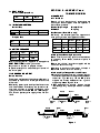
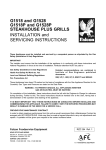
G2522 GRILL
INSTALLATION and
SERVICING INSTRUCTIONS
These appliances must be installed and serviced by a competent person as stipulated by the Gas Safety
(Installation & Use) Regulations.
IMPORTANT
The installer must ensure that the installation of the appliance is in conformity with these instructions and
National Regulations in force at the time of installation. Particular attention MUST be paid to -
Gas Safety (Installation & Use) Regulations
Health And Safety At Work etc. Act
Local and National Building Regulations
Fire Precautions Act
Detailed recommendations are contained in
Institute of Gas Engineers published
documents :
IGE/ UP/ 1, IGE/ UP/ 2
BS6173 and BS5440
These appliances have been CE-marked on the basis of compliance with the Gas Appliance Directive for the
Countries, Gas Types and Pressures as stated on the data plate.
WARNING - TO PREVENT SHOCKS, ALL APPLIANCES WHETHER
GAS OR ELECTRIC, MUST BE EARTHED
On completion of the installation, these instructions should be left with the Engineer-in-Charge for reference
during servicing. Further to this, The Users Instructions should be handed over to the User, having had a
demonstration of the operation and cleaning of the appliance.
IT IS MOST IMPORTANT THAT THESE INSTRUCTIONS BE CONSULTED BEFORE INSTALLING AND
COMMISSIONING THIS APPLIANCE. FAILURE TO COMPLY WITH THE SPECIFIED PROCEDURES MAY
RESULT IN DAMAGE OR THE NEED FOR A SERVICE CALL.
PREVENTATIVE MAINTENANCE CONTRACT
In order to obtain maximum performance from this unit we would recommend that a Maintenance Contract be
arranged with SERVICELINE. Visits may then be made at agreed intervals to carry out adjustments and
repairs. A quotation will be given upon request to the contact numbers below.
WEEE Directive Registration No. WEE/DC0059TT/PRO
At end of unit life, dispose of appliance and any replacement parts in a safe manner,
via a licenced waste handler.
Units are designed to be dismantled easily and recycling of all material is
encouraged whenever practicable.
Falcon Foodservice Equipment
HEAD OFFICE AND WORKS
Wallace View, Hillfoots Road, Stirling. FK9 5PY. Scotland.
SERVICELINE CONTACT PHONE - 01438 363 000
FAX - 01438 369 900
T100576 Ref. 3
Warranty Policy Shortlist
Warranty does not cover :Correcting faults caused by incorrect installation of a product.
Where an engineer cannot gain access to a site or a product.
Repeat commission visits.
Replacement of any parts where damage has been caused by misuse.
Engineer waiting time will be chargeable.
Routine maintenance and cleaning.
Gas conversions i.e. Natural to Propane gas.
Descaling of water products and cleaning of water sensors where softeners/conditioners are not fitted, or are
fitted and not maintained.
Blocked drains.
Independent steam generation systems.
Gas, water and electrical supply external to unit.
Light bulbs.
Re-installing vacuum in kettle jackets.
Replacement of grill burner ceramics when damage has been clearly caused by misuse.
Where an engineer finds no fault with a product that has been reported faulty.
Re-setting or adjustment of thermostats when unit is operating to specification.
Cleaning and unblocking of fryer filter systems due to customer misuse.
Lubrication and adjustment of door catches.
Cleaning and Maintenance
Cleaning of burner jets
Poor combustion caused by lack of cleaning
Lubrication of moving parts
Lubrication of gas cocks
Cleaning/adjustment of pilots
Correction of gas pressure to appliance.
Renewing of electric cable ends.
Replacement of fuses
Corrosion caused by use of chemical cleaners.
SECTION 1 - INSTALLATION
UNLESS OTHERWISE STATED, PARTS WHICH HAVE BEEN PROTECTED BY THE MANUFACTURER
ARE NOT TO BE ADJUSTED BY THE INSTALLER
1.1 MODEL NUMBERS, NETT WEIGHTS
and DIMENSIONS
MODEL
G2522
EQUIPMENT
WIDTH DEPTH HEIGHT WEIGHT GAS
(mm)
(mm)
(mm)
(kg) CONN.
900
585
505
74
Rp1/2
The grill may be mounted on any of the following
options -
Bench legs, floor stand or wall bracket.
1.2 SITING
There must be 150mm clearance all around the grill
from any combustible wall or object liable to damage
when overheated.
There must be a minimum vertical clearance of
900mm above the top edge of the flue to ensure no
overheating of overlying combustible surfaces.
A minimum clearance of 400mm from the sides
should be provided to allow removal of outer panels
for service access. Methods of mounting the unit are
available as detailed in Section 1.1. No grill should be
mounted directly upon a table.
Note
Upper sections of the unit are likely to become very
hot. It should therefore be positioned in a manner
which minimises the risk of accidental touching.
1.3 VENTILATION
The grill MUST be installed level in a well lit and
draught free position. Adequate ventilation, whether
natural or mechanical, must be provided to ensure
sufficient air for combustion and removal of
combustion products, which may be harmful to
health.
Recommendations for Ventilation of Catering
Appliances are given in BS5440:2.
Furthermore, to ensure sufficient room ventilation,
guidance on the volume of ventilation air required for
different types of catering equipment is provided in
the following table.
For multiple installations, requirements for individual
appliances should be added together.
Installation should be made in accordance with local
and/or national regulations applying at the time.
The flue discharges vertically from the top of the unit.
There must be no direct connection of the flue to a
mechanical extraction system or the outside air.
Ventilation Rate Required
m3/ min
ft3/min
Range, Unit Type
17
600
Pastry Oven
17
600
Fryer
26
900
Grill
17
600
Steak Grill
26
900
Boiling Pan
17
600
Steamer
17
600
Sterilizing Sink
14
500
Bains Marie
11
400
8.5 - 14
300 - 500
Tea/ Coffee Machine
Positioning the grill below a ventilated canopy is the
most suitable arrangement.
Warning
Remember, dirty extraction filters and drip trays
become combustible, hence the importance of
adhering to the specified flue clearance distance to
these items. Regular cleaning of extraction filters and
drip trays must be carried out.
1.4 GAS SUPPLY
The incoming service must be of sufficient size to
supply the full rate without excessive pressure drop.
A gas meter is connected to the service pipe by the
Gas Supplier.
An existing meter should be checked, preferably by
the Gas Supplier, to ensure that it is adequate to cope
with the rate of gas supply required. Installation pipes
should be fitted in accordance with IGE/UP/2.
The pipework size, from the meter to the unit, must
not be less than the appliance inlet connection, Rp1/2
(1/2" BSP).
An isolating cock must be located close to the
appliance (on the inlet side of the governor on Natural
Gas models) to allow shut down during an emergency
or routine service.
The installation MUST BE TESTED FOR GAS
SOUNDNESS, details of which can be found in
IGE/UP/1.
1.5 ELECTRICAL SUPPLY
Not applicable to this appliance.
1.6 WATER SUPPLY
Not applicable to this appliance.
SECTION 2 - ASSEMBLY and
COMMISSIONING
1.7 HEAT INPUTS Natural and Propane Gas
Model
G2522
kW
13.2
2.1 ASSEMBLY
2.1.1 Grill Unit
Btu/hr
45,000
Unpack grill and check that all components are
undamaged. Parts supplied loose are specified in
the contents list below
1.8 INJECTOR DIAMETERS Natural Gas
Model
G2522
Main Burners
X-lightingBurners
Pilot Burner
3 x Amal 380
2 x Amal 20
SIT No. 30
Main Burners
X-lightingBurners
Pilot Burner
3 x Amal 140
2 x Amal 10
SIT No. 19
Brander Drip Trough Brander Plate
Grid Shelf
Drip Tray
Gas Governor (Natural Gas only)
Additionally, the necessary plaques, supports and
cross-lighting burners are supplied as follows:-
Propane Gas
Model
G2522
1.9 SETTING PRESSURE
Gas Type
Natural
Propane
mbar
15
37
inches w.g.
6
14.8
Model
Plaques
CENTRE
SUPPORT
END
SUPPORT
X-LIGHTING
BURNER
G2502
4
-
4
-
G2512
8
3
4
1
G2522
12
6
4
2
G2532
6
4
4
-
2.1.2 Appliance Mounting Accessories
Details of various mounting options can be obtained
by contacting Falcon Sales, distributor or place of
purchase.
Refer to the individual instructions supplied with the
individual means of mounting.
Adherence to positioning clearances indicated in
Section 1.2 of this manual is mandatory.
A spring loaded governor, supplied with the appliance
MUST BE FITTED to natural gas models.
No governor is required on propane models.
A pressure test point is accessible upon removal of
the control panel.
2.1.3 Assembly of Support Bars and Plaques
1.10 BURNER ADJUSTMENT
Burner Aeration
a) When tunit has been installed in desired location,
the centre support bars can be positioned between
the burner lugs. Similarly LH and RH plaque
supports are located between burner lugs and
support angle. See Figure 1 below.
b) With support bars in position, plaques may be
inserted by placing these upon bars as illustrated
below.
The burners are fitted with fixed injectors. Aeration is
adjustable by means of a screw, positioned at the
burner inlet.
After setting pressure, the stability of the flame cones
should be checked. If necessary, the aeration screw
should be adjusted to achieve satisfactory cross
lighting of burners on both HIGH and LOW settings.
This will also prevent yellow tipping of the flame or
lift-off.
Plaque
Burner
Plaque
Support
angle
Plaque
RH Support
bar
LH Support
bar
Burner
Burner
Plaque
LH Support
bar
Support
angle
Plaque
Centre
support
Figure 1
2.2 CONNECTION TO THE GAS SUPPLY
Installation should be carried out in accordance with
the various regulations listed on the cover of this
document.
On NATURAL gas appliances, the adjustable
governor supplied, MUST be fitted to gas circuit and
securely fixed in a position that enables adjustment to
be carried out during commissioning.
PROPANE appliances do not require a governor.
Ensure that a gas Isolating cock is fitted to the supply
in convenient proximity to the grill.
2.3 CONNECTION TO AN ELECTRICAL SUPPLY
Not applicable to this appliance.
2.4 CONNECTION TO A WATER SUPPLY
Not applicable to this appliance.
2.5 COMMISSIONING
2.5.1 Testing and Purging
Pressure test installation for gas soundness and
purge any air from the supply.
2.5.2 Gas Pressure and Burner Flame Adjustment
a) Remove RH Side Panel.
b) Fit a pressure gauge to test point and light grill.
c) With burner at Full Flame position, setting pressure
should be as detailed in Section 1.9. On Natural
gas models, adjust governor as required.
d) With gas control in the Full Flame position, check
the flame cone is approximately 30mm in length.
If necessary, adjust by means of the aeration
screw in burner throat. Tighten locknut when
complete. (Refer to Section 1.10)
e) Check all burner parts cross light satisfactorily.
f) Turn control to Low Flame position and check that
flame cone reduces in length.
Note
LOW FLAME position is set at factory. Re-setting is
NOT necessary.
2.5.3 Soundness Checking and Re-assembly
Whilst grill is lit, test all integral gas carrying joints and
components for gas soundness. Use a suitable leak
detection fluid (i.e. Soap Solution).
TURN OFF gas control tap. REMOVE pressure
gauge and replace test point sealing screw.
ENSURE THAT A GAS TIGHT JOINT IS MADE.
Re-assemble all panels and components removed
during installation and commissioning. The drip tray,
wire grid and brander can then be placed in position.
2.6 INSTRUCTION TO USER
Hand over User manual. Ensure user understands
the procedures for lighting, cleaning and correct use
of appliance. Point out the location of the isolating
cock which may require to be shut down in event of
an emergency.
SECTION 3 - SERVICING and
CONVERSION
Important
Before carrying out any inspection, servicing or
exchange of components, turn OFF the gas at the
isolating cock and take steps to ensure that it is not
inadvertently turned on. Always remove the brander
and grid shelf.
After any maintenance task, check the appliance to
ensure that it performs correctly and carry out any
necessary adjustments as detailed in Section 1.
After carrying out any servicing or exchange of gas
carrying components -
ALWAYS CHECK FOR GAS SOUNDNESS!
3.1 GAS CONVERSION CHECK LIST
To convert from NATURAL to PROPANE gas -
Change injectors
Remove governor and adjust inlet pressure
accordingly
Adjust aeration
Change data plate
To convert from PROPANE to NATURAL gas -
Change injectors
Connect governor and adjust inlet pressure
accordingly
Adjust aeration
Change data plate
3.2 REMOVAL of PLAQUES and BURNERS
3.2.1 Plaques Only
a) Remove drip tray, grid shelf and brander.
b) Plaques may be replaced by reaching inside
compartment top and placing your fingers on
plaque face. Push plaque up carefully to dislodge
it from seating between bars and support angle.
c) Carefully replace plaque so that it is properly
seated on bar and support angle. The plaque
should be positioned hard against the burner.
3.2.2 Burners
a) Undo bottom fixings from LH outer side panel.
Remove bottom and side fixings from outer back
and lift clear.
b) Remove upper inner rear panel above burners by
undoing two fixings and lift it clear.
c) Reach inside top of compartment and remove
plaques and support bars.
d) The burner(s) without pilot bracket may now be
removed from injector seating.
e) To remove burner with pilot, refer to Section 3.2.2 ,
d) to e).
f) The burner is exposed and may be lifted from
injector seating.
3.3 REMOVAL OF INJECTOR
Following removal of burner, the injector may be
cleaned or replaced as desired. See Section 1.8 for
injector dimension details.
3.4 BURNER and INJECTOR CLEANING
Burners require to be cleaned periodically to ensure
that ports are free from blockage. This may be
facilitated by means of wire brushing. Individual ports
may be cleared with a suitable metal instrument.
Dislodged material should then be shaken out of
open burner end.
Should it become necessary to wash the burner(s),
ensure that they are completely dry and free from
cleaning materials before re-fitting to the appliance.
The injectors also require regular inspection and may
be cleaned with a wooden splinter or fuse wire.
Hard metal impliments MAY DAMAGE THE ORIFICE
and MUST NOT be used.
Upon re-fitting, check adjustment and flame picture
as described in Section 2.5.2.
3.5 FLAME FAILURE THERMOCOUPLE
a) Remove RH outer side panel.
b) Undo nut that secures thermocouple to SIT pilot
bracket using a 10mm spanner.
c) Undo nut that secures thermocouple to gas tap.
d) Withdraw faulty thermocouple and replace.
3.6 GAS VALVE
3.6.1 To Remove
Proceed as follows a) Pull off control knobs and remove front facia panel.
b) Undo nut that secures burner feed pipe to control.
c) Release pilot tubing nut from control and ease pilot
tube clear of location.
d) Remove fixings that secure control to gas pipe.
e)Manoeuvre control to enable removal of
thermocouple.
f) Withdraw control.
3.6.2 To Re-grease Control Tap
a) Remove fixings that retain front securing plate
while holding plate against internal spring
pressure.
b) Carefully withdraw plate, complete with operating
spindle.
c) Withdraw exposed rod, spring, brass washer, and
sealing washer, taking care not to lose any parts.
d) Withdraw plug and clean with a soft rag and also
clean mating surfaces in control body. Sparingly
re-grease plug with an approved heat-resistant
grease.
Re-assemble in reverse order taking care with the
central pin assembly. Fit spring to pin first, then brass
washer and finally sealing washer.
Ensure sealing washer fits snugly into recess at base
of plug. When re-fitting operating spindle, ensure
niting pin engages in plug slot.
3.7 GOVERNOR
3.7.1 General
The governor will normally require little servicing.
Before proceeding with any inspection or servicing,
TURN OFF THE GAS AT ISOLATING COCK.
3.7.2 Procedure
Check and if necessary, clear air breather hole of any
blockage. Ensure valve and seating are clean and
that diaphragm is in good condition.
ALWAYS RE-CHECK GAS PRESSURE at test point
after servicing governor.
SECTION 4 - SPARES
When ordering spare parts, ALWAYS quote
appliance TYPE and SERIAL No. This information
can be found on the data badge. A list of items
available, together with codes, is as follows Description
Plaque (single)
Thermocouple
Pilot burner body
Pilot orifice (Natural Gas)
Pilot orifice (Propane Gas)
Governor
Gas control
Knob for gas control
Disc for grid shelf handle
Handle for grid shelf
Grid shelf
Brander plate
Burner
Injector (Natural gas)
Injector (Propane gas)
X-lighting burner
X-lighting injector (Natural)
X-lighting injector (Propane)
Drip trough
Brick support - centre
Brick support - end
Part No.
531600010
531600030
531600050
531600070
531600075
535900001
537560020
535900000
531600410
531600420
531620130
531620110
531600230
531600220
531600225
531610150
531610140
531610145
531630140
531550130
531540120