1
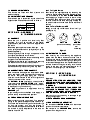
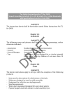
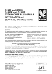
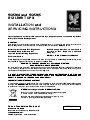
G350/4 and G350/5
BOILING TOPS
INSTALLATION and
SERVICING INSTRUCTIONS
These appliances must be installed and serviced by a competent person as stipulated by the Gas
Safety (Installation & Use) Regulations.
IMPORTANT
The installer must ensure that the installation of the appliance is in conformity with these instructions and
National Regulations in force at the time of installation. Particular attention MUST be paid to -
Gas Safety (Installation & Use) Regulations
Health And Safety At Work etc. Act
Local and National Building Regulations
Fire Precautions Act
Detailed recommendations are contained in
Institute of Gas Engineers published
documents :
IGE/ UP/ 1, IGE/ UP/ 2, BS6173 and BS5440
These Appliances have been CE-marked on the basis of compliance with the Gas Appliance Directive for the
Countries, Gas Types and Pressures as stated on the Data Plate.
WARNING - TO PREVENT SHOCKS, ALL APPLIANCES, WHETHER
GAS OR ELECTRIC, MUST BE EARTHED
On completion of the installation, these instructions should be left with the Engineer-in-Charge for reference
during servicing. Further to this, The Users Instructions should be handed over to the User, having had a
demonstration of the operation and cleaning of the Appliance.
IT IS MOST IMPORTANT THAT THESE INSTRUCTIONS BE CONSULTED BEFORE INSTALLING AND
COMMISSIONING THIS APPLIANCE. FAILURE TO COMPLY WITH THE SPECIFIED PROCEDURES MAY
RESULT IN DAMAGE OR THE NEED FOR A SERVICE CALL.
PREVENTATIVE MAINTENANCE CONTRACT
In order to obtain maximum performance from this unit we would recommend that a Maintenance Contract be
arranged with SERVICELINE. Visits may be made at agreed intervals to carry out adjustments and repairs.
A quotation will be given, upon request, to the contact numbers below
WEEE Directive Registration No. WEE/DC0059TT/PRO
At end of unit life, dispose of appliance and any replacement parts
in a safe manner, via a licenced waste handler.
Units are designed to be dismantled easily and recycling of all
material is encouraged whenever practicable.
Falcon Foodservice Equipment
HEAD OFFICE AND WORKS
Wallace View, Hillfoots Road, Stirling. FK9 5PY. Scotland.
SERVICELINE CONTACT PHONE - 01438 363 000
FAX - 01438 369 900
T100689 Ref. 1
SECTION 1 - INSTALLATION
UNLESS OTHERWISE STATED, PARTS WHICH HAVE BEEN PROTECTED BY THE MANUFACTURER
ARE NOT TO BE ADJUSTED BY THE INSTALLER
1.1 MODEL NUMBERS, NETT WEIGHTS
and DIMENSIONS
MODEL
WIDTH DEPTH
mm
mm
G350/4
350
650
G350/5
700
650
1.2 SITING
Recommendations for Ventilation of Catering Appliances are given in BS5440 : 2. Furthermore, to
ensure sufficient room ventilation, guidance on the
HEIGHT WEIGHT WEIGHT volume of ventilation air required for different types of
mm
kg
lbs
catering equipment is provided in the table below. For
multiple installations the requirements for individual
305 25.5 56
appliances should be added together. Installation
305
46
101 should be made in accordance with local and/ or
national regulations applying at the time. A competent
installer MUST be employed.
These boiling tops can be installed on a table or
counter top, or alternatively on the purpose made
metal stand supplied by Falcon.
The boiling top units can be installed to within 25mm
of a combustible wall at the back and sides, and a
clear space of 1000mm should be allowed between
the top of the flue outlet and overlying combustible
surface.
Important
If the appliance is to be installed in suite formation
with other matching appliances of the Falcon 350
series, the instructions for all units must be consulted
to determine the necessary clearances to any
combustible rear wall or overlying surface. Some
appliances require greater clearance than others, and
the largest figure quoted in the individual instructions
will determine the clearance for the clearance for the
complete suite of adjoining appliances.
1.3 VENTILATION
EQUIPMENT
Ventilation Rate Required
ft3/min
m3/ min
Range, Unit Type
17
600
Pastry Oven
17
600
Fryer
26
900
Grill
17
600
Steak Grill
26
900
Boiling Pan
17
600
Steamer
17
600
Sterilizing Sink
14
500
Bains Marie
11
400
8.5 - 14
300 - 500
Tea/ Coffee Machine
Adequate ventilation, whether natural or mechanical,
must be provided to supply sufficient fresh air for
combustion and allow easy removal of combustion
products which may be harmful to health.
1.4 GAS SUPPLY
The incoming services must be of sufficient size to
supply full rate without excessive pressure drop. A
gas meter is connected to the service pipe by the Gas
Supplier. An existing meter should be checked,
preferably by the Gas Supplier to ensure that the
meter is adequate to deal with the rate of gas supply
required.
Installation pipework should be fitted in accordance
with IGE/UP/2. The size of the pipes from the meter
to the appliance must be not less than that of the
appliance inlet connection, Rc1/2 (1/2" BSP female).
An isolating cock must be located close to the
appliance to facilitate shutdown during an
emergency or routine servicing. the cock must be
easily accessible to the user.
1.5 TOTAL RATED HEAT INPUTS NATURAL and PROPANE GAS
Model
G350/4
G350/5
kW
9.5
19
Btu/hr
32,400
64,800
1.6 INJECTOR SIZE NATURAL and PROPANE GAS
Model
G350/4
G350/5
Natural
ù 1.8mm
ù 1.8mm
Propane
ù 1.1mm
ù 1.1mm
1.7 GAS PRESSURE
The following operating pressures apply to both
models.
mbar
inches w.g
Natural
15
6
Propane
37
14.8
The pressure test point is sited on the gas manifold
behind the front facia panel.
An adjustable governor (Rc1/2) is provided for use on
NATURAL GAS SUPPLIES ONLY.
1.8 BURNER ADJUSTMENTS
The burners are fitted with fixed injectors and
aeration settings.
NO ADJUSTMENT IS NECESSARY
The reduced rate is determined by the size of the
bypass screw. These dimensions are as follows NATURAL
PROPANE
ù mm
0.95
0.6
SECTION 2 - ASSEMBLY
& COMMISSIONING
2.3.1 To Light A Burner
First identify the appropriate tap by observing the
marker on the facia panel. Push the tap inwards, then
turn anti-clockwise to the FULL FLAME POSITION
whilst applying a lit taper or match to the rim of the
burner-head. Hold the control knob in for up to 20
seconds in order for the flame to engage. The tap can
be turned further anti-clockwise to reduce the flame if
desired.
2.3.2 To Turn The Burner OFF
Simply turn the tap clockwise as far as it will go.
(see Figure 1)
2.1 ASSEMBLY
Place the unit in position and level using feet
adjusters. If it is to be mounted on the special
purpose stand, refer to the instructions supplied with
the stand.
Check the open-top burner assemblies: pan supports, spillage deflectors and spillage trays may be
packed separately.
The spillage tray slides through an aperture in the
front panel, beneath the control knobs.
The side spillage deflectors have a raised edge which
engages under the fixed side trims.
The lower burner bodies and injectors of the open top
are fixed and should not require adjustment.
The upper burner bodies and heads fit loosely on to
their bases which protrude through the drip shed.
2.2 CONNECTING TO THE GAS SUPPLY
Both models are furnished with a compression elbow
fitting, terminating in a Rc1/2 thread for connecting to
the mains. The gas supply piping, etc. must be
installed in accordance with the various regulations
listed on the cover of this manual.
On NATURAL GAS installations, the adjustable
governor provided MUST BE FITTED in the supply,
securely fixed in a position which enables adjustment
to be made during commissioning.
DO NOT fit governors to appliances burning
PROPANE gas.
A gas isolating cock must be fitted in the supply, in a
position readily accessible to the operator.
2.3 PRE-COMMISSIONING CHECK
After connecting to the gas supply, fit a pressure
gauge to the pressure test-point (see section 1.7),
and check the installation for gas-soundness. Purge
air from the system, and light the burners in
accordance with the procedures detailed below. With
the burners lit, adjust the pressure to the value as
detailed in section 1.7.
OFF
FULL ON
(turn anti-clockwise)
Figure 1
SIMMER
(turn further
anticlockwise)
2.4 INSTRUCTION TO USER
After installing and commissioning the appliance,
please hand the User's Instructions to the user or
purchaser and ensure that the person(s) responsible
understands the instructions for lighting, cleaning and
correct use of the appliance. It is important the ensure
that the location of the gas isolating cock is made
known to the user, and that the procedure for its
operation in an emergency is demonstrated.
SECTION 3 - SERVICING
& CONVERSION
Important
BEFORE ATTEMPTING ANY SERVICING, TURN
OFF THE ISOLATING COCK AND TAKE STEPS TO
ENSURE THAT IT CAN NOT BE INADVERTENTLY
TURNED ON.
AFTER ANY MAINTENANCE TASK, CHECK THE
APPLIANCE TO ENSURE THAT IT PERFORMS
CORRECTLY AND CARRY OUT ANY NECESSARY
ADJUSTMENTS AS DETAILED IN SECTION 1.
After carrying out any servicing or exchange of gas
carrying components -
ALWAYS CHECK FOR GAS SOUNDNESS!
3.1 GAS CONVERSION CHECK LIST
For conversion to NATURAL GAS, add the correct
governor and set burner pressure.
For conversion to PROPANE GAS, remove the
governor from the gas circuit.
Other considerations :
CHANGE INJECTORS
CHANGE BY-PASS SCREW AND SET LOW RATE
CHANGE DATA PLATE
Also, apply grease to the operating spindle where it
enters the plug.
3.2 REMOVAL OF CONTROL PANEL
To Remove
Pull off all control knobs.
Remove the screws holding the panel to the
appliance body.
Ease the panel down and pull forwards.
3.3 BURNERS
Remove the pan supports from the hob.
Remove the burner head and top body, together with
the drip shed.
To remove the lower body of the burner from the
respective pipework, undo the injector holder grub
screw in the top of the relevant burner neck.
Undo the nuts which secure each burner lower body
to the support.
Remove the support by lifting it clear of the burner
bodies. Remove the burner body by pulling it away
from the injector holder.
Replace in reverse order.
3.4 INJECTORS
Remove the pan support and drip shed as detailed in
Section 3.3.
Undo the injector from the respective holder using a
14mm ring spanner. Ensure that the injector remains
in a steady position.
Replace in reverse order.
3.5 FLAME FAILURE
THERMOCOUPLE/ELECTRODE
Remove the pan support and drip shed as detailed in
Section 3.3.
Undo the thermocouple connection at the FFD
section of the gas tap.
Undo the top nut which secures the thermocouple to
the burner support. Pull the thermocouple through the
support underside.
Replace in reverse order.
3.6 GAS TAPS
Remove the control panel as detailed in Section 3.2.
To Service
Remove the two screws from the front of the tap body
and withdraw the spindle and niting arrangement thus
allowing the plug to be eased out.
Replace in reverse order.
Clean all parts with a soft rag, and sparingly
re-grease the plug with an approved high
temperature grease.
Note
Tap plugs and bodies are made in MATCHED pairs,
DO NOT INTERCHANGE.
Undo the compression fitting nut on the gas supply
pipe at the gas tap rear.
Remove the thermocouple connection from the FFD
section of the tap.
Undo two screws and gently remove the tap from the
supply manifold.
Before refitting the tap to the float rail, check the
serviceability of the rubber sealing washer. If in doubt,
fit a new washer.
Replace in reverse order and check for gas
soundness.
3.7 GOVERNOR
This applies to NATURAL GAS UNITS ONLY.
The type of governor used will normally require little
servicing. The air breather hole should be checked for
dirt blockage.
Always re-check the pressure at the test point after
governor maintenance.
SECTION 4 - SPARES
When ordering spare parts, always quote the unit
type and serial number. This information can be
found on the data plate located to the oven base
plate. On boiling table models, the data plate is
located on a swing plate at the rear RH side. A list of
available parts can be found in the accompanying
spares section of this document pack.