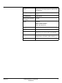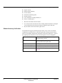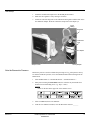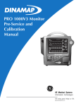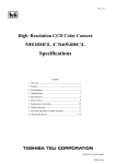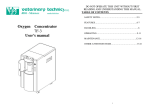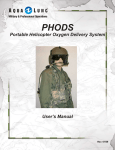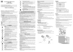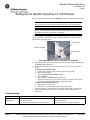
1
Operator Setup Instructions PN 2000966-232 English Setting Up the Dash® CapnoFlex LF CO2 Module These instructions pertain to Dash 3000/4000 software versions 4 and previous. :$51,1* Route all tubing away from the patient’s throat to avoid strangulation. &$87,21 Do not use this module on patients that cannot tolerate the removal of 50 ml/min from their total minute ventilation. The CO2 chapter of the Dash patient monitor operator manual has additional safety information and details on the CO2 menu options. Keep these setup instructions with the manual. CO2 connector Cannula connector Scavenger port 1. 2. 3. Dash Patient Monitor and Dash CapnoFlex LF CO2 Module Plug the module into the CO2 connector on the patient monitor. The message WARMING UP is displayed. Follow the steps below based on the message you see after the module is warm. CAL SENSOR TO ZERO CELL a. Connect the cannula to the module but not to the patient. b. Enter the CO2 menu. c. Select CAL SENSOR TO ZERO CELL. d. Select READY. The message CALIBRATING is displayed. e. Wait for the message to clear then connect the cannula to the patient. (Refer to the instructions that come with the cannula.) CHECK ADAPTER ADAPTER CAL a. The module is ready to use. b. Connect the cannula to the module and to the patient. Patient monitoring of CO2 begins. Refer to the CO2 chapter of the Dash patient monitor operator’s manual for details about monitoring this parameter. Troubleshooting Message CHECK ADAPTER ADAPTER CAL Problem n The cannula is not connected. n The cannula is blocked. n The module was calibrated without the cannula connected. Solution n Connect the cannula to the module. n Replace the cannula. n Connect the cannula to the module and calibrate. Refer to the module’s service manual for additional troubleshooting information. Revision C GE Medical Systems Information Technologies • 8200 W. Tower Ave., Milwaukee, WI 53223 U.S.A. © 2003 GE Medical Systems Information Technologies. All rights reserved. 18 April 2003 DASH CapnoFlex LF CO2 Module Service Instructions Software Version A 2000966-233 Revision A NOTE: Due to continuing product innovation, specifications in this manual are subject to change without notice. DASH is a trademark of GE Medical Systems Information Technologies registered in the United States Patent and Trademark Office. All other trademarks contained herein are the property of their respective owners. © GE Medical Systems Information Technologies, 2003. All rights reserved. T-2 DASH CapnoFlex LF CO2 Module 2000966-233 Revision A 28 February 2003 Description The DASH CapnoFlex LF CO2 module, hereafter referred to as the module, connects to the CO2 connector of the DASH patient monitor and provides CO2 monitoring for intubated and non-intubated patients. The module operates at a low flow rate to allow monitoring of adult and neonatal patients. There are no controls or indicators on the module. The module is compatible with all available versions of DASH software that have the CO2 function enabled. NOTE Please refer to the appropriate DASH patient monitor service manual for more detailed information. DASH CapnoFlex LF CO2 Module The module is attached to a retainer clip that is affixed to the DASH with double-sided adhesive. Instructions for affixing the retainer clip are shipped with the module. Revision A DASH CapnoFlex LF CO2 Module 2000966-233 3 Technical Specifications 4 Manufacturer Respironics Novametrix, Inc. Displayed Information Inspired and expired CO2 concentration Respiration rate (BPM) CO2 capnograph Measurement Method Diverting (LoFlo) infrared absorption (dual wavelength ratiometric) CO2 Measurement Units: Millimeters of mercury (mmHg) Range: 0 to 100 mmHg Accuracy: 0 – 40 mmHg - ±2 mmHg 41 – 70 mmHg - ±5% of actual 71 – 100 mmHg - ±8% of actual All specifications ±12% of actual from 80 to 150 BrPM Rise Time: <200 milliseconds System Response Time: <3 seconds Interference Device accuracy not affected due to the effects of interference by N2O, O2, water vapor, and concentrations of no more than 5% of halogenated anesthetic agents. Measurement Resolution 1 mmHg CO2 Averaging CO2 averaging is user selectable from the following times: Single breath 10 seconds 20 seconds N2O Compensation Configure for N2O from 0% to 40% or N2O > 40%. O2 Compensation Configured for O2 from 0% to 60% or O2 > 60%. Barometric Pressure Compensation The system automatically compensates for changes in barometric pressure over the atmospheric pressure range of 530 – 785 mmHg. Warm-up Time From connection of the module at room temperature it is 80 seconds maximum to initial CO2 indication, and 3 minutes to full operating specifications. Patient Status Alarms Upper and lower limits for inspired and expired CO2 user selectable at the host. Respiration rate (BrPM) Measurement units: Breaths per minute (BrPM) Range: 0 to 150 BrPM Accuracy: ±1 BrPM Resolution: 1 BrPM Averaging: Respiration rate averaging is user selectable from the following times: Single breath 10 seconds 20 seconds DASH CapnoFlex LF CO2 Module 2000966-233 Revision A Revision A Diverting (LoFlo) Sampling System Flow rate: 50 ml/min ± 10 ml/min Response time: 5% CO2 step response 10 to 90% less than 200 milliseconds Sample System Integrity Acceptable leak rate is 2.4 in H2O/min. at 3 psi test pressure. Power Requirements Powered by host Maximum power consumption (non-isolated) 2.5 Watts Physical Dimensions Weight: 6 ounces (<1 kilogram) Width: 4.0 inches (102 mm) Depth: 2.58 inches (65 mm) Cooling Method Natural convection Heat Dissipation Less than 2.5 watts Temperature Operating: 0° to 40° C (32° to 104° F) non-condensing Storage: -40° to 70° C (-40° to 158° F) non-condensing Pressure and Altitude Operating: -273.1 to 2,942.8 meters (-896 to 9,655 ft.) Storage: -609.6 to 4,572 meters (-2,000 to 15,000 ft.) Audible Noise <45 db DASH CapnoFlex LF CO2 Module 2000966-233 5 Theory of Operation The module is designed to work specifically with the DASH 3000/4000 monitor. It is an infra red CO2 analyzer utilizing on the mainstream Capnostat technology. It contains a sampling pump for pulling a gas sample into the analyzer. It mounts to the side of the DASH and connects to the existing CO2 connector. The supporting electronics and software in the DASH common to both the main stream sensor and the DASH CapnoFlex LF module. The sampling flow rate is fixed and internally regulated to 50 ± ml/min. A differential sensor pressure in the sampling circuit provides the signal for regulation. An occlusion can be detected by way of another pressure sensor constantly monitoring the pressure the sampling system for increased pressure. If the preset pressure is exceeded for 15 seconds the pump is turned off. The inlet to the analyzer is mechanically unique and only accepts an approved sampling line containing the water protection trap. The sampling cell and water trap is integral to the disposable sampling assembly. A reflective optical sensor provides a signal for enabling the pump. The analyzer has all calibration factors stored in an EEPROM. This allows for the use of the analyzer with any DASH as the calibration factors are read into the DASH each time a module is connected. Below is a block diagram of the module. DASH CapnoFlex LF CO2 Module EEPROM Data Optics Source Drive Data/Ref Signals Active Electronics Power Control Pneumatics flow control and alarms (Pump, Pressure Transducers, Tubing) Host Monitor Data/Ref Signals (Source, Detector) Thermal System Temp (Heater, Sensor) 6 DASH CapnoFlex LF CO2 Module 2000966-233 Revision A Maintenance and Checkout Manufacturer Recommendations The manufacturer recommends the following: Visual Inspection — performed by service personnel upon receipt of the equipment, every 12 months thereafter. Cleaning — performed by service personnel upon receipt of the equipment, every 12 months thereafter. Checkout Procedure — performed by qualified service personnel every 12 months. Manufacturer Responsibility WARNING Failure on the part of all responsible individuals, hospitals or institutions, employing the use of this device, to implement the recommended maintenance schedule may cause equipment failure and possible health hazards. The manufacturer does not, in any manner, assume the responsibility for performing the recommended maintenance schedule, unless an Equipment Maintenance Agreement exists. The sole responsibility rests with the individuals, hospitals, or institutions utilizing the device. Visual Inspection Inspect the module prior to installation and once every 12 months thereafter. Carefully inspect the equipment for physical damage to the case. Refer damaged equipment to qualified service personnel. Inspect all external connections for loose connectors. Refer damaged connectors to qualified service personnel. Cleaning Use one of the following approved solutions: Revision A cidex solution, or sodium hypochlorite bleach (diluted), or mild soap (diluted) lint-free cloth dust remover (compressed air) DASH CapnoFlex LF CO2 Module 2000966-233 7 To avoid damage to the equipment surfaces, never use the following cleaning agents: organic solvents, ammonia based solutions, acetone solution, alcohol based cleaning agents, betadine solution, a wax containing a cleaning substance, or abrasive cleaning agents. 1. Disconnect the module from the DASH. 2. Use a clean, lint-free cloth and one of the cleaning solutions listed above. Wring the excess solution from the cloth. Do not drip any liquid into open connectors. 3. Dry the surfaces with a clean cloth or paper towel. Module Accuracy Verification The manufacturer suggests performing this procedure yearly. Use the CO2 Module Calibration Kit, pn 405910-001 (or equivalent gas fixture with specifications shown below) to successfully complete this verification. See the How to Reach Us… pages at the beginning of this document to order the kit through Accessories and Supplies. 8 Calibration Gas Mixture 10% carbon dioxide, 25% oxygen, balance nitrogen Minimum accuracy: ±0.05% Regulator Approximately 1.5 liters per minute Must have CGA value of cylinder outlet Tubing Type: Tygon Endotracheal Tube (ET) Adapter Size dependent on airway adapter and tubing size Airway Adapter Use CapnoFlex LF Airway Adapter (see “Parts List” on page 12) DASH CapnoFlex LF CO2 Module 2000966-233 Revision A Test Setup 1. Attach the module with sample line to the DASH patient monitor. 2. Make sure the regulator is off by turning it clockwise. 3. Attach one end of the large tube to the calibration tank regulator and the other end to the calibration adapter. Do NOT connect the sample line to the adapter yet. Tygon Tubing Regulator Calibration tank ET Adapter Sample Line Airway Adapter Note the Barometric Pressure Barometric pressure is used to calculate the percentage of CO2 in the patient’s airway. To read the barometric pressure, access the SERVICE MODE menu starting from the MAIN menu. 1. Select MORE MENUS -> MONITOR SETUP -> SERVICE MODE -> 2. Enter password using the Trim Knob control to select the day and month from monitor screen with leading zeros. (e.g. July 4 = 0407) NOTE Check for the date in the upper left of the monitor screen. 030B Revision A 3. Select CALIBRATE, then CO2 SERVICE. 4. From the CO2 SERVICE window, note the Barometric Pressure._______ DASH CapnoFlex LF CO2 Module 2000966-233 9 Verify Accuracy 1. Return to MORE MENUS and select CO2 to open the menu. 2. Select UNITS: and set to MMHg. 3. Select CAL SENSOR TO ZERO CELL, then select READY. The on-screen message reads CALIBRATING. 4. When the CALIBRATING message disappears, connect the sample line to the calibration adapter. 5. Turn on the tank regulator for several seconds, then turn it off. If the NO BREATH DETECTED message appears, simulate breathing by turning the regulator on for several seconds, then off for several seconds. 6. Read the EXP number. _________ EXP mmHg = CO2 value on tank X Barometric Pressure as noted above. Tolerance = ± 8% If the module tolerance is outside the above range, return the module for repair. 10 DASH CapnoFlex LF CO2 Module 2000966-233 Revision A Troubleshooting The following table lists screen messages and other indications that there is a problem with the module. See “Parts List” on page 12 for item numbers and descriptions. Message CHECK ADAPTER ADAPTER CAL Possible Cause/Solution A failure in the CO2 module board or a failure in the flow circuit. Check the flow circuit first. 1. Insert sample line. 2. Perform zero cell calibration. 3. Swap sample line with known good sample line. 4. Replace sample line. 5. Swap module with known good module. 6. Return module for repair. WARMING UP Allow device to warm-up for 1 minute. Check if sample line is properly installed. 1. Replace sample line. 2. Return module for repair. CAL SENSOR TO ZERO CELL Perform zero cell calibration. Check if sample line is properly installed. 1. Replace sample line. 2. Return module for repair. CAL ERROR SENSOR 1. Replace sample line. 2. Return module for repair. SERVICE CO2 SENSOR Return module for repair. SERVICE CO2 TEMP Return module for repair. CANNOT CALIBRATE Module thinks it has detected a breath. Wait 2 minutes. 1. Perform zero cell calibration. 2. Return module for repair. Other Revision A Possible Cause/Solution No CO2 parameter box 1. Check if module is attached. 2. Check if module is fully connected. 3. Swap module with known good module. 4. Return module for repair. Incorrect CO2 Readings 1. Check if sample line is properly installed. 2. Replace sample line. 3. Return module for repair. No Power Check if DASH is on. Plug into AC power. DASH CapnoFlex LF CO2 Module 2000966-233 11 Parts List See the How to Reach Us… page at the front of this document to order service parts. The table below lists the part item number and description. Item Number Item Description 2015023-001 DASH CAPNOFLEX LF CO2 MODULE 2013676-001 MOUNTING BKT DASH CAPNOFLEX LF CO2 MODULE 405910-001 KIT CO2 MODULE CALIBRATION 9504-016 GAS SCAVENGER 10FT TGB W/CPLG 2013066-001 CAPNOFLEX CO2 NASAL CANNULA - ADU 2013066-002 CAPNOFLEX CO2 NASAL CANNUAL - PED 2013066-003 CAPNOFLEX CO2 NASAL CANNULA - INF 2013066-004 CAPNOFLEX CO2 NASAL CANN W/ O2 - ADU 2013066-005 CAPNOFLEX CO2 NASAL CANN W/ O2 - PED 2013067-001 CAPNOFLEX CO2 ORAL/NASAL CANNULA - ADU 2013067-002 CAPNOFLEX CO2 ORAL/NASAL CANNULA - PED 2013067-003 CAPNOFLEX CO2 ORAL/NASAL CANN W/O2 - ADU 2013067-004 CAPNOFLEX CO2 ORAL/NASAL CANN W/O2 - PED 2013068-001 CAPNOFLEX LF AIRWAY ADAPTER - ADU/PED 2013068-003 CAPNOFLEX LF AIR ADPTR W/NAFION -ADU/PED 2013069-001 CAPNOFLEX LF SAMPLE LINE W/MALE LUER 2013069-002 CAPNOFLEX SMPL LN W/ MALE LUER & NAFION Revision History Each page of the document has the document part number and revision letter at the bottom of the page. The revision letter changes each time the document is updated. Revision A 12 Date 28 February 2003 DASH CapnoFlex LF CO2 Module 2000966-233 Comment Initial release. Revision A 0459 gemedical.com World Headquarters GE Medical Systems Information Technologies, Inc. 8200 West Tower Avenue Milwaukee, WI 53223 USA Tel: +414.355.5000 800.558.5120 (US only) Fax: +414.355.3790 European Representative GE Medical Systems Information Technologies GmbH Postfach 60 02 65 D-79032 Freiburg Germany Tel: +49 761 45 43 - 0 Fax: +49 761 45 43 - 233 Asia Region GE Medical Systems Asia 7-127, Asahigaoka 4-chome Hino-shi, Tokyo 191-8503 Japan Tel: +81-42-582-6824 Fax: +81-42-582-6830