1
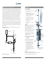
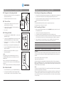
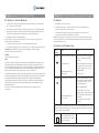
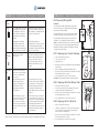
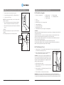
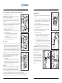
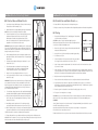
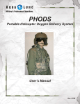
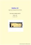
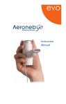
2000i
Operating Instruction Manual
Contents
Page
Section 1
Indications and Contraindications
3
Section 2
Definitions, Warnings and Cautions
3
Section 3
About Vapotherm 2000i Product Description
5
Section 4
4.1
4.2
4.3
4:4
4:5
4:6
General 2000i Set up and instructions
Set Up – The 2000i Unit
Set Up – Selecting the Vapor Transfer Cartridge
Set Up – Inserting the Vapor Transfer Cartridge
Set Up – Inserting the Patient Delivery Tube
Set Up – Vapotherm Spike Set (VSS-1)
Set Up – Connect to a Gas Source
7
7
8
8
9
9
Section 5
5:1
5:2
5:3
5:4
5:5
5:6
5.7
Operations
Operations – Prepare for Activating the Unit
Operations – Turn on Flow
Operations – Priming the Unit
Operations – Activate the Unit
Operations – Setting the Temperature and Warm-Up
Operations – Connecting to a Patient
Operations – General Guidelines
Section 6
6.1
6.2
6.3
6.3.1
6.3.2
6.3.3
Alarms and Troubleshooting
General
Alarm and Troubleshooting Table
Component Change-outs
Replacing the Vapor Transfer Cartridge
Replacing the Patient Delivery Tube
Replacing the VSS-1 Spike Set
Section 7
Removing From Patient and System Shut Down
Section 8
8.1
8.2
8.3
8.4
8.5
8.6
Routine Disinfection Procedure
Disinfection Supplies
Pre-cleaning Process
Pre-disinfection Cleaning and Decontamination
Set-up
Disinfect Gas and Water Circuits
Drying
Section 9
9.2
Specifications
Definitions and symbols
22
22
Section 10
Warranty Information
23
Section 11
Reference and Bibliography
24
™
Appendix A – Disinfection Solution
Appendix B – Sample Disinfection Log
Operating Instruction Manual
Section 1 Indications and Contraindications
Primary Indications:
Used to warm and humidify breathing gases, generally prescribed during oxygen therapy where concentrations
of oxygen greater than ambient air are utilized to treat symptoms and manifestations of hypoxia including:
• Documented hypoxemia: decreased Pa0 in blood below normal range
2
10
10
10
10
11
11
12
• Acute care in which hypoxemia is suspected
• Severe trauma
• Acute myocardial infarction
Secondary Indications:
• Managing hypothermia
• Treating bronchospasm caused by cold air
Contraindications:
General:
• Any situations in which humidification is contra-indicated (see AARC Clinical Practice Guidelines)
Specific to Nasal Cannula:
• Patients with occluded or defective nares should not use the system.
Section 2 Definitions, Warnings and Cautions
2.1 Definitions
13
13–14
15
15
15
15
16
17
17
18
18–19
20
21
25–26
27
Page 2
A WARNING indicates that a potentially harmful situation may occur.
A CAUTION indicates a condition that may lead to equipment damage, malfunction, or
inaccurate operation.
A NOTE indicates a point of emphasis to make operation more efficient or convenient.
Aseptic Technique is practices and procedures performed under carefully controlled conditions with
the goal of minimizing contamination by pathogens. Specifically with respiratory equipment, especially
with reference to the Vapotherm 2000i, this includes proper hand washing and avoiding direct hand
contact with connection points.
Please take the time to familiarize yourself with the definitions, warnings, cautions and notes listed in this
manual. They cover safety considerations, special requirements, and regulations.
The user of this product assumes sole responsibility for any malfunction due to operation or maintenance
performed by anyone not trained by Vapotherm™ staff or official training documentation.
When handling any part of the Vapotherm 2000i, always follow hospital infection control guidelines and
Standard Precautions. Vapotherm recommends that users follow the disinfection procedure found in this
manual. Vapotherm also recommends that users follow the Centers for Disease Control (CDC) publications:
Guidelines for Maintenance of In-Use Respiratory Therapy Equipment and Guidelines for Prevention of
Nosocomial Pneumonia.
®
2.2 General Warnings
• Federal Law (U.S.) restricts the sale of this device to, or by the order of any physician.
• This is a humidification device generally used for providing continuous flows of breathing gas.
The Vapotherm 2000i is not a ventilatory device and should not be used as life support.
®
• This device will not operate without flow.
Operating Instruction Manual
Page 3
Section 2 Warnings and Cautions
Section 2 Warnings and Cautions
General Warnings (cont.)
2.4 General Inspection
• The Vapotherm 2000i must be disinfected between each patient use and after 30 days of use on the
same patient.
• Gas flow delivered by this device is limited to 40 liters per minute. Maximum operational flow rate
should not be exceeded.
• Prior to use machine should be positioned and secured to a sturdy IV pole.
• The system includes several disposable elements that are labeled as single patient use only: do not
attempt to sterilize or reuse. Follow all local and federal regulations for disposal.
• Oxygen supports combustion; this device should not be used near or around open flames, oil, grease
or any flammables or anesthetics.
• Performance verification must be performed prior to use.
• Service on the device should be performed by qualified, certified service technicians ONLY.
• To prevent injury do not attempt to perform any service to the Vapotherm 2000i while a patient is
connected to the device.
• If the device is damaged or not working properly do not use. Contact Vapotherm or your authorized
Vapotherm representative.
• Do not operate if power cord is damaged.
• The device should not be turned on and left unattended.
• Do not use the Vapotherm 2000i in or around water other than the water bag that feeds the system.
• Failure to utilize sterile water supply or clean gas supply may increase risk of bacterial contamination.
• The Vapotherm 2000i utilizes warmed water and can pose a risk for colonization of bacteria and
patient infection if disinfection procedures are not followed.
• Gas flow is external to the Vapotherm, but the care giver should confirm the integrity of all respiratory
gases utilized to ensure they are free of contamination.
• Gas supply must be made of clean dry medical grade gas to prevent harm to the patient and prevent
damage to the Vapotherm 2000i.
• An oxygen analyzer with alarms must be used when the delivered concentration level is critical. The
Vapotherm 2000i does not provide oxygen concentration analysis capability.
• To reduce any potential transmission of contaminated water from the system, all assembly and/or
disassembly of the unit should take place outside the primary care areas.
When unpacking the Vapotherm 2000i system , ensure that the unit is inspected for damage before use.
Report any damage or missing parts immediately to your authorized Vapotherm distributor.
®
When renting a Vapotherm 2000i, customers should require the rental service to provide a certification
that the machine has been disinfected before accepting delivery.
Section 3 About the Vapotherm 2000i and 2000h
The Vapotherm™ 2000h for home use consists of the combination of a 2000i unit and the “Home Care
Compressor Kit (Part number HCK200-M)”. The HCK-200 Kit consists of an HS-100 Stand, a 5060A
Room Air Compressor and Flowmeter assembly.
1. A Vapotherm authorized Durable Medical Equipment (DME) Supplier is responsible for the following:
•
•
•
•
•
Assembling the 2000i unit and the kit components
Instructing the user in their responsibilities for operating the system
Providing 1000 ml sterile water bags as needed
Routine servicing of the system
R
emoving, replacing, and disposing of the disposable components (Vapor Transfer Cartridge,
Vapotherm Spike Set -1 & Delivery Tube) every 30 days
• D
isinfecting of the 2000i unit every thirty days following the procedure found in
Section 8.1 – 8.6 of the 2000i Operating Instruction Manual
2. The user/home care provider is responsible for the following:
•
•
•
•
Change nasal cannulas when soiled or excessively wet from secretions. Dispose of properly.
Installing and replacing the sterile water bag
Avoid liquid spills on the components
Do not attempt any repairs. If you have any problems with your Vapotherm 2000i device
notify the DME provider immediately
• The 2000i is not a Continuous Positive Airway Device (CPAP). There are no controls to deliver or
monitor airway pressure. The 2000i humidifies breathing gases that are delivered externally through
standard air/oxygen blender and flowmeter. The 2000i should not be used to deliver pressure in a
closed system.
2.3 Cautions
• Verify that the power source is compatible with the electrical specifications shown on each component.
For proper grounding reliability, connect the 2000i power cord only to a properly marked hospital grade
receptacle. DO NOT USE EXTENSION CORDS. If any doubt exists as to the grounding connection, DO NOT
operate the device.
• Do not immerse the Vapotherm 2000i in water. Do not steam or gas sterilize the Vapotherm 2000i.
• Read and understand this manual prior to operating the system.
• The Vapotherm 2000i must be disinfected if the water circuit is opened up by removing or replacing a
component.
• Aseptic techniques (including proper hand washing and avoiding direct hand contact with connection
points) and Standard Precautions should always be followed when handling medical equipment.
• Standard Precautions should always be followed when coming in contact with patients.
Operating Instruction Manual
Page 4
Operating Instruction Manual
Page 5
Section 4 Set-up
Section 3 About the Vapotherm 2000i
®
The Vapotherm 2000i warms and humidifies flows of air, oxygen or medical gas blends for delivery to a
patient, by nasal cannula or Vapotherm approved interface.Warming and humidification of breathing gas
occurs in a Vapor Transfer Cartridge, where air and water are separated by a membrane permeable to
water vapor. The membrane consists of microtubules constructed of polysulfone material. The membrane
meets HIMA (Health Industry Manufacturers Association) standards on filters for sterilizing liquids and has
been shown to effectively exclude bacteria from crossing from the water circulation to the gas flow.
The warmed humidified gas stream reaches the patient via a patented triple lumen Patient Delivery Tube.
Humidified gas flow is delivered through the center lumen. The outer lumens contain water which is
warmed via an internal heater and propelled through the system via an internal pump (See schematic,
fig. 1). This maintains breathing gas temperature and minimizes condensation. The final patient interface
is a Vapotherm nasal cannula or approved interface configured to minimize resistance and heat loss.
NOTE: The water circuit and gas circuit of the Vapotherm 2000i do not come in contact with each other.
Respiratory gases are supplied to the Vapotherm™ 2000i from an external gas supply, typically through a
standard wall-mounted flow meter connected to the hospital medical gas supply. Gas flow rate is controlled
by the external flow meter or medical gas blender. There are no flow controls on the Vapotherm™ 2000i.
Connections for gas flow and water are made via the rear panel. All Vapotherm 2000i controls are on the
front panel of the device.
WARNING: Use of patient interfaces not recommended by Vapotherm may cause safety concerns or
affect the performance of the device.
1. The back of the 2000i has an IV pole clamp that
enables IV pole attachment.
2. The unit should be mounted on a sturdy IV pole
approximately two feet from the top of the
pole to facilitate ease of access and proper
flow from sterile water system.
Mounting pole
4. Connect blender hoses into both air and
oxygen wall connections.
5. Plug Vapotherm power cord into a hospital
wall power outlet.
Air/Oxygen
Blender
WARNINGS:
Flowmeter
Aseptic technique (including proper hand washing
and avoiding direct hand contact with connection
points) should always be followed when setting up
and operating the Vapotherm 2000i.
VSS-1
Spike set
Air line
Oxygen line
Closed system components (VSS-1, Vapor Transfer
Cartridge and Patient Delivery Tube) should not be
opened in patient care area.
Vapor
Transfer
Cartridge
Simple, easy
to use touch
control panel
and information
screen.
4.2 Selecting the Vapor Transfer
Cartridge
Vapotherm provides both a high flow cartridge
(VT01-AS) and a low flow cartridge (VT01-BS).
•
Pump
Heater
•
Heated
Delivery
tube
Vapotherm
Vapor transfer
cartridge
2000i
The high flow cartridge (VT01-AS) should be
used with the pediatric cannula with an
operational flow range of 5 – 20 liters per minute
(lpm) or with adult sized cannula with an
operational flow range of 8– 40 lpm.
The low flow cartridge (VT01-BS) should be
used with the neonatal, premature, infant, or
intermediate sized cannula with an operational
flow range of 1– 8 lpm.
Delivery tube
Note: System specification
and front panel layout
may vary.
WarningS:
Do not exceed maximum operational flow rates of 40 lpm
for the high flow cartridge (VT01-AS) and 8 lpm for the low flow cartridge (VT01-BS).
Breathing Gas to Patient
Fig. 1Simplified System Diagram
Operating Instruction Manual
Sterile
Water
Bag
3. If using an oxygen blender, mount the blender
above the Vapotherm 2000i on the IV pole.
The medical gas source is external to the Vapotherm
2000i. Always verify the integrity of the medical gas
source and utilize bacterial filters if necessary.
Breathing Gas
Inlet
Water Reservoir
4.1 The 2000i Unit
Ensure that the correct cartridge is inserted before operating.
Page 6
Operating Instruction Manual
Page 7
Section 4 Set-up
4.3 Inserting the Vapor Transfer Cartridge
Section 4 Set-up
4.5 Vapotherm Spike Set (VSS-1): for
connecting Sterile Water Bag
Fig. 1
1. The Vapor Transfer Cartridge (VT01-AS or VT01-BS) attaches to
the unit by two water and two air connections.
1. Hang a sterile water bag from IV Pole.
2. When facing the unit, access is via a hinged cover on right side.
The cartridge may be fitted in either direction.
2. Connect VSS-1 to the water inlet port on back of unit and make
sure it locks into place (Fig. 5).
3. Date the cartridge.
3. Ensure the VSS-1 is clamped then remove spike cap. Wipe spike
with disinfectant wipes, 70-90% isopropyl alcohol.
4. Remove protective caps from luer side ports of cartridge (Fig. 1).
5. Attach lower air tube from Vapotherm 2000i to lower end of
cartridge.
4
6. Insert projecting side ports into matching connections in unit.
Press cartridge firmly into place (Fig. 2).
5. Leave VSS-1 spike set clamped until ready to fill unit.
7. Attach upper air tube from Vapotherm 2000i to top of
cartridge (Fig. 3). Make sure tubing is not kinked.
Firmly insert spike into sterile water bag while avoiding direct
hand contact with the spike tip and water bag septum.
WARNINGS:
The VSS-1 is single patient use item and should be changed with
each patient.
Fig. 2
8 . Close hinged cover. If it does not close easily, check that cartridge
is pressed fully into place and that air tubes are not interfering
with cover.
If the VSS-1 is removed from the Vapotherm device for any reason
the Vapotherm 2000i should be disinfected following the routine
disinfection procedure before being returned to service.
WARNINGS:
The cartridge must be changed between patients and discarded
after each use.
CAUTION: Never leave the VSS-1 unclamped when the system is not
running.
Fig. 5
NOTE: Removing an empty sterile water container does not constitute
opening the closed system. New sterile water containers can be spiked
using the same VSS-1 without removing the device from service
following the procedure above.
If the cartridge is removed, the unit should be disinfected.
If the cartridge is dropped, it should be discarded.
NOTE: Do not remove cartridge from the Vapotherm 2000i
without first draining the machine.
4.4 Inserting the Patient Delivery Tube
Fig. 4
4.6 Connect To A Gas Source
Fig. 3
1. Connect a source of air, oxygen or medical gas blender to the gas
inlet port of Vapotherm 2000i (Fig. 6). Gas inlet connection is a
hose barb that accepts female fitting on a standard 1/4”
(6.35mm) oxygen tube.
1. Insert Patient Delivery Tube into lower portion of the unit by
aligning blue tabs on tube with notches on bottom of unit.
2. Firmly press into place (Fig. 4, see next page). Blue lip on tube
must be flush with the bottom of unit.
Fig. 6
NOTE: Vapotherm will not operate unless there is gas pressure at gas
inlet. With no flow/pressure sensed, a “System Failure” alarm will
sound.
3. Rotate 1/4 turn clockwise and pull slightly downwards to lock into
place (Fig. 4, see next page).
WARNING: The Patient Delivery Tube is a single patient use item
and should be changed with each patient.
If the Patient Delivery Tube is removed from the device for any reason
the Vapotherm 2000i should be disinfected following the routine
disinfection procedure before returning to service.
CAUTION: Unit will not operate correctly if the Patient Delivery Tube
is inserted improperly or not locked into place.
Operating Instruction Manual
Page 8
Operating Instruction Manual
Page 9
Section 5 Operation of The Vapotherm 2000i
Section 5 Operation of The Vapotherm 2000i
™
™
5.1 Prepare for Activating the Unit
5.5 Setting the Temperature and Warm-Up
Fig. 1
1. Ensure that the Vapotherm 2000i power cord is plugged into a
hospital electrical wall outlet.
1. The Vapotherm 2000i displays the actual temperature of the circulating water. Press and release the
up or down arrow on the front of the unit to display temperature setting for 3 seconds.
2. Unclamp the Vapotherm Spike Set (VSS-1) (Fig. 1).
2. To adjust the temperature setting of the Vapotherm 2000i, press and hold the up or down arrow
until the desired temperature is displayed in the LED.
5.2 Turn on Flow
NOTES:
The Vapotherm 2000i always defaults to previous set temperature at power up.
1. If using the high flow cartridge (VT01-AS) flow should be
started at least 8 lpm for warm-up.
The temperature can be set between 33 and 43˚C.
5.6 Connecting to Patient
2. If using the low flow cartridge (VT01-BS) flow should be set
to at least 5 lpm for warm-up.
3. Turn on flow.
S
5.3 Priming the Unit
1. Wait for desired operating temperature to be reached BEFORE placing the cannula on the end of
the Patient Delivery Tube.
2. Check water level, temperature display and gas flow rate.
Fig. 2
3. Size cannula to patient by ensuring that nasal prongs do not fit tightly into nares.
1. Unit should be started in CLEANING MODE “CL” to prime a new
Patient Delivery Tube.
2
4. Attach properly sized cannula that is designed to function with the cartridge installed in the machine
onto the delivery tube. Adjust the flow to the desired rate and place the cannula on the patient.
C
To place unit in CLEANING MODE, press both the power on and
the ALARM SILENCE/MUTE buttons simultaneously (Fig. 2).
5. Some condensation of moisture around nose is possible. In addition, high moisture level may
mobilize mucus from nose and sinuses. Make sure patient has a supply of tissues.
S
3. The display will show “CL” and LED next to cleaning icon
will illuminate.
4. Water will begin to circulate and fill the Patient Delivery Tube.
Mute
Cartridge
Cannula Type
Operational Flow Rates
Power
High Flow (VT01-AS)
Adult
8 – 40 lpm
High Flow (VT01-AS)
Pediatric
5 – 20 lpm
Low Flow (VT01-BS)
Premature, neonatal, infant, intermediate 1 – 8 lpm
5. Operate in CLEANING MODE until Patient Delivery Tube has been
purged of air bubbles.
6. When air has been purged, press POWER to stop system
7. Wait until display blanks.
WARNINGS:
Always follow aseptic technique (including proper hand washing and avoiding direct hand contact with
connection points) when setting up the Vapotherm 2000i and Standard Precautions when placing on
a patient.
Fig. 3
NOTES:
Pressing both the power and alarm mute buttons will set unit
in CLEANING MODE, pressing only the power button sets unit in
NORMAL mode.
Cannula should not obstruct the nares of the patient.
Change nasal cannulas when soiled.
Water is not being heated in CLEANING MODE: the purpose
of this mode is to fill the outer lumens of the Patient Delivery Tube
with water.
After start-up, during the normal purging of the Patient Delivery Tube, air will release and appear as
bubbles in the bubble trap of the VSS-1. If the Patient Delivery Tube is filled and a stream of continuous
bubbles appear in the bubble trap, it may indicate a problem with the cartridge or Patient Delivery Tube
and both should be checked or changed.
Gas flow is highly recommended (but not mandatory) during priming.
NOTE:
If using a low flow cartridge (VT01-BS) the flow cannot be decreased below 5 lpm until an appropriate
cannula has been attached to the delivery tube
5.4 Activate the Unit
1. Press the Power button only, to start in NORMAL MODE (Fig. 3).
Droplets of condensation may appear at the end of Patient Delivery Tube while unit is warming up. This
is normal and will stop within a few minutes when temperature is reached. If this condition continues
refer to trouble shooting section. If the system operates while not connected to a patient, condensation
is likely to develop.
2. If not using the Patient Delivery Tube with integrated cannula,
do not place cannula on the end of tube until warm up is complete.
Operating Instruction Manual
Page 10
Operating Instruction Manual
Page 11
Section 5 Operation of The Vapotherm 2000i
Section 6 Alarms, Trouble Shooting and Component Change-Outs
™
5.7 Operations – General Guidelines
6.1 General
1. Check that water is properly circulating through the machine by making sure the Patient Delivery
Tube is warm across the entire length.
1. Periodically check for alarm conditions.
2. If good circulation cannot be confirmed, check that the water flow is not obstructed by air bubbles.
2. Unit will shut down if there is no gas flow. However, flow will not be interrupted if unit shuts down or malfunctions for any other reason.
3. Take precautions to minimize cooling of the unheated cannula by trying to maintain contact with
the patient’s skin and insulating the exposed portion of the cannula with bedding.
3
4. Cartridge door should be closed during operation.
NOTE: Condensation in the cannula may occur at low flow rates. To minimize condensation, these
general guidelines should be followed:
•
If using flow rates less than 5 lpm, do not set the temperature higher than 34ºC.
•
The Vapotherm unit should not be in a position where it is cooled (eg. by an air conditioning outlet).
Unit will shut down if temperature safety limits are exceeded, or if water level is low for more than 4 mins. However, unheated gas flow will continue.
NOTE: Should a malfunction occur, indicators on the front panel will light and an alarm will sound.
If the actions listed here do not correct the problem causing the alarm, the unit should be returned to
an approved facility for service.
6.2 Alarms and Troubleshooting
Caution: DO NOT EXCEED flows of 8 lpm for VT01-BS and 40 lpm for VT01-AS cartridge.
DO NOT SET flows below 1 lpm for VT01-BS.
Alarm
indication
Cause
Action
WARNING:
Never occlude the nares with cannula.
Water low
Water is not filling system properly
Make sure VSS-1 spike set is open, and
the tube is not kinked or blocked by
air bubbles.
Low Water Pressure
Make sure gas and water connections are
open, gas can flow to unit, and air has
purged from water system: if not, run
‘CLEANING MODE’.
NOTES:
It may become necessary to disconnect the cannula from the Patient Delivery Tube for short periods, such as
when moving a patient out of a radiant warmer. At flow rates less than 5 lpm, cannula disconnection will
activate a system failure alarm, requiring a reset. To avoid this alarm, briefly turn off unit by pressing the power
key once. The display will show two bars. Disconnect the cannula from Patient Delivery Tube and move the
patient, reconnect the cannula, then press the power key once more to restart the unit.
A SYSTEM FAIL (88) alarm will activate if there is insufficient gas pressure in the manifold. If no cannula is fitted,
flow rate at startup should be at least 5 lpm. The minimum flow rate for operation is 1 lpm if a neonate, infant
or premature-sized cannula is fitted, 5 lpm with a pediatric cannula, and 8 lpm with an adult cannula.
S
System Failure
Malfunctioning Water or Gas
Pressure Sensor
Insufficient gas or water pressure.
Cannulas are single use patient items, dispose of as necessary or according to your institution’s guidelines or
when visibily soiled or excessively wet from secretions. Weekly change out is recommended to avoid any
hardening of nasal prongs.
Send in for service.
Make sure the gas and water circuits are
open and functional and air has purged
from the water circuit if the unit is in
normal operating mode.
Run in “CLEANING MODE”.
An air lock can develop at the pump, preventing normal water flow. Try restarting the unit in
cleaning mode.
Malfunctioning Water or Gas
Pressure Sensor
S
Make sure there is correct flow for
cartridge flow rates. If using <5lpm with a
low flow cartridge, a nasal cannula must
be attached.
If a component failure return the unit
for service.
NOTE: To restart after a system failure, the unit must be reset by a momentary pressure on the Power
button. Do not hold the Power button. The alarm will shut off after a delay of about a second, and
the unit can then be restarted normally.
Cartridge
Operating Instruction Manual
Page 12
Water drops in the circuit will
cause a cartridge alarm; this does
not necessarily mean the cartridge
needs to be replaced.
Operating Instruction Manual
Page 13
Section 6 Alarms, Trouble Shooting and Component Change-Outs
S
6.3 Component Change Outs
Alarm
indication
Cause
Cartridge
If the Cartridge Alarm is continuous
and air bubbles are rising into the
VSS-1 bubble trap or if a flow or
water is visible in the tube below
the cartridge, then the cartridge
has failed.
First disconnect the patient from the unit,
shut down unit, drain unit, disinfect unit,
replace cartridge, VSS-1 and delivery tube,
and follow set up instructions.
If cartridge alarm is intermittent
and there are no bubbles in the
VSS-1 bubble trap or no obvious
water flow below the cartridge there
may be condensation in the system.
Occasional brief alarms due to
condensation are not a cause for concern.
Try briefly pinching and releasing tube
under cartridge to dislodge the drops and/
or decrease set temperature.
High
Temperature
Alarm
Malfunction of Temperature
Control System.
Shut down system and return for service.
Blocked Tube
Alarm
High water or air pressure due to
high resistance in water circulation
or air outlet: or malfunctioning
pressure sensor.
S
S
Section 6 Alarms, Trouble Shooting and Component Change-Outs
Action
NOTE: A momentary High Temperature
alarm may occur when the unit has
been switched off and on again. If the
temperature then stabilizes, no action
is needed.
Fig. 1
WARNINGS:
The vapor transfer cartridge, patient delivery tube, and VSS-1
spike set are all single use only and should be discarded after
removal from the Vapotherm 2000i.
The Patient Delivery Tube, VSS-1 and Vapor Transfer Cartridge
should not be changed or replaced in the patient care area.
The system must be disinfected any time the Vapor Transfer
Cartridge, VSS-1 or Patient Delivery Tube are removed.
NOTE: The cannula and sterile water source can be replaced without
disinfecting the system. As with all respiratory equipment, proper
hand washing techniques should be followed before contacting
or replacing any patient interfaces.
6.3.1 Replacing Vapor Transfer Cartridge
Fig. 2
1.
2.
3.
4.
Power off unit. Disconnect gas flow.
Close clip on VSS-1. (Fig. 1)
Open hinged cover.
Disconnect air tubes from cartridge ends by pressing tubing away
from cartridge.
5. Remove cartridge by pulling straight outwards. (Fig. 2)
6. Proceed to Section 8.0 and disinfect the Vapotherm 2000i device
before returning the device to service. 7. For set-up please refer to Section 4.3 of the manual.
CAUTION: Do not grip cartridge tubing with sharp instruments.
®
Blocked tube alarm due to high
WATER pressure will cause a
continuous or intermittent tone
and alarm light. The flow of
breathing gas continues, but is
no longer heated.
Check that delivery tube is correctly
positioned, rotated clockwise, and pulled
into locked position. Check that water is
circulating within delivery tube. If alarm
persists replace delivery tube and/or
cartridge. Disinfect unit prior to replacing
components.
Blocked tube alarm due to high
GAS pressure will cause a 5 second
alarm tone. If the obstruction
persists the system will continue
to alarm in 5 sec episodes. Water
circulation continues but the heater
shuts off.
Find and correct the cause of obstruction. The most common cause is a kink in the
nasal cannual or in the prong. Attempting
to run the Vapotherm 2000i at very high
flow through a patient interface not
approved by Vapotherm may also raise the
internal pressure sufficiently to trigger a
Blocked Tube Alarm.
6.3.2 Replacing the Patient Delivery Tube
Fig. 3
1. Power unit off. Disconnect gas flow.
2. To remove tube, push base of tube upwards, rotate 1/4 turn
counter clockwise and pull downward. (Fig. 3)
3. Proceed to Section 8.0 and disinfect the Vapotherm 2000i device
before returning the device to service.
4. For set-up please refer to Section 4.4 of the manual.
®
6.3.3 Replacing the VSS-1 Spike Set
1. Power off unit. Disconnect gas flow.
2. Clamp VSS-1 and remove VSS-1 Spike Set from the water inlet
port on the back of the Vapotherm 2000i by releasing the
quick connect on the water inlet port.
3. Proceed to Section 8.0 and disinfect the Vapotherm 2000i device
before returning the device to service.
4. For set-up please refer to Section 4.5 of the manual.
®
If further assistance is needed please call your clinical product specialist or local distributor representative.
Operating Instruction Manual
Page 14
Operating Instruction Manual
Page 15
Section 7 Removing From Patient and System Shut Down
1.
Remove cannula or other interface from patient.
2.
Press and release power switch (Fig. 1). Display will show “--”
3.
Close clip on VSS-1 (Fig. 2).
Section 8 Routine Disinfecting Protocol
8.1 Disinfection Supplies
Fig. 1
1. DK-301 (a-e included in kit)
a. Disinfection Bag A
c. Disinfection Tube
e. Y-Spike Assembly
2. Gloves
3. Safety Glasses
4. Disinfectant wipes, 70-90% isopropyl alcohol
5. Approved Disinfectant
6. 1000ml Sterile Water Bag
7. Medical Grade Air Source
8. Standard adult flow meter with oxygen 7ft tubing attached
NOTE: The system’s pump continues to run for 1 minute to allow
heater to cool down.
4. After 1 minute, water pump shuts off and numeric display is
blank. Unit may now be disconnected from power outlet.
5. Remove unit from patient care area and proceed to disinfection
process.
CautionS:
Avoid disconnecting from power or gas sources while machine is
operating.
Do not unplug from power source until display is blank.
b. Disinfection Bag B
d. Cartridge Bypass Tubes
WARNINGS:
Vapotherm should be disinfected after each patient or every 30 days on a single patient. Do not disinfect in
an open patient care area.
The DK-301 disinfection kit is a single use item. Operators should open a new disinfection kit for each
disinfection procedure and discard the components at the end of the procedure.
Disinfection Procedure should be performed in a well ventilated area. Use Standard Precautions and
aseptic techniques during this procedure.
The Vapor Transfer Cartridge should NOT be in place when disinfecting the unit.
The Vapor Transfer Cartridge is a single use disposable and must be discarded after each patient use.
DK-301 is not designed to disinfect Vapor Transfer Cartridges.
Fig. 2
8.2 Pre-Cleaning Process
1. After patient use, it is recommended that the Vapotherm 2000i System remain attached to the iv
pole with all the component parts intact.
2. Move the Vapotherm 2000i System to a hospital approved
reprocessing area outside the patient care area.
Fig. 1
Warning: The water circuit of the Vapotherm 2000i System is not
sterile and can potentially have bacterial contamination. The water
circuit of the device should never be opened in a patient care area.
Transport the Vapotherm 2000i System to an appropriate area for
draining, cleaning and disinfection.
3. Wash hands and put on gloves.
4. Drain the Vapotherm 2000i System in a receptacle by cutting the
delivery tube. (Fig. 1)
5. Remove and dispose of the delivery tube, cannula, VSS-1 spike
set, and sterile water source.
6. Remove and dispose of the vapor transfer cartridge.
Warning: The water circuit of the Vapotherm 2000i system has the potential for bacterial growth so
standard precautions should be used to open the water circuit. Disposable components should be disposed of
in accordance with hospital guidelines and operators should wash their hands after breaking down the device.
Operating Instruction Manual
Page 16
Operating Instruction Manual
Page 17
Section 8 Routine Disinfecting Protocol
Section 8 Routine Disinfecting Protocol
8.3 Pre-Disinfection Cleaning and Decontamination
1. Wash hands and put on new gloves.
8.4 Set-up (cont.)
Fig. 2
6. Hang Bag A with 200 ml of approved disinfecting solution from IV
pole hook. Warning: Always use standard precautions when cleaning and
disinfecting the Vapotherm 2000i system.
Always use individually wrapped 70-90% isopropyl alcohol disinfectant
wipes when wiping down the Vapotherm 2000i and disinfection kit
components.
Always use a new disinfectant wipe taken directly from the package or
container and ensure that the disinfectant wipe has not dried out
before using it on the Vapotherm 2000i device.
7. Wipe blue end of disinfection tube with an approved disinfectant
wipe. Insert into bottom port of Vapotherm 2000i system. Press
firmly into place, rotate 1/4 turn clockwise, and pull down slightly
to lock in position. (Fig. 5)
™
8. Wipe the other end of the disinfection tube with an approved
disinfection wipe and attach it to the bottom outlet of Bag A.
Lock into place. (Fig. 6)
2. Wipe exterior casing including inside hinged cover with an
approved disinfectant wipe. (Fig. 2)
3. Wipe inside and outside of the following connections with an
approved disinfectant wipe:
a. Four cartridge connection ports inside hinged cover
(Upper and lower cartridge air tubes and the water
connection ports)
b. Water inlet and air inlet connectors on rear of unit
c. Delivery tube port on the bottom of unit.
9. Suspend Bag B on a separate hook on IV pole. Cap should be
firmly closed to minimize potential spilling.
10. Attach Y-Spike Assembly by:
Fig. 3
Fig. 6
a. Disinfect wipe male colder fitting end of Y- Spike Assembly
and insert it into water inlet port on the back of the
Vapotherm 2000i system. Lock into place. (Fig. 7)
b. Disinfect wipe the O bushing connector end of the
Y-Spike Assembly. Attach connector to the air inlet connector
port on the back of the Vapotherm 2000i system. (Fig. 8)
2
8.4 Set-up
c. Disinfect wipe the spike end of the Y-Spike Assembly and insert
into bottom outlet of Bag B until it comes to a stop.
1. Take the 4 inch bypass tube with 90° barb fittings (Bypass Tube A)
and wipe the ends with an approved disinfectant wipe. Press firmly
into the inner cartridge connection ports (water circuit). (Fig. 3)
Warning: If spike is not properly inserted, it may cause disinfectant
to leak creating a potential safety risk. The spike should be inserted
into Bag B up to the ridge at the bottom of the spike. Do not insert
the spike past the ridge at the
Fig. 7
bottom of the spike.
2. Take the 6 inch bypass tube with straight barb fittings (Bypass Tube
B) and wipe the ends with an approved disinfectant wipe. Insert
firmly into outer upper and lower cartridge ports (air circuit). (Fig. 4)
Warning: The By-pass Tubing has been designed to optimize the
flow of solutions through the Vapotherm 2000i system. Failure to use
the By-Pass Tubing supplied by Vapotherm™, Inc. could lead to
improper disinfection and or drying.
3. Close hinged cover.
Fig. 5
Fig. 4
Tube B
4. Prepare 200ml of approved disinfectant solution and add it to
Bag A with slide clamp closed (see Appendix A – “Disinfection
Solutions” for approved disinfection solutions, appropriate
concentrations, and required hold times).
Fig. 8
Note: If the spike is inserted too
far into Bag B it will be difficult to
remove, do not insert the spike
past the ridge at the bottom of
the spike. If the spike is hard to
remove from Bag B rotate the
spike while removing it to make
it easier.
WARNINGS:
Disinfection solutions, concentrations and hold times in Appendix A
have been verified by independent laboratory testing to adequately
disinfect the Vapotherm™ 2000i machine when following these
instructions. Modifying this procedure or using an alternative disinfection solution, concentration, or hold
time could result in inadequate disinfection thereby increasing the risk of contamination.
Always wear gloves when handling disinfectant solutions, work in a well ventilated area, and use an
accurate measuring device to ensure the proper concentration of disinfection solution and water.
Operating Instruction Manual
Page 18
Operating Instruction Manual
Page 19
Section 8 Routine Disinfecting Protocol
8.5 Disinfect Gas and Water Circuits
Section 8 Routine Disinfecting Protocol
Fig. 9
8.5 Disinfect Gas and Water Circuits (cont.)
A
1. Open clamp on Bag A. Disinfectant will start to drain from Bag A
through the unit and into Bag B. (Fig. 9)
14. Leave all DK-301 tubing connected to the Vapotherm system.
15. Dispose contents of Bag A in accordance with all applicable regulations and institutional guidelines.
2. When disinfectant has stopped draining into Bag B, clamp Bag A.
8.6 Drying
Note: Not all contents from Bag A will drain into Bag B.
3. Start the Vapotherm 2000i system in cleaning mode by pressing
the Mute and Power buttons at the same time (Fig. 10).
Disinfectant will circulate through gas and water circuits.
Run unit in cleaning mode for the required hold time given in
Appendix A for the disinfection solution used.
WARNING: Operating the Vapotherm 2000i system in cleaning mode
for less than the required hold time may not adequately disinfect the
machine and could lead to contamination of the air and water circuits
thereby increasing the risk of infection.
CAUTION: In order to dry the Vapotherm 2000i system, the
Disinfectant Tube, Bypass Tubes and the Y-Spike Assembly must all be
connected to the Vapotherm 2000i system.
2. Remove the spike from the empty sterile water bag and wipe with
an approved disinfectant wipe.
Fig. 10
3. Insert spike from Y-Spike Assembly into standard oxygen tubing.
4. After circulating disinfection solution through the machine for the
appropriate hold time, turn the Vapotherm 2000i off by pressing the
power button.
4. Set flowmeter to 15 lpm.
5. Take the Vapotherm 2000i system and position the system flat on
its side opposite the cartridge door for 2 minutes. (Fig.12)
5. Unclamp and lower Bag A and hang onto Vapotherm i.v. pole
clamp knob. (Fig. 11)
6. After 2 minutes attach the Vapotherm® 2000i device back on the IV Pole and continue to dry at
15 lpm for 25 minutes.
6. The disinfectant that was contained in reservoir Bag B, has
circulated through the unit, and the circulated disinfectant
solution drains into Bag A for collection and disposal.
7. After a minimum of 25 minutes, disconnect the disinfection tube, the cartridge By-Pass tubing and
Y-spike assembly and close the door to the cartridge area for storage. Discard all components of the
DK-301 kit in accordance with all applicable regulations and institutional guidelines.
7. Hang 1000 ml of pre-packaged sterile water on i.v. pole.
8. Loosen cap on Bag A to allow air to vent out of the bag as sterile
water fills the bag.
WARNING: The disinfection procedure has been specifically designed
to use 200 ml of disinfection solution and 1000 ml of sterile water.
Bag A is designed to hold 1200 ml of solution. Using larger than the
recommended volumes during disinfection or rinsing could cause a
spill of diluted disinfection solution.
Fig. 12
1. Ensure that the Disinfectant Tube, Cartridge Bypass Tubes and the
Y-Spike Assembly are all in place.
8. Wipe down exterior casing with disinfectant wipe.
9. Place a sticker over the cartridge access door to certify that the device has been disinfected.
Fig. 11
10. Log the disinfection procedure on a Vapotherm 2000i Disinfection Log Sheet or in a similar log
approved by your institution. Appendix B has a Sample Disinfection Log. The Disinfection Log can be
accessed and printed out at www.vtherm.com.
11. Place the system in a clean plastic cover and seal the end by tying a knot or a clip.
9. Close the clamp on Bag B, remove the spike, and discard the Bag B in
accordance with all applicable regulations and institutional guidelines.
12. The system is now ready for use or storage.
10. Wipe spike with an approved disinfectant wipe and firmly insert
into the spike port of a prepackaged sterile water bag. Confirm
that water is flowing.
CAUTION: Do not set the flowmeter above 35 lpm or start the drying process without the disinfecting
tube in place. This can cause damage to the pressure transducers in the Vapotherm 2000i system.
11. Immediately start the Vapotherm 2000i in cleaning mode by
pressing the Mute and Power buttons at the same time. (Fig. 10)
Gram (-) bacteria can grow in moist environments. The Vapotherm 2000i system should not be stored
with visible water remaining in the device.
12. Run the cleaning mode to circulate the sterile water through the Vapotherm 2000i system until all
the water has drained from the sterile water bag. Immediately turn off the system.
Vapotherm should be disinfected after each patient or every 30 days on a single patient.
Do not disinfect in an open patient care area.
CAUTION: Running the system dry can damage the water pump.
The DK-301 disinfection kit is a single use item and must be discarded after the disinfection procedure.
WARNING:
13. Clamp tubing and close cap on Bag A and disconnect the bag from the disinfectant tube.
WARNING: Failure to clamp off or close the cap of Bag A firmly before disconnecting it from the
disinfection tube could cause diluted disinfection solution to spill.
Operating Instruction Manual
Page 20
Operating Instruction Manual
Page 21
Section 10 Warranty
Section 9 General Information
9.1 Specifications
Vapotherm, Inc warrants that the Vapotherm™ 2000i shall be free of defects of workmanship and
materials and will perform in accordance with the product specifications for a period of one year from
the date of sale by Vapotherm, Inc. If the product fails to perform in accordance with the product
specifications, Vapotherm, Inc. will repair, or replace, at its option, the defective materials or part. This
warranty does not cover damage caused by accident, misuse, abuse, alteration and other defects not
related to material or workmanship.
Dimensions:
Height 11” (280 mm), width 5.5” (140 mm), depth 4.5”
(114 mm) excluding IV pole clamp.
Weight:
Less than 6 lbs (2.7 kg) without water reservoir.
Vapotherm spike set:
Works with sterile water bags up to 2000 ml bag.
Circulating water volume
<100 ml. (excluding Patient Patient Delivery Tube).
Mounting:
Rear mounted clamp fits standard IV pole or hanger.
Power:
(US) 115 V, 60 Hz, 250 VA (warm up), approximately 80 VA (continuous).
(Other versions) 220 –240 V, 50– 60 Hz, 250 VA (warm up),
approximately 80 VA (continuous).
Gas source pressure:
4–50 psi. At high pressures (e.g. hospital wall system) the Vapotherm 2000i
must be connected to the gas outlet via a standard medical flowmeter and
flow regulator with approved fittings.
Gas flow:
Controlled by external flowmeter. Operating range 1 – 40 lpm, dependent
on cartridge type and patient interface used.
Output gas temperature:
(US) 33 – 43ºC at outlet of the delivery tube, adjustable by front panel
settings. (Other versions) 33 – 41ºC.
Humidification:
Vapor phase, by transpiration through microporous membrane. Output
is at least 95% relative humidity at nasal cannula at a flow rate up to
20 lpm, at least 90% at flow rates from 20 – 40 lpm, over the full range
of operating conditions.
VAPOTHERM, INC. DISCLAIMS ALL LIABILITY FOR ECONOMIC LOSS, LOSS OR PROFITS, OVERHEAD OR
CONSEQUENTIAL DAMAGES WHICH MAY BE CLAIMED TO ARISE FROM ANY SALE OR USE OF THIS
PRODUCT. THIS WARRANTY IS GIVEN IN LIEU OF ALL OTHER EXPRESS WARRANTIES.
9.2 Definitions and symbols
Type BF
Class 1
Attention
Consult Manual
Silence
Alarms
Power
On/Off
Alternating
Current
Single
Patient Use
0297
Operating Instruction Manual
Page 22
Operating Instruction Manual
Page 23
Vapotherm 2000i Operating Instruction Manual
Section 11 References
• Bamford, Owen and Lain, David. Verification of the Bacteriological Filtration Properties of the
Vapotherm Cartridge. Respiratory Care November 2004. Vol. 49 No.11
• CDC, Guideline for prevention of nosocomial pneumonia. MMWR 1997:46 (N0. RR-1)
• CDC, Guidance for Isolation Precautions in Hospitals. Garner, Julia. January 1996.
Retrieved May 26, 2006, from http://www.cdc.gov/ncidod/dhqp/gl_isolation.html
• Standard Precautions: CDC, Excerpted from Guideline for Isolation Precautions in Hospitals (January
1996) Retrieved May 26, 2006 from http://www.cdc.gov/ncidod/dhqp/gl_isolation_standard.html
Appendix A – Disinfection Solutions
This appendix lists approved disinfectant solutions and the required hold times necessary to
disinfect the Vapotherm 2000i machine using the routine disinfection procedure outlined in the
Vapotherm 2000i Manual Rev B, Section 8. The following disinfectants have been independently
tested by an ISO compliant FDA registered lab using “good laboratory practices” (GLP): Manufacturer
Active Ingredients
Trade Name Concentration Hold Time*
Minntech Corporation
14605 28th Avenue North
Minneapolis, MN 55447
(800) 328-3345
Hydrogen
Peroxide 22%
and Peracetic
Acid 4.5%
Minncare™
1%
10 minutes
at 20˚C
Maril Products Inc.
320 West 6th Street
Tustin, CA 92780
(800) 546-7711
Control 3™
Dimethyl Benzyl
Ammonium Chloride 10%
and Dimethyl Ethyl Benzyl
Ammonium 10%
1%
10 minutes
at 20˚C
*Section 8 Step 4 of the Vapotherm 2000i Operating Manual requires approved disinfection
solutions to be circulated through the device for an appropriate hold time as outlined in this
column of Disinfection Appendix A.
WARNINGS:
These disinfectant solutions are designed to be used to disinfect the Vapotherm 2000i
machine without the cartridge in place. These disinfectant solutions ARE NOT approved to
disinfect the cartridge.
Failure to properly prepare the disinfection solution or circulate the disinfection solution
throughout the machine for the appropriate hold time could result in inadequate disinfection.
Disinfectants must be used at proper concentrations. User must confirm solution has been
mixed according to disinfectant manufacturers instructions, or used in pre-diluted form.
Solutions must not be used past their expiration dates See disinfectant manufacturer’s
product labeling for instructions.
Operating Instruction Manual
Page 24
Vapotherm 2000I Operating Instruction Manual – Appendix A: Disinfection Solutions
Page 25
Vapotherm 2000i Operating Instruction Manual
Vapotherm 2000i Operating Instruction Manual
Appendix B – Sample Disinfection Log
Appendix A – Disinfection Solutions (cont.)
Dilution Instructions for preparing a 1% solution of Minncare and Control III
®
™
Vapotherm 2000i Hospital ID
Disinfection
Machine Serial No.
(If Applicable)
Date
Supplies Needed:
• A beaker, graduated cylinder, or container suitable for measuring and mixing 200ml of
disinfectant solution
Disinfectant
Solution &
Hold Time
Operator
Warning: Components or instruments that are not part of the DK-301 Kit and are used to mix
or pour disinfectant solutions should be either single use components or glassware that has been
sterilized, high level disinfected, or pasteurized before use in accordance with your institution’s
specific disinfection and sterilization procedures.
E
• 10ml syringe, or pipette, graduated in 1ml increments
• Concentrate Disinfectant
• Minncare Cold Sterilant EPA Reg No. 52252-4 (22.00% Hydrogen Peroxide, 4.50%
Peroxyacetic Acid, 73.50% Inert Ingredients)
®
• 200 ml of sterile water
WARNINGS:
Always follow manufactures recommendations for handling disinfectant solutions.
Always wear Personal Protective Equipment when handing disinfectant solution.
Procedure:
1. Don appropriate Personal Protective Equipment: Safety goggles, gloves, splash apron.
2. Using an appropriate syringe or pipette, draw up 2 ml of undiluted Minncare
(EPA Reg No. 52252-4) or Control III (P/N 10006) and expel it in a device appropriate for
measuring 200 ml of solution.
®
®
3. Make up 200 ml of solution by adding sterile water to the measuring device.
4. Close the slide clamp on Disinfection Bag A and pour disinfectant solution into the bag.
5. Close the cap of Bag A firmly, to avoid spills and continue with Step 6 in Section 8.4 of the
disinfection procedure (Page 18).
6. Attach to IV Pole and Vapotherm 2000i according to Disinfection procedure and continue to
follow Disinfection Protocol.
Vapotherm 2000I Operating Instruction Manual: Appendix A Disinfection Solutions
Page 26
SA
• Control III Disinfectant P/N 10006 (10% n-alkyl dimethyl benzyl ammonium chloride,
10% n-aykyl ethyl benzyl ammonium chloride, 80% inert ingredients)
M
PL
®
Vapotherm 2000I Operating Instruction Manual: Appendix B: Sample Disinfection Log Sheet
Page 27
Supplied by
Vapotherm, Inc.
198 Log Canoe Circle, Stevensville MD 21666
T: (001) 410.604.3977 F: (001) 410.604.3978 www.vtherm.com
PN 8-300068-00 Rev. E
bdc 8369