1
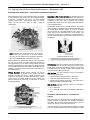
Carburetion Induction Exhaust Suggestions – Section 5 5.1 Tuning Your Carb for Best Performance – Rochester 4GC Rochester 4GC Carburetors – Information and General Operation Secondary or Full Throttle Operation. At between 42 and 60 degrees of throttle opening, the primary fuel delivery is controlled by the Primary Jets plus the Power Valve opening completely. At this point, the air passing over "Auxiliary Throttle Valve" draws it open (it is spring loaded and sensitive to air passing through it). When designed, the 4CG used as small a venturi as possible to keep air velocity high and as such allow efficient metering of the fuel. Conceptually, the 4CG is two 2CGs welded together, back to back – much like two carbs in a Tricarb setup. You will find 4CG carbs on 1964 – 1966 V8 Oldsmobiles. The Auxiliary Throttle Valve is located below the "Secondary Venturi Cluster" and between the Float Bowl Assembly and the Throttle Body Assembly (Base). As it opens, air draws fuel out through the "Secondary Metering Jets" (there is no Power Valve on the Secondary side of the system. The speed and opening rate is controlled by a spring located on the side of the Secondary Venturi Cluster whose tension can be adjusted. The Rochester 4GC Carburetor Note: Rochester 2GC carbs utilize many of the 4GC's "primary side" parts and function in the same manner. You may use the instruction and operation information here for the PRIMARY side of the 4GC for the 2GC. Auxiliary Throttle Valve showing the spring which holds tension against the air flow and determines when the valve will open. While certainly not a performance carb by today's standards, the 4GC can be made to perform quite well. Obviously, if stock appearance is not an issue or budget allows, this carb should be replaced with an aftermarket unit – mostly because very few replacement parts are available. Rebuilding kits are available – see the list in the Performance Tuning Section on the following pages. Fuel Metering. Primary fuel delivery amount is determined by the Main Metering Jet size and the spring tension of the Power Valve. Secondary fuel delivery sequence and amount is determined by the Auxiliary Throttle Valve opening point and the Secondary Metering Jet size. Primary Operation. Normal driving, between 42 and 60 degrees of throttle, is handled by the primary side of the carburetor (smaller front bores – called "primaries"). Fuel metering is controlled by the "Main Metering Jet(s)" and the "Power Valve", that adds additional fuel as needed, and which is restricted or opened by a combination of vacuum and spring pressure. 4GC Air Flow. The 4GC carburetor came in 3 CFM sizes, measured by throttle bore: 1.4375" Primary/1.4375" Secondary = 486 CFM 1.4375" Primary/1.6875" Secondary = 553 CFM 1.5625" Primary/1.6875" Secondary = 692 CFM. This is the largest airflow possible with a 4GC. 2GC Air Flow. The GC carburetor came in 2 CFM sizes, measured by throttle bore: 1 ¼" = 250 CFM 1 ½" = 335 CFM. This is the largest airflow possible with a 2GC. Rochester 4GC Carburetors – Performance Tuning 4GC carbs suffer from being passed over for mods during the heyday of muscle cars because the Quadrajet and Holley were better able to handle higher air flow levels. If you are running one, though, our tips can perk them up. If you would prefer to have a professional upgrade or modify your 4GC, Automotion Rochester Carburetor Service, located 4CG Carb with the air horn removed to show jets and power valve location - 91 - Carburetion Induction Exhaust Suggestions – Section 5 Supercars Unlimited, 13980 SW T.V. Highway Suite 5, Beaverton, Oregon 97005 (503) 641-1442. SU has kits for specific year and application starting with 1964. Select the kit for the year and application. www.supercarsunlimited.com. 3. Set Floats. Proper float adjustment is critical to ensuring that the primary and secondary metering jets can meter sufficient fuel. Set the floats according to the procedure found in the Appendix and according to the settings shown in the Chassis service manual for your vehicle. at 837 36th Ave E, Great Falls, MT 59404 (406-453-5395) www.hotrodcarbs.com can provide both rebuilt 4GC carbs and parts for performance applications. If you contact them, give them your application and intensions. Rochester 2GC Users. Those of you big block owners using 2GC carbs (Turnpike Cruiser with 400 and Cutlass Supremes with the 455 2 bbl. engine), and all small block engines through 1972 can follow along as the 2GC utilizes many of the 4GC's "primary side" parts and functions in the same manner. Obviously, there is no "secondary" operation. We will note any differences as appropriate. 4. Choose the Proper Power Valve Spring. At one time there were different power valves available. Today, most kits supply a "medium" spring, if any. Contact AUTOMOTION Rochester Carburetor Service to see if they have an appropriate spring for your usage. 1966 W-30s Running the 2GC. The 2GC carbs in the 32barrel setup are strikingly similar to a stock 2GC, except that the end carbs have no provision for a choke and some other small differences. You may order a reprint of the Dealer Service Manual Complete Tuning Guide for $5.00 (includes postage) and example of the first page is found in the Appendix. 5. Set Choke. Adjust the choke so that on a warm engine that has reached normal operating temperature, the choke is fully open. Step One - Rebuild It. Blueprinting a 4GC or any other carburetor should be started the same way as blueprinting an engine - with complete disassembly and a thorough cleaning. During disassembly, be careful not to lose any of the tiny but important parts. We tend to use either a cupcake tin or a multi-separated plastic container like those that can be found in a kitchen or housewares store, and place the pieces in separate bins as they are removed. If you do this in proper order, the pieces can be reinstalled by reversing the order of removal. 1. Before you start your rebuild, do the following: Check the throttle Body Assembly (Base) and the Float Bowl Assembly and Air Horn mating surfaces with a straight edge to ensure they are not warped. Ensure the floats are not leaking by setting then in gasoline and see if the sink. If they sink they have a hole. Examine all bolts, screws fasteners springs and clips for wear and loss or tension. Most of the spring steel washers will have lost their tension after all these years, replace them with new. Make sure that that the choke assembly is working. Since it usually uses a thermostatic spring, applying some heat to the spring should cause it to expand and unwind. Clean all rods and levers in the choke system to make sure that they do not bind. Follow all adjustment and settings using the owner's manual for your year, make and model. Make any alterations to factory settings as will be shown in this Section. See the Appendix for general settings and adjustments. Step Two – Increasing the Fuel Flow at the Primary Metering Jets. The best place to start is to increase the Primary Jet size. Each 0.001" size increase in jet size is equivalent to a 1% increase in WOT fuel mixture. Richening the Primary Jets may give a better surge off the line, but if one goes too "deep" in jet size changes, the car will slow down. For a baseline, increase the Primary Jet size in one jet size, then go up in jet sizes until the car slows down. Step Three – Increasing the Fuel Flow with the Secondary Metering Jets. Secondary jets can be increased by one or two sizes. Maximize the primary metering jet fuel flow before moving on to the Secondary Jets. As in the primaries, each 0.001" size increase in jet size is equivalent to a 1½-2% increase in WOT fuel mixture. Richening the Secondary Jets will not effect off the line feel if the throttle valve spring is set correctly, however, if one goes too "deep" in jet size changes, the car will slow down when the secondaries are fully open. For a baseline, increase the Primary Jet size first until the optimum performance has been achieved without touching the secondary jets.27 Step Four – Set the Auxiliary Throttle Valve. No matter what you did in the way of rebuilding or modifying – if the Auxiliary Throttle Valve spring wrap is not set correctly, the carburetor will either sag or bog or – most likely -accelerate like a lazy 2 barrel car. The instructions regarding "clock-wise" or "counter-clockwise" assumes that the Auxiliary Throttle Valve is out of the carb and is sitting on the workbench as shown in the picture. First, insert a small screwdriver into the screw slot on the side of the valve as shown. (See arrow on the bottom left in the picture opposite). Note the location of the screw head in relation to the Throttle. Then insert an Allen wrench in the hole on the valve throttle body and loosen the Allen lock screw, while 2. Use a quality rebuilding kit – preferably from one of the following sources: The Carburetor Refactory, 815 Harbour Way South, #5 Richmond, CA 94804 (510) 237-1277 www.carbkits.com. The Refactory has kits for specific year and application starting with the 50's. Select the kit for the year and application. Fusick Automotive Products, 22 Thompson Road, P.O. Box 655, East Windsor, CT 06088 (860) 623-1583. Fusick has more general kits, but they will work. www.fusick.com. 27 - 92 - For 1966 Tricarb units, treat the center carb as the Primaries and the two outer carbs as the Secondaries. Always make sure that the center carb is opening all the way and that you have richened the jets as much as possible before tuning the outer carbs. Carburetion Induction Exhaust Suggestions – Section 5 keeping the screwdriver steady. (See arrow on the top right in the picture below). adjustment position. Tighten the Allen screw and make a note of the position for future reference. The proper Auxiliary Throttle Setting is the additional tension BEYOND the position you just marked (usually ¼ and less than ½ turn counter-clockwise). Remember to tighten the Allen Screw after each adjustment. Auxiliary Throttle Valve showing the means to adjust it. The Allen wrench holds the cam that keeps the setting locked. NEVER TIGHTEN the spring screw more than 1 turn. This will stretch the spring and make future adjustment impossible. Step Five – Test Effect of Adjustments to the Auxiliary Throttle Valve. Accelerate the car @ WOT from a start with the wrap at ½ turn, which we will call the "stock" position. This is your baseline. Now: Decrease the tension in 1/8 turn steps until bog is detected. This usually occurs by only a ¼ turn. If bog is felt immediately, (first run; tighten 1/8 turn). Automatic transmission cars may need more tension than manual transmission cars. Auxiliary Throttle Valve showing means to adjust. Dashed arrow shows position of small screw which sets air valve tension. After you have reached your maximum tension, change your Secondary Jets. Try going richer first, but don't be afraid to go one step leaner too. Turn the screwdriver clockwise to free the Auxiliary Throttle Valve (the butterflies should flop back and forth freely). Tighten the Allen screw momentarily set the tension and wiggle the butterflies to ensure that the Auxiliary Throttle Valve is loose. Now return the screw driver to the slot, then loosen the Allen Screw and turn the screwdriver counter clockwise until the Air Valve just barely closes. (Zero tension). Note the position of the screwdriver. This is your starting When you have base-lined to the best set of Secondary Jets, try readjusting the wrap in 1/8 turns. Throttle valve wrap changes the point at which the secondary mixture is fed to the carb - in the low and mid range of engine speed, so this is why you need to reset the wrap after you've changed the Jets. If you are unsure as to the result, go back to the original ½ wrap and try one step in richer Jets and work from there. - 93 -


![HEMOSPRAY_JCochin 2012_DVD [Lecture seule]](http://vs1.manualzilla.com/store/data/006493407_1-a29ddfac365866d6de4c1f8c515ac468-150x150.png)