1
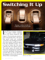
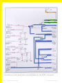
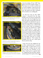
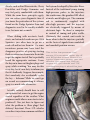
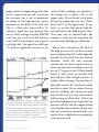
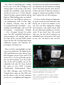
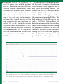
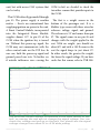
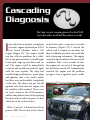
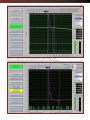
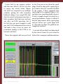
www.mastertechmag.com
February 2011 1
*Details available at your authorized BMW center.
2 Master Technician Online
www.mastertechmag.com
Original BMW Parts
www.bmwusa.com
www.mastertechmag.com
The Ultimate
Driving Machine®
February 2011 3
Contents
Feature Stories
06 Switching It Up
by John Anello
No power window switches on a 2003 Pontiac
Bonneville SSEI
14A Sprinter at the Start
by Kerry Jonsson
While a tall, fuel-efficient delivery truck
answers many commercial needs, it also
presents some new challenges for us in diesel
diagnostics and repair.
28Cascading Diagnostics
by John Anello
The Jeep’s erratic running pointed to the PCM,
but what other work had been done recently?
Cover Story
22This Seat is Occupied
by Kerry Jonsson
In the quest for ever-increasing safety, seat
occupancy detection systems help by giving the
electronics the info needed to determine
how to fire the airbags. That system is
malfunctioning in this 2005 Chrysler
Town & Country. It’s our job to
diagnose and repair what’s wrong.
4 Master Technician Online
www.mastertechmag.com
Christopher M. Ayers, Jr.
President/Publisher: [email protected]
Bob Freudenberger
Editor: [email protected]
John Anello • Steve Campbell • Paul Cortes
Kerry Jonsson • Phil Fournier • Chip Keen
Greg McGoniga • Tony Molla • Tom Nash
Henry Olsen • Matt Ragsdale • Dave Russ
Contributing Editors: [email protected]
Christopher-Michael Ayers
Art Director, Project Mgr.: [email protected]
Joann Turner
Circulation Manager: [email protected]
Editorial, Circulation,
Advertising Sales and Business Office:
Master Technician Magazine
486 Pinecrest Rd. • Springfield, PA • 19064
P.484.472.8441 • F.484.472.7460
Master Technician is published by Master Technician, LLC. The publisher
and editors of this magazine accept no responsibility for statements made
herein by advertisers or for the opinions expressed by authors of bylined
articles or contributed text.
The current Issue of the Master Technician Emag is free to qualified
automotive repair shop owners, managers & technicians. Contact
[email protected] for more information. All other content
is available on a subscription basis. Visit www.mastertechmag.com for
subscription information.
If you have a letter to the editor, a Tech Tip or a story idea,
Email: [email protected], or
visit: www.mastertechmag.com/other/contact_us.
Advertiser Index
February 2011
AIRSEPT.. ................. 25
AutoTechOnWheels....5
BMW..........................2
BASF......................... 37
DAYCO..................... 19
Garage Operator....... 29
www.mastertechmag.com
Henry Rifles.. ..............9
MasterTechnician..... 40
Mercedes-Benz.. ........ 21
NUCAP.. ................... 33
VISION.. ................... 11
Find John at the
2011 VISION
Training Expo!
February 2011 5
Switching It Up
No power window switches on
a 2003 Pontiac Bonneville SSEI
I
by John Anello,
“The Auto Tech on Wheels”
was called in to a shop for a complaint
of no power window operation
on a 2003 Pontiac Bonneville SSEI
(Figure 1). They had already checked the
power and ground feeds at the driver
door master switch and everything
seemed okay. The odd thing was that the
other door windows would not operate
from their individual switches. It was
just hard to believe that this vehicle
could have four bad window switches.
The window motors all worked okay
when power and ground were applied to
each motor individually. The garage was
uncertain where to turn, so rather than
throwing parts at this car they decided to
Figure 1: 2003 Pontiac
call me in for a second opinion.
Bonneville SSEI.
6 Master Technician Online
www.mastertechmag.com
When I arrived at the shop I verified the
complaint by trying each power window
switch and nothing responded. I next
decided to print out a wiring diagram
to familiarize myself with the system
layout and see if I could find something
in common that would affect power
window operation at all four doors,
such as a main power or ground feed. As
I viewed the diagram, I found out that
these were not your everyday “how you
doin’” window switches. Instead, they
were all separate door control modules.
Each module in turn controlled window
motor operation through an internal
window motor driver. Operating the
window switch only created a high/
low signal to command the window up
or down. The switch no longer had to
transmit a power or ground feed to the
window motor directly, which made for
less wear and tear on the switch contacts.
separate low-current battery feeds, so
here too nothing seemed common to all
four door modules. Looking a little closer
at the diagram, I could see that all four
modules did share the same high-current
feed from a 30 Amp circuit breaker, so
this was the first place I wanted to look.
I used my test light and checked each
door module for high-current battery
feed, and they all seemed to be okay. The
tech said that all the wiring checked okay,
and it did, but I still had to see for myself
because you just never know. There have
been many times when techs have used
a logic probe to do a power and ground
check without finding anything, yet a bad
ground or power feed turned out to be the
culprit. They relied on the logic probe’s
ability to light a green or red LED as a
valid check, which only required about 20
mA to light up, but when the ground or
power had to step up to the plate to handle
a a high-current circuit it would lose it’s
connection. This is where a standard test
light, which can load a circuit up to 300
mA, would be a better choice. Keep in
mind, though, that this type of test light
cannot be used on computer circuits
because it can harm them.
I used my Paintbrush function in
Mitchell to color-code the wiring
diagram. I chose green for the grounds,
purple for the high-current circuit
breaker feed, orange and red for lowcurrent battery feed (Figure 2). The
ground feeds for each door module were
at different locations, so it was hard to
believe that the system had four open I discovered that the driver door module
grounds. The rear door modules shared had the ability to communicate with a scan
the same low-current battery feeds, but tool by looking at a data communication
the front door modules had two other wiring diagram (Figure 3), which showed
www.mastertechmag.com
February 2011 7
S w itching It Up
all the onboard controllers on the II scan tool to see if there were any trouble
serial data network linked to the ALDL codes stored in memory that could lead
connector. So, I hooked up my GM Tech me in the right direction. Looking at
Figure 2: Wiring diagram, color coded: Green = Ground; Purple = Highcurrent Circuit Breaker Feed; Orange & Red = Low-current Battery Feed.
8 Master Technician Online
www.mastertechmag.com
“Henry rifles will only be
made in America or they
won’t be made at all.”
Anthony Imperato
President of Henr y Repeating Arms
Henr y .22 Lever Frontier Model with Octagonal Barrel. An affordable, beautiful rifle
with superior tack-driving accuracy. Crafted by American workers for American shooting enthusiasts.
Henr y Golden Boy .22 LR /.22 Mag / .17HMR
Henr y Big Boy .44 Magnum / 45C / .357 Mag
Henr y Acu-Bolt .22 LR / .22 Mag / .17 HMR
Henr y U.S. Sur vival .22 LR
It’s not a prideful boast. It’s a solemn oath from all of us at Henry Repeating
Arms. Every Henry rifle is and always will be made in America by American
workers. Decent, hard working folks like you who take great pride in their work.
We won’t follow the path of other manufacturers who have their products made
overseas and slap their name on them. When you read the rollmark on the barrel
of a Henry, it’s going to read Made in the USA.
We start with only the finest ingredients - gun barrel quality steel from Ohio,
genuine American walnut from Missouri and Iowa, steel castings from Wisconsin
and brass components from Pennsylvania. We manufacture a rifle that you will
be proud to own – with the smoothest action, flawless reliability, and pinpoint
accuracy. Made in America with the same integrity as the Henry rifle President
Lincoln owned.
We are a family owned business and we stand
behind every rifle that leaves our plant. You will
find our customer service second to none, and we’ll
do whatever it takes to guarantee your complete
satisfaction.
We invite you to become part of the Henry
family. Please order our free catalog, which
includes information about our rifles, a list of dealers in
your area and a free Henry decal.
For a FREE color catalog
visit www.henryrepeating.com
or call Toll Free (866) 200-2354
www.mastertechmag.com
February 2011 9
S w itching It Up
Figure 3: Data communication wiring diagram showing all the onboard
controllers on the serial data network linked to the ALDL connector.
10 Master Technician Online
www.mastertechmag.com
the scan tool, I pulled some “U” codes
of interest (Figure 4). The codes U1161,
U1162 and U1163 all pertained to the
driver’s door module’s inability to talk
to the other three door modules. There
was no access for my scan tool to talk
to the other three modules because it
was only able to access the mainstream
controllers all on one network as seen in
the communication link diagram. The
door modules had their own private
UART network that was shared among
them, as can be seen by the blue coloredcoded lines in the Power Window Circuit
diagram (Figure2). This seemed like a
possible culprit if there was damage to
this private network.
According to the diagram, there was
a splice for this private UART network
located under the rug about 14cm from
the left power seat breakout. I had the
shop remove the front driver’s seat,
and as I lifted the rug I noticed a lot of
rust build-up on the floor from a prior
water leak (Figure 5). I next located a
conduit that held the splice internally
wrapped with black electrical tape
(Figure 6). I slowly removed the tape
and was surprised to see a Scotch Lock
Figure 4: “U” codes.
www.mastertechmag.com
February 2011 11
S w itching It Up
connector joining all four UART lines
going to the door modules (Figure 7).
This connector was badly corroded and
was barely making a connection for all
the wires to share. I removed all of the
wires and repaired the splice. Suddenly,
all the windows were working fine.
Figure 5: Lifting the rug, noticing
a lot of rust build-up on the floor
from a prior water leak.
Figure 6: Located a conduit that
held the splice internally wrapped
with black electrical tape.
Figure 7: Removing the tape, a
Scotch Lock connector joined all four
UART lines going to the door modules.
12 Master Technician Online
So, now the recap on this whole
scenario. I discovered that the door
modules were on a private network with
each other and even though they had
their own power and ground feeds and
switch signals, they all refused to operate
when they were unable to communicate
with one another. It was a default built
into the system. What was amazing to
me was why any manufacturer would
use a Scotch Lock to connect these
wires inside a harness running along a
floorboard. Wouldn’t it have been better
to use a solder joint located in a higher
area not so susceptible to water damage?
But, then again, who am I to secondguess the engineers? There’s always the
possibility that this was a field repair
done by another shop.
I hope this story has enlightened you
to better understand how a network,
whether large or small, needs to be in
proper order, or things may not work
the way they were intended to. Just
doing a simple power or ground check
at a component does not always validate
system integrity. Parts replacers beware!
www.mastertechmag.com
EXPO MECHANICAL
COLLISION MANAGEMENT
POWER SUMMIT TECHNICAL
KEYNOTES COMEDY NIGHT
NETWORKING SPOUSE PROGRAM
Expanded in 2011!
Over 85 technical and
management courses
during the 4-day event.
Collision Industry Day
and Collision Expo
Thursday, March 3, 2011
Don’t miss out on this unique and energizing day
designed for collision professionals.
·
·
March 3-6, 2011
KANSAS CITY
EVENT for
Automotive Service
Professionals
www.mastertechmag.com
The
·
·
March 3-6, 2011
Collision Industry Day & Expo: March 3
Conference: March 4-6 Expo: March 4-5
Networking breakfast
Select from multiple breakout sessions
on a variety of hot topics and industry issues
Lunch with keynote speaker
Collision-specific expo featuring vendors
with the latest products and services
Check the website for the latest
schedule and course offerings!
“I have gone from the east coast to the west the coast,
from the windy city to the sunshine state. Dollar for dollar,
ASA MoKan puts on the best training show in the country.”
Gary Walsh, Technician
Hughes Motor Corp, Yonkers, NY
presented by
VISION’S P OWER SUMMI T
MARCH 4 , 2011 • KANSAS CITY
Friday, March 4, 2011
Designed for shop owners and managers, this
premier training day is dedicated to bringing
together some of the industry’s most knowledgeable, most influential and most thoughtful
people to delve into many important topics,
issues and trends that are impacting the independent service marketplace.
SUCCESS LEADERSHIP
POWER PANEL ENERGIZE
PROFITS OPPORTUNITIES
NETWORKING
“I have attended the VISION event many times. The
training is the best of the best. Everyone in the automotive business should be there.”
Terry Steenholdt, AAM
T.D.S. Auto Repair, Sioux Falls, SD
February 2011 13
t
a
r
e
t
n
i
r
p
t
AS
r
a
t
S
the
While a tall, fuel-efficient delivery truck
answers many commercial needs, it also
presents some new challenges for us in
diesel diagnostics and repair.
W
hen you first noticed one
on the road, you probably
thought, “What an unusual
looking vehicle.” And the first service
problem you ran into was likely when
your customer needed brakes. “What,
you want me to bring them down so
you can match them up? Who ever
heard of such a thing?” was a common
customer response to your likely request.
Eventually, parts suppliers learned the
difference between Ate and Bosch, so
that problem smoothed out. When it
comes to diesel diagnosis and repair
issues, however, things are not so easy.
Given this winter’s cold weather, you’ve
probably run into more than your
fair share of “no-starts,” “hard starts,”
and “extended cranks.” You probably
have some experience with American
14 Master Technician Online
by Kerry Jonsson
The PCM won’t open the injectors
unless it sees a signal from the
crankshaft position sensor, which
is mounted in the block on the
driver’s side, by the bell-housing.
You can check resistance, AC
voltage, and scope the signal to
verify that it’s working properly.
www.mastertechmag.com
diesels, such as Ford Powerstroke, Chevy
DuraMax, and Dodge Cummins, and
may feel pretty comfortable with them.
While the same basic principles apply,
you can reduce your diagnostic time if
you know the particulars of the systems
found on the Dodge Sprinter. Scan tool
diagnostics used to be readily available
to us, but now not so much.
When dealing with no-starts, hardstarts, and extended cranks on pre-2004
Sprinters, you often have to go on a
road call and/or tow them in. Or, some
incautious person may have tried the
dangerous practice of spraying starting
fluid or carburetor cleaner into the intake
to get the engine started. You’ve probably
heard the appropriate cautions: Leave
the key on to time out the glow plugs, and
spray while cranking. You may do this
every day, but it’s our duty to inform you
that it’s foolhardy. Suppose, for example,
that somebody else accidentally cycles
the key -- kaboom! While we won’t go
on record as recommending it, silicone
spray is a much safer alternative.
fuel system developed by Mercedes-Benz.
Instead of the traditional pump timing
high-pressure pulses to the injectors,
this works more like gasoline EFI, albeit
at much, much higher psi. The common
rail is continuously supplied with
ultra-high pressure, and the injectors
are electrically triggered by means of
electronic logic. So, there’s a computer
in control of timing and pulse width.
Obviously, that control unit needs to
know when to fire the injectors, partially
on the basis of signals from crankshaft
and camshaft position sensors.
This is the low-pressure fuel
sensor. It’s mounted under the #1
and #2 intake runner. Since it’s a
typical three-wire sensor, you can
monitor the signal line. Key on,
engine off, you should see .5V;
cranking/running it should be just
over one volt.
Actually, nobody should have to add
an explosive fuel source to get the engine
started regardless of the weather. What
engineer would allow a non-starter to be
produced? You just have to figure out
what the problem is. Glow plugs? Fuel
delivery? Injection? These 2.7L vehicles
use a direct-injection, common-rail diesel
www.mastertechmag.com
February 2011 15
A Sprinter at the Start
The fuel injection control unit is
mounted under the driver’s side of the
dash, to the left of the brake pedal. The
crank sensor resides on the driver’s side
of the engine block toward the back
by the transmission bell housing. The
engine will not start at all without the
crank sensor signal. This sensor is an AC
pulse generator. Like most AC pickups,
it uses a two-wire design. A good sensor
will “ohm out” at about 900 ohms
between pins #1 and #2 on the sensor. If
you crank the engine at normal speed,
you should see about one volt AC. If
you’re scoping the signal, expect over 4
VAC peak-to-peak. A normal cranking
rpm would be about 200 to 220. A weak
battery will yield a lower cranking speed
and AC voltage output, so check the The high-pressure sensor is
mounted on the front of the fuel
battery first.
The engine will start without the cam
position sensor signal, but you’ll have a
MIL (Malfunction Indicator Lamp) and
a code will set. If you have extended crank
time, you still need to be concerned with
fuel pressure and the glow plug system.
There are two halves to fuel pressure:
the low-pressure delivery system that
draws fuel from the tank and supplies it
to the next phase, and the high-pressure
pump that is driven off of the camshaft.
The high pressure goes to the fuel rail
and distribution pipes that supply each
injector. Excess fuel is collected in a
16 Master Technician Online
rail. Measure the signal voltage
on the center pin -- you should
see .5V KOEO. During cranking, it
should go to about 1.0V before the
engine starts.
manifold at the rear of the cylinder head,
and returned through the fuel filter, and,
finally, a cooling coil.
The low-pressure system comprises a
mechanically-driven pump that draws
fuel from the tank through a filter. That
is, unless there’s a blockage somewhere.
A clogged fuel filter from additives and
contaminants is a common problem.
Additives intended to improve lubricity
www.mastertechmag.com
Sprinter injectors are of the direct
variety. You can use a “’noid” light
to see if they’re getting a pulsing
signal while cranking, Another test
is to remove the return line and
crank -- fuel should pulse out of
the top. Be careful of the pressure
and fire hazard.
can, over time, settle in the filter and
restrict flow. Dodge recommends
changing the filter every 30,000 miles,
or once a year. The water-in-fuel sensor
is mounted in the bottom of the filter
up to the 2004 model year. It’s a threewire sensor with a 12V reference, 12V
signal line, and ground. The signal line
gets pulled towards ground when there’s
water in the fuel.
www.mastertechmag.com
The purpose of the low-pressure
system is to assure that the high-pressure
system doesn’t run out of fuel when the
engine is under heavy loads. Injection
pressure may be as high as 30,000 psi
(you read that right -- 2,000 BAR!), so
a constant supply of fuel is definitely
needed. A transparent nylon line feeds
the high-pressure pump, so you should
be able to see bubbles if there’s air in the
system. You can check the low-pressure
side by splicing a gauge into this feed
line. You should see about 17 psi at
idle, but it can go as high as 35 to 45 psi
while driving. There’s also a three-wire
low-pressure sensor. On the signal line,
you should see .5V with no pressure,
and about 2.5V at idle. It can go over
3.0V during acceleration.
The high-pressure side uses a threepiston pump that runs at 1-1/3 the speed
of the camshaft. Like those of all other
modern “clean” diesels, it generates
tremendous pressure, which is injected
directly into the combustion chamber.
Full pressure is needed to get the engine
started, and volume is relatively low, so
even small leaks will bleed off enough
pressure to cause a no-start. Be very
careful when inspecting the highpressure side for leaks -- wear safety
glasses and gloves as there’s plenty of
psi to penetrate your skin and give you
a diesel tattoo. We’re not aware of any
February 2011 17
A Sprinter at the Start
gauge outside of engineering circles that
can be tapped into the rail to measure
this pressure, but it can be monitored
by means of the high-pressure sensor
mounted on the front of the fuel rail.
This is a three-wire sensor with a 5V
reference, signal line, and ground. You
can see these voltages on your DRB III
scan tool, but you’ll need the Sprinter
Card, a MUX box adapter, and a special
red-plug cable. The signal line will have
.5V with no significant pressure in the
system. While cranking, you should see
the voltage rise to about 1.0V as the
engine starts. If you do not reach about
875 psi the engine may not start. That’s
about .875V at the signal wire. If you
don’t see at least that much, look for
external leaks in the high pressure lines.
There may also be internal leaks. For
example, a leaky injector may keep the
pressure from building up sufficiently.
There’s also a solenoid at the back of
the high-pressure fuel rail that controls
psi according to load. It’s called, logically
enough, the Fuel Rail Pressure Control
Solenoid, which the fuel injection
control unit can close or open to raise or
lower fuel pressure according to need. It
has an “O” ring at its end. If that should
break, it will create an internal leak
that will not allow enough pressure to
build to allow starting. You may have to
physically remove the solenoid to make
sure this is intact. If you suspect that an
injector is leaking, you can unscrew each
injector line one at a time and install a
ball bearing to block flow. When you
The upper trace is the low-pressure get to the leaking injector, high-side fuel
sensor signal, and the lower trace
is that of the high-pressure sensor. pressure will rise and the engine should
The first step up in both patterns
start the other four cylinders. If you can’t
is the ignition key turned on. The
find any internal or external leaks, you
next step is cranking and running.
may just have a high-pressure pump that
The end of the lower pattern
shows an increase in high pressure is not up to its task.
from acceleration.
18 Master Technician Online
www.mastertechmag.com
www.mastertechmag.com
February 2011 19
A Sprinter at the Start
Dodge has a test for the high-pressure
pump, assuming there are no leaks in
the system. You start by unplugging
the solenoid and checking fuel pressure
while cranking. The engine will not
start, but you should see about 800psi on
your scan tool, or .8 volts on the highpressure sensor signal wire. Your DMM’s
display rate may be too slow to give you
an accurate reading, so you might want
to use a graphing multi-meter, or a lab
oscilloscope to watch the voltage. You
should see a steady signal above .9V. You
may see it spike over 1.0V, but then drop
down. The drop indicates that the pump
cannot maintain pressure, or has a weak
piston. This pressure drop will keep the
engine from starting, and you’ll have to
replace the high-pressure pump. We’ve
noticed that they may start to become
questionable at between 90,000 and
100,000 miles.
Of course, the glow plug system can
cause a starting issue. On pre-2004
models, the glow plug controller is under
the battery tray. It has three connections:
a battery power cable, a six-pin connector
with five wires (one for each glow plug),
and a two-wire connector (one wire
is ground, and the other is the signal
from the fuel injection control unit for
how long to energize the plugs). If you
want to measure the resistance of the
glow plugs, simply unplug the six-pin
20 Master Technician Online
connector and check ohms between each
pin on the connector and an engine or
battery ground. You should see about 1
ohm. These are “pencil” type glow plugs,
which heat up very quickly. The draw for
each is about 20 amps. If you measure the
current on all of them, you will normally
see 75 to 100 amps depending on how
cold the temperature is.
The signal from the fuel injection
control unit to the glow plug controller
starts off at 10 to 11 volts with the key on
and the engine off. A “wait-to-start” light
will come on in the instrument cluster.
The CTS (Coolant Temperature Sensor)
signal is used to determine how long the
glow plugs are energized. The signal will
then change to an inconsistent square
wave. This is normal as the glow plugs
are still pulsed on the first few seconds
the engine is running to help with
combustion on a cold engine. You can
unplug the CTS to get maximum glow
plug time from the controller -- be aware
that the electric cooling fan will come on
as a fail-safe when you do this.
Starting problems can be tricky, but
the more you know about the systems
involved the more efficient you’ll be at
troubleshooting. Sprinters are typically
fleet vehicles, so any downtime is costing
your customers money. A fast and
accurate diagnosis will keep them happy
with you. What more could you want?
www.mastertechmag.com
FIRE...
. . . on all eight with www.startekinfo.com.
Mercedes-Benz USA Dealer Workshop Services is the source for all the technical
information needed to support, service, and maintain Mercedes-Benz vehicles.
Mercedes-Benz workshops rely on DWS products and services for getting jobs
done quickly and more efficiently. Our products include:
s STAR TekInfo with WIS-net (Workshop
Information System)
s Electrical Troubleshooting Manuals
s Installation Instructions
s Technical Bulletins
s Campaigns
s Mercedes-Benz Special Tools
s
s
s
s
s
s
s
Maintenance Manuals and Sheets
STAR Service Manual Library CDs
WIS and DAS software updates
Star Diagnosis System (SDS)
Operator’s Manuals and COMAND Manuals
Mercedes-Benz Equipment
Inventory of technical publications
STAR TekInfo
Dealer Workshop Services
Engineering Services,
Mercedes-Benz USA, LLC.
www.mastertechmag.com
February 2011 21
T h i s Seat is Occupied
“This Seat
Is Occupied”
by Kerry Jonsson
In the quest for ever-increasing safety, seat
occupancy detection systems help by giving
the electronics the info needed to determine
how to fire the airbags. That system is
malfunctioning in this 2005 Chrysler Town &
Country. It’s our job to diagnose and repair
what’s wrong.
W
e’ve all had to keep pace
with
rapidly-advancing
technology,
perhaps
especially so with new developments in
automotive safety. It seems that every
year or so a new airbag gets added -driver’s side, passenger’s side, dual-stage,
side, curtain airbag, knee bolster, etc.
These measures have reduced fatalities
and serious injuries, and their resultant
medical costs. But they’ve also been
known to kill. Small children and frail
elderly people sometimes can’t survive
the full force of a deploying airbag. For
years, the only defense was to relegate such
passengers to the back seat. Now, airbag
technology has advanced to the point that
22 Master Technician Online
occupant detection systems measure the
weight of the passenger and determine if
and how the airbags should be fired.
The primary code led us to
diagnose a bad seat belt
tensioner, but the second
code directed us to a relatively
new item added in 2005, the
Occupancy Classification Module.
www.mastertechmag.com
But what if something goes wrong?
In the past, we’ve had to diagnose bad
airbag squibs, crash sensors, and clocksprings, but a problem in the detection
system was new to us. A 2005 Chrysler
Town & Country came in with the airbag
light on. While pulling codes, we realized
that there are two different systems we
can communicate with. On this Town
& Country, Chrysler used an ORC
(Occupant Restraint Controller -- a.k.a.
Airbag Control Module), and an OCM
(Occupancy Classification Module
-- a.k.a. Occupant Sensor). In earlier
years, the ORC controlled both driver’s
and passenger’s side airbags solely on
the basis of the seat belt buckle switch
status. In 2005, the OCM got input from
additional sensors that monitor the
passenger’s side front seat.
Since we had a warning light, our first
step was to pull codes. We looked in the
ORC and found two codes: Driver’s Seat
Belt Tensioner Circuit Open, and OCM
Active DTCs. On this particular model,
the seat belt tensioner is on the buckle
side of the belt assembly, not on the
adjustable belt side. We then checked
for codes in the OCM. Occupant
Classification Undetermined Status,
No ORC Messages and OCM Data
Transfer Error came up. The ORC code
for the driver’s side seat belt tensioner
circuit was a straightforward diagnosis.
www.mastertechmag.com
Chrysler has a one-ohm resistor tool that
you substitute for the tensioner or airbag
circuit. You then clear the codes and see
if they come back. If they do, you have a
wiring or control unit problem. If they
don’t, replace the seat belt tensioner.
Of course, before doing any diagnostic
or repair work you must disconnect the
battery for at least two minutes to be
safe. You can then unplug the airbags
and tensioners and replace them with
the one-ohm load simulator to test for
codes. If you don’t have this special
tool, you can also check resistance on
individual wires between the ORC and,
in our case, the driver’s side seat belt
The OCM module is located under
the front passenger seat cushion.
It gets voltage from the Front
Control Module, and relies on
both a weight sensor and a seat
belt tension sensor to determine
how the passenger’s side airbags
should be fired.
February 2011 23
T h i s Seat is Occupied
tensioner squib. Keep in mind that there
are shorting bars in the ORC computer
connector. When it’s unplugged the two
wires for each squib are shorted together
to prevent accidental firing. If you
measure resistance between these wiring
pairs you should see continuity, which is
normal. This vehicle ended up needing
the driver’s side seat belt buckle, but we
had other fish to fry.
Profe
Pro
Turne
control the airbag warning light. What it
does is monitor if someone is sitting in
the passenger side seat and reports this
information back to the ORC, which is
in charge of deployment. These modules
communicate through a single-wire PCI
bus. We wanted to verify that this wire
was not shorted to power or ground, or
open. We checked resistance from pin
#15 of the ORC and pin #8 of the OCM
and measured just under ¼ of an ohm.
TurD
Prevent
Preve
The three codes found in the OCM still
turned on the light. These codes all dealt By putting a lab scope on the
with the passenger’s side airbag system, communication wire, we could see if
the heart of which is the OCM module. there was communication, or if there
This module doesn’t fire the airbags, or was interference from other voltage
ProBle
ProBlem
Lubricant d
Lubricant drains
dow
a/c compre
a/c compressor’s mo
soluTio
soluTion
Rotate the
Rotate theTool,
compress
before
Tool, before attachin
feaTure
feaTures>> Fits all
>> Uses a
>> Fits all compress
By watching the oscilloscope pattern of the PCI bus we could easily
>> Won’t s
Uses a standard
determine that there was communication among control units.>>The
bus links many modules, so it was possible that some other unit was
>> Won’t slip, and al
interfering with communications. That should have flagged some other
communication code, however.
24 Master Technician Online
www.mastertechmag.com
essional ComPressor
ofessional
ComPressor
er
Tool™
New!
rner
Damage
toLeaks
New Compressors!
FixTool™
Line
®
®
®
®
Increase Your repaIr revenue & customer satIsfactIon
In 5 Minutes
ent Damage
to New Compressors!
Before PlaCing The
Before
PlaCing
BelT on
The The
BelT on The
ComPressor
probLeM
SoLution
ComPressor
Problem
4PMVUJPO
use
The
Line SpLice - new Metricuse
SizeS
The coMpreSSor Guard
ComPressor
ComPressor
Turner
Tool™!
Tool™!
LineTurner
Splice
STOP!
STOP!
t %BNBHFE-JOFT
t 1JOIPMF-FBLT
Fix
Leaks in 5 Minutes!
t $SPTTUISFBEFE+PJOUT
t 1SPWFO4FBMJOH5FDIOPMPHZ
t /P-JOF3FNPWBM
t 3FTJTUT5PSTJPOBM7JCSBUJPO
>>click here for more information
$POOFDUTMJOFTPGEJòFSFOUEJBNFUFS'JUT BOEMJOFT
Fits in tight
spaces
em
stoP CoMPressor CoMebaCks!
>>click here for more information
kits avaiLabLe For:
patent(Crown
pending
Honda (Crv) trs090 & Hs110 Ford 10s20F
victoria)
patent pending
10Pa-17 (import)
GM (r4 & H-series)
Ford (Fs-10 & Fx-15)
Chrysler (a590 & C171)
TURNER
TURNERTOOL!
TOOL!
Shown here larger than actual size
www.airsept.com 800.999.1051 678.987.0500
drains down during warehouse storage leaving an
wn during warehouse storage leaving an
essor’s moving
unprotected
at initial startup.
d440aparts
r134a
Leak detector
oving parts unprotected at initial startup.
ion
FinD sMaLL reFriGerant Leaks Fast!
J2791-CertiFieD
>>click here for more information
compressor 2 turns using the Compressor Turner
2 turns the
using
the
Compressor
Turner
esor
attaching
drive
belt
to the compressor.
ng the drive belt to the compressor.
coMpreSSor turner tooL
Prevent DaMaGe
to new CoMPressors!
ReCommeNDeD
By
ReCommeNDeD By
ComPressor
manufaCTurers
ComPressor
>>click here for more information
manufaCTurers
es
l compressors with a threaded opening in the clutch hub including R, H, and V series compressors
standard 19mm (3/4”) wrench
sors with a threaded opening in the clutch hub including R, H, and V series compressors
FaSteruse
recycLe
Guard
slip, and allows
of greater
torque than a spanner wrench
19mm (3/4”)
ProteCtwrench
a/C serviCe MaCHines
tranSGuard tranSMiSSion FiLter
FroM seaLant & Debris
ProteCt transMission rePairs FroM Debris
llows use
of greater
torque
than a spanner wrench
>>click
here for more
information
SKU
Description
Available
204042
In Stock
COMPRESSOR TURNER TOOL
www.mastertechmag.com
February
2011 25
call
1-800-999-1051
or 678-987-0500 to order >>www.aIrsept.com
SKU
Description
Available
T h i s Seat is Occupied
or ground sources. We did see a 7.1
to 7.5V square wave with the ignition
key on. This meant the wires were not
shorted and the control units could
communicate with each other. If there
was a communication problem between
these two units, it could be because
one of the units was malfunctioning,
or some other control unit was putting
out erroneous data and confusing the
others. We decided to check codes in
the other control units on the PCI bus,
but didn’t find any that dealt with a loss
of communication. So, we concluded
that the communication problem was
isolated between the ORC and the
OCM units.
We suspected the OCM module because
the first code (Occupant Classification
Undetermined Status) suggested that it
may not be functioning properly. The
second code (No ORC Messages) meant
that the OCM could not communicate
with the ORC even though we could see
the communication on the PCI bus. The
final nail in the OCM coffin was the last
code -- OCM Data Transfer Error. We
knew the communication wire was okay,
so the OCM itself must have been causing
the problem. We wanted to be sure that
there were no other outside influences
causing the OCM to not work properly.
You should always check powers and
grounds before replacing any control
Looking at this weight sensor signal, we see about 4V volts with
the ignition key on. The voltage dropped to about 1V with 185lbs in
the seat. You can watch this signal voltage with a DMM as well.
26 Master Technician Online
www.mastertechmag.com
unit, but with newer CAN systems that OCM to fail, we decided to check the
can be tricky.
two other sensors that provide inputs to
the OCM.
This OCM is directly grounded through
pin #5. The power supply is another
The first is a weight sensor in the
matter -- there’s no conventional fuse bottom of the passenger seat. It is a
supplying ignition-on power to the unit. bladder type sensor with three wires for
A Front Control Module, incorporated reference voltage, signal, and ground.
into the Integrated Power Module, The reference is 5V and comes from pin
supplies almost 11V to pin #9 of the #7. The signal comes in on pin #6 and
OCM when the ignition key is turned changes with the weight applied to the
on. Without this power-up signal, the seat. With no weight, you should see
OCM may not communicate with the about 4V, and with a 185 lb. man in the
other control units on the PCI bus. In seat the signal drops to just about 1V.
our case, both the power-up signal and In other words, the greater the weight,
ground passed our tests. To further see the lower the signal voltage. If you have
if outside influences were causing the codes for this sensor, refer to TSB #08-
The seat belt tension sensor is mounted in the lower mount of the
belt, so moving the reel will not change the signal voltage. You can
check the voltage and pull up on the belt. You should see the signal
voltage change from about 1V to 4.3V while pulling.
www.mastertechmag.com
February 2011 27
T h i s Seat is Occupied
001-04 on passenger side airbag safety
issues and aftermarket parts, such as an
add-on cushion, that can interfere with
proper sensor operation.
The second is the Belt Tension Sensor.
This component also uses a threewire design. The 5V reference comes
from pin #16 of the OCM, and isn’t
shared with that of the weight sensor.
The ground is also separate and comes
through pin #14. The belt tension signal
comes in on pin #4. With no tension on
the belt, you should see just under 1V
on the signal line. Pulling the belt out
of the B-pillar mount will not cause the
signal to change. The sensor reads the
tension on the mount side at the base of
the B-pillar. Grab the belt near the base
and pull up. You should see the signal
rise to about 4.3V.
Since the sensors were functioning
properly, our repair was going to be the
installation of a new OCM. It’s mounted
on the underside of the passenger seat
cushion, and is fairly easy to get to. Even
though it’s a control unit, it doesn’t
need to be programmed or coded when
installed. However, it is not just plugand-play, either. You will have to calibrate
the weight sensor after installing a new
OCM. With your DRB III/Star Scan, or
equivalent, you can calibrate the weight
sensor, but you are going to have to
throw some weight around. It is a threestage process. You start with an empty
seat. You then put 37.5 lbs. on the seat.
In the next step you add an additional
10.6 lbs., and, finally, 52.5 lbs.
With a total of five codes in this Chrysler
airbag system, we needed to make the
customer aware of the hours of diagnostic
time that would be needed to be accurate
and precise with our conclusions. We
must be bold enough to ask for an
honest amount of diagnostic time so we
don’t paint ourselves in a corner. During
that time we need to perform all of the
testing we can so we can make come to
an educated conclusion. We know. With
all the new systems springing up these
days, that’s easier said than done.
Share MasterTechnician
with a friend!
Get an extra 45 days,
FREE Access, when you
“Tell a Friend.”*
*N ew registration subscribers
must have valid Email.
*Tell your Friend to enter
“friend:(your user ID)” into the
promocode section at sign up.
*Promotion valid through June 2011
28 Master Technician Online
www.mastertechmag.com
A N e w I N d u s t ry s tA N dA r d
IN
s h o p M A N Ag e M e N t s o f t wA r e .
EMPOWERMENT:
Control your business
Own the software and your data
Connect & communicate with your PC based shop equipment
Order parts electronically from vendors of YOUR choice
Import labor times from ALLDATA and others
Get the answers you need from GO’s unique reports
BRAGGING RIGHTS:
Regular updates & basic support for one low
monthly fee.
Continuous review and refinement from IATN,
GO Users Forum.
Selected as the exclusive shop management
software for the AAIA Shop Of Tomorrow.
See “Empowerment” above
Visit www.garageoperator.com
for more information.
www.mastertechmag.com
www.mastertechmag.com
February 2011 29
Cascading
Diagnosis
by John Anello, “The Auto Tech on Wheels”
The Jeep’s erratic running pointed to the PCM,
but what other work had been done recently?
I
was called in to a shop for a complaint
of erratic engine operation on a 2007
Jeep Grand Cherokee with a 5.7L
engine (Figure #1). The engine would
run fine with no problems for a while,
but at any given moment it would begin
to abruptly surge up and down and cut
out. The engine could be immediately
restarted and would run perfectly again
until the next episode. The shop had
installed high-performance spark plugs
and ignition coils a few weeks earlier,
but there were no drivability complaints
at the time. The shop even put the old
ignition coils back into the engine, but
the problem still remained. There were
no codes stored in the PCM memory,
and the shop did not want to start playing
Russian roulette with auto parts, so they
called me in for tech assistance.
to check for codes -- none were recorded
in memory (Figure #2). I started the
vehicle and it seemed to run okay, but
then it suddenly started to run erratically
with a bouncing tachometer. The engine
seemed to dip in and out with a near-stall
condition. After a few seconds of this,
the engine just cut out as if the ignition
key had been turned off. I immediately
restarted the engine and the problem
was gone. I ran it again for quite a while
Figure 1: 2007 Jeep Grand Cherokee
When I arrived, I attached my Escan
generic OBD II scan tool to the vehicle
30 Master Technician Online
www.mastertechmag.com
and could not reproduce the problem.
It was as if the crank or cam sensor was
giving an erratic signal, or the PCM had
an internal board issue. I could no longer
reproduce the problem, so I offered the
garage a free opinion: Try a new crank
sensor due to their high failure rate. It
would be a cheap fix if it worked.
The shop called back the next day
and told me that the crank sensor did
not fix the problem and that they had
rechecked all the PCM power and
ground feeds. The shop was willing to
try a new PCM since the problem was
so intermittent and everything seemed
to lead to an erratic computer. I agreed
to program the new PCM for them in
hopes that the problem would go away.
I could not think of anything else that
could cause such an erratic problem.
I went there the next day after the new
PCM was delivered to program it with
new software and configure it to match
the vehicle. I started the Jeep and it ran
fine for the first 15 minutes, but then it
went back into its dance. At this point I
got that feeling we all get when we realize
that there is an expensive unneeded part
installed that someone has to take the
blame for. At this point, the shop I were
both now married to the vehicle, and we
Figure 2: EScan shows no codes in memory
www.mastertechmag.com
February 2011 31
C a scading Diagnostics
had to find the problem or this PCM was engine cut out. This had to be a loss of
going to be this evening’s meal.
power or ground to the PCM, or possibly
a reference voltage feed momentarily
I knew my timeframe was short for shorting to ground because the PCM
finding the culprit because I had no idea was shutting down operations at the
how long the problem was going to stick same time as it decided to no longer
around. I quickly placed my Escan tool communicate with my scan tool. The
on the vehicle and graphed some PCM only way I was going to nail this problem
parameters to see if anything looked would be with a multi-trace scope to
unusual or out of range (Figure #3). watch as many signals as I could before
I was monitoring the rpm, MAP and this problem decided to go away.
TPS sensors and could see the engine
rpm going into an idle roll. But then
I used my eight-trace Escope and
something unusual happened -- I lost quickly selected six main items that
communication with the PCM as the would help me pinpoint the problem
problem got worse (Figure #4), then the using my different colored leads as
Figure 3: Graphing data parameters
32 Master Technician Online
www.mastertechmag.com
NEW TECHNOLOGY FROM THE INDUSTRY LEADER
IT’S QUICK, QUIET AND COOL.
SNAPS IN PLACE AND HOLDS TIGHT.
REDUCE NOISE + REDUCE HEAT = REDUCE COMEBACKS
No brake job is truly complete without the NU-LOK Piston Cushion.
NUCAP, the Brake Technology Company, has developed this
revolutionary new product to create a barrier between the piston surface
and brake pad. The NU-LOK Piston Cushion is a snap to use. It improves
noise control while extending caliper life.
Keep quiet, keep cool with the NU-LOK Piston Cushion – improve
performance in everyday braking conditions and during extreme
braking maneuvers.
For A QUICK AND CoST
EFFECTIVE SoLUTIoN To NoISY
BrAKES orDEr NoW AT:
www.PISTONCUSHION.COM
Figure 4: Loss of scanner communication
www.mastertechmag.com
Noise PreveNtioN
The hi-temp rubber coated
NU-LOK Piston Cushion, based
on floating design principles, is
designed to absorb movement
and minimize piston wear. It
integrates with the existing brake
pad shim to further reduce noise
on any braking system.
Heat DissiPatioN
The NU-LOK Piston Cushion
also acts as a heat shield
between the pad/rotor and the
caliper. This reduces brake fluid
temperature for better pedal
feel, more controlled stops and
longer fluid life. The cushion
also prevents caliper boots
from overheating and possibly
melting.
February 2011 33
C a scading Diagnostics
follows: white for PCM battery feed,
blue for PCM ignition feed, red for PCM
Auto Shutdown Down relay feed, purple
for ASD relay coil driver, yellow for 5V
reference, and green for PCM ground.
As the engine started to run erratically,
I captured my first event (Figure #5).
I could see that the ASD relay driver
momentarily was released by the PCM
under 50ms, but I never lost my 5V
reference, or my powers and grounds. It
was as if something was telling the PCM
to let go of the ASD relay coil, so I now
had to dig a little deeper. I wanted to see
if I was losing a cam or crank signal, so
I captured two more events using my
green lead for the cam signal (Figure #6)
and my yellow lead for the crank signal
(Figure #7). Neither waveform pattern
showed a loss of cam or crank signal when
the ASD relay was being released, but the
tachometer was definitely following the
cutting in and out of the engine.
I had an eight-trace scope, so it was
to my advantage to monitor all eight
ignition coil primary circuits to see if any
coil trigger was dropping out. I moved all
my leads to the coil drivers and continued
to monitor the engine’s operation. Today
was my lucky day because this problem
was only getting worse and it decided to
Figure 4: Loss of scanner communication
34 Master Technician Online
www.mastertechmag.com
Figure 5 (Above): ECM releasing ASD relay coil
Figure 6 (Below): Checking for loss of cam signal
www.mastertechmag.com
February 2011 35
C a scading Diagnostics
I have done so far has lead me to erratic
PCM operation and I just could not
pinpoint the cause. I could see what
the PCM was doing, but what was its
reasoning? Bernie basically wanted me
to go back to my scope and look below
the zero line for any secondary voltage
kickback that could cause a PCMreset condition. That’s when outside
noises penetrate the PCM through
electromagnetic
interference
and
disrupt its normal algorithms, making it
momentarily skip a beat. The engine in
I decided to call Bernie Thompson no way or fashion had an engine misfire
from Automotive Test Solutions just get due to a bad ignition coil or spark plug,
his opinion on things because everything but it still seemed like a logical possibility.
stick around and give me a joy ride. When
I captured another event (Figure #8), I
was surprised to see that I was losing all
eight coil drivers at the same time. The
PCM was letting go of the ASD relay coil
and it did not start to trigger the ignition
coils again until about 300ms later. There
was something making this PCM halt all
operations momentarily, or I possibly
had a bad new PCM on hand. It would
not be the first time I have come across a
defective new part.
Figure 7: Checking for loss of crank signal
36 Master Technician Online
www.mastertechmag.com
No matter what kind of car you’ve got in your paint shop, a perfect color match
is always the goal. And that’s where BASF Refinish breaks from the field. Only
BASF offers the COLOR-MAX®3 system, which covers every color category in the
spectrum and only uses chips sprayed with authentic BASF Refinish paint—not
printed with ink. So you are assured a precise match the first time, every time,
reducing comebacks and increasing productivity. And remember, BASF Refinish
coatings are already approved for use by most major OEMs in North America.
For the kind of color matches that also match your customers’ expectations, call
your local BASF distributor at 1-800-825-3000 or visit www.basfrefinish.com.
www.mastertechmag.com
FooseTM, Chip FooseTM, Foose DesignTM and the Chip Foose signature are
registered trademarks of Foose Design Inc. and used with permission.
February 2011 37
© 2009 BASF Corporation.
C a scading Diagnostics
I went back to my primary pattern
and this time lifted it off the zero line
to expose any activity below (Figure
#9), and I was surprised to see multiple
cylinders getting hit with secondary
kickback voltage. Cars using PCMs that
directly control coil primary may have a
little secondary kick that may not have
any effect on PCM operation, but if
the kick does get great enough it could
give the PCM a momentary heart attack
and make it skip a beat, or, worse, do
permanent damage to the PCM or an
internal coil driver.
in, but I was not so sure about the spark
plugs. I had the shop pull a spark plug to
get a look at what was currently installed
in the engine. I then compared that
spark plug to the original (Figure #10),
and there was something funky about it.
It had a triangle-shaped electrode for a
special performance feature it offered. I
had the shop remove all the spark plugs
and put factory spec spark plugs back
in. Once this was done, the problem was
completely resolved.
I can only tell you that I was taken aback
by this turn of events. It is just so hard to
I knew the original coils were put back believe that a company could manufacture
Figure 8: Scoping all 8 coil drivers
38 Master Technician Online
www.mastertechmag.com
Figure 9: Secondary KV spikes present
a spark plug for performance purposes
without any regard to its effects in a coilover-plug environment. The problem it
created mimicked a failed PCM that any
tech would have automatically changed in
the field. There were no codes, no sensor
failures, or wiring issues. A multi-trace
scope would have to be used to find a
cascading effect of events that would point
you in the right direction. I own many
one-, two- and four-trace scopes, but with
so many circuits involved with onboard
control modules today, it sometimes
makes more sense to use a bigger net to
throw at a problem rather than fishing
Figure 10: Comparing performance
around with only a few hooks.
spark plug
www.mastertechmag.com
February 2011 39
Repair and Business Solutions for
Professional Automotive Technicians & Shop Owners
mastertechmag
www.
.com
Digital Magazines
Hybrids & Everything “Green”
Tool & Equipment Review
Weekend Warrior : Fun Stuff
Check out what’s coming in 2010
Register: For sixty days free access
Volume 2 | Issue 1
Inside the Insider
Small Business Relief
The new Health Care Act
will affect nearly every
small business. The main
provisions of the Act roll out
over the next four years.
page 1
Protect Your Company,
and Limit Your Risks...
There are strategies that
a business may take in
advance to maximaize the
protection of its interests
and limit its risks.
page 1
The Three R’s
keeping your current
technician workforce
productive and happy. It
all begins with the 3R’s—
Recruitment, Retention
and Recognition.
page 4
Forecast:
Cloud Computing
The who, what, where,
when, and hows you need
to know...
Small Businesses May
See Some Relief in the
New Health Care Act
Questions/Comments:
Contact Us via Website or
Call Chris Ayers Jr
484.472.8441
by Mary Louisa L’Hommedieu, Esq.
The new Health Care Act will affect nearly every small
business. The main provisions of the Act roll out over
the next four years, with the major changes occurring
in 2014. Most notably, beginning in 2014, businesses
with more than 50 employees (or full-time equivalents)
must provide affordable health insurance for their
employees or face penalties. Businesses with fewer
than 100 employees will be permitted to participate in
insurance exchanges, to be set up in each state, where a
pooling of resources should drive the costs of insurance
down. And while small businesses are not required to
offer insurance for
their employees, the
Act provides strong
incentives for them
to do so.
Until the Small
Business
Health
Options Programs or SHOP insurance
exchanges become
page 12
40 Master Technician Online
www.mastertechmag.com
www.mastertechmag.com | April 2010
1