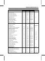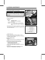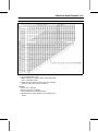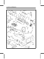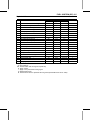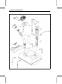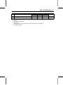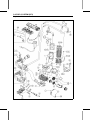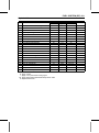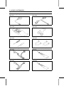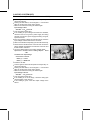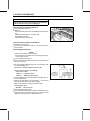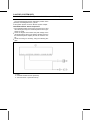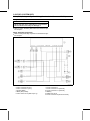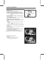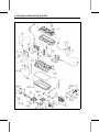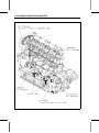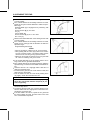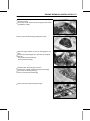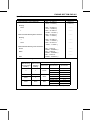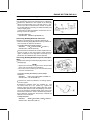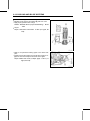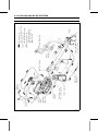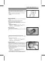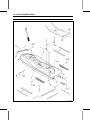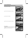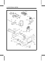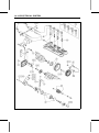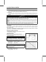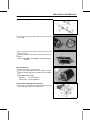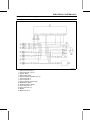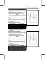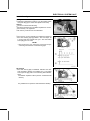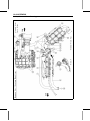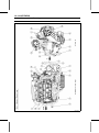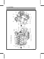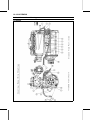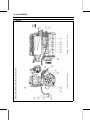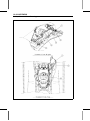
1
ULTRA 250X
JET SKI Watercraft
Service Manual
®
is a trademark of Kawasaki Heavy Industries, Ltd. registered in U.S.A., Japan,
Austria, Benelux, Sweden, Denmark, Switzerland, France, Canada, Finland, Norway, Greece, Italy,
U.K., Portugal, Thailand, and Taiwan.
KAWASAKI JET SKI® is a trademark of Kawasaki Heavy Industries, Ltd. registered in Australia.
Quick Reference Guide
This quick reference guide will assist
you in locating a desired topic or procedure.
•Bend the pages back to match the
black tab of the desired chapter number with the black tab on the edge at
each table of contents page.
•Refer to the sectional table of contents
for the exact pages to locate the specific topic required.
General Information
1 j
Periodic Maintenance
2 j
Fuel System (DFI)
3 j
Engine Lubrication System
4 j
Exhaust System
5 j
Engine Top End
6 j
Engine Removal/Installation
7 j
Engine Bottom End
8 j
Cooling and Bilge Systems
9 j
Drive System
10 j
Pump and Impeller
11 j
Steering
12 j
Hull/Engine Hood
13 j
Electrical System
14 j
Storage
15 j
Appendix
16 j
ULTRA 250X
JET SKI Watercraft
Service Manual
®
All rights reserved. No parts of this publication may be reproduced, stored in a retrieval system, or
transmitted in any form or by any means, electronic mechanical photocopying, recording or otherwise,
without the prior written permission of Quality Assurance Division/Consumer Products and Machinery
Company/Kawasaki Heavy Industries, Ltd., Japan.
No liability can be accepted for any inaccuracies or omissions in this publication, although every possible
care has been taken to make it as complete and accurate as possible.
The right is reserved to make changes at any time without prior notice and without incurring an obligation
to make such changes to products manufactured previously. See your JET SKI® watercraft dealer for the
latest information on product improvements incorporated after this publication.
All information contained in this publication is based on the latest product information available at the time
of publication. Illustrations and photographs in this publication are intended for reference use only and may
not depict actual model component parts.
© 2006 Kawasaki Heavy Industries, Ltd.
Second Edition (1):Oct. 4, 2007 (K)
LIST OF ABBREVIATIONS
A
ABDC
AC
ATDC
BBDC
BDC
BTDC
°C
DC
F
°F
ft
g
h
L
ampere(s)
after bottom dead center
alternating current
after top dead center
before bottom dead center
bottom dead center
before top dead center
degree(s) Celsius
direct current
farad(s)
degree(s) Fahrenheit
foot, feet
gram(s)
hour(s)
liter(s)
lb
m
min
N
Pa
PS
psi
r
rpm
TDC
TIR
V
W
Ω
pound(s)
meter(s)
minute(s)
newton(s)
pascal(s)
horsepower
pound(s) per square inch
revolution
revolution(s) perminute
top dead center
total indicator reading
volt(s)
watt(s)
ohm(s)
COUNTRY AND AREA CODES
AT
CA
CAL
CH
DE
Austria
Canada
California
Switzerland
Germany
EUR
GB
US
WVTA
Europe
United Kingdom
United States
Whole Vehicle Type Approval
MAINTENANCE AND ADJUSTMENTS
Maintenance, replacement, or repair of the emission control devices and systems may
be performed by any marine Sl engine repair establishment or individual.
EMISSION CONTROL INFORMATION
Fuel Information
THIS ENGINE IS CERTIFIED TO OPERATE ON UNLEADED PREMIUM GRADE GASOLINE
ONLY.
A minimum of 90 octane of the antiknock index is recommended. The antiknock index is posted
on service station pumps.
Emission Control Information
To protect the environment in which we all live, Kawasaki has incorporated an exhaust emission control system in compliance with applicable regulations of the United States Environmental
Protection Agency.
Exhaust Emission Control System
This system reduces the amount of pollutants discharged into the atmosphere by the exhaust
of this engine. The fuel, ignition and exhaust systems of this engine have been carefully designed and constructed to ensure an efficient engine with low exhaust pollutant levels.
Maintenance
Proper maintenance and repair are necessary to ensure that watercraft will continue to have
low emission levels. This Service Manual contains those maintenance and repair recommendations for this engine. Those items identified by the Periodic Maintenance Chart are necessary
to ensure compliance with the applicable standards.
Tampering with Emission Control System Prohibited
Federal law prohibits the following acts or the causing thereof: (1) the removal or rendering
inoperative by any person other than for purposes of maintenance, repair, or replacement, of
any device or element of design incorporated into any new engine for the purposes of emission
control prior to its sale or delivery to the ultimate purchaser or while it is in use, or (2) the use
of the engine after such device or element of design has been removed or rendered inoperative
by any person.
Among those acts presumed to constitute tampering are the acts listed below:
Do not tamper with the original emission related parts.
* Digital Transistor Ignition System
* Fuel Pump
* Spark Plugs
* Throttle Body and Internal Parts
* Fuel Injectors
* ECU
* Supercharger with intercooler & relief-valves
Foreword
This manual is designed primarily for use by
trained mechanics in a properly equipped shop.
However, it contains enough detail and basic information to make it useful to the owner who desires to perform his own basic maintenance and
repair work. A basic knowledge of mechanics,
the proper use of tools, and workshop procedures must be understood in order to carry out
maintenance and repair satisfactorily. Whenever the owner has insufficient experience or
doubts his ability to do the work, all adjustments, maintenance, and repair should be carried out only by qualified mechanics.
In order to perform the work efficiently and
to avoid costly mistakes, read the text, thoroughly familiarize yourself with the procedures
before starting work, and then do the work carefully in a clean area. Whenever special tools or
equipment are specified, do not use makeshift
tools or equipment. Precision measurements
can only be made if the proper instruments are
used, and the use of substitute tools may adversely affect safe operation.
For the duration of the warranty period,
we recommend that all repairs and scheduled
maintenance be performed in accordance with
this service manual. Any owner maintenance or
repair procedure not performed in accordance
with this manual may void the warranty.
To get the longest life out of your JET SKI®
watercraft:
Follow the Periodic Maintenance Chart in the
Service Manual.
Be alert for problems and non-scheduled
maintenance.
Use proper tools and genuine Kawasaki JET
SKI® watercraft parts. Special tools, gauges,
and testers that are necessary when servicing Kawasaki JET SKI® watercraft are introduced by the Service Manual. Genuine parts
provided as spare parts are listed in the Parts
Catalog.
•
•
•
the procedures in this manual care• Follow
fully. Don’t take shortcuts.
to keep complete records of main• Remember
tenance and repair with dates and any new
parts installed.
How to Use This Manual
In this manual, the product is divided into
its major systems and these systems make up
the manual’s chapters. The Quick Reference
Guide shows you all of the product’s system
and assists in locating their chapters. Each
chapter in turn has its own comprehensive Table of Contents.
For example, if you want ignition coil information, use the Quick Reference Guide to locate
the Electrical System chapter. Then, use the
Table of Contents on the first page of the chapter to find the Ignition Coil section.
Whenever you see these WARNING and
CAUTION symbols, heed their instructions!
Always follow safe operating and maintenance
practices.
WARNING
This warning symbol identifies special
instructions or procedures which, if not
correctly followed, could result in personal injury, or loss of life.
CAUTION
This caution symbol identifies special
instructions or procedures which, if not
strictly observed, could result in damage to or destruction of equipment.
This manual contains four more symbols (in
addition to WARNING and CAUTION) which will
help you distinguish different types of information.
NOTE
This
note
symbol
indicates points of par○
ticular interest for more efficient and convenient operation.
a procedural step or work to be
• Indicates
done.
○Indicates a procedural sub-step or how to do
the work of the procedural step it follows. It
also precedes the text of a NOTE.
Indicates a conditional step or what action to
take based on the results of the test or inspection in the procedural step or sub-step it follows.
In most chapters an exploded view illustration
of the system components follows the Table of
Contents. In these illustrations you will find the
instructions indicating which parts require specified tightening torque, oil, grease or a locking
agent during assembly.
This model, JT1500B, is mounted with a four
-stroke engine with supercharger.
When the JET SKI® watercraft is submerged
and swamped, the four-stroke engine needs
special care and systematic procedure for recovery compared with the two-stroke engine.
Therefore in this manual, such procedures,
which are not shown in SMs for two-stroke
engines, are explained thoroughly to cope with
the cases.
Refer to the section, After submerging in
Chapter 9, Cooling and Bilge Systems for the
summary and detailed procedures.
GENERAL INFORMATION 1-1
General Information
Table of Contents
Before Servicing .....................................................................................................................
Model Identification.................................................................................................................
General Specifications............................................................................................................
Unit Conversion Table ............................................................................................................
1-2
1-10
1-11
1-13
1
1-2 GENERAL INFORMATION
Before Servicing
Before starting to perform an inspection service or carry out a disassembly and reassembly operation on watercraft, read the precautions given below. To facilitate actual operations, notes, illustrations, photographs, cautions, and detailed descriptions have been included in each chapter wherever
necessary. This section explains the items that require particular attention during the removal and
reinstallation or disassembly and reassembly of general parts.
Especially note the following:
Kawasaki Diagnostic System (KDS) Software
KDS software that runs on Windows personal computer (PC) will be available as a diagnostic tool
for watercraft with Kawasaki DFI system.
You need the following items to use the KDS.
Item
KDS Software Version 2.□ (CD-ROM, Updated Version)
Signal Converter
Communication Cable and Cable Adapter
KDS Adapter Cable
P/No.
57001-1503
57001-1504
57001-1470
57001-1696
The connectors for the communication cable and KDS adapter cable are located in the front.
Connect the communication cable to the KDS connector (4-pin) [A] and the KDS adapter cable
between the ignition switch (immobilizer amplifier) lead connectors (6-pin) [B].
Adjustments
Adjustments shall be made in accordance with the Periodic Maintenance Chart or whenever troubleshooting or presence of symptoms indicate that adjustments may be required. Whenever running
of the engine is required during maintenance it is best to have the watercraft in water.
CAUTION
Do not run the engine without cooling water supply for more than 15 seconds, especially
in high revolutionary speed or severe engine and exhaust system damage will occur.
Auxiliary Cooling
An auxiliary cooling supply may be used if the watercraft cannot be operated in water during adjustments. If possible, always operate the watercraft in water rather than use an auxiliary cooling supply.
GENERAL INFORMATION 1-3
Before Servicing
a standard garden hose [A] and a garden hose
• Obtain
adapter [B] as shown.
C: Garden Hose Fitting of Adapter
D: Flushing Fitting of Adapter
E: Thread: Rp 3/4
○Optional part (P/No. 92005-3746) is available as a garden
hose adapter.
the front storage compartment cover.
• Open
Remove
the flushing cap [A] on the brim of the storage
• compartment.
a garden hose adapter [A] onto the flushing fitting
• Screw
[B].
a garden hose [C] to a garden hose adapter and
• Attach
secure the hose clamp [D].
the garden hose to a faucet. Do not turn on the water until the engine is running and turn it
• Attach
off immediately when the engine stops. The engine requires 2.4 L/min (2.5 qts/min) at 1 800 rpm
and 7.0 L/min (7.4 qts/min) at 6 000 rpm.
CAUTION
Insufficient cooling supply will cause the engine and/or exhaust system to overheat and
severe damage will occur. Excessive cooling supply may kill the engine and flood the cylinders, causing hydraulic lock. Hydraulic lock will cause severe damage to the engine. If the
engine dies while using an auxiliary cooling supply, the water must be shut off immediately.
CAUTION
Always turn the boat on its left side. Rolling to the right side can cause water in the exhaust
system to run into the engine, with possible engine damage.
1-4 GENERAL INFORMATION
Before Servicing
CAUTION
Turn the capsized boat clockwise so that the port side always faces downward. Turning
counterclockwise can cause water in the exhaust system to run into the engine, with possible engine damage.
Battery Ground
Before completing any service on the watercraft, disconnect the battery wires from the battery to prevent the engine
from accidentally turning over. Disconnect the ground wire
(–) first and then the positive (+). When completed with the
service, first connect the positive (+) wire to the positive (+)
terminal of the battery then the negative (–) wire to the negative terminal.
Edges of Parts
Lift large or heavy parts wearing gloves to prevent injury
from possible sharp edges on the parts.
Solvent
Use a high flush point solvent when cleaning parts. High
flush point solvent should be used according to directions
of the solvent manufacturer.
GENERAL INFORMATION 1-5
Before Servicing
Cleaning Watercraft before Disassembly
Clean the watercraft thoroughly before disassembly. Dirt
or other foreign materials entering into sealed areas during
watercraft disassembly can cause excessive wear and decrease performance of the watercraft.
Arrangement and Cleaning of Removed Parts
Disassembled parts are easy to confuse. Arrange the
parts according to the order the parts were disassembled
and clean the parts in order prior to assembly.
Storage of Removed Parts
After all the parts including subassembly parts have been
cleaned, store the parts in a clean area. Put a clean cloth
or plastic sheet over the parts to protect from any foreign
materials that may collect before re-assembly.
Inspection
Reuse of worn or damaged parts may lead to serious accident. Visually inspect removed parts for corrosion, discoloration, or other damage. Refer to the appropriate sections
of this manual for service limits on individual parts. Replace
the parts if any damage has been found or if the part is beyond its service limit.
Replacement Parts
Replacement Parts must be KAWASAKI genuine or
recommended by KAWASAKI. Gaskets, O-rings, Oil seals,
Grease seals, circlips or cotter pins must be replaced with
new ones whenever disassembled.
1-6 GENERAL INFORMATION
Before Servicing
Assembly Order
In most cases assembly order is the reverse of disassembly, however, if assembly order is provided in this Service
Manual, follow the procedures given.
Tightening Sequence
Generally, when installing a part with several bolts, nuts,
or screws, start them all in their holes and tighten them to
a snug fit. Then tighten them according to the specified sequence to prevent case warpage or deformation which can
lead to malfunction. Conversely when loosening the bolts,
nuts, or screws, first loosen all of them by about a quarter turn and then remove them. If the specified tightening
sequence is not indicated, tighten the fasteners alternating
diagonally.
Tightening Torque
Incorrect torque applied to a bolt, nut, or screw may
lead to serious damage. Tighten fasteners to the specified
torque using a good quality torque wrench.
Force
Use common sense during disassembly and assembly,
excessive force can cause expensive or hard to repair damage. When necessary, remove screws that have a non
-permanent locking agent applied using an impact driver.
Use a plastic-faced mallet whenever tapping is necessary.
Gasket, O-ring
Hardening, shrinkage, or damage of both gaskets
and O-rings after disassembly can reduce sealing performance. Remove old gaskets and clean the sealing
surfaces thoroughly so that no gasket material or other
material remains. Install new gaskets and replace used
O-rings when re-assembling
GENERAL INFORMATION 1-7
Before Servicing
Liquid Gasket, Locking Agent
For applications that require Liquid Gasket or a Locking
agent, clean the surfaces so that no oil residue remains before applying liquid gasket or locking agent. Do not apply
them excessively. Excessive application can clog oil passages and cause serious damage.
Press
For items such as bearings or oil seals that must be
pressed into place, apply small amount of oil to the contact area. Be sure to maintain proper alignment and use
smooth movements when installing.
Ball Bearing
Do not remove pressed ball or needle unless removal is
absolutely necessary. Replace with new ones whenever
removed. Press bearings with the manufacturer and size
marks facing out. Press the bearing into place by putting
pressure on the correct bearing race as shown.
Pressing the incorrect race can cause pressure between
the inner and outer race and result in bearing damage.
Oil Seal, Grease Seal
Do not remove pressed oil or grease seals unless removal
is necessary. Replace with new ones whenever removed.
Press new oil seals with manufacture and size marks facing
out. Make sure the seal is aligned properly when installing.
Apply specified grease to the lip of seal before installing
the seal.
1-8 GENERAL INFORMATION
Before Servicing
Circlips, Cotter Pins
Replace circlips or cotter pins that were removed with new
ones. Take care not to open the clip excessively when installing to prevent deformation.
Lubrication
It is important to lubricate rotating or sliding parts during
assembly to minimize wear during initial operation. Lubrication points are called out throughout this manual, apply
the specific oil or grease as specified.
Direction of Engine Rotation
When rotating the crankshaft, by hand, the free play
amount of rotating direction will affect the adjustment. Rotate the crankshaft to positive direction (counter-clockwise
viewed from stern sinde).
Electrical Wires
A two-color wire is identified first by the primary color and
then the stripe color. Unless instructed otherwise, electrical
wires must be connected to those of the same color.
Instrument
Use a meter that has enough accuracy for an accurate
measurement. Read the manufacture’s instructions thoroughly before using the meter. Incorrect values may lead
to improper adjustments.
GENERAL INFORMATION 1-9
Before Servicing
Harness Connector
Apply grease [A] on all connectors of harness [B] for water
resistance. Do not apply grease on the only connector of
inlet air pressure sensor.
1-10 GENERAL INFORMATION
Model Identification
JT1500B7F Left Side View
JT1500B7F Right Side View
Hull Identification Number (HIN)
Engine Number
GENERAL INFORMATION 1-11
General Specifications
JT1500B7F ∼
Items
Engine
Type
Displacement
Bore and Stroke
Compression Ratio
Maximum Horsepower
Maximum Torque
Ignition System
Lubrication System
Carburetion System
Starting System
Cylinder Numbering Method
Firing Order
Valve Timing:
Inlet:
Open
Close
Duration
Exhaust:
Open
Close
Duration
Tuning Specifications
Spark plug:
Type
Gap
Ignition Timing
Idle Speed
Compression Pressure
Drive System
Coupling
Jet Pump:
Type
Thrust
Steering
Braking
Performance
†Minimum Turning Radius
†Fuel Consumption
†Cruising Range
Dimensions
Overall Length
4-stroke, DOHC, 4-cylinder, water cooled
1 498 cm³ (91.4 cu in.)
83 × 69.2 mm (3.27 × 2.72 in.)
7.8 : 1
184 kW (250 PS) @7 750 r/min (rpm)
237 N·m (24.2 kgf·m, 174.8 ft·lb) @6 500 r/min (rpm)
Digital transistor
Forced lubrication (semi-dry sump)
FI (fuel injection) MIKUNI AC 60 × 1
Electric starter
Front (bow) to rear (stern), 1-2-3-4
1-2-4-3
15° BTDC
65° ABDC
260°
73.5° BBDC
8.5° ATDC
262°
NGK PMR9B
0.6 ∼ 0.7 mm (0.024 ∼ 0.028 in.)
0° ATDC @1 300 r/min ∼ 8° BTDC @3 000 r/min (rpm)
1 300 ±100 r/min (rpm) -in water
1 300 ±100 r/min (rpm) -out of water
1 190 ∼ 1 799 kPa (12.1 ∼ 18.3 kgf/cm², 173 ∼ 261 psi) @430
r/min (rpm)
Direct drive from engine
Axial flow single stage
6 780 N (692 kgf, 1 524 lb)
Steerable nozzle
Water drag
4.0 m (13.1 ft)
74.5 L/h (19.7 US gal/h) @full throttle
105 km (65.2 mile) @full throttle 59 minutes (3 person)
3 370 mm (132.7 in.)
1-12 GENERAL INFORMATION
General Specifications
Items
Overall Width
Overall Height
Dry Weight:
JT1500B7F
JT1500B8F
Fuel Tank Capacity
Engine Oil
Type
Viscosity
Capacity
Electrical Equipment
Battery
Maximum Generator Output
JT1500B7F ∼
1 195 mm (47.0 in.)
1 150 mm (45.3 in.)
416 kg (917 lb)
410 kg (904 lb)
78 L (20.6 US gal)
API SE, SF or SG
API SH, SJ or SL with JASO MA
SAE 10W-40
5.0 L (5.3 US qt)
12 V 18 Ah
16 A @14 V
†: This information shown here represents results under controlled conditions, and the information
may not be correct under other conditions.
Specifications subject to change without notice, and may not apply to every country.
GENERAL INFORMATION 1-13
Unit Conversion Table
Prefixes for Units
Prefix
mega
kilo
centi
milli
micro
Symbol
M
k
c
m
µ
Units of Length
×
×
×
×
×
Power
1 000 000
1 000
0.01
0.001
0.000001
Units of Mass
kg
g
×
×
2.205
0.03527
=
=
lb
oz
km
m
mm
×
×
×
0.6214
3.281
0.03937
=
=
=
mile
ft
in.
=
=
=
=
=
=
kgf·m
ft·lb
in·lb
N·m
ft·lb
in·lb
=
=
=
=
=
=
kgf/cm²
psi
cmHg
kPa
psi
kPa
=
mph
=
=
=
=
PS
HP
kW
HP
Units of Torque
N·m
N·m
N·m
kgf·m
kgf·m
kgf·m
×
×
×
×
×
×
0.1020
0.7376
8.851
9.807
7.233
86.80
Units of Pressure
Units of Volume
L
L
L
L
L
L
mL
mL
mL
×
×
×
×
×
×
×
×
×
0.2642
0.2200
1.057
0.8799
2.113
1.816
0.03381
0.02816
0.06102
=
=
=
=
=
=
=
=
=
gal (US)
gal (imp)
qt (US)
qt (imp)
pint (US)
pint (imp)
oz (US)
oz (imp)
cu in
×
×
×
×
0.1020
0.2248
9.807
2.205
Units of Temperature
×
×
×
×
×
×
0.01020
0.1450
0.7501
98.07
14.22
1.333
Units of Speed
km/h
×
0.6214
Units of Power
Units of Force
N
N
kg
kg
kPa
kPa
kPa
kgf/cm²
kgf/cm²
cmHg
=
=
=
=
kg
lb
N
lb
kW
kW
PS
PS
×
×
×
×
1.360
1.341
0.7355
0.9863
PERIODIC MAINTENANCE 2-1
Periodic Maintenance
Table of Contents
Periodic Maintenance Chart ...................................................................................................
Torque and Locking Agent......................................................................................................
Specifications .........................................................................................................................
Special Tools and Sealant ......................................................................................................
Periodic Maintenance Procedures..........................................................................................
Fuel System.........................................................................................................................
Throttle Control System Inspection...................................................................................
Air Box Drain Cap Inspection and Cleaning......................................................................
Supercharger Drive Belt for Wear/Damage and Belt Tension Inspection .........................
Supercharger Gear Oil Level Inspection...........................................................................
Fuel Vent Check Valve Inspection ....................................................................................
Fuel Pump Screen Cleaning .............................................................................................
Throttle Shaft Spring Inspection........................................................................................
Engine Lubrication System ..................................................................................................
Engine Oil Change............................................................................................................
Oil Filter Replacement ......................................................................................................
Engine Top End ...................................................................................................................
Air Suction Valve Inspection (JT1500B7F Model).............................................................
Valve Clearance Inspection ..............................................................................................
Engine Mounting Bolts Inspection and Tightness .............................................................
Engine Bottom End..............................................................................................................
Coupling Damper Inspection.............................................................................................
Cooling and Bilge Systems..................................................................................................
Cooling System Flushing ..................................................................................................
Bilge System Flushing ......................................................................................................
Pump and Impeller...............................................................................................................
Impeller Inspection............................................................................................................
Steering ...............................................................................................................................
Steering Cable/Shift Cable Inspection ..............................................................................
Handlebar Pivot Lubrication..............................................................................................
Hull/Engine Hood.................................................................................................................
Drain Plug Inspection........................................................................................................
Electrical System .................................................................................................................
Battery Charging Condition Inspection .............................................................................
Battery Terminals Inspection.............................................................................................
Spark Plug Inspection .......................................................................................................
Lubrication ...........................................................................................................................
All Hoses, Hose Clamps, Nuts, Bolts and Fasteners Check ...............................................
Nuts, Bolts, and Fasteners Tightness Inspection..............................................................
Hose and Hose Connect Inspection .................................................................................
Rubber Strap Inspection ...................................................................................................
2-2
2-4
2-10
2-11
2-12
2-12
2-12
2-12
2-13
2-15
2-16
2-16
2-17
2-17
2-17
2-18
2-19
2-19
2-19
2-24
2-24
2-24
2-25
2-25
2-26
2-27
2-27
2-27
2-27
2-28
2-28
2-28
2-29
2-29
2-29
2-29
2-30
2-33
2-33
2-33
2-35
2
2-2 PERIODIC MAINTENANCE
Periodic Maintenance Chart
The scheduled maintenance must be done in accordance with this chart to keep the watercraft in
good running condition. The initial maintenance is vitally important and must not be neglected.
Frequency
Description
Initial 10
Hours
Every 25
Hours
•
•
•
•
Inspect throttle control system (e)
Inspect/clean air box drain caps
Inspect supercharger drive belt for
wear/damage and belt tension
Clean fuel pump screen (e)
Inspect throttle shaft spring (replace
throttle body if necessary) (e)
2-12
2-12
2-13
•
•
2-16
2-16
•
•
Check air suction valve (JT1500B7F
Model)
Inspect/adjust valve clearance (e)
•
Inspect/tighten engine mounting bolts
Inspect impeller blades for damage
(remove)
•
•
•
2-18
2-19
2-19
2-24
(or every
year)
•
Inspect/replace coupling damper
2-17
2-17
(or every
year)
Replace engine oil filter
Flush bilge line and filter
2-15
(or every
year)
Replace engine oil
Flush cooling system (after each use
in salt water)
Every 100
Reference
Hours
•
Inspect supercharger gear oil level
(refill if necessary)
Inspect fuel vent check valve
Every 50
Hours
•
•
2-24
2-25
2-26
•
•
Inspect steering cable/shift cable
2-27
2-27
Lubricate handlebar pivot
(disassemble)
Inspect hull drain screws (replace if
necessary)
•
Inspect battery charging condition
•
•
•
•
•
2-29
•
2-31
Inspect battery terminals
Inspect spark plugs (replace if
necessary) (e)
Lubricate throttle cable fitting at throttle
body
Lubricate throttle cable and throttle
fitting at throttle case
Lubricate steering cable/shift cable
ball joints and steering nozzle/reverse
bucket pivots
2-28
•
2-28
2-29
2-30
2-30
2-31
PERIODIC MAINTENANCE 2-3
Periodic Maintenance Chart
Frequency
Description
Check all hoses, hose clamps, nuts,
bolts, and fasteners
(e): Emission Related Items
Initial 10
Hours
Every 25
Hours
•
•
Every 50
Hours
Every 100
Reference
Hours
2-33
2-4 PERIODIC MAINTENANCE
Torque and Locking Agent
The following table list the tightening torque for the major fasteners, and the parts requiring use of
a non-permanent locking agent or silicone sealant.
Letters used in the “Remarks” column mean:
EO: Apply oil to the threads and seating surface.
L: Apply a non-permanent locking agent (Medium Strength: Loctite 242 Equivalent).
LN: Apply a non-permanent locking agent (High Strength: Loctite 271 Equivalent).
MO: Apply molybdenum disulfide grease oil solution.
R: Replacement Part
S: Tighten the fasteners following the specified sequence.
SS: Apply silicone sealant to the threads.
Fastener
Fuel System
Vehicle-down Sensor Mounting Screws
Bracket Mounting Bolts
Inlet Manifold Mounting Bolts
Inlet Manifold Mounting Nuts
Delivery Pipe Mounting Bolts
Inlet Air Pressure Sensor Bracket Bolts
Inlet Air Temperature Sensor
Throttle Body Assy Mounting Bolts
Inlet Manifold Drain Plug
Throttle Body Assy Damper Bolts
Crankshaft Sensor Screws
Camshaft Position Sensor Bolt
Water Temperature Sensor
Oil Temperature Sensor
ECU Mounting Bolts
Relay Bolts
Throttle Sensor Mounting Screws
ISC Actuator Mounting Bolts
Fuse Bracket Bolt
Harness Bolts
Charging Temperature Sensor
Fuel Filler Tube Clamp Screws
Fuel Pump Holder Clamp Screws
Oil Separator Tank Mounting Bolts
Air Box Bracket Bolts
Air Box Bolts
Rear Supercharger Bolts
Belt Tensioner Plate Bolts
Belt Tensioner Shaft Bolt
Intake Pipe Bolts (IN/OUT)
Gear Oil Level Gauge
Front Supercharger Bolts
Drain Bolt
N·m
1.5
8.8
25
20
7.8
8.8
20
20
20
20
4.4
9.8
15
15
3.0
2.5
2.0
4.9
2.5
8.8
15
2.9
2.9
8.8
8.8
8.8
45
45
30
7.8
19
45
19
Torque
kgf·m
0.15
0.90
2.5
2.0
0.80
0.90
2.0
2.0
2.0
2.0
0.45
1.0
1.5
1.5
0.3
0.25
0.20
0.50
0.25
0.90
1.5
0.30
0.30
0.90
0.90
0.90
4.6
4.6
3.1
0.80
1.9
4.6
1.9
ft·lb
13 in·lb
78 in·lb
18
14
69 in·lb
78 in·lb
14
14
14
78 in·lb
39 in·lb
87 in·lb
11
11
27 in·lb
22 in·lb
18 in·lb
43 in·lb
22 in·lb
78 in·lb
11
26 in·lb
26 in·lb
69 in·lb
69 in·lb
69 in·lb
33
33
22
69 in·lb
14
33
14
Remarks
L
L
L
L
see text
see text
L
L
L
L
L
L
L
PERIODIC MAINTENANCE 2-5
Torque and Locking Agent
Fastener
Pulley Bolt
Belt Cover Bolts
Intercooler Plate Bolts
Intercooler Bracket Bolts
Intercooler Mounting Bolts
Water Hose Joint
Water Hose Joint
Intercooler Cover Bolts
Blow off Valve Bolts
Throttle Cable Locknuts
Pulley Plate Bolts
Belt Tension Adjuster
Engine Lubrication System
Breather Plate Bolts
Oil Filler Cap
Oil Passage Plugs
Oil Separator Tank Mounting Bolts
Breather Case Mounting Bolts
Breather Pipe Bolts
Oil Passage Joints
Oil Cooler Assembly Bolts
Oil Pressure Switch
Oil Passage Bolt
Oil Filter
Oil Cooler Positioning Bolt
Oil Pan Bolts
Dipstick Tube Bolts
Oil Pump Sprocket Bolt
Oil Pump Cover Bolts
Oil Pressure Relief Valve
Oil Pipe Bolts
Oil Pump Chain Guide Bolt
Chain Guide Spring Plate Bolt
Oil Pump Body Plug
Oil Pump Body Bolts
Oil Screen Bolts
Water Hose Joints
Exhaust System
Exhaust Manifold Mounting Nuts
Exhaust Manifold Mounting Bolts
Bypass Nozzle
Flushing Hose Joints
Water Temperature Sensor
N·m
19
4.9
8.8
7.8
30
11
20
10
7.8
20
15
3.0
Torque
kgf·m
1.9
0.50
0.90
0.80
3.1
1.1
2.0
1.0
0.80
2.0
1.5
0.31
ft·lb
14
43 in·lb
69 in·lb
69 in·lb
22
95 in·lb
14
89 in·lb
69 in·lb
14
11
27 in·lb
7.8
–
20
4.9
7.8
8.8
11
7.8
15
78
18
20
7.8
7.8
16
7.8
15
7.8
7.8
7.8
20
7.8
7.8
20
0.80
–
2.0
0.50
0.80
0.90
1.1
0.80
1.5
8.0
1.8
2.0
0.80
0.80
1.6
0.80
1.5
0.80
0.80
0.80
2.0
0.80
0.80
2.0
69 in·lb
–
14
43 in·lb
69 in·lb
78 in·lb
95 in·lb
69 in·lb
11
58
13
14
69 in·lb
69 in·lb
12
69 in·lb
11
69 in·lb
69 in·lb
69 in·lb
14
69 in·lb
69 in·lb
14
30
30
–
11
15
3.1
3.1
–
1.1
1.5
22
22
–
95 in·lb
11
Remarks
L
L
L
L
L
Hand-tighten
L
L
L
SS
S
EO
S
S
L, S
LN
LN
L
SS
LN
L
see chapter 3
2-6 PERIODIC MAINTENANCE
Torque and Locking Agent
Fastener
Exhaust Pipe Mounting Bolt (L = 150 mm)
Exhaust Pipe Mounting Bolts (L = 120 mm)
Exhaust Pipe Mounting Bolts (L = 95 mm)
Mark Plate Bolts
Water Hose Joint
Muffler Body Bolts
Front Exhaust Tube Clamp Screws
(JT1500B7F)
Front Exhaust Tube Clamp Screws
(JT1500B8F)
Water Hose Joint
Rear Exhaust Tube Clamp Screws
(JT1500B8F)
Engine Top End
Air Suction Valve Cover Bolts
Cylinder Head Cover Bolts
Upper Camshaft Chain Guide Bolts
Camshaft Cap Bolts
Cylinder Head Bolts (M7)
Cylinder Head Bolts (M11)
Cylinder Head Bolts (M11)
Water Jacket Plugs
Cylinder Head Bolts (M6)
Engine Hook Bolts
Camshaft Position Sensor Bolt
Water Hose Joints
Cylinder Head Cover Plate Bolts
Exhaust Side Camshaft Chain Guide Bolts
(Upper)
Exhaust Side Camshaft Chain Guide Bolts
(Lower)
Upper Camshaft Chain Guide Bolts
Inlet Side Camshaft Chain Guide Bolt
Camshaft Chain Tensioner Mounting Bolts
Camshaft Chain Tensioner Cap Bolt
Camshaft Position Sensor Rotor Bolt
Water Hose Joint
Oil Passage Joint
Engine Removal/Installation
Engine Mounting Bolts
Engine Damper Mounting Bolts
Engine Bottom End
Crankshaft Sensor Cover Bolts
Engine Bracket Mounting Bolts
N·m
45
35
35
5.0
20
35
Torque
kgf·m
4.6
3.6
3.6
0.51
2.0
3.6
ft·lb
33
26
26
44 in·lb
14
26
Remarks
L
2.9
0.30
26 in·lb
4.9
0.50
43 in·lb
11
1.1
95 in·lb
4.9
0.50
43 in·lb
9.8
9.8
12
12
20
23
69
20
12
20
9.8
20
7.8
25
1.0
1.0
1.2
1.2
2.0
2.3
7.0
2.0
1.2
2.0
1.0
2.0
0.80
2.5
87 in·lb
87 in·lb
104 in·lb
104 in·lb
14
17
51
14
104 in·lb
14
87 in·lb
14
69 in·lb
18
12
1.2
104 in·lb
12
12
9.8
20
12
20
11
1.2
1.2
1.0
2.0
1.2
2.0
1.1
104 in·lb
104 in·lb
87 in·lb
14
104 in·lb
14
95 in·lb
S
L
L
36
16
3.7
1.6
27
12
L
L
7.8
32
0.80
3.3
69 in·lb
24
L
L
S
S
S
First, MO, S
Final, MO, S
L
S
L
L
L
L
L
PERIODIC MAINTENANCE 2-7
Torque and Locking Agent
Fastener
Timing Rotor Bolt
Connecting Rod Nuts
Oil Passage Plugs
Stator Mounting Bolts
Grommet Cover Bolts
Magneto Cover Bolts
Output Cover Bolts
Output Shaft
Coupling
Crankcase Bolts (M10)
Crankcase Bolts (M8)
Crankcase Bolts (M8)
Crankcase Bolts (M6)
Cooling and Bilge Systems
Water Hose Joint (L Shape Type)
Water Hose Joint (Straight Shape Type)
Cooling Hose Clamp Screws
Intercooler Bracket Bolts
Intercooler Mounting Bolts
Intercooler Cover Bolts
Intercooler Plate Bolts
Drive System
Coupling
Drive Shaft Holder Mounting Bolts
Pump and Impeller
Pump Bracket Mounting Bolts (2)
Pump Bracket Mounting Bolts (4)
Pump Mounting Bolts
Grate Mounting Bolts
Pump Cover Mounting Bolts
Impeller
Pump Cap Bolts
Pump Outlet Mounting Bolts
Steering Nozzle Pivot Bolts
Filter Cover Mounting Bolts
Steering Cable Joint Bolt
Steering
Handlebar Clamp Bolts
Adjustable Steering Holder Nut
Steering Neck Mounting Bolts
Steering Shaft Locknut
Steering Holder Mounting Nuts
Throttle Case Mounting Screws
N·m
20
–
20
12
9.8
20
7.8
245
110
50
29
29
12
Torque
kgf·m
2.0
–
2.0
1.2
1.0
2.0
0.80
25.0
11
5.0
3.0
3.0
1.2
ft·lb
14
–
14
104 in·lb
87 in·lb
14
69 in·lb
180
81
36
22
22
104 in·lb
Remarks
L
MO, see text
L
L
L
MO
MO, S
MO, S
S
S
11
20
2.5
7.8
30
10
8.8
1.1
2.0
0.25
0.80
3.1
1.0
0.90
95 in·lb
14
22 in·lb
69 in·lb
22
89 in·lb
69 in·lb
L
L
39
22
4.0
2.2
29
16
19
9.8
36
9.8
7.8
98
3.9
19
19
9.8
9.8
1.9
1.0
3.7
1.0
0.80
10
0.4
1.9
1.9
1.0
1.0
14
87 in·lb
27
87 in·lb
69 in·lb
72
35 in·lb
14
14
87 in·lb
87 in·lb
LN, SS
L
L
L
L
16
20
16
49 ∼ 59
20
3.9
1.6
2.0
1.6
5.0 ∼ 6.0
2.0
0.40
12
14.5
12
36 ∼ 43
14.5
35 in·lb
L
L
L
L
L
L
L
L
L
L
2-8 PERIODIC MAINTENANCE
Torque and Locking Agent
Fastener
Start/stop Switch Case Mounting Screws
Shift Cable Nut
Steering Cable Nut
Steering Shaft Nut
Steering Cable Joint Bolt
Ball Joint
Shift Cable End Nut
Reverse Bucket Pivot Bolts
Hull/Engine Hood
Stabilizer Bolts
Front Bumper Bolts
Exhaust Outlet Bolts
Handrail Plate Nuts
Side Cover Nuts
Front Duct Bolts
Damper Bracket Bolts
Seat Lock Bolts
Front Storage Compartment Cover Bolts
Steering Cover Bolts
Meter Screen Bolts
Bracket Bolts
Reboarding Step Bolts
Hinge Shaft Nut
Electrical System
Vehicle-down Sensor Mounting Screws
Bracket Bolts
Starter Relay Case Bolts
Water Temperature Sensor
Starter Relay Mounting Nuts
Starter Cable Mounting Nuts
Oil Temperature Sensor
Camshaft Position Sensor Bolt
Regulator/Rectifier Bolts
Relay Bolts
ECU Mounting Bolts
Fuse Bracket Bolt
Charging Temperature Sensor
Multifunction Meter Mounting Bolts
Start/stop Switch Case Mounting Screw
Speed Sensor Mounting Bolts
Starter Motor Through Bolts
Starter Motor Mounting Bolts
Starter Motor Ground Bolt
N·m
3.9
39
39
2.9
9.8
9.8
9.8
19
9.8
–
–
9.8
–
–
–
–
–
–
–
8.8
–
15.7
1.5
8.8
7.8
15
3.5 ∼ 4.5
3.5 ∼ 4.5
15
9.8
7.8
2.5
3.0
2.5
15
3.9
3.9
3.9
6.4
8.8
8.8
Torque
kgf·m
0.40
4.0
4.0
0.30
1.0
1.0
1.0
1.9
1.0
–
–
1.0
–
–
–
–
–
–
–
0.90
–
1.60
ft·lb
35 in·lb
29
29
26 in·lb
87 in·lb
87 in·lb
87 in·lb
14
87 in·lb
–
–
87 in·lb
–
–
–
–
–
–
–
78 in·lb
–
11.6
0.15
13 in·lb
0.90
78 in·lb
0.80
69 in·lb
1.5
11
0.35 ∼ 0.45 30 ∼ 40 in·lb
0.35 ∼ 0.45 30 ∼ 40 in·lb
1.5
11
1.0
87 in·lb
0.80
69 in·lb
0.25
22 in·lb
0.3
27 in·lb
0.25
22 in·lb
1.5
11
0.40
35 in·lb
0.40
35 in·lb
0.40
35 in·lb
0.65
56 in·lb
0.90
78 in·lb
0.90
78 in·lb
Remarks
see text
L
L
L
LN
L
L
L
L
L
L
L
L
L
LN
L
L
L
see text
see text
L
L
L
L
L
L, R
L
PERIODIC MAINTENANCE 2-9
Torque and Locking Agent
Fastener
Starter Motor Terminal Nut
Stator Coil Bolts
Grommet Holder Bolts
Ignition Coil Mounting Bolts
Timing Rotor Bolt
Crankshaft Sensor Screws
Rubber Grommet Holder Screws
Crankshaft Sensor Cover Bolts
Spark Plugs
N·m
8.8
12
8.8
8.8
20
4.4
4.4
7.8
13
Torque
kgf·m
0.90
1.2
0.90
0.90
2.0
0.45
0.45
0.80
1.3
ft·lb
78 in·lb
104 in·lb
78 in·lb
78 in·lb
14
39 in·lb
39 in·lb
69 in·lb
113 in·lb
Remarks
L
L
L
L
L
L
The next table, relating tightening torque to thread diameter, lists the basic torque for the bolts and
nuts. Use this table for only the bolts and nuts which do not require a specific torque value. All of the
values are for use with dry solvent-cleaned threads.
General Fasteners (stainless bolt and nut)
Threads dia. (mm)
6
8
10
N·m
5.9 ∼ 8.8
16 ∼ 22
30 ∼ 41
Torque
kgf·m
0.60 ∼ 0.90
1.6 ∼ 2.2
3.1 ∼ 4.2
ft·lb
52 ∼ 78 in·lb
12 ∼ 16
22 ∼ 30
2-10 PERIODIC MAINTENANCE
Specifications
Item
Standard
Fuel System
Throttle Lever Free Play about 2 mm (0.08 in.)
Engine Lubrication
System
Engine Oil:
Type
API SE, SF or SG
API SH, SJ or SL with JASO MA
Viscosity
SAE 10W-40
Capacity
4.0 L (4.2 US qt, with or without the filter)
5.0 L (5.3 US qt, when engine is completely dry)
Engine Top End
Valve Clearance:
IN
0.15 ∼ 0.24 mm (0.0059 ∼ 0.0094 in.)
EX
0.32 ∼ 0.41 mm (0.0126 ∼ 0.0161 in.)
Electrical System
Spark Plug Gap
0.6 ∼ 0.7 mm (0.024 ∼ 0.028 in.)
Service Limit
– – –
– – –
– – –
– – –
– – –
– – –
– – –
PERIODIC MAINTENANCE 2-11
Special Tools and Sealant
Oil Filter Wrench:
57001-1249
Shaft Wrench:
57001-1551
Belt Measuring Gauge:
57001-1697
2-12 PERIODIC MAINTENANCE
Periodic Maintenance Procedures
Fuel System
Throttle Control System Inspection
the throttle lever free play [A].
• Inspect
If the free play is incorrect, adjust the throttle cable.
Throttle Lever Free Play
Standard: about 2 mm (0.08 in.)
that the throttle lever moves smoothly from full
• Check
open to close, and the throttle closes quickly and com-
•
pletely in all steering positions by the return spring.
If the throttle lever does not return properly, check the
throttle cable routing, cable adjustments, and cable damage. Then lubricate the throttle cable.
Run the engine at the idle speed, and turn the handlebar
all the way to the right and left to ensure that the idle speed
does not change.
If the idle speed increase, check the throttle cable adjustment and the cable routing.
the seats (see Seat Removal in the Hull/Engine
• Remove
Hood chapter).
throttle cable adjustment.
• Check
With
the
throttle lever released, the upper stop [A] on the
• throttle pivot
arm [B] should rest against the stopper [C]
•
•
•
on the throttle body, and there should be slight slack in
the throttle cable.
When the throttle lever is fully applied (pulled), the lower
stop [D] on the pivot arm should be all the way up against
the stopper on the throttle body.
If necessary, adjust the throttle cable.
Loosen and turn the locknuts [A] at the bracket until the
upper stop on the pivot arm hits against the stopper on
the throttle body with slight cable slack.
Tighten the locknuts securely.
Torque - Throttle Cable Locknuts: 20 N·m (2.0 kgf·m, 14
ft·lb)
NOTE
○Make sure that the throttle pivot arm stops against the
stopper on the throttle body with the throttle lever released.
Air Box Drain Cap Inspection and Cleaning
the seats (see Seat Removal in the Hull/Engine
• Remove
Hood chapter).
the air box [A] for water inside with its drain cap
• Inspect
[B].
If there is water in the cap, remove the cap and discharge
the water.
NOTE
○Be sure to have a rag or cloth underneath for possible
oily water.
PERIODIC MAINTENANCE 2-13
Periodic Maintenance Procedures
Supercharger Drive Belt for Wear/Damage and
Belt Tension Inspection
the supercharger drive belt tension as follows.
• Inspect
Disconnect
the following from the oil separator tank.
• Breather Hose
(to Air Box)
•
Breather Hose (to Cylinder Head Cover)
Place the oil separator tank [A] as shown.
• Remove:
Belt Cover Bolts [A]
Belt Cover [B]
the special tool [A] onto the belt [D] so that the tool’s
• Install
tip [B] is aligned with the tensioner plate bolt head [C].
Special Tool - Belt Measuring Gauge [D]: 57001-1697
• Ensure that the gage’s body is 90 degrees [A] to the belt.
the special tool (keeping it at 90 degrees to the
• Rotate
belt ) until it touches [A] the face [B] of the idler.
2-14 PERIODIC MAINTENANCE
Periodic Maintenance Procedures
that the gauge indicator [A] is within the area [B] of
• Check
recess.
Belt Tension Range
500 ∼ 960 Nm
Standard:
[C] Tension is weak.
[D] Tension is strong.
If the gauge indicator is without the area of recess, adjust
the belt tension.
the idler bolt [A].
• Loosen
To
weaken
• clockwise. the belt tension, turn the adjuster [B] counterstrengthen the belt tension, tighten the adjuster clock• To
wise.
Torque - Belt Tension Adjuster: 3.0 N·m (0.31 kgf·m, 27
in·lb)
• Tighten the idler bolt.
Torque - Idler Bolt: 30 N·m (3.1 kgf·m, 22 ft·lb)
JT1500B8F Model [C]
• Check the belt tension with the special tool.
Special Tool - Belt Measuring Gauge: 57001-1697
If the gauge indicator is without the area of recess, readjust the belt tension from the first procedure.
Lastly, disconnect the primary ignition coil lead connectors and crank the engine for 5 seconds.
Recheck the belt tension.
•
•
inspect the belt [A] for wear and damage.
• Visually
If the nylon fabric facing of any portion is worn off, and the
polyurethane compound is exposed, or belt is damaged,
replace the belt with a new one.
PERIODIC MAINTENANCE 2-15
Periodic Maintenance Procedures
If the belt teeth [A] are wear, replace the belt with a new
one (see Engine Removal in the Engine Removal/Installation chapter).
Whenever the belt is replaced, inspect the engine and
supercharger pulleys (see Engine Removal in the Engine
Removal/Installation chapter).
Supercharger Gear Oil Level Inspection
the seat (see Seat Removal in the Hull/Engine
• Remove
Hood chapter).
the handrail plate (see Handrail Plate Removal
• Remove
in the Hull/Engine Hood chapter).
the exhaust tube clamp.
• Unscrew
the exhaust pipe and muffler body as a set (see
• Remove
Exhaust Pipe and Muffler Body Removal in the Exhaust
System).
checking the supercharger gear oil level, keep
• Whenever
the watercraft level side to side and fore to aft as much as
possible.
Level Ground [A]
Side Bumper [B]
Parallel [C]
• Unscrew the oil level gauge [A].
the oil level gauge, wipe it dry and insert it back
• Remove
to the supercharger.
screw in the oil level gauge into the supercharger.
• Fully,
the oil level gauge agail to check the oil level.
• Remove
The
oil
level
must be between the High [A] and Low [B]
• level on the level
gauge.
If the oil level is too high, remove the excess oil using a
syring or some other suitable device.
If the oil level is too low, add the oil to the low level line
thought the oil opening.
Supercharger Gear Oil:
Syntheso HT68 (NOK Kruber Brand)
2-16 PERIODIC MAINTENANCE
Periodic Maintenance Procedures
Fuel Vent Check Valve Inspection
The fuel vent check valve is mounted in the fuel tank vent
hose to prevent fuel from spilling during riding. Air can flow
into the tank to allow fuel to be drawn out by the fuel pump,
but fuel cannot flow out the check valve.
the seats (see Seat Removal in the Hull/Engine
• Remove
Hood chapter).
off the bands [A].
• Cut
Pull
each end of the fuel vent check valve [B] from the
• ventout
hoses [C].
through the fuel vent check valve from each end.
• Blow
If the check valve will allow air to flow as shown, it is OK.
If air will flow through the check valve in both direction or
in neither direction, the check valve must be replaced.
fuel vent check valve [C] must be mounted so that
• The
the arrow [D] on its case is pointing toward the fuel tank.
Fuel Pump Screen Cleaning
the fuel pump (see Fuel Pump Removal in the
• Remove
Fuel System chapter).
the fuel pump screen [A] in non-flammable of high
• Wash
-flash point solvent. Use a brush to remove any contaminants trapped in the screens.
WARNING
Clean the fuel pump screen in a well-ventilated
area, and take ample care that there are no sparks
or flame anywhere near the working area; this
includes any appliance with a pilot light. Do not
use gasoline or a low flash-point solvent. A fire or
explosion could result.
PERIODIC MAINTENANCE 2-17
Periodic Maintenance Procedures
Throttle Shaft Spring Inspection
the seat (see Seat Removal in the Hull/Engine
• Remove
Hood chapter).
the throttle shaft spring [A] by pulling the throttle
• Check
lever.
If the springs are damaged or weak, replace the throttle
body.
Engine Lubrication System
Engine Oil Change
the watercraft port to starboard as well as fore to
• Level
aft.
Level Ground [A]
Side Bumper [B]
Parallel [C]
a well-ventilated area, start the engine while cooling the
• Incooling
system.
○Open
the front storage compartment cover (see Front
Storage Compartment Cover Removal in the Hull/Engine
Hood chapter).
○Remove the flushing cap (see Cooling System Flushing
in the Periodic Maintenance chapter).
○Screw a garden hose adapter [A] onto the flushing fitting
[B].
○Attach a garden hose [C] to a garden hose adapter and
secure the hose clamp [D].
Warm up the engine and stop it.
•
CAUTION
The engine must be running before the water is
turned on and the water must be turned off before
the engine is stopped.
Do not run the engine without cooling water flow for
more than 15 seconds.
the seat (see Seat Removal in the Hull/Engine
• Remove
Hood chapter).
• Remove the oil filler cap [A] and the dipstick [B].
CAUTION
Be careful not to allow any dirt or foreign materials
to enter the engine.
2-18 PERIODIC MAINTENANCE
Periodic Maintenance Procedures
the oil thoroughly from the dipstick tube [A] using a
• Drain
commercially-available vacuum pump [B].
WARNING
Do not discard the engine oil as the engine oil is
toxic substance and will pollute the environment.
Contact your local authority for approved disposal
methods.
in the specified type and amount of oil through the
• Pour
oil filler opening [A].
Engine Oil
Grade:
API SE, SF or SG
API SH, SJ or SL with JASO MA
Viscosity: SAE 10W-40
Amount:
4.0 L (4.2 US qt, with or without the filter)
5.0 L (5.3 US qt, when engine is completely
dry)
○Depending on the atmospheric temperature of your riding
area, the engine oil viscosity should be changed according to the chart shown.
• Install the filler cap.
Torque - Oil Filler Cap: 1.0 N·m (0.10 kgf·m, 8.7 in·lb)
the oil level (see Oil Level Inspection in the Engine
• Check
Lubrication System chapter).
Oil Filter Replacement
• Remove:
Seat (see Seat Removal in the Hull/Engine Hood chap•
•
•
•
ter)
Drain the engine oil (see Engine Oil Change).
Disconnect the following to make service easy.
Air Bypass Hoses (Air Box Side)
Fuel Hose (Delivery Pipe Side)
Inlet Air Temperature Sensor Connector
Place a rag or cloth under the oil filter to receive the remaining oil.
Remove the oil filter [A] with the oil filter wrench [B].
Special Tool - Oil Filter Wrench: 57001-1249
PERIODIC MAINTENANCE 2-19
Periodic Maintenance Procedures
the filter with a new one.
• Replace
Apply
engine
oil to the gasket [A] before installation.
• Tighten the filter
with the oil filter wrench.
•
Torque - Oil Filter: 18 N·m (1.8 kgf·m, 13 ft·lb)
in the specified type and amount of oil (see Engine
• Pour
Oil Change).
Engine Top End
Air Suction Valve Inspection (JT1500B7F Model)
the air suction valve (see Air Suction Valve Re• Remove
moval in the Engine Top End chapter).
inspect the reeds [A] for cracks, folds, warps,
• Visually
heat damage, or other damage.
•
If there is any doubt as to the condition of the reed, replace
the air suction valve as an assembly.
Check the reed contact areas [B] of the valve holder for
grooves, scratches, any signs of separation from the
holder, or heat damage.
If there is any doubt as to the condition of the reed contact
areas, replace the air suction valve as an assembly.
If any carbon or other foreign particles have accumulated
between the reed and the reed contact area, wash the
valve assembly with a high-flash point solvent.
CAUTION
Do not scrape off the deposits with a scraper as this
could damage the rubber, requiring replacement of
the suction valve assembly.
Valve Clearance Inspection
NOTE
○Valve clearance must be checked and adjusted when
the engine is cold (at room temperature).
• Remove:
Seat (see Seat Removal in the Hull/Engine Hood chap-
•
ter)
Air Box (see Air Box Removal in the Fuel (DFI) System
chapter)
Cylinder Head Cover (see Cylinder Head Cover Removal in the Engine Top End chapter)
Position the crankshaft at #1, #4 piston TDC as follows.
2-20 PERIODIC MAINTENANCE
Periodic Maintenance Procedures
○Using the shaft wrench [A], turn the crankshaft counter-
clockwise [B] and set the crankshaft at #1, 4 piston TDC.
Special Tool - Shaft Wrench: 57001-1551
○The timing marks [A] must be aligned with the cylinder
head upper surface [B] as shown.
the valve clearance between the cam and the
• Measure
valve lifter with a thickness gauge [A].
Valve Clearance
Standard:
IN
0.15 ∼ 0.24 mm (0.0059 ∼ 0.0094 in.)
EX
0.32 ∼ 0.41 mm (0.0126 ∼ 0.0161 in.)
○When positioning #1 piston TDC at the end of the
compression stroke:
Inlet Valve Clearance of #1 and #3 Cylinders
Exhaust Valve Clearance of #1 and #2 Cylinders
Measuring Valve [ ]
Bow [A]
Camshaft Sprocket Position [B]
•
○When positioning #4 piston TDC at the end of the
compression stroke:
Inlet Valve Clearance of #2 and #4 Cylinders
Exhaust Valve Clearance of #3 and #4 Cylinders
Measuring Valve [ ]
Bow [A]
Camshaft Sprocket Position [B]
•
If the valve clearance is not within the specified range,
first record the clearance, and then adjust it.
PERIODIC MAINTENANCE 2-21
Periodic Maintenance Procedures
change the valve clearance, remove the camshaft
• To
chain tensioner, camshafts and valve lifters. Replace the
shim with one of a different thickness.
NOTE
○Mark and record the valve lifter and shim locations so
they can be reinstalled in their original positions.
○If there is no clearance, select a shim which is several
sizes smaller and then measure the clearance.
NOTE
○For the EX valve lifters, JT1500B has larger size boss.
EX Valve Lifters [A] : Boss diameter is larger [B]
IN Valve Lifters [C]
: Boss diameter is smaller [D]
select a new shim which brings the valve clearance
• To
within the specified range, refer to the Valve Clearance
Adjustment Charts.
○Bisides the standard shims in the valve clearance adjustment charts, the following additional shims maybe used.
Adjustment Shims
Part Number
Thickness
92025-1982
2.425 mm
92025-1983
2.475 mm
92025-1984
2.525 mm
92025-1985
2.575 mm
92180-1058
2.375 mm
92180-1059
2.625 mm
92180-1194
2.675 mm
92180-1195
2.725 mm
92180-1196
2.775 mm
the shim to remove any dust or oil.
• Clean
Measure
the thickness of the removed shim [A].
•
2-22 PERIODIC MAINTENANCE
Periodic Maintenance Procedures
INLET VALVE CLEARANCE ADJUSTMENT CHART
1. Measure the clearance (when engine is cold).
2. Check present shim size.
3. Match clearance in vertical column with present shim
size in horizontal column.
4. Install the shim specified where the lines intersect.
This shim will give the proper clearance.
Example
Present shim is 2.60 mm.
Measured clearance is 0.35 mm.
Replace 2.60 mm shim with 2.75 mm shim.
5. Remeasure the valve clearance and readjust if necessary.
PERIODIC MAINTENANCE 2-23
Periodic Maintenance Procedures
EXHAUST VALVE CLEARANCE ADJUSTMENT CHART
1. Measure the clearance (when engine is cold).
2. Check present shim size.
3. Match clearance in vertical column with present shim
size in horizontal column.
4. Install the shim specified where the lines intersect.
This shim will give the proper clearance.
Example
Present shim is 2.65 mm.
Measured clearance is 0.42 mm.
Replace 2.65 mm shim with 2.80 mm shim.
5. Remeasure the valve clearance and readjust if necessary.
2-24 PERIODIC MAINTENANCE
Periodic Maintenance Procedures
molybdenum disulfide oil to the valve lifters and ap• Apply
ply engine oil to the shims, and install them.
the camshafts. Be sure to install the camshafts
• Install
properly (see Camshaft Installation in the Engine Top End
•
•
chapter).
Remeasure any valve clearance that was adjusted.
Readjust if necessary.
CAUTION
Do not put shim stock under the shim. This may
cause the shim to pop out at high rpm, causing extensive engine damage.
Do not grind the shim. This may cause it to fracture,
causing extensive engine damage.
Engine Mounting Bolts Inspection and Tightness
the tightness of the engine mounting bolts [A].
• Check
If there are loose bolts, remove the bolts.
a non-permanent locking agent to the engine
• Apply
mounting bolts and tighten them.
Torque - Engine Mounting Bolts: 36 N·m (3.7 kgf·m, 27 ft·lb)
Engine Bottom End
Coupling Damper Inspection
• Remove:
Seat (see Seat Removal in the Hull/Engine Hood chap•
ter)
Engine (see Engine Removal in the Engine Removal/Installation chapter)
Remove the coupling damper [A] and inspect it for wear
[B] and deterioration.
If it is grooved or misshapen, replace it with a new damper.
If there is any doubt as to coupler condition, replace it.
PERIODIC MAINTENANCE 2-25
Periodic Maintenance Procedures
NOTE
○The JT1500B has the damper with white mark [A].
Cooling and Bilge Systems
Cooling System Flushing
To prevent sand or salt deposits from accumulating in the
cooling system, it must be flushed occasionally. Flush the
system according to the Periodic Maintenance Chart, after
each use in salt water, or whenever there is reduced water
flow from the bypass outlet on the right side of the hull.
a standard garden hose [A] and a garden hose
• Obtain
adapter [B] as shown.
Garden Hose Fitting of Adapter [C]
Flushing Fitting of Adapter [D]
Thread: Rp 3/4 [E]
NOTE
○Optional part (P/No. 92005-3746) is available as a garden hose adapter.
the front storage compartment cover (see Front
• Open
Storage Compartment Cover Removal).
the flushing cap [A] on the brim of the engine
• Remove
compartment.
a garden hose adapter [A] onto the flushing fitting
• Screw
[B].
a garden hose [C] to a garden hose adapter and
• Attach
secure the hose clamp [D].
2-26 PERIODIC MAINTENANCE
Periodic Maintenance Procedures
the engine and allow it to idle before turning on the
• Start
water.
CAUTION
The engine must be running before the water is
turned on or water may flow back through the
exhaust pipe into the engine, resulting in the possibility of severe internal damage.
turn on the water and adjust the flow so that
• Immediately
a little trickle of water comes out of the bypass outlet [A]
on the right side of the hull.
the engine idle for several minutes with the water
• Leave
running.
off the water. Leave the engine idling.
• Turn
Rev
the
a few times to clear the water out of the
• exhaust engine
system.
CAUTION
Do not run the engine without cooling water supply
for more than 15 seconds, especially in high revolutionary speed or severe engine and exhaust system
damage will occur.
off the engine, remove the garden hose and the
• Switch
adapter.
• Install the flushing cap securely.
Bilge System Flushing
To prevent clogging, the bilge system should be flushed
out according to the Periodic Maintenance Chart, or whenever you suspect it is blocked.
Disconnect both bilge hoses [A] at the plastic breather
fitting [B].
•
the bilge filter hoses (from the hull bottom) to the
• Connect
garden hoses, turn the water on, and flush it out for about
•
a minute. During this procedure, water will flow into the
engine compartment. Do not allow a large amount of water to accumulate in the engine compartment. Remove
the drain screws in the stern to drain the engine compartment.
Connect the other hoses (from the hull bulkhead) to the
garden hose, turn the water on, and flush it out for several
minutes.
PERIODIC MAINTENANCE 2-27
Periodic Maintenance Procedures
reconnecting the hoses to the plastic breather fit• Before
ting make sure the small hole [A], on top of the breather
•
fitting is clear.
Reconnect the bilge hoses.
Pump and Impeller
Impeller Inspection
the impeller. [A]
• Examine
If there is pitting, deep scratches, nicks or other damage,
replace the impeller.
NOTE
○Minor nicks and gouges in the impeller blades can be
removed with abrasive paper or careful filing. Smooth
leading edges are especially important to avoid cavitation.
Steering
Steering Cable/Shift Cable Inspection
the steering cable or shift cable.
• Examine
If each cable or cable housing is kinked or frayed, replace
the cables.
If the each seal [A] at either end of each cable is damaged
in any way, replace the cables.
certain that each cable moves freely in both directions.
• Be
Disconnect
cable joints at each end of each cable.
•○Take out thethecable
joint bolt or ball joint and disconnect
the cable joint.
CAUTION
Never lay the watercraft on the right side. Water in
the exhaust system may drain back into the engine
causing serious damage.
○Slide the inner cable back [A] and forth [B] in each cable
housings.
If each cable does not move freely, replace it.
2-28 PERIODIC MAINTENANCE
Periodic Maintenance Procedures
Handlebar Pivot Lubrication
the bushings for damage and wear.
• Check
If the bushings are damaged or worn, replace them.
• Grease:
Bushings [A]
Steering Shaft [B]
Hull/Engine Hood
Drain Plug Inspection
the drain plugs [A] for cracks or damage and make
• Check
sure the drain plug mounting screws [B] are tightened se-
•
curely.
Check the seals [C] for damage.
If necessary, replace the drain plugs or seals.
PERIODIC MAINTENANCE 2-29
Periodic Maintenance Procedures
Electrical System
Battery Charging Condition Inspection
Battery charging condition can be checked by measuring
battery terminal voltage.
Disconnect the battery terminal cables (see Battery Removal in the Electrical System chapter).
•
CAUTION
Be sure to disconnect the negative terminal cable
first.
• Measure the battery terminal voltage.
NOTE
○Measure with a digital voltmeter [A] which can be read
one decimal place voltage.
If the reading is below the specified, refreshing charge is
required (see Refreshing Charge in the Electrical System
chapter).
Battery Terminal Voltage
Standard: 12.8 V or more
• Connect the battery cables, positive first.
Battery Terminals Inspection
the battery terminal screws [A] for tightness and
• Check
make sure the terminal covers are in place.
WARNING
Loose battery cables can create sparks which can
cause a fire or explosion resulting in injury or death.
Make sure the battery terminal screws are tightened
securely and the covers are installed over the terminals.
that the battery terminals are not corroded.
• Check
If necessary, remove the battery (see Battery Removal
•
•
in the Electrical System chapter) and clean the terminals
and cable ends using a solution of baking soda and water.
After attaching both cables, coat the terminals and cable
ends with grease to prevent corrosion.
Install the battery (see Battery Installation in the Electrical
System chapter).
Spark Plug Inspection
• Remove:
Seat (see Seat Removal in the Hull/Engine Hood chap•
ter)
Spark Plug Caps
Remove the spark plugs using the 16 mm plug wrench
[A].
Owner’s Tool - Spark Plug Wrench, 16 mm: 92110-3706
2-30 PERIODIC MAINTENANCE
Periodic Maintenance Procedures
• JT1500B8F Model
inspect the spark plugs.
• Visually
If the spark plug center electrode [A] and/or side elec-
•
trode [B] are corroded or damaged, or if the insulator [C]
is cracked, replace the plug.
Measure the gaps [D] with a wire-type thickness gauge.
If the gap is incorrect, replace the spark plug.
Spark Plug Gap: 0.6 ∼ 0.7 mm (0.024 ∼ 0.028 in.)
the spark plug vertically into the plug hole with the
• Insert
spark plug installed in the plug wrench [A].
Owner’s Tool - Spark Plug Wrench, 16 mm: 92110-3706
• Tighten:
Torque - Spark Plugs: 13 N·m (1.3 kgf·m, 113 in·lb)
sure to install the plug caps so that the plug cap leads
• Be
are positioned at a right angle to the engine center line
(see Cable, Wire and Hose Routing section in the Appendix chapter).
• JT1500B8F Model
Lubrication
As in all marine craft, adequate lubrication and corrosion
protection is an absolute necessity to provide long, reliable
service. Refer to the Periodic Maintenance Chart for the
frequency of the following items:
PERIODIC MAINTENANCE 2-31
Periodic Maintenance Procedures
the following with grease.
•○Lubricate
Pull the throttle lever and hold it.
Throttle Cable End [A] at Throttle Lever
Throttle Cable End [A] at Throttle Body
○Remove the steering cover (see Steering Cover Removal
in the Hull/Engine Hood chapter).
Steering Cable Ball Joint [A] at Steering Shaft
○Remove the left side cover (see Side Cover Removal in
the Hull/Engine Hood chapter).
Shift Cable Ball Joint [A] at Reverse Lever
Shift Cable Ball Joint [A] at Reverse Bucket
2-32 PERIODIC MAINTENANCE
Periodic Maintenance Procedures
the following with a penetrating rust inhibitor [B].
• Lubricate
Throttle Cable [A]
Steering Nozzle Pivots [A]
Reverse Bucket Pivots [B]
the cable disconnected at both ends, the cable
• With
should move freely [A] within the cable housing.
If cable movement is not free after lubricating, if the cable
is frayed [B], or if the cable housing is kinked [C], replace
the cable.
PERIODIC MAINTENANCE 2-33
Periodic Maintenance Procedures
All Hoses, Hose Clamps, Nuts, Bolts and Fasteners Check
Nuts, Bolts, and Fasteners Tightness Inspection
the tightness of the bolts and nuts listed here. Also,
• Check
check to see that each cotter pin is in place and in good
condition.
NOTE
○For the engine fasteners, check the tightness of them
when the engine is cold (at room temperature).
If there are loose fasteners, retighten them to the specified torque following the specified tightening sequence.
Refer to the appropriate chapter for torque specifications.
If torque specifications are not in the appropriate chapter,
see the Standard Torque Table. For each fastener, first
loosen it by 1/2 turn, then tighten it.
If cotter pins are damaged, replace them with new ones.
Nut, Bolt and Fastener to be checked
Engine:
Oil Filter Cartridge
Engine Mounting Bolts (and bracket bolts)
Engine Damper Mounting Bolts
Cylinder Head Cover Bolts
Cylinder Head Bolts
Drive Shaft, Pump, and Impeller:
Drive Shaft Holder Mounting Bolts
Pump Mounting Bolts
Pump Cover Mounting Bolts
Pump Grate Mounting Bolts
Steering Nozzle Pivot Bolts
Reverse Bucket Pivot Bolts
Steering:
Handlebar Clamp Bolts
Steering Neck Mounting Bolts
Steering Holder Mounting Bolts
Steering Shaft Locknut
Steering Cable Nut
Steering Cable Joint Bolt
Shift (reverse) Cable Nut
Hull and Engine Hood:
Stabilizer Mounting Bolts
Rear Grip Plate Mounting Bolts
Electrical System:
Spark Plugs
Battery Terminal
Hose and Hose Connect Inspection
the following hoses for leakage [A], hardening,
• Check
cracking [B], checking, cuts, abrasions, breaks and
bulges [C]. And make sure the hoses are not kinked or
pinched.
Fuel Vent Hose
Oil Hoses
Cooling Hoses
Bilge Hoses
If a hose is damaged in any way, replace it immediately
and check all the others for damage.
2-34 PERIODIC MAINTENANCE
Periodic Maintenance Procedures
sure the above hoses are routed properly and se• Make
cured with the clamps away from any moving parts and
sharp edged portions.
Plastic Clamp [A]
Hose [B]
Hose Fitting [C]
NOTE
○The majority of bilge hoses have no clamps at the hose
ends.
Metal Clamp [A]
Hose [B]
Hose Fitting [C]
NOTE
○Check the fuel and exhaust tubes for signs of wear, deterioration, damage or leakage. Replace if necessary.
○Make sure the above tubes are secured with the metal
gear clamps away from any parts.
the watercraft is not properly handled, the high pres• Ifsure
inside the fuel line can cause fuel to leak [A] or the
hose to burst. Remove the seat (see Seat Removal in the
Hull/Engine Hood chapter) and check the fuel hose.
Replace the fuel hose if any fraying, cracks [B] or bulges
[C] are noticed.
that the hoses are routed according to Cable, Wire,
• Check
and Hose Routing section in the Appendix chapter.
Replace the hose if it has been sharply bent or kinked.
Hose Joints [A]
Fuel Hose [B]
that the hose joints are securely connected.
•○Check
Push and pull [A] the hose joint [B] back and forth more
than two times, and make sure it is locked.
If it does not locked, reinstall the hose joint.
WARNING
Make sure the hose joint is installed correctly on the
delivery pipe by sliding the joint, or the fuel could
leak.
PERIODIC MAINTENANCE 2-35
Periodic Maintenance Procedures
Rubber Strap Inspection
the following rubber straps for any deterioration or
• Check
damage. Pull on squeeze the straps and look for cracks.
Battery Straps [A]
Fuel Tank Straps
Water Box Muffler Straps
If a strap is damage in any way, replace it.
FUEL SYSTEM (DFI) 3-1
Fuel System (DFI)
Table of Contents
Fuel System Diagram ........................
Exploded View...................................
Specifications ....................................
Special Tools and Sealant .................
DFI Parts Location.............................
DFI System........................................
DFI Servicing Precautions .................
Self-Diagnosis ...................................
Self-diagnosis Outline.....................
Service Code (Character) Table .....
Troubleshooting the DFI System .......
Throttle Sensor (Service
Code/Character-11/tPS) .................
Throttle Sensor Removal/Adjustment ..........................................
Input Voltage Inspection...............
Output Voltage Inspection............
Resistance Inspection..................
Inlet Air Pressure Sensor (Service
Code/Character-12/bOSt)...............
Inlet Air Pressure Sensor
Removal ....................................
Inlet Air Pressure Sensor
Installation .................................
Input Voltage Inspection...............
Output Voltage Inspection............
Inlet Air Temperature Sensor (Service
Code/Character-13/AIrt) .................
Inlet Air Temperature
Removal/Installation..................
Output Voltage Inspection............
Sensor Resistance Inspection .....
Water Temperature Sensor (Service
Code/Character-14/AqUt) ...............
Water Temperature Sensor
Removal/Installation..................
Output Voltage Inspection............
Sensor Resistance Inspection .....
Charging Temperature Sensor
(Service Code/Character-19/PrET).
Charging Temperature Sensor
Removal/Installation..................
Output Voltage Inspection............
Sensor Resistance Inspection .....
Crankshaft Sensor (Service
Code/Character-21/CrAg)...............
Crankshaft Sensor
Removal/Installation..................
Crankshaft Sensor Inspection......
3-3
3-4
3-10
3-12
3-14
3-16
3-19
3-21
3-21
3-22
3-24
3-26
3-26
3-27
3-29
3-30
3-32
3-32
3-32
3-32
3-33
3-35
3-35
3-35
3-36
3-38
3-38
3-38
3-40
3-41
3-41
3-41
3-42
3-43
3-43
3-43
Camshaft Position Sensor (Service
Code/Character-23/CAA1)..............
Camshaft Position Sensor
Removal/Installation..................
Camshaft Position Sensor
Inspection..................................
Vehicle-down Sensor (Service
Code/Character-31/dOS)................
Vehicle-down Sensor Removal ....
Vehicle-down Sensor Installation .
Vehicle-down Sensor Inspection..
Immobilizer Amplifier (Service
Code/Character-35/IdA)..................
Amplifier Input Voltage Inspection
Key Collation Error (Service
Code/Character-36/IdEr) ................
User Key Inspection.....................
Ignition Coils (Service
Code/Character-51, 52/COL1,
COL2) .............................................
Ignition Coil Removal/Installation.
Input Voltage Inspection...............
Engine Overheating (Service
Code/Character-71/HEAt)...............
Low Engine Oil Pressure (Service
Code/Character-72/OILP)...............
Oil Temperature Sensor (Service
Code/Character-73/OILt) ................
Oil Temperature Sensor
Removal/Installation..................
Output Voltage Inspection............
Sensor Resistance Inspection .....
Main (ECU) Relay and System Relay
(Service Code/Character-75/rEL) ...
Relay Assembly Removal ............
Relay Assembly Inspection..........
Engine Oil Overheating (Service
Code/Character-76/OILH)...............
Charging (Intake) Temperature
Overheating (Service
Code/Character-78/CHAr) ..............
Fuel Injectors .....................................
Fuel Injector Removal ..................
Fuel Injector Installation ...............
Audible Inspection........................
Injector Signal Test.......................
Injector Resistance Inspection .....
Injector Unit Test ..........................
Injector Voltage Inspection...........
Injector Fuel Line Inspection ........
3-44
3-44
3-44
3-45
3-45
3-45
3-46
3-48
3-48
3-49
3-49
3-50
3-50
3-50
3-52
3-53
3-54
3-54
3-54
3-55
3-56
3-56
3-56
3-57
3-58
3-59
3-59
3-60
3-60
3-61
3-61
3-62
3-62
3-64
3
3-2 FUEL SYSTEM (DFI)
ECU ...................................................
ECU Removal ..............................
ECU Installation ...........................
ECU Power Supply Inspection.....
DFI Power Source .............................
Main Fuse Inspection...................
Relay Assembly Removal ............
Relay Assembly Inspection..........
Throttle Lever, Cable and Case.........
Free Play Inspection ....................
Throttle Cable Adjustment ...........
Throttle Case Removal/Disassembly.......................................
Throttle Case Assembly/Installation ............................................
Throttle Cable Removal ...............
Throttle Cable Installation ............
Throttle Case and Cable
Lubrication.................................
Throttle Cable Inspection .............
Air Box ...............................................
Air Box Removal ..........................
Air Box Installation .......................
Supercharger.....................................
Supercharger Removal ................
Supercharger Installation .............
Supercharger Disassembly..........
Supercharger Assembly...............
Throttle Body Assy ............................
Idle Speed Inspection ..................
High Altitude Performance
Adjustment ................................
Throttle Body Assy Removal........
3-66
3-66
3-66
3-66
3-69
3-69
3-69
3-69
3-70
3-70
3-70
3-70
3-71
3-72
3-73
3-73
3-73
3-74
3-74
3-74
3-75
3-75
3-75
3-75
3-76
3-78
3-78
3-78
3-78
Throttle Body Assy Installation.....
Throttle Body Assy Disassembly .
Throttle Bore Cleaning .................
ISC (Idle Speed Controller)
Removal ....................................
ISC (Idle Speed Controller)
Inspection..................................
ISC Resistance Inspection...........
Inlet Manifold .....................................
Inlet Manifold Removal ................
Inlet Manifold Installation .............
Fuel Line............................................
Fuel Hose Removal .....................
Fuel Hose Installation ..................
Fuel Pressure Inspection .............
Fuel Flow Rate Inspection ...........
Fuel Vent Check Valve ......................
Fuel Vent Check Valve Mounting .
Fuel Vent Check Valve Inspection
Fuel Pump .........................................
Fuel Pump Removal ....................
Fuel Pump Installation .................
Power Source Voltage Inspection
Operating Voltage Inspection.......
Fuel Pump Relay Removal ..........
Fuel Pump Relay Inspection ........
Fuel Tank ...........................................
Fuel Tank Removal ......................
Fuel Tank Installation ...................
Fuel Tank Cleaning ......................
Fuel Filler and Tube Removal ......
Fuel Filler and Tube Installation ...
3-78
3-79
3-79
3-79
3-80
3-80
3-82
3-82
3-83
3-85
3-85
3-85
3-86
3-87
3-89
3-89
3-89
3-90
3-90
3-91
3-92
3-93
3-94
3-94
3-95
3-95
3-96
3-96
3-97
3-98
FUEL SYSTEM (DFI) 3-3
Fuel System Diagram
1. Fuel Pump
2. Fuel Hose
3. Supply Line
4. Delivery Pipe
5. Fuel Injectors
6. Fuel Tank
3-4 FUEL SYSTEM (DFI)
Exploded View
FUEL SYSTEM (DFI) 3-5
Exploded View
No.
Fastener
1
2
3
4
5
6
7
8
9
10
11
12
13
14
15
16
17
18
19
20
21
Vehicle-down Sensor Mounting Screws
Bracket Mounting Bolts
Inlet Manifold Mounting Bolts
Inlet Manifold Mounting Nuts
Delivery Pipe Mounting Bolts
Inlet Air Pressure Sensor Bracket Bolts
Inlet Air Temperature Sensor
Throttle Body Assy Mounting Bolts
Inlet Manifold Drain Plug
Throttle Body Assy Damper Bolts
Crankshaft Sensor Screws
Camshaft Position Sensor Bolt
Water Temperature Sensor
Oil Temperature Sensor
ECU Mounting Bolts
Relay Bolts
Throttle Sensor Mounting Screws
ISC Actuator Mounting Bolts
Fuse Bracket Bolt
Harness Bolts
Charging Temperature Sensor
N·m
1.5
8.8
25
20
7.8
8.8
20
20
20
20
4.4
9.8
15
15
3.0
2.5
2.0
4.9
2.5
8.8
15
Torque
kgf·m
0.15
0.90
2.5
2.0
0.80
0.90
2.0
2.0
2.0
2.0
0.45
1.0
1.5
1.5
0.3
0.25
0.20
0.50
0.25
0.90
1.5
ft·lb
13 in·lb
78 in·lb
18
14
69 in·lb
78 in·lb
14
14
14
78 in·lb
39 in·lb
87 in·lb
11
11
27 in·lb
22 in·lb
18 in·lb
43 in·lb
22 in·lb
78 in·lb
11
22. Ignition Coils
23. Fuel Injectors
EO: Fill the hollow with the engine oil (10W-30).
G: Apply grease.
L: Apply a non-permanent locking agent.
R: Replacement Parts
Si: Fill the hollow with the specified silicone grease (Kawasaki Bond: 92137-1002).
Remarks
L
L
L
L
see text
see text
L
L
L
L
3-6 FUEL SYSTEM (DFI)
Exploded View
FUEL SYSTEM (DFI) 3-7
Exploded View
No.
1
2
Fastener
Fuel Filler Tube Clamp Screws
Fuel Pump Holder Clamp Screws
N·m
2.9
2.9
Torque
kgf·m
0.30
0.30
ft·lb
26 in·lb
26 in·lb
3. Meter Unit
4. Buzzer
5. Fuel Vent Check Valve
6. Fuel Pump
7. Install the grommet so that the hole of the grommet comes downward.
8. JT1500B7F Model
Remarks
3-8 FUEL SYSTEM (DFI)
Exploded View
FUEL SYSTEM (DFI) 3-9
Exploded View
No.
1
2
3
4
5
6
7
8
9
10
11
12
13
14
15
16
17
18
19
20
21
22
Fastener
Oil Separator Tank Mounting Bolts
Air Box Bracket Bolts
Air Box Bolts
Rear Supercharger Bolts
Belt Tensioner Plate Bolts
Idler Bolt
Intake Pipe Bolts (IN/OUT)
Gear Oil Level Gauge
Front Supercharger Bolts
Drain Bolt
Pulley Bolt
Belt Cover Bolts
Intercooler Plate Bolts
Intercooler Bracket Bolts
Intercooler Mounting Bolts
Water Hose Joint
Water Hose Joint
Intercooler Cover Bolts
Blow off Valve Bolts
Throttle Cable Locknuts
Pulley Plate Bolts
Belt Tension Adjuster
N·m
8.8
8.8
8.8
45
45
30
7.8
19
45
19
19
4.9
8.8
7.8
30
11
20
10
7.8
20
15
3.0
23. JT1500B7F Model
G: Apply grease.
L: Apply a non-permanent locking agent.
LG: Apply liquid gasket (Kawasaki Bond):92104-1063
R: Replacement Parts
Torque
kgf·m
0.90
0.90
0.90
4.6
4.6
3.1
0.80
1.9
4.6
1.9
1.9
0.50
0.90
0.80
3.1
1.1
2.0
1.0
0.80
2.0
1.5
0.31
ft·lb
69 in·lb
69 in·lb
69 in·lb
33
33
22
69 in·lb
14
33
14
14
43 in·lb
69 in·lb
69 in·lb
22
95 in·lb
14
89 in·lb
69 in·lb
14
11
27 in·lb
Remarks
L
L
L
L
L
L
L
L
3-10 FUEL SYSTEM (DFI)
Specifications
Item
Digital Fuel Injection System
Idle Speed
Throttle Assy:
Type
Bore
ECU (Electronic Control Unit):
Make
Type
Operating range
Fuel Pressure (High Pressure Line):
Engine Idling
Fuel Pump:
Type
Discharge
Throttle Sensor:
Input Voltage
Output Voltage
Resistance
Inlet Air Pressure Sensor:
Input Voltage
Output Voltage
Inlet Air Temperature Sensor:
Output Voltage at ECU
Resistance
Water Temperature Sensor:
Resistance
Output Voltage at ECU
Vehicle-down Sensor:
Detection Method
Detection Angle
Output Voltage
Fuel Injectors:
Type
Nozzle Type
Resistance
Oil Temperature Sensor:
Resistance
Output Voltage at ECU
Standard
1 300 ±100 r/min (rpm) - both in and out of water
Single type
60 (2.36 in.)
Mitsubishi Electric
Digital memory type, with built in IC igniter, sealed with
resin
Engine speed range 100 ∼ 8 100 r/min (rpm)
approx. 294 kPa (3.0 kgf/cm², 43 psi)
Impeller type
83 mL or more for 3 seconds
4.75 ∼ 5.25 V DC between R and BK/W leads
1.08 ∼ 1.18 V DC between G/W and BK/W leads (at idle
throttle opening)
4 ∼ 6 kΩ
4.75 ∼ 5.25 V DC between R and BK/W leads
3.75 ∼ 4.25 V DC between G/R and BK/W leads at standard
atmospheric pressure
about 2.3 ∼ 2.6 V at 20°C (68°F)
5.4 ∼ 6.6 kΩ at 0°C (32°F)
2.26 ∼ 2.86 kΩ at 20°C (68°F)
0.29 ∼ 0.39 kΩ at 80°C (176°F)
see Electrical System chapter
about 3 ∼ 4 V at 20°C (68°F)
Magnetic flux detection method
more than 110 ∼ 130° for each bank
with sensor tilted 110 ∼ 130° or more: 0.65∼ 1.35 V
with sensor arrow mark pointed up: 3.55 ∼ 4.45 V
INP-281
One spray type with 4 holes
about 11.7 ∼ 12.3 Ω at 20°C (68°F)
same to water temperature sensor
about 3 ∼ 4 V at 20°C (68°F)
FUEL SYSTEM (DFI) 3-11
Specifications
Item
Throttle Lever and Cables
Throttle Lever Free Play
Standard
about 2 mm (0.08 in.)
3-12 FUEL SYSTEM (DFI)
Special Tools and Sealant
Oil Pressure Gauge, 5 kgf/cm²:
57001-125
Harness Adapter:
57001-1562
Hand Tester:
57001-1394
Fuel Pressure Gauge Adapter:
57001-1593
Needle Adapter Set:
57001-1457
Fuel Hose:
57001-1607
Throttle Sensor Setting Adapter:
57001-1521
Kawasaki Bond (Silicone Sealant):
56019-120
Sensor Harness Adapter:
57001-1561
Kawasaki Bond (Silicone Sealant):
92104-0004
FUEL SYSTEM (DFI) 3-13
Special Tools and Sealant
Kawasaki Bond (Silicone Grease):
92137-1002
Kawasaki Bond (Liquid Gasket - Gray):
92104-1063
3-14 FUEL SYSTEM (DFI)
DFI Parts Location
1. Fuel Injector #1
2. Fuel Injector #2
3. Fuel Injector #3
4. Fuel Injector #4
5. Inlet Air Pressure Sensor
6. Inlet Air Temperature Sensor
7. Throttle Sensor
8. ISC (Idle Speed Controller)
9. Camshaft Position Sensor
10. Water Temperature Sensor
11. Crankshaft Sensor
12. Oil Pressure Switch
13. Oil Temperature Sensor
FUEL SYSTEM (DFI) 3-15
DFI Parts Location
14. Ignition Switch
15. Meter Unit
16. Buzzer
17. Fuel Pump
18. Fuel Level Sensor
19. Vehicle-down Sensor
20. Ignition Coil #1, #4
21. Ignition Coil #2, #3
22. Main Fuse 20 A
23. ECU (Electronic Control Unit)
24. ECU Main Relay
25. Fuel Pump Relay
26. Battery
27. Diagnosis Connector
28. Charging Temperature Sensor
3-16 FUEL SYSTEM (DFI)
DFI System
DFI System Wiring Diagram
FUEL SYSTEM (DFI) 3-17
DFI System
1. ECU
2. Joint Connector 8 (Vcc)
3. Joint Connector 7 (Vcc)
4. Joint Connector 6 (Power (5 V) - Sensor)
5. Joint Connector 5 (Ground - Sensor)
6. Joint Connector 4 (Power (12 V) - Injector)
7. Injector #4
8. Injector #3
9. Injector #2
10. Injector #1
11. Inlet Air Temperature Sensor
12. Inlet Air Pressure Sensor
13. Crankshaft Sensor
14. System Relay
15. Fuel Pump Relay
16. Main (ECU) Relay
17. Joint Connector 3 (Switch (12 V))
18. Vehicle-down Sensor
19. Fuel Pump
20. Joint Connector 2
21. Joint Connector 1
22. Ignition Switch (Immobilizer Amplifier)
23. Joint Connector 15 (Ground)
24. Multifunction Meter
25. Engine Stop Switch/Tether
26. Engine Start Switch
27. Joint Connector 13
28. Joint Connector 12 (Ground)
29. Joint Connector 11 (Ground)
30. Battery
31. Main Fuse 20 A
32. Spark Plugs
33. Ignition Coils
34. Joint Connector 10 (Ignition Coil (12 V))
35. Plug Nonuse
36. Plug Connector for DIAG and key Registration
37. Water Temperature Sensor
38. Camshaft Position Sensor (Exhaust)
39. Throttle Sensor
40. Oil Temperature Sensor
41. Joint Connector 9 (Ground Control)
42. Oil Pressure Switch
43. Charging Temperature Sensor
3-18 FUEL SYSTEM (DFI)
DFI System
Terminal Numbers of ECU Connectors
Terminal Names
1. ISC (Idle Speed Controller)
2. ISC (Idle Speed Controller)
3. Oil Pressure Switch
4. Unused
5. Crankshaft Sensor (–)
6. Unused (to unused connector)
7. Camshaft Position Sensor
8. Charging Temperature Sensor
9. Power Supply to Sensors
10. External Communication Line (Immobilizer
System)
11. Water Temperature Sensor
12. Immobilizer Amplifier
13. Oil Temperature Sensor
14. External Communication Line (*KDS)
15. Ground for Control System
16. External Communication Line (to unused
connector)
17. Battery (+)
18. ISC (Idle Speed Controller)
19. ISC (Idle Speed Controller)
20. Engine Stop Switch
21. Steering Position Sensor
22. Crankshaft Sensor (+)
23. Inlet Air Pressure Sensor
24. Unused
25. Unused
26. Vehicle-down Sensor
27. Unused
28. Inlet Air Temperature Sensor
29. Meter (DIAG)
30. Throttle Sensor
31. Immobilizer Amplifier
32. Ground for Sensor
33. External Communication Line (to unused
connector)
34. Battery Monitor
35. Unused
36. System Relay (–)
37. Unused
38. Injector #3
39. Ground for Power
40. Main (ECU) Relay
41. Unused
42. Injector #1
43. Ignition Coil #1, #4
44. Main Switch (To Meter)
45. Entry Switch (to Immobilizer Amplifier)
46. Start Switch
47. Injector #4
48. Ground for Power
49. Fuel Pump Relay
50. Ignition Coil #2, #3
51. Injector #2
52. unused
*KDS (Kawasaki Diagnostic System)
KDS that runs on Windows personal computer (PC) diagnostic tool for watercraft with Kawasaki DFI
system.
FUEL SYSTEM (DFI) 3-19
DFI Servicing Precautions
There are a number of important precautions that should
be followed servicing the DFI system.
○This DFI system is designed to be used with a 12 V sealed
battery as its power source. Do not use any other battery
except for a 12 V sealed battery as a power source.
○Do not reverse the battery cable connections. This will
damage the ECU.
○To prevent damage to the DFI parts, do not disconnect the
battery cables or any other electrical connections when
the ignition switch is on, or while the engine is running.
○Take care not to short the leads that are directly connected to the battery positive (+) terminal to the engine
ground.
○When charging, remove the battery from the vehicle. This
is to prevent ECU damage by excessive voltage.
○Whenever the DFI electrical connections are to be disconnected, first turn off the ignition switch. Conversely, make
sure that all the DFI electrical connections are firmly reconnected before starting the engine.
○Do not turn the ignition switch ON while any of the DFI
electrical connectors are disconnected. The ECU memorizes service codes.
○If a transceiver is installed on the vehicle, make sure that
the operation of the DFI system is not influenced by electric wave radiated from the antenna. Check operation of
the system with the engine at idle. Locate the antenna as
far as possible away from the ECU.
○When any fuel hose is disconnected, do not turn on the
ignition switch. Otherwise, the fuel pump will operate and
fuel will spout from the fuel hose.
○Do not operate the fuel pump if the pump is completely
dry. This is to prevent pump seizure.
○Before removing the fuel system parts, blow the outer surfaces of these parts clean with compressed air.
○When any fuel hose is disconnected, fuel may spout out
by residual pressure in the fuel line. Cover the hose joint
with a piece of clean cloth to prevent fuel spillage.
○When installing the fuel hoses, avoid sharp bending, kinking, flattening or twisting, and route the fuel hoses with a
minimum of bending so that the fuel flow will not be obstructed.
○Route the hoses according to Cable, Wire, and Hose
Routing section in the Appendix chapter.
○The high pressure inside the fuel line can cause fuel to
leak [A] or the hose to burst. Bend and twist the fuel hose
while examining it.
○Replace the hose if any cracks [B] or bulges [C] are noticed.
3-20 FUEL SYSTEM (DFI)
DFI Servicing Precautions
○When checking the DFI parts, do not run the engine for
15 seconds or more without auxiliary cooling (see General
Information chapter).
CAUTION
If running the engine without the auxiliary cooling
for 15 seconds or more (even at idle speed), the rubber component relative to the Exhaust System may
be damaged.
○Execute the auxiliary cooling securely in case that frequent engine running is required.
checking the DFI parts, use a digital meter which
• When
can be read two decimal place voltage or resistance.
○The DFI part connectors have seals, including the ECU.
When measuring the input or output voltage with the
connector joined, use the needle adapter set. Insert the
needle adapter inside the seal until the needle adapter
reaches the terminal.
Digital Meter [A]
Special Tool - Needle Adapter Set: 57001-1457
CAUTION
Insert the needle adapter straight along the terminal
in the connector to prevent short-circuit between
terminals.
○After measurement, remove the needle adapters and ap-
ply silicone sealant to the seals [A] of the connector [B]
for waterproofing.
Silicone Sealant (Kawasaki Bond: 56019-120) - Seals
of Connector
check battery condition before replacing the DFI
• Always
parts. A fully charged battery is a must for conducting
•
accurate tests of the DFI system.
Do not directly connect a 12 V battery to a fuel injector.
Insert a resistor (5 ∼ 7 Ω) or a bulb (12 V, 3 ∼ 3.4 W) in
series between the battery and the injector.
FUEL SYSTEM (DFI) 3-21
Self-Diagnosis
Self-diagnosis Outline
The self-diagnosis system has two modes and can be
switched to another mode.
[A]
Push the “SET” button with “MODE” button at the
same time for 3 seconds or more.
[B]
Push either “SET” or “MODE” button for more than
one second or more.
User Mode
This is a standard mode and enters automatically after
ignition switch ON. The ECU notifies the rider of troubles
in DFI system and ignition system by going on LED warning light [A] by flashing, the FI indicator [B] and “FI” character [C] when DFI system and ignition system parts are
faulty, and initiates fail-safe function. The buzzer sound
goes on. In case of serious troubles ECU stops the injection/ignition/starter motor operation. The buzzer sound can
be stopped by pushing either “SET” or “MODE” button.
Dealer Mode
The LCD in the meter unit displays service code character [A] to show the problem(s) which the DFI system and
ignition system has at the moment of diagnosis.
To enter the dealer mode push the “SET” button [B] with
“MODE” button [C] for 3 seconds or more.
Read the service code character in the LCD display. Refer to the “Service Code (Character) Table” in the following
section.
To return the user mode push either “SET” or “MODE”
button for one second or more.
The service code character(s) will not be shown on the
LCD in the meter unit after the problems are solved.
•
•
•
•
3-22 FUEL SYSTEM (DFI)
Self-Diagnosis
Service Code (Character) Table
Service
Code
(used in
ECU)
11
12
13
14
19
21
23
31
35
36
45
46
51
52
71
72
Service Code
Character
(displayed on
Meter Unit)
Possible Problems
Throttle sensor malfunction,
wiring open or short
Inlet air pressure sensor
malfunction, wiring open or
short
Inlet air temperature sensor
malfunction, wiring open or
short
Water temperature sensor
malfunction, wiring open or
short
Charging temperature sensor
malfunction, wiring open or
short
Crankshaft sensor malfunction,
wiring open or short
Camshaft position sensor
malfunction, wiring open or
short
Vehicle-down sensor
malfunction, wiring open or
short
Immobilizer amplifier
malfunction
Key collation error
Fuel pump relay malfunction,
wiring open
Fuel pump relay malfunction,
relay is stuck
Fail-Safe Function
The ECU locks ignition timing into
the ignition timing at closed throttle
position and sets the DFI in the D-J
method (see Note 1).
The ECU sets the DFI in the α-N
method (see Note 2).
The ECU sets the inlet air
temperature at 40°C.
The ECU sets the water temperature
at 70°C. The ECU slows down the
engine speed less than 3 000 r/min
(rpm) by controlling the ignition
(Engine activates Slow Down
Mode).
The ECU slows down the engine
speed less than 3 000 r/min (rpm)
by controlling the ignition.
–
The ECU continues to ignite
cylinders in the same sequence
following the last good signal.
The ECU slows down the engine
speed less than 3 000 r/min (rpm)
by controlling the ignition.
–
–
–
–
The ECU shuts off the injectors
Ignition coil #1, #4 malfunction,
#1/#4 to stop fuel to the cylinders
wiring open or short
#1/#4.
The ECU shuts off the injectors
Ignition coil #2, #3 malfunction,
#2/#3 to stop fuel to the cylinders
wiring open or short
#2/#3.
The ECU slows down the engine
Engine overheat
speed less than 3 000 r/min (rpm)
by controlling the ignition.
The ECU slows down the engine
Engine oil pressure too low
speed less than 3 000 r/min (rpm)
by controlling the ignition.
FUEL SYSTEM (DFI) 3-23
Self-Diagnosis
Service
Code
(used in
ECU)
73
Service Code
Character
(displayed on
Meter Unit)
Possible Problems
Oil temperature sensor
malfunction, wiring open or
short
75
Main (ECU) relay and system
relay malfunction, wiring is
open or relay is stuck
76
Engine oil overheat
78
Fail-Safe Function
The ECU sets the oil temperature
at 60°C.
The ECU slows down the engine
speed less than 3 000 r/min (rpm)
by controlling the ignition.
–
The ECU slows down the engine
speed less than 3 000 r/min (rpm)
by controlling the ignition.
The ECU set the charging
temperature at 60°C. The ECU
slows down the engine speed less
Charging temperature too high
than 3 000 r/min (rpm) by controlling
the ignition (Engine activates Slow
Down Mode).
Note:
(1) D-J Method: the DFI control method from medium to heavy engine load. When the engine load
is light like at idling or low speed, the ECU determines the injection quantity by calculating from
the throttle vacuum (vacuum sensor output voltage) and engine speed (crankshaft sensor output
voltage).
(2) α-N Method: As the engine speed increases, and the engine load turns middle to heavy, the ECU
determines the injection quantity by calculating from the throttle opening (throttle sensor output
voltage) and the engine speed.
(3) If both throttle sensor system and inlet air pressure fails, the ECU locks ignition timing into the
ignition timing at closed throttle position and sets the DFI in the α-N method.
(4) The ECU may be involved in these problems. If all the parts and circuits are checked out good, be
sure to check the ECU for ground and power supply. If the ground and power supply are checked
good, replace the ECU.
Memory of Service Code (Character)
The service codes (characters) in the past are stored in the ECU. However, the characters cannot be
displayed in the meter. The past service codes can be confirmed by using the Kawasaki Diagnostic
System (see General Information chapter), and they can be erased.
3-24 FUEL SYSTEM (DFI)
Troubleshooting the DFI System
Sample Diagnosis Sheet
Rider name:
Registration No. (license plate No.): Year of initial registration:
Model:
Engine No.:
Hull No.:
Date problem occurred:
Mileage:
Environment when problem occurred.
Weather
□ fine, □ cloudy, □ rain, □ snow, □ always, □ other:
Temperature
□ hot, □ warm, □ cold, □ very cold, □ always
Problem
□ chronic, □ often, □ once
frequency
Altitude
□ normal, □ high (about 1 000 m or more)
Watercraft conditions when problem occurred.
□ turn on immediately after ignition switch ON, and turn off after 1 ∼ 2 seconds
Warning
(normal).
LED light, FI
□ lights blink after ignition switch ON, and stay on (DFI problem)
character, FI
indicator
□ unlights (LED light, meter unit, ECU or its wiring fault).
□ sometimes lights up (probably wiring fault).
□ starter motor not rotating.
Starting
difficulty
□ starter motor rotating but engine doesn’t turn over.
□ starter motor and engine don’t turn over.
□ no fuel flow (□ no fuel in tank, □ no fuel pump sound).
□ engine flooded (do not crank engine with throttle opened, which promotes
engine flooding).
□ no spark.
□ other:
□ right after starting.
Engine stalls
□ when opening throttle lever.
□ when closing throttle lever.
□ when moving off.
□ when stopping the watercraft.
□ when cruising.
□ other:
Poor running at □ very low idle speed, □ very high idle speed, □ rough idle speed.
low speed
□ battery voltage is low (charge the battery).
□ spark plug loose (tighten it).
□ spark plug dirty, broken, or gap maladjusted (remedy it).
□ backfiring.
□ afterfiring.
□ hesitation when acceleration.
□ engine oil viscosity too high.
□ engine overheating.
□ other:
FUEL SYSTEM (DFI) 3-25
Troubleshooting the DFI System
Poor running
or no power at
high speed
□
□
□
□
□
□
□
□
spark plug loose (tighten it).
spark plug dirty, broken, or gap maladjusted (remedy it).
spark plug incorrect (replace it).
knocking (fuel poor quality or incorrect).
engine overheating.
engine oil level too high.
engine oil viscosity too high.
other:
3-26 FUEL SYSTEM (DFI)
Throttle Sensor (Service Code/Character-11/tPS)
Throttle Sensor Removal/Adjustment
CAUTION
Never drop the throttle sensor [A], especially on a
hard surface. Such a shock to the sensor can damage it.
• Remove:
Seat (see Seat Removal in the Hull/Engine Hood chapter)
Air filter (see air Filter Removal)
a Torx wrench [A] (T20, B = 3.86 mm (0.152 in.)) to
• Use
remove the throttle sensor mounting screws [C].
NOTE
○In the engine compartment, there is not enough space
between the throttle sensor and hull to remove the Torx
screws. So use an L shape Torx wrench.
installing the throttle sensor, note the following (In
• When
the photo, the throttle sensor has been removed from the
throttle body for clarity).
○Align [A] the projections [B] on the throttle sensor with the
throttle shaft [C] as shown when putting the throttle sensor
to the throttle body.
○Turn the throttle sensor counterclockwise [A] a little and
temporarily tighten the throttle sensor mounting screws.
FUEL SYSTEM (DFI) 3-27
Throttle Sensor (Service Code/Character-11/tPS)
the throttle sensor positioning as follows.
•○Adjust
Install the air filter temporarily.
○After warming up the engine, check the idling speed.
Idle Speed
Standard: 1 300 ±100 r/min (rpm)
○Stop the engine and turn the ignition switch OFF.
○Disconnect the throttle sensor connector and connect the
throttle sensor setting adapter [A] between the harness
connector and throttle sensor connector.
○Connect a digital meter to the sensor setting adapter
leads.
Special Tool - Throttle Sensor Setting Adapter:
-1521
57001
Throttle Sensor Output Voltage
Connections to Sensor
Meter (+)→ G/W lead
Meter (–)→ BK/W lead
○Start the engine with idle speed.
○Turn [A] the throttle sensor and bring the sensor output
voltage within the standard range.
Output Voltage at Sensor
Standard: 1.08 ∼ 1.18 V DC (at idle throttle opening)
○Tighten the throttle sensor mounting screws.
Torque - Throttle Sensor Mounting Screws: 2.0 N·m (0.20
kgf·m, 18 in·lb)
○Recheck the sensor output voltage is within the standard
range.
○Stop the engine and turn the ignition switch OFF.
○Remove the setting adapter and reconnect the throttle
sensor connector.
Input Voltage Inspection
NOTE
○Be sure the battery is fully charged.
the ignition switch OFF.
• Turn
Remove
ECU (see ECU Removal). Do not disconnect
• the ECU the
connector.
a digital voltmeter [A] to the connector [B], using
• Connect
the needle adapter set.
Special Tool - Needle Adapter Set: 57001-1457
Throttle Sensor Input Voltage
Connections to ECU
Meter (+)→ R lead (terminal 9)
Meter (–)→ BK/W lead (terminal 32)
3-28 FUEL SYSTEM (DFI)
Throttle Sensor (Service Code/Character-11/tPS)
the ignition switch ON and push the lanyard key un• Turn
der the stop button.
the start button, run the engine 5 ∼ 6 seconds at
• Pushing
idling to measure the sensor input voltage.
○Wait 15 seconds before using the starter again.
Input Voltage at ECU
Standard: 4.75 ∼ 5.25 V DC
the ignition switch OFF.
• Turn
If the reading of input voltage is less than the standard,
check the ECU for its ground, power supply and wiring
shorted. If the ground, power supply and wiring are good,
replace the ECU.
If the input voltage is within the standard range, check the
input voltage at the throttle sensor connector.
Remove the air filter temporarily (see Air Filter Removal).
•
the throttle sensor connector and connect the
• Disconnect
setting adapter [A] between the harness connector and
•
throttle sensor connector.
Connect a digital meter to the setting adapter leads.
Special Tool - Throttle Sensor Setting Adapter:
-1521
57001
Throttle Sensor Input Voltage
Connections to Sensor
Meter (+)→ R lead
Meter (–)→ BK/W lead
• Install the air filter.
the ignition switch ON and push the lanyard key un• Turn
der the stop button.
the start button, run the engine 5 ∼ 6 seconds at
• Pushing
idling to measure the sensor input voltage.
○Wait 15 seconds before using the starter again.
Input Voltage at Sensor
Standard: 4.75 ∼ 5.25 V DC
the ignition switch OFF.
• Turn
If the reading is out of the range, check the wiring (see
wiring diagram in this section).
If the reading is good, check the output voltage of the
sensor.
FUEL SYSTEM (DFI) 3-29
Throttle Sensor (Service Code/Character-11/tPS)
Output Voltage Inspection
the output voltage at the ECU in the same way
• Measure
as input voltage inspection. Note the following.
Digital Voltmeter [A]
Connector [B]
Special Tool - Needle Adapter Set: 57001-1457
Throttle Sensor Output Voltage
Connections to ECU
Meter (+) → G/W lead (terminal 30)
Meter (–) → BK/W lead (terminal 32)
the engine.
• Start
Check
idle speed to ensure throttle opening is correct.
•
Idle Speed
Standard: 1 300 ±100 r/min (rpm)
• Measure the sensor output voltage with the idle speed.
Output Voltage at ECU
Standard: 1.08 ∼ 1.18 V DC (at idle throttle opening)
CAUTION
Never drop the throttle sensor especially on a hard
surface. A shock to the sensor can damage it.
If the output voltage is within the standard range, check
the ECU for a good ground, and power supply (see ECU
Power Supply Inspection). If the ground and power supply are good, replace the ECU.
If the output voltage is far out of the standard range (e.g.
when the wiring is open, the reading is 0 V), check the
output voltage at the sensor connector.
3-30 FUEL SYSTEM (DFI)
Throttle Sensor (Service Code/Character-11/tPS)
the throttle sensor connector and connect the
• Disconnect
setting adapter [A] between the harness connector and
•
throttle sensor connector.
Connect a digital meter to the setting adapter leads.
Special Tool - Throttle Sensor Setting Adapter:
-1521
57001
Throttle Sensor Output Voltage
Connections to Sensor
Meter (+) → G/W lead
Meter (–) → BK/W lead
• Measure the sensor output voltage with the idle speed.
Output Voltage at Sensor
Standard: 1.08 ∼ 1.18 V DC (at idle throttle opening)
CAUTION
Never drop the throttle sensor, especially on a hard
surface. A shock to the sensor can damage it.
throttle sensor voltage inspection, remove the set• After
ting adapter.
If the reading is out of the standard range, inspect the
throttle sensor resistance.
If the output voltage is normal, check the wiring for continuity (see next diagram).
Resistance Inspection
the ignition switch OFF.
• Turn
Remove:
• Air Filter (see Air Filter Removal)
the throttle sensor connector and connect the
• Disconnect
setting adapter [A] to the throttle sensor [B].
Special Tool - Throttle Sensor Setting Adapter:
-1521
57001
○Do not connect the harness connector.
a digital meter [C] to the harness adapter leads.
• Connect
• Measure the throttle sensor resistance.
Throttle Sensor Resistance
Connections to
Harness Adapter: R lead [D] ←→ BK/BL lead [E]
Standard:
4 ∼ 6 kΩ
If the reading is out of the range, replace the throttle body
assy.
If the reading is within the range, but the problem still
exists, replace the ECU.
FUEL SYSTEM (DFI) 3-31
Throttle Sensor (Service Code/Character-11/tPS)
1. ECU
2. Joint Connector 6 (Power (5 V) - Sensor)
3. Joint Connector 5 (Ground - Sensor)
4. Throttle Sensor
3-32 FUEL SYSTEM (DFI)
Inlet Air Pressure Sensor (Service Code/Character-12/bOSt)
CAUTION
Never drop the sensor, especially on a hard surface.
Such a shock to the part can damage it.
Inlet Air Pressure Sensor Removal
the ignition switch off.
• Turn
Remove:
• Seat (see Seat Removal in the Hull/Engine Hood chapter)
Inlet Air Pressure Sensor Connector [A]
Hose [B] (Disconnect)
Inlet Air Pressure Sensor [C]
Inlet Air Pressure Sensor Installation
the vacuum hose.
• Install
the inlet air pressure sensor in the stay plate of the
• Put
inlet manifold.
Input Voltage Inspection
NOTE
○Be sure the battery is fully charged.
○The inspection is the same as “Input Voltage Inspection”
of the throttle sensor.
the ignition switch OFF.
• Turn
Remove
ECU (see ECU Removal). Do not disconnect
• the ECU the
connector.
a digital voltmeter [A] to the connector [B], with
• Connect
the needle adapter set.
Special Tool - Needle Adapter Set: 57001-1457
Inlet Air Pressure Sensor Input Voltage
Connections to ECU
Meter (+)→ R lead (terminal 9)
Meter (–) → BK/W lead (terminal 32)
the ignition switch ON and push the lanyard key un• Turn
der the stop button.
the start button, run the engine 5 ∼ 6 seconds at
• Pushing
idling to measure the sensor input voltage.
○Wait 15 seconds before using the starter again.
Input Voltage at ECU
Standard: 4.75 ∼ 5.25 V DC
the ignition switch OFF.
• Turn
If the reading is less than the standard, check the ECU for
its ground, power supply and wiring. If the ground, power
supply and wiring are good, replace the ECU.
FUEL SYSTEM (DFI) 3-33
Inlet Air Pressure Sensor (Service Code/Character-12/bOSt)
•
•
If the reading is within the standard range, and check the
input voltage at the sensor connector.
Disconnect the inlet air pressure sensor connector and
connect the harness adapter [A] between the harness
connector and inlet air pressure sensor connector.
Connect a digital meter to the harness adapter leads.
[B] Inlet Air Pressure Sensor
Special Tool - Sensor Harness Adapter: 57001-1561
Inlet Air Pressure Sensor Input Voltage
Connections to Sensor
Meter (+) → R lead [C]
Meter (–) → BK/W lead [D]
the ignition switch ON and push the lanyard key un• Turn
der the stop button.
the start button, run the engine 5 ∼ 6 seconds at
• Pushing
idling to measure the sensor input voltage.
○Wait 15 seconds before using the starter again.
Input Voltage at Sensor Connector
Standard: 4.75 ∼ 5.25 V DC
the ignition switch OFF.
• Turn
If the reading is out of the standard range, check the
wiring (see Wiring Diagram in this section).
If the reading is good, the input voltage is normal. Check
the output voltage.
Output Voltage Inspection
the output voltage at the ECU in the same way
• Measure
as input voltage inspection. Note the following.
Inlet Air Pressure Sensor Output Voltage
Connections to ECU
Meter (+) → G/R lead (terminal 23)
Meter (–) → BK/W lead (terminal 32)
Output Voltage at ECU
Usable Range: 3.75 ∼ 4.25 V DC at the standard
atmospheric pressure (101.32 kPa, 76
cmHg absolute)
NOTE
○The output voltage changes according to the local atmospheric pressure.
○The vacuum sensor output voltage is based on a nearly
perfect vacuum in the small chamber of the sensor. So,
the sensor indicates absolute vacuum pressure.
If the output voltage is within the usable range, check
the ECU for its ground, power supply and wiring. If the
ground, power supply and wiring are good, replace the
ECU.
3-34 FUEL SYSTEM (DFI)
Inlet Air Pressure Sensor (Service Code/Character-12/bOSt)
•
If the output voltage is far out of the usable range, check
the output voltage at the sensor connector [A].
Measure the output voltage at the sensor in the same way
as input voltage inspection. Note the following.
[B] Inlet Air Pressure Sensor
Special Tool - Sensor Harness Adapter: 57001-1561
Inlet Air Pressure Sensor Output Voltage
Connections to Sensor
Meter (+) → G/R lead [C]
Meter (–) → BK/W lead [D]
Output Voltage at Sensor Connector
Usable Range:
3.75 ∼ 4.25 V DC at the standard
atmospheric pressure (101.32 kPa or
76 cmHg absolute)
•
•
If the output voltage is normal, check the wiring for continuity (see next diagram).
If the output voltage is out of the usable range, replace
the sensor.
Turn the ignition switch OFF.
Remove the sensor harness adapter.
Output Voltage Performance
(at Input Voltage: 4.75 ∼ 5.25 V)
P: Vacuum Pressure
Vo: Output Voltage
1. ECU
2. Joint Connector 6 (Power (5 V) - Sensor)
3. Joint Connector 5 (Ground - Sensor)
4. Inlet Air Pressure Sensor
FUEL SYSTEM (DFI) 3-35
Inlet Air Temperature Sensor (Service Code/Character-13/AIrt)
Inlet Air Temperature Removal/Installation
CAUTION
Never drop the sensor, especially on a hard surface.
Such a shock to the sensor can damage it.
the following to make service easy.
• Disconnect
Spark Plug Caps
Fuel Hose
Air Bypass Hose (Upper Side)
Disconnect the connector [A] from the inlet air temperature sensor.
Remove the inlet air temperature sensor [B] and washer.
•
•
the inlet air temperature sensor and washer [A].
• Install
• Tighten:
Torque - Inlet Air Temperature Sensor: 20 N·m (2.0 kgf·m,
14 ft·lb)
Output Voltage Inspection
NOTE
○Be sure the battery is fully charged.
the ECU (see ECU Removal). Do not disconnect
• Remove
the ECU connector.
a digital voltmeter to the ECU connector, using
• Connect
needle adapter set.
Special Tool - Needle Adapter Set: 57001-1457
Inlet Air Temperature Sensor Output Voltage
Connections to ECU Connector
Meter (+) → R/BL lead (terminal 28)
Meter (–) → BK/W lead (terminal 32)
the ignition switch ON and push the lanyard key un• Turn
der the stop button.
the start button, run the engine 5 ∼ 6 seconds at
• Pushing
idling to measure the sensor output voltage.
○Wait 15 seconds before using the starter again.
Output Voltage at ECU
Standard: about 2.3 ∼ 2.6 V at inlet air temperature
20°C (68°F)
NOTE
○The output voltage changes according to the inlet air
temperature.
• Turn the ignition switch OFF.
3-36 FUEL SYSTEM (DFI)
Inlet Air Temperature Sensor (Service Code/Character-13/AIrt)
•
If the output voltage is out of the specified, check the ECU
for its ground, and power supply (see ECU Power Supply
Inspection). If the ground and power supply are good,
replace the ECU.
If the output voltage is far out of the specified, check the
wiring (see next diagram).
Remove the needle adapter set, and apply silicone
sealant to the seals of the connector for waterproofing.
Silicone Sealant (Kawasaki Bond: 56019-120) -Seals
of ECU Connectors
If the wiring is good, check the sensor resistance.
Sensor Resistance Inspection
the inlet air temperature sensor (see Inlet Air
• Remove
Temperature Sensor Removal).
the sensor [A] in a container of machine oil so
• Suspend
that the heat-sensitive portion and threaded portion are
•
submerged.
Suspend a thermometer [B] with the heat-sensitive portion [C] located in almost the same depth with the sensor.
NOTE
○The sensor and thermometer must not touch the container side or bottom.
the container over a source of heat and gradually
• Place
raise the temperature of the oil while stirring the oil gently
•
for even temperature.
Using a digital meter, measure the internal resistance
of the sensor across the terminals at the temperatures
shown in the table.
Inlet Air Temperature Sensor Resistance
Standard: 5.4 ∼ 6.6 kΩ at 0°C (32°F)
2.26 ∼ 2.86 kΩ at 20°C (68°F)
0.29 ∼ 0.39 kΩ at 80°C (176°F)
If the measurement is out of the range, replace the sensor.
If the measurement is within the specified, replace the
ECU.
FUEL SYSTEM (DFI) 3-37
Inlet Air Temperature Sensor (Service Code/Character-13/AIrt)
1. ECU
2. Joint Connector 5 (Ground - Sensor)
3. Inlet Air Temperature Sensor
3-38 FUEL SYSTEM (DFI)
Water Temperature Sensor (Service Code/Character-14/AqUt)
Water Temperature Sensor Removal/Installation
CAUTION
Never drop the sensor, especially on a hard surface.
Such a shock to the sensor can damage it.
the sensor connector [A], and unscrew the
• Disconnect
water temperature sensor [B].
installing the water temperature sensor, remove the
• When
exhaust pipe for the engine oil filling in the hollow of the
exhaust manifold.
the hollow of the exhaust pipe [A] with the engine oil
• Fill
(10W-30) [B] as shown, before installing the water tem-
•
perature sensor [C].
[D] 5 mm (0.2 in.)
Tighten:
Torque - Water Temperature Sensor: 15 N·m (1.5 kgf·m, 11
ft·lb)
Output Voltage Inspection
NOTE
○Be sure the battery is fully charged.
the ECU (see ECU Removal). Do not disconnect
• Remove
the connector.
FUEL SYSTEM (DFI) 3-39
Water Temperature Sensor (Service Code/Character-14/AqUt)
a digital voltmeter [A] to the ECU connector [B],
• Connect
with the needle adapter set.
Special Tool - Needle Adapter Set: 57001-1457
Water Temperature Sensor Output Voltage
Connections to ECU
Meter (+) → G/Y lead (terminal 11)
Meter (–) → BK/W lead (terminal 32)
the ignition switch ON and push the lanyard key un• Turn
der the stop button.
the start button, run the engine 5 ∼ 6 seconds at
• Pushing
idling to measure the sensor output voltage.
○Wait 15 seconds before using the starter again.
Output Voltage at ECU
Standard: about 3 ∼ 4 V at 20°C (68°F)
NOTE
○The output voltage changes according to the coolant
temperature in the engine.
the ignition switch OFF.
• Turn
If the output voltage is out of the specified, check the ECU
•
for its ground, and power supply (see ECU Power Supply
Inspection). If the ground and power supply are good,
replace the ECU.
If the output voltage is far out of the specified (e.g. when
the wiring is open, the voltage is about 5 V), check the
wiring (see next diagram).
If the wiring is good, check the water temperature sensor
resistance.
Remove the needle adapter set, and apply silicone
sealant to the seals of the connector for waterproofing.
Silicone Sealant (Kawasaki Bond: 56019-120) -Seals
of ECU Connectors
3-40 FUEL SYSTEM (DFI)
Water Temperature Sensor (Service Code/Character-14/AqUt)
1. ECU
2. Joint Connector 5 (Ground - Sensor)
3. Water Temperature Sensor
Sensor Resistance Inspection
the water temperature sensor (see Water Tem• Remove
perature Sensor Removal/Installation).
to Electrical System chapter for water temperature
• Refer
sensor inspection.
FUEL SYSTEM (DFI) 3-41
Charging Temperature Sensor (Service Code/Character-19/PrET)
Charging Temperature Sensor Removal/Installation
CAUTION
Never drop the sensor, especially on a hard surface.
Such a shock to the sensor can damage it.
• Remove:
Seat (see Seat Removal in the Hull/Engine Hood chap•
ter)
Charging Temperature Sensor [A]
Tighten:
Torque - Charging Temperature Sensor: 15 N·m (1.5 kgf·m,
11 ft·lb)
Output Voltage Inspection
NOTE
○Be sure the battery is fully charged.
the ECU (see ECU Removal). Do not disconnect
• Remove
the connector.
a digital voltmeter [A] to the ECU connector [B],
• Connect
with the needle adapter set.
Special Tool - Needle Adapter Set: 57001-1457
Water Temperature Sensor Output Voltage
Connections to ECU
Meter (+) → W/Y lead (terminal 8)
Meter (–) → BK/W lead (terminal 32)
the ignition switch ON and push the lanyard key un• Turn
der the stop button.
the start button, run the engine 5 ∼ 6 seconds at
• Pushing
idling to measure the sensor output voltage.
○Wait 15 seconds before using the starter again.
Output Voltage at ECU
Standard: about 3 ∼ 4 V at 20°C (68°F)
NOTE
○The output voltage changes according to the air temperature in the intercooler.
the ignition switch OFF.
• Turn
If the output voltage is out of the specified, check the ECU
•
for its ground, and power supply (see ECU Power Supply
Inspection). If the ground and power supply are good,
replace the ECU.
If the output voltage is far out of the specified (e.g. when
the wiring is open, the voltage is about 5 V), check the
wiring (see next diagram).
If the wiring is good, check the charging temperature sensor resistance.
Remove the needle adapter set, and apply silicone
sealant to the seals of the connector for waterproofing.
Silicone Sealant (Kawasaki Bond: 56019-120) -Seals
of ECU Connectors
3-42 FUEL SYSTEM (DFI)
Charging Temperature Sensor (Service Code/Character-19/PrET)
1. ECU
2. Joint Connector 5 (Ground - Sensor)
3. Charging Temperature Sensor
Sensor Resistance Inspection
the charging temperature sensor (see Charging
• Remove
Temperature Sensor Removal/Installation).
to Electrical System chapter for charging tempera• Refer
ture sensor inspection.
FUEL SYSTEM (DFI) 3-43
Crankshaft Sensor (Service Code/Character-21/CrAg)
Crankshaft Sensor Removal/Installation
the Ignition System section in Electrical System
• See
chapter.
Crankshaft Sensor Inspection
○The crankshaft have no power source, and when the en-
•
•
gine stops, the crankshaft generates no signals.
Crank the engine and measure the peak voltage of the
crankshaft sensor (see Ignition System section in the
Electrical System chapter) in order to check the sensor.
Check the wiring for continuity, using the following diagram.
1. ECU
2. Crankshaft Sensor
3-44 FUEL SYSTEM (DFI)
Camshaft Position Sensor (Service Code/Character-23/CAA1)
Camshaft Position Sensor Removal/Installation
The camshaft position sensor detects the position of the
camshaft, and distinguishes the cylinder.
See Ignition System section in Electric System chapter.
•
Camshaft Position Sensor Inspection
○The camshaft position sensor have no power source, and
•
•
when the engine stops, the camshaft position sensor generates no signal.
Crank the engine and measure the peak voltage of the
camshaft position sensor (see Ignition System section in
the Electrical System chapter) in order to check the sensor.
Check the wiring for continuity, using the following diagram.
1. ECU
2. Camshaft Position Sensor (Exhaust)
3. Joint Connector 9 (Ground Control)
FUEL SYSTEM (DFI) 3-45
Vehicle-down Sensor (Service Code/Character-31/dOS)
This sensor has a weight [A] with two magnets inside, and
sends a signal to the ECU. But when the watercraft banks
110 ∼ 130° or more to either side (in fact falls down), the
weight turns and shuts off the signal. The ECU senses this
change, and stops the fuel pump, the fuel injectors, and the
ignition system.
Hall IC [B]
Vehicle-down Sensor Connector [A]
Ground Terminal BK/W [B]
Output Terminal BL/W [C]
Power Source Terminal R/G [D]
Vehicle-down Sensor Removal
CAUTION
Never drop the down-sensor, especially on a hard
surface. Such a shock to the sensor can damage it.
• Remove:
Seat (see Hull/Engine Hood chapter)
Front Storage Pocket (see Hull/Engine Hood chapter)
Bracket Bolts [A] and Washers
• Remove:
Vehicle-down Sensor Connector [A]
Screws [B]
Vehicle-down Sensor [C]
Vehicle-down Sensor Installation
• The UP mark [A] of the sensor should face upward.
WARNING
Incorrect installation of the vehicle-down sensor
could cause sudden loss of engine power. The
rider could lose balance during certain riding situations, like leaning over in a turn, with the potential
for an accident resulting in injury or death. Ensure
that the down sensor is held in place by the sensor
brackets.
• Tighten:
Torque - Vehicle-down Sensor Mounting Screws: 1.5 N·m
(0.15 kgf·m, 13 in·lb)
3-46 FUEL SYSTEM (DFI)
Vehicle-down Sensor (Service Code/Character-31/dOS)
Vehicle-down Sensor Inspection
NOTE
○Be sure the battery is fully charged.
the seat (see Seat Removal in the Hull/Engine
• Remove
Hood chapter).
a digital volt meter [A] to the connector [B] of the
• Connect
vehicle-down sensor lead with the needle adapter set [C].
Special Tool - Needle Adapter Set: 57001-1457
Vehicle-down Sensor Power Source Voltage
Connections to Sensor
Meter (+) → R/G lead [D]
Meter (–) → BK/W lead [E]
the ignition switch ON and push the lanyard key un• Turn
der the stop button.
the start button, run the engine 5 ∼ 6 seconds at
• Pushing
idling to measure the sensor power sours voltage.
○Wait 15 seconds before using the starter again.
Power Source Voltage at Sensor
Standard: 4.75 ∼ 5.25 V
the ignition switch OFF.
• Turn
If there is no standard voltage, check the following:
Battery (see Electrical System chapter)
Main Fuse 20 A
Wiring for Vehicle-down Sensor Power Source (see next
diagram)
If the power source is normal, check the output voltage.
the ignition switch OFF.
• Turn
the vehicle-down sensor. Do not disconnect the
• Remove
connector.
a digital volt meter [A] to the connector, with nee• Connect
dle adapter set [B].
Special Tool - Needle Adapter Set: 57001-1457
Vehicle-down Sensor Output Voltage
Connections to Sensor
Meter (+) → BL/W lead [D]
Meter (–) → BK/W lead [E]
the sensor vertically.
• Hold
Turn
the
ignition switch ON and push the lanyard key un• der the stop
button.
Pushing
the
start
run the engine 5 ∼ 6 seconds at
• idling to measure button,
the sensor output voltage.
○Tilt the sensor 110 ∼ 130° or more [C] right or left, then
hold the sensor and measure the output voltage.
○Wait 15 seconds before using the starter again.
Output Voltage at Sensor
Standard: with sensor tilted 110 ∼ 130° or more right
or left: 0.65 ∼ 1.35 V
with sensor arrow mark pointed up: 3.55
∼ 4.45 V
FUEL SYSTEM (DFI) 3-47
Vehicle-down Sensor (Service Code/Character-31/dOS)
the ignition switch OFF.
• Turn
Remove
needle adapter set, and apply silicone
• sealant tothe
the seals of the connector for waterproofing.
Silicone Sealant (Kawasaki Bond: 56019-120) -Seals of
Vehicle-down Sensor Connector
If the output voltage is normal, the wiring is suspect.
Check the wiring.
If the wiring is good, check the ECU for its ground and
power supply (see ECU Power Supply Inspection). If the
ground and power supply are good, replace the ECU.
If the output voltage is out of the specified, replace the
vehicle-down sensor.
1. ECU
2. Joint Connector 6 (Power (5 V) - Sensor)
3. Joint Connector 5 (Ground - Sensor)
4. Vehicle Down Sensor
3-48 FUEL SYSTEM (DFI)
Immobilizer Amplifier (Service Code/Character-35/IdA)
Amplifier Input Voltage Inspection
NOTE
○Be sure the battery is fully charged.
the ignition switch OFF.
• Turn
Remove
front access cover (see Front Access Cover
• Removalthe
in the Hull/Engine Hood chapter).
a digital meter to the ignition switch connector
• Connect
[A], using the needle adapter set.
Special Tool - Needle Adapter Set: 57001-1457
Ignition Switch Input Voltage
Connections to Connector
Meter (+) → R lead
Meter (–) →BK lead
the input voltage with the engine stopped, and
• Measure
with the connector joined.
• Turn the ignition switch ON.
Input Voltage
Standard: Battery Voltage
the ignition switch OFF.
• Turn
If the reading is out of the range, check the wiring (see
wiring diagram in next section).
If the reading is good, replace the ignition switch (see
Immobilizer System Parts Replacement in the Electrical
System chapter).
FUEL SYSTEM (DFI) 3-49
Key Collation Error (Service Code/Character-36/IdEr)
code appears in the following conditions.
•○This
The transponder [A] in the FPO mode and/or SLO mode
key is malfunction.
○When the spare key of unregistration is used.
the service code 36 will disappear when the
• Therefore,
above issue is solved.
User Key Inspection
the user key correctly (see Key Registration in
• Register
the Electrical System chapter).
If the service code 36 appears again, the transponder in
the key is malfunction, replace it.
Immobilizer System Circuit
1. Ignition Switch (Immobilizer Amplifier)
2. Joint Connector 1
3. Joint Connector 2
4. System Relay
5. Joint Connector 7
6. ECU
7. Main Fuse 20 A
8. Battery
9. Joint Connector 12
10. Joint Connector 15
3-50 FUEL SYSTEM (DFI)
Ignition Coils (Service Code/Character-51, 52/COL1, COL2)
Ignition Coil #1, #4: Service Code 51-COL1
Ignition Coil #2, #3: Service Code 52-COL2
Ignition Coil Removal/Installation
CAUTION
Never drop the ignition coils, especially on a hard
surface. Such a shock to the ignition coil can damage it.
• See Ignition System section in Electrical System chapter.
Input Voltage Inspection
NOTE
○Be sure the battery is fully charged.
• Turn the ignition switch OFF.
the seat (see Seat Removal in the Hull/Engine
• Remove
Hood chapter).
• Disconnect the ignition coil primary lead connector(s) [A].
the harness adapter [A] and a digital voltmeter
• Connect
[B].
Special Tool - Harness Adapter: 57001-1562
the ignition switch ON and push the lanyard key un• Turn
der the stop button.
the start button, run the engine 5 ∼ 6 seconds at
• Pushing
idling to measure the input voltage.
○Wait 15 seconds before using the starter again.
Ignition Coil Input Voltage at Ignition Coil
Connections for Ignition Coil #1, #4
Meter (+) → R/Y lead
Meter (–) → Battery (–) terminal
Connections for Ignition Coil #2, #3
Meter (+) → R/Y lead
Meter (–) → Battery (–) terminal
Input Voltage at ECU
Battery Voltage
Standard:
If the reading is out of the standard, check the wiring (see
next wiring diagram).
If the reading is good, the input voltage is normal. Crank
the engine, and check the peak voltage of the ignition
coils (see Electrical System chapter) in order to check the
primary coils.
FUEL SYSTEM (DFI) 3-51
Ignition Coils (Service Code/Character-51, 52/COL1, COL2)
1. ECU
2. Joint Connector 8 (Vcc)
3. Joint Connector 7 (Vcc)
4. System Relay
5. Main (ECU) Relay
6. Joint Connector 2
7. Joint Connector 1
8. Joint Connector 11 (Ground)
9. Joint Connector 12 (Ground)
10. Battery
11. Main Fuse 20 A
12. Spark Plugs
13. Ignition Coils
14. Joint Connector 10 (Ignition Coil (12 V))
15. Joint Connector 9 (Ground Control)
3-52 FUEL SYSTEM (DFI)
Engine Overheating (Service Code/Character-71/HEAt)
• If the service code is displayed, check the doubtful parts referring to the following table.
Possible Causes
Water passage clogged, loosened or damaged
Incorrect engine oil level
Engine oil poor quality or incorrect
Water temperature sensor broken
Jet pump or impeller damaged
Oil cooler clogged
Carbon build-up on combustion chamber
Action (Chapter)
Inspect (see 9 chapter)
Inspect (see 4 chapter)
Change (see 4 chapter)
Inspect (see 3 and 14 chapters)
Inspect (see 11 chapter)
Clean (see 4 chapter)
Clean (see 6 chapter)
FUEL SYSTEM (DFI) 3-53
Low Engine Oil Pressure (Service Code/Character-72/OILP)
• If the service code is displayed, check the doubtful parts referring to the following table.
Possible Causes
Oil leak
Engine oil level too low
Engine oil viscosity too low
Oil filter clogged
Oil pressure switch damaged
Oil cooler clogged
Camshaft bearing worn
Crankshaft bearing worn
Oil pressure relief valve stuck open
Oil pump damaged
Oil screen clogged
O-ring at the oil passage in the crankcase damaged
Action (Chapter)
Inspect (see 4 chapter)
Inspect (see 4 chapter)
Inspect (see 4 chapter)
Clean (see 4 chapter)
Inspect (see 3 and 14 chapters)
Inspect (see 4 chapter)
Inspect (see 6 chapter)
Inspect (see 8 chapter)
Change (see 4 chapter)
Change (see 4 chapter)
Clean (see 4 chapter)
Change (see 4 chapter)
3-54 FUEL SYSTEM (DFI)
Oil Temperature Sensor (Service Code/Character-73/OILt)
Oil Temperature Sensor Removal/Installation
CAUTION
Never drop the sensor, especially on a hard surface.
Such a shock to the sensor can damage it.
• Remove:
Seat (see Seat Removal in the Hull/Engine Hood chapter)
Oil Temperature Sensor [A]
the hollow of the oil pan [A] with the specified silicone
• Fill
grease [B] as shown, before installing the oil temperature
sensor [C].
[D] 5 mm (0.2 in.)
Silicone Grease-Kawasaki Bond: 92137-1002
• Tighten:
Torque - Oil Temperature Sensor: 15 N·m (1.5 kgf·m, 11
ft·lb)
Output Voltage Inspection
NOTE
○Be sure the battery is fully charged.
the ECU (see ECU Removal). Do not disconnect
• Remove
the connector.
a digital voltmeter [A] to the ECU connector [B],
• Connect
with the needle adapter set.
Special Tool - Needle Adapter Set: 57001-1457
Water Temperature Sensor Output Voltage
Connections to ECU
Meter (+) → Y lead (terminal 13)
Meter (–) → BK/W lead (terminal 32)
the ignition switch ON and push the lanyard key un• Turn
der the stop button.
the start button, run the engine 5 ∼ 6 seconds at
• Pushing
idling to measure the sensor output voltage.
○Wait 15 seconds before using the starter again.
Output Voltage at ECU
Standard: about 3 ∼ 4 V at 20°C (68°F)
NOTE
○The output voltage changes according to the oil temperature in the engine.
FUEL SYSTEM (DFI) 3-55
Oil Temperature Sensor (Service Code/Character-73/OILt)
the ignition switch OFF.
• Turn
If the output voltage is out of the specified, check the ECU
•
for its ground, and power supply (see ECU Power Supply
Inspection). If the ground and power supply are good,
replace the ECU.
If the output voltage is far out of the specified (e.g. when
the wiring is open, the voltage is about 5 V), check the
wiring (see next diagram).
If the wiring is good, check the oil temperature sensor
resistance.
Remove the needle adapter set, and apply silicone
sealant to the seals of the connector for waterproofing.
Silicone Sealant (Kawasaki Bond: 56019-120) -Seals
of ECU Connectors
1. ECU
2. Joint Connector 5 (Ground - Sensor)
3. Oil Temperature Sensor
Sensor Resistance Inspection
the oil temperature sensor (see Oil Temperature
• Remove
Sensor Removal/Installation).
to Electrical System chapter for oil temperature sen• Refer
sor inspection.
3-56 FUEL SYSTEM (DFI)
Main (ECU) Relay and System Relay (Service Code/Character-75/rEL)
Relay Assembly Removal
CAUTION
Never drop the relay, especially on a hard surface.
Such a shock to the relay can damage it.
to Relay Assembly Removal in the Electrical Sys• Refer
tem chapter.
Relay Assembly Inspection
to Relay Assembly Inspection in the Electrical Sys• Refer
tem chapter.
1. ECU
2. Joint Connector 8 (Vcc)
3. Joint Connector 7 (Vcc)
4. System Relay
5. Main (ECU) Relay
6. Joint Connector 3 (Switch (12 V))
7. Joint Connector 2
8. Joint Connector 1
9. Joint Connector 12 (Ground)
10. Joint Connector 11 (Ground)
11. Battery
12. Main Fuse 20 A
13. Joint Connector 9 (Ground Control)
FUEL SYSTEM (DFI) 3-57
Engine Oil Overheating (Service Code/Character-76/OILH)
• If the service code is displayed, check the doubtful parts referring to the following table.
Possible causes
Incorrect engine oil level
Engine oil poor quality or incorrect
Oil temperature sensor broken
Oil cooler clogged
Oil pump malfunction
Relief valve malfunction
Water passage clogged, loosened or damaged
Weeds or debris in jet pump
Action (Chapter)
Inspect (see 4 chapter)
Change (see 4 chapter)
Inspect (see 3 and 14 chapters)
Clean (see 4 chapter)
Inspect (see 4 chapter)
Inspect (see 4 chapter)
Inspect (see 9 chapter)
Inspect (see 11 chapter)
3-58 FUEL SYSTEM (DFI)
Charging (Intake) Temperature Overheating (Service Code/Character-78/CHAr)
• If the service code is displayed, check the doubtful parts referring to the following table.
Possible Causes
Water passage clogged, loosened or damaged
Charging temperature sensor broken
Jet pump or impeller damaged
Intercooler clogged
Air bypass valves broken
Action (Chapter)
Inspect (see 9 chapter)
Inspect (see 3 and 14 chapters)
Inspect (see 11 chapter)
Clean (see 9 chapter)
Inspect (see 3 chapter)
FUEL SYSTEM (DFI) 3-59
Fuel Injectors
Fuel Injector Removal
WARNING
Gasoline is extremely flammable and can be explosive under certain conditions. Turn the ignition
switch OFF. Disconnect the battery (–) cable terminal. Do not smoke. Make sure the area is
well-ventilated and free from any source of flame
or sparks; this includes any appliance with a pilot
light.
Be prepared for fuel spillage: any spilled fuel must
be completely wiped up immediately.
up the spark plug leads [A] and place them out of the
• Pull
engine compartment.
the fuel hose from the delivery pipe (see Fuel
• Disconnect
Hose Removal).
• Disconnect the upper air bypass duct [B].
• Remove:
Delivery Pipe Mounting Bolts [A], Collars [B] and Clamps
Remove
• head. the delivery pipe assembly from the cylinder
the lock [A] and disconnect the injector connectors.
• Push
Remove
the fuel injectors [B].
•
CAUTION
Never drop the injector, especially on a hard surface. Such a shock to the injector can damage it.
3-60 FUEL SYSTEM (DFI)
Fuel Injectors
Fuel Injector Installation
the O-rings [A] of the injectors with new ones.
• Replace
grease to the O-rings.
• Apply
Insert
into the delivery pipe and confirm
• whetherthetheyinjectors
turn smoothly or not.
the seals [A] with new ones.
• Replace
Apply
grease
to the inside and outside of seals.
•
• Install:
Delivery Pipe Assembly
•
Collars
Tighten:
Torque - Delivery Pipe Mounting Bolts: 7.8 N·m (0.80 kgf·m,
69 in·lb)
the fuel hose (see Fuel Hose Installation).
• Install
Route
fuel hose correctly (see Cable, Wire, and Hose
• Routingthesection
in Appendix chapter).
Audible Inspection
the engine.
• Start
Apply
of a screwdriver [A] to the injector [B]. Put
• the griptheendtiponto
your ear, and listen whether the injector
is clicking or not.
A sound scope can also be used.
Do the same for the other injector.
If all the injectors click at a regular intervals, the injectors
are good.
○The click interval becomes shorter as the engine speed
rises.
If either injector doesn’t click, perform the “Injector Signal
Test” for injector operation.
•
•
FUEL SYSTEM (DFI) 3-61
Fuel Injectors
Injector Signal Test
four test lights set with male terminals as shown.
• Prepare
Rating of Bulb [A]: 12 V, 3 ∼ 3.4 W
Terminal Width [B]: 1.8 mm (0.07 in.)
Terminal Thickness [C]: 0.8 mm (0.03 in.)
CAUTION
Do not use larger terminals than specified above.
A larger terminal could damage the injector main
harness connector, leading to harness repair or replacement.
connectors for injector [A].
• Remove
Connect
each
• nector [C]. test light set [B] to the injector harness conthe ignition switch ON.
• Turn
cranking the engine with the starter motor, watch
• While
the test lights.
If the test lights flicker at regular intervals, the injector
circuit in the ECU and the wiring are good. Perform the
“Injector Resistance Inspection”.
○Injector signals can be also confirmed by connecting the
hand tester (× 10 V AC) instead of the test light set to
the injector harness (female) connector. Crank the engine with the starter motor, and check to see if the hand
oscillates at regular intervals.
Special Tool - Hand Tester: 57001-1394
If the test light doesn’t flicker (or the test hand doesn’t
oscillates), check the wiring and connectors again. If the
wiring is good, check the injector voltage.
Injector Resistance Inspection
the delivery pipe assembly.
• Remove
Disconnect
connector from the injector [A].
• Measure thetheinjector
resistance with the hand tester [B].
•
Special Tool - Hand Tester: 57001-1394
Injector Resistance
Standard: about 11.7 ∼ 12.3 Ω @20°C (68°F)
If the reading is out of the range, perform the “Injector Unit
Test”.
If the reading is normal, perform the “Injector Unit Test”
for confirmation.
3-62 FUEL SYSTEM (DFI)
Fuel Injectors
Injector Unit Test
two leads [A] and the same test light set [B] as in
• Use
“Injector Signal Test”.
Rating of Bulb [C]: 12 V, 3 ∼ 3.4 W
12 V Battery [D]
CAUTION
Be sure to connect the bulb in series. The bulb
works as a current limiter to protect the solenoid
in the injector from excessive current.
the test light set to the injector [E] as shown.
• Connect
Open
and
[F] the end of the lead to the battery
• (–) terminalconnect
repeatedly. The injector should click.
If the injector does not click, replace the injector.
Injector Voltage Inspection
the ignition switch OFF.
• Turn
Connect
voltmeter [A] to the connector [B], with
• the needlea digital
adapter set.
Special Tool - Needle Adapter Set: 57001-1457
Injector Power Source Voltage
Connector to Injector #1, #2, #3, #4
Meter (+) → R/Y lead
Meter (–) → Battery (–) Terminal
the ignition switch ON and push the lanyard key un• Turn
der the stop button.
the start button, run the engine 5 ∼ 6 seconds at
• Pushing
idling to measure the injector power source voltage.
○Wait 15 seconds before using the starter again.
Power Source Voltage at Injector Connector
Standard: Battery Voltage
If the power source voltage is less than standard, check
the wiring (see Wiring Diagram in this section), relay
(Main Relay Inspection) and ECU power source (see
ECU Power Supply Inspection).
FUEL SYSTEM (DFI) 3-63
Fuel Injectors
the ECU. Do not disconnect the connector.
• Remove
Connect
voltmeter [A] to the connector [B], with
• the needlea digital
adapter set.
Special Tool - Needle Adapter Set: 57001-1457
Injector Output Voltage
Connections to Injector #1
Meter (+) → PU lead (terminal 42)
Meter (–) → Battery (–) Terminal
Connections to Injector #2
Meter (+) → O lead (terminal 51)
Meter (–) → Battery (–) Terminal
Connections to Injector #3
Meter (+) → BR lead (terminal 38)
Meter (–) → Battery (–) Terminal
Connections to Injector #4
Meter (+) → BL/Y lead (terminal 47)
Meter (–) → Battery (–) Terminal
the ignition switch ON and push the lanyard key un• Turn
der the stop button.
the start button, run the engine 5 ∼ 6 seconds at
• Pushing
idling to measure the output voltage.
○Wait 15 seconds before using the starter again.
Output Voltage at Injector Connector
Standard: about 9 V or more
If the output voltage is out of the standard, replace the
ECU.
3-64 FUEL SYSTEM (DFI)
Fuel Injectors
Injector Fuel Line Inspection
the injector fuel line for leakage as follows:
•○Check
Connect a commercially available vacuum/pressure
pump [A] to the supply joint of the delivery pipe [B] with
the fuel hose [C] (supply ends connected with the clamp
[D]) as shown.
○Apply soap and water solution to the areas [E] as shown.
○Watching the pressure gauge, squeeze the pump lever
[H], and build up the pressure until the pressure reaches
the maximum pressure.
Fuel Line Maximum Pressure
Standard: 300 kPa (3.06 kgf/cm², 44 psi)
CAUTION
During pressure testing, do not exceed the maximum pressure for which the system is designed.
○Watch the gauge for at least 6 seconds.
•
•
If the pressure holds steady, the system is good.
If the pressure drops at once, or if bubbles are found in
the area, the line is leaking. Replace the delivery pipe,
injectors and related parts.
Repeat the leak test, and check the fuel line for no leakage.
Run the hoses correctly (see Cable, Wire, and Hose Routing section in Appendix chapter).
FUEL SYSTEM (DFI) 3-65
Fuel Injectors
1. ECU
2. Joint Connector 8 (Vcc)
3. Joint Connector 7 (Vcc)
4. Joint Connector 4 (Power (12V) - Injector)
5. Injector #4
6. Injector #3
7. Injector #2
8. Injector #1
9. System Relay
10. Fuel Pump Relay
11. Main (ECU) Relay
12. Joint Connector 3 (Switch (12 V))
13. Joint Connector 2
14. Joint Connector 1
15. Joint Connector 12 (Ground)
16. Joint Connector 11 (Ground)
17. Battery
18. Main Fuse 20 A
19. Joint Connector 9 (Ground Cntrol)
3-66 FUEL SYSTEM (DFI)
ECU
CAUTION
Never drop the ECU, especially on a hard surface.
Such a shock to the ECU can damage it.
ECU Removal
• Remove:
Seat (see Seat Removal in the Hull/Engine Hood chapter)
Front Access Cover (see Front Access Cover Removal/Installation in the Hull/Engine Hood chapter)
ECU Lead Connector
Mounting Bolts [A]
ECU [B]
ECU Installation
the ECU connector and install it.
• Connect
a non-permanent locking agent to the bolts and
• Apply
tighten them.
Torque - ECU Mounting Bolts: 3.0 N·m (0.30 kgf·m, 27 in·lb)
ECU Power Supply Inspection
inspect the terminals [A] of the ECU connectors.
• Visually
If the connector is clogged with mud or dust, blow it off
with compressed air.
Replace the main harness if the terminals of the main harness connector is cracked, bent, or otherwise damaged.
Replace the ECU if the terminals of the ECU connector is
cracked, bent, or otherwise damaged.
the ECU connector [A] connected, check the follow• With
ing ground lead for continuity with the ignition switch OFF,
using a tester and needle adapter set.
[B] Battery
[C] Tester
Special Tool - Needle Adapter Set: 57001-1457
ECU Grounding Inspection
15 (BK/R), 39, 48 (BK) ←→ Battery (–) Terminal: 0 Ω
Terminal
Engine Ground
←→ Battery (–) Terminal: 0 Ω
If no continuity, check the connector, the engine ground
lead, or main harness, and repair or replace them if necessary.
FUEL SYSTEM (DFI) 3-67
ECU
the ECU power source voltage with a tester [A].
•○Check
Position the terminal in accordance with terminal numbers
of ECU connector [B] in this chapter figure.
ECU Power Source Inspection
Tester Connections:
17 (R/Y) Terminal – Battery (−) Terminal
36 (BL) Terminal – Battery (−) Terminal
40 (R/G) Terminal – Battery (−) Terminal
44 (R/Y) Terminal – Battery (−) Terminal
Terminal Voltage:
Ignition Switch OFF:
17 (R/Y) Terminal → Battery Voltage
36 (BL) Terminal → 0 V
40 (R/G) Terminal → 0 V
44 (R/Y) Terminal → 0 V
Ignition Switch ON:
17 (R/Y) Terminal → Battery Voltage
36 (BL) Terminal → Battery Voltage
40 (R/G) Terminal → 0 V
44 (R/Y) Terminal → 0 V
Ignition Switch ON and Start Button ON:
All Terminals → Battery Voltage
○Pushing the start button, run the engine 3 ∼ 4 seconds.
○Wait 15 seconds before using the starter again.
If the tester does not read as specified, check the following:
Power Source Wiring (see wiring diagram below)
Main Fuse 20 A (see Electrical System chapter)
ECU Main Relay (see DFI Power Source section)
Ignition Switch (see Electrical System chapter)
Start Switch (see Electrical System chapter)
3-68 FUEL SYSTEM (DFI)
ECU
ECU Power Source Circuit
1. ECU
2. Joint Connector 8 (Vcc)
3. Joint Connector 7 (Vcc)
4. System Relay
5. Main (ECU) Relay
6. Joint Connector 3 (Switch (12 V))
7. Joint Connector 2
8. Joint Connector 1
9. Joint Connector 12 (Ground)
10. Joint Connector 11 (Ground)
11. Battery
12. Main Fuse 20 A
13. Joint Connector 9 (Ground Control)
FUEL SYSTEM (DFI) 3-69
DFI Power Source
Main Fuse Inspection
to the Electrical System chapter for the ECU Fuse
• Refer
Inspection.
Relay Assembly Removal
CAUTION
Never drop the relay, especially on a hard surface.
Such a shock to the relay can damage it.
to the Relay Assembly Removal in the Electrical
• Refer
System chapter.
Relay Assembly Inspection
to the Relay Assembly Inspection in the Electrical
• Refer
System chapter.
3-70 FUEL SYSTEM (DFI)
Throttle Lever, Cable and Case
Free Play Inspection
to Throttle Control System Inspection in the Peri• Refer
odic Maintenance chapter.
Throttle Cable Adjustment
to Throttle Cable Adjustment in the Periodic Main• Refer
tenance chapter.
Throttle Case Removal/Disassembly
the mounting screws [A] and remove the han• Unscrew
dlebar pad [B].
the throttle case.
•○Remove
Unscrew the throttle case mounting screws [C] separate
the case halves [D].
the throttle cable from the case.
•○Disconnect
Slide the rubber boots [A] and rubber cap [B] out of the
place.
○Unscrew the throttle cable fitting nut [C].
○Use a screw driver [A] to separate the tip [B] of the cable
end from the case body.
FUEL SYSTEM (DFI) 3-71
Throttle Lever, Cable and Case
the throttle case.
•○Disassemble
Remove the circlip [A], flat washers [B], pin [C], throttle
lever [D] and return spring [E] from the case [F].
Throttle Case Assembly/Installation
the end of the return spring [A] in the throttle lever
• Insert
hole [B] and set the spring in the throttle case [C] as
•
shown.
Install the control lever to the case.
the throttle cable before assembly/installation.
• Lubricate
water resistant grease to the tips of the throttle ca• Apply
ble end.
the throttle cable [A], position the tips [B] of the
• Pulling
cable end as shown.
• Tighten the cable fitting nut.
sure the rubber cap [A] is in place on the throttle cable
• Be
fitting nut end.
• Cover the cable fitting nut [B] with the rubber boot [C].
3-72 FUEL SYSTEM (DFI)
Throttle Lever, Cable and Case
• Tighten:
Torque - Throttle Case Mounting Screws: 3.9 N·m (0.40
kgf·m, 34 in·lb)
the throttle lever so that the throttle valve is fully
• Swing
open.
WARNING
Operation with an improperly assembled throttle
case could result in an unsafe riding condition.
• Adjust the throttle cable (see Throttle Cable Adjustment).
Throttle Cable Removal
the throttle cable from the body assy.
•○Disconnect
Slide out the rubber cap.
○Unscrew the adjuster locknut [A] and slide the cable from
the bracket.
○Slide the tip [A] of the cable lower end from the throttle
pivot arm.
the mounting screws [A] and remove the han• Unscrew
dlebar pad [B].
• Take out the inner pad
the throttle case (see Throttle Case Removal).
• Remove
Slide
the
rubber boot out of the place.
• Unscrew the
throttle cable fitting nut.
• Remove the upper
of the cable from the case.
•○Use a screw driver end
[A] to separate the cable tip [B] from
the throttle lever catch.
FUEL SYSTEM (DFI) 3-73
Throttle Lever, Cable and Case
the steering cover (see Steering Removal in
• Remove
Steering chapter).
the grommet mounting bolts [A] and pull out the
• Unscrew
plate [B] and grommet.
off the clamps [C] and remove the protect tube [D].
• Cut
Take
the throttle cable [E] off the grommet.
• Pull down
the throttle cable.
•
Throttle Cable Installation
the outside of the new cable with a penetrating
• Lubricate
rust inhibitor to ease cable installation.
the tip [A] of the cable lower end on the throttle pivot
• Slide
arm [B].
• Tighten:
Torque - Throttle Case Mounting Screws: 3.9 N·m (0.40
kgf·m, 34 in·lb)
the following correctly (see Cable, Wire, and Hose
• Route
Routing in Appendix chapter).
•
•
•
Throttle Cable
Steering Cable
Fuel Tank Vent Hose
Start/Stop Switch Leads
Buzzer Leads
Multifunction Meter Leads
Adjust the following.
Throttle Cable
Check that the throttle lever moves smoothly from full
open to close, and the throttle closes quickly and completely in all steering positions by return spring.
If the throttle lever does not return properly, check the
throttle routing, cable adjustments, and cable damage.
Then lubricate the throttle cable.
Run the engine at the idle speed, and turn the handlebar
all the way to the right and left to ensure that the idle speed
does not change.
If the idle speed increases, check the throttle cable adjustment and the cable routing.
Throttle Case and Cable Lubrication
to the Lubrication in the Periodic Maintenance
• Refer
chapter.
Throttle Cable Inspection
to the Lubrication in the Periodic Maintenance
• Refer
chapter.
3-74 FUEL SYSTEM (DFI)
Air Box
Air Box Removal
the engine (see Engine Removal in the Engine
• Remove
Removal/Installation chapter).
• Remove the air box [A] from the engine compartment.
Air Box Installation
a non-permanent locking agent
• Apply
bracket bolts [A] and tighten them.
to the air box
Torque - Air Box Bracket Bolts: 8.8 N·m (0.90 kgf·m, 69
in·lb)
FUEL SYSTEM (DFI) 3-75
Supercharger
Supercharger Removal
to Engine Removal in the Engine Removal/Installa• Refer
tion chapter.
○Remove the exhaust manifold and then remove the supercharger [A] from the engine compartment.
necessary, remove the gear oil drain bolt [A] to drain the
• Ifgear
oil.
Supercharger Gear Oil:
Syntheso HT68 (NOK Kruber Brand)
installing the drain bolt, replace the gasket [B] with
• When
a new one.
Supercharger Installation
to Engine Installation in the Engine Removal/Instal• Refer
lation chapter.
○Install the supercharger and then install the exhaust manifold.
Supercharger Disassembly
the supercharger (see Supercharger Removal).
• Remove
Remove
the
bolt [A] and pulley plate bolts [B], hold• ing the pulleypulley
with a rotor holder [C] (commercial available
tool).
• Remove the pulley plate [A] with a minus driver [B].
3-76 FUEL SYSTEM (DFI)
Supercharger
the circlip.
• Remove
Remove
the
pulley [A] with the bearing [B].
•
the intake pipe bolts [A], remove the upper [B]
• Unscrew
and lower [C] intake pipe.
Supercharger Assembly
that salt deposit is on the rotors [A].
• Check
the rotors with cloth and blow the air, turning slowly
• Clean
the pulley.
If necessary, replace the supercharger assembly.
• Clean the surface of pulley nose [A].
FUEL SYSTEM (DFI) 3-77
Supercharger
the bearing [A] by hand to check its condition.
• Spin
If it is noisy, does not spin smoothly, or has any rough
•
spots, replace the pulley assy.
Confirm whether the bearing absorbs water or salt water.
If it absorbs water or salt water, replace the pulley assy.
• Replace the circlip [A].
a non-permanent locking agent to the pulley plate
• Apply
bolts.
• Replace the gasket [A] with a new one.
Torque - Intake Pipe Bolts (IN/OUT) [B]: 7.8 N·m (0.80 kgf·m,
69 in·lb)
Pulley Bolt [C]: 19 N·m (1.9 kgf·m, 14 ft·lb)
Pulley Plate Bolts: 15 N·m (1.5 kgf·m, 11 ft·lb)
3-78 FUEL SYSTEM (DFI)
Throttle Body Assy
Idle Speed Inspection
The normal idle speed is controlled by the ECU (Electronic Control Unit).
Idle Speed
Standard:
1 300 ±100 r/min (rpm) -both in and out of
water
High Altitude Performance Adjustment
High altitude adjustment is not required as the ECU controls the air/fuel mixture automatically.
Throttle Body Assy Removal
• Remove:
Seat (see Seat Removal in the Hull/Engine Hood chap•
ter)
Disconnect:
Duct [A] (Relief Valve ∼ Air Box)
Tube [B] (Intercooler ∼ Relief Valve)
Pulse Hose [C]
Duct [D] (Blow off Valve ∼ Air Box)
• Remove:
Throttle Cable [A] (see Throttle Cable Removal)
Air Inlet Duct [B]
ISC (Idle Speed Controller) Connector [C]
Throttle Sensor Connector
Throttle Body Assy Mounting Bolts [D]
Throttle Body Assy [E]
Gasket
Throttle Body Assy Installation
a new gasket.
• Install
Tighten:
•
Torque - Throttle Body Assy Mounting Bolts: 20 N·m (2.0
kgf·m, 14 ft·lb)
the throttle cable and adjust the free play.
• Install
Route
the harness and tighten the band correctly (see
• Appendix
chapter).
FUEL SYSTEM (DFI) 3-79
Throttle Body Assy
Throttle Body Assy Disassembly
CAUTION
Do not disassemble or adjust, the air screw, throttle link mechanism and throttle body assy [A], because they are adjusted or set surely at the manufacturer. Adjustment of these parts could result
in poor performance, requiring replacement of the
throttle body assy.
Throttle Bore Cleaning
the throttle body assy (see Throttle Body Assy
• Remove
Removal).
the throttle bore [A] for carbon deposits by opening
• Check
the valve.
If any carbon accumulates, wipe the carbon off the throttle
bore and throttle valve, using a cotton pad.
CAUTION
Do not rub these surfaces hard and do not use a
carburetor cleaning solution.
ISC (Idle Speed Controller) Removal
• Remove:
Seat (see Seat Removal in the Hull/Engine Hood chap•
ter)
Disconnect:
Duct [A] (Relief Valve ∼ Air Box)
Tube [B] (Intercooler ∼ Relief Valve)
Pulse Hose [C]
Duct [D] (Blow off Valve ∼ Air Box)
• Remove:
ISC Connector [A]
Stepping Motor Mounting Screws [B]
Stepping Motor [C]
ISC Actuator Mounting Bolts [D]
ISC Actuator [E]
3-80 FUEL SYSTEM (DFI)
Throttle Body Assy
the mating surface of throttle body and ISC actuator
• Clean
(stepping motor).
the O-ring [A] with a new one.
• Replace
Install
the
motor [B] and tighten the screws [C].
• Install the stepping
ISC
actuator
[D] and tighten the bolts [E].
•
Torque - ISC Actuator Mounting Bolts: 4.9 N·m (0.50 kgf·m,
43 in·lb)
the harness and tighten the bands correctly (see
• Route
Appendix chapter).
installing the ISC actuator, check the Smart Steering
• After
System Operation in the water.
ISC (Idle Speed Controller) Inspection
idle speed with a tachometer in the multifunction
• Check
meter.
○With the engine idling, open and close the throttle lever.
Idle Speed
Standard: 1 300 ±100 r/min (rpm) -both in and out of
water
If the idle speed is within the standard, the ISC operates
properly.
If the idle speed is out of the specified range, inspect the
audible operation.
the engine and then stop the engine.
• Run
Certain
and humming sounds will be emitted from
• the ISC buzzing
[A] after the engine stop.
If the ISC sounds, inspect the ISC resistance.
If the ISC does not sound, replace the steeping motor.
ISC Resistance Inspection
• Remove:
Air Filter (from the throttle body assy)
ISC Connector [A] (disconnect)
FUEL SYSTEM (DFI) 3-81
Throttle Body Assy
• Measure the ISC resistance with the hand tester.
Special Tool - Kawasaki Hand Tester: 57001-1394
ISC [A]
Rotor [B]
ISC Resistance
Connection: 1-2, 2-3, 4-5, 5-6 terminals
Standard:
about 30 Ω (at 20°C)
Connection: 1-3, 4-6 terminals
Standard:
about 60 Ω (at 20°C)
If the reading is out of the specified value, replace the
steeping motor.
3-82 FUEL SYSTEM (DFI)
Inlet Manifold
Inlet Manifold Removal
the intercooler (see Engine Removal i the Engine
• Remove
Removal/Installation chapter).
the spark plug leads and place them [A] out of
• Remove
the engine compartment.
the fuel hose form the delivery pipe (see Fuel
• Disconnect
Hose Removal).
the throttle cable [B] end from the throttle
• Disconnect
body.
• Disconnect:
ISC Connector
Throttle Sensor Connector
Oil Temperature Sensor Connector [C]
Crankshaft Sensor Connector [D]
• Disconnect:
Inlet Air Temperature Sensor Connector [A]
Inlet Air Pressure Sensor Connector
• Disconnect:
Speed Sensor Connector [A]
Camshaft Position Sensor Connector
the water temperature sensor connector [A].
• Disconnect
Remove
the
• Remove: harness bolts [B].
• Delivery Pipe Mounting Bolts [C] and Collars [D]
FUEL SYSTEM (DFI) 3-83
Inlet Manifold
the delivery pipe with the harness [A] out of the
• Place
engine compartment as shown.
the inlet manifold mounting bolts [A] and nuts
• Unscrew
[B].
the inlet manifold [A] with two bolts [B] indicated
• Remove
in the figure.
Inlet Manifold Installation
the inlet manifold gasket with a new one.
• Replace
Tighten:
•
Torque - Inlet Manifold Drain Plug: 20 N·m (2.0 kgf·m, 14
ft·lb)
Inlet Air Temperature Sensor: 20 N·m (2.0 kgf·m,
14 ft·lb)
the inlet manifold gasket [A] with a new one and
• Replace
install it as shown.
Torque - Inlet Manifold Mounting Bolts: 25 N·m (2.5 kgf·m,
18 ft·lb)
Inlet Manifold Mounting Nuts: 20 N·m (2.0 kgf·m,
14 ft·lb)
3-84 FUEL SYSTEM (DFI)
Inlet Manifold
the injector seals [A] with new ones.
• Replace
Apply
grease
to the inside and outside of seals.
• Tighten the delivery
pipe mounting bolts [B].
•
Torque - Delivery Pipe Mounting Bolts: 7.8 N·m (0.80 kgf·m,
69 in·lb)
the fuel hose (see Fuel Hose Installation).
• Install
Route
the
wire and hose correctly (see Cable, Wire
• and Hose cable,
Routing in Appendix chapter).
FUEL SYSTEM (DFI) 3-85
Fuel Line
Fuel Hose Removal
sure to place a piece of cloth under the fuel supply
• Be
hose [A] of the fuel delivery pipe.
WARNING
Be prepared for fuel spillage; any spilled fuel must
be completely wiped up immediately.
When the fuel hose is disconnected, fuel spills out
from the hose and the pipe because of residual
pressure. Cover the hose connection with a piece
of clean cloth to prevent fuel spillage.
off the dirt of the surface [A] around the connection
• Wipe
using a cloth or a soft brush.
and push up [A] the joint lock [B] with your fingers
• Open
or flat-blade screwdriver [C].
CAUTION
The joint lock has a retaining edge that locks
around the housing. Do not pry or excessively
widen the joint lock ends for fuel hose removal, it
will permanently deform the joint lock, resulting in
a loose or incomplete lock.
the fuel hose.
• Remove
the pipe [A] and the hose joint [B] with the vinyl
• Cover
bags [C] to avoid becoming dirty.
NOTE
○Do not attempt to check the joint lock with fuel hose removed from the pipe. It will not lock into position unless
the hose is attached to the pipe.
Fuel Hose Installation
the hose joint [A] securely onto the pipe [B], and
• Insert
push down the joint lock [C].
3-86 FUEL SYSTEM (DFI)
Fuel Line
and pull [A] the hose joints [B] back and forth more
• Push
than two times and make sure they are locked and don’t
come off. When the hose joints are correctly installed,
they should slide on the pipe about 1 ∼ 2 mm (0.04 ∼ 0.08
in.).
the joint lock for deformation and wear.
• Check
If the joint lock is deformed [A], replace the fuel hose with
a new one.
Fuel Pressure Inspection
NOTE
○Be sure the battery is fully charged.
the fuel hose from the delivery pipe and fuel
• Disconnect
pump pipe (see Fuel Hose Removal).
FUEL SYSTEM (DFI) 3-87
Fuel Line
install the fuel pressure gauge adapter [A] be• Quickly
tween the fuel supply pipe and the fuel supply hose.
the pressure gauge [B] to the fuel pressure
• Connect
gauge adapter.
Special Tools - Oil Pressure Gauge, 5 kgf/cm²: 57001-125
Fuel Pressure Gauge Adapter: 57001-1593
Fuel Hose: 57001-1607
WARNING
Do not try to start the engine with the fuel hoses
disconnected.
the engine, and let it idle.
• Start
Measure
the fuel pressure with the engine idling.
•
Fuel Pressure (idling)
Standard:
approx. 294 kPa (3.0 kgf/cm², 43 psi)
NOTE
○The gauge needle will fluctuate.
Read the pressure at
the average of the maximum and minimum indications.
If the fuel pressure is much higher than the specified,
check the following:
Fuel Hose from Gauge Adapter to Fuel Pump Return
Pipe for Sharp Bend, Kinking, or Clogging
Fuel Pump
If the fuel pressure is much lower than specified, check
the following:
Fuel Line Leakage
Fuel Injectors
Fuel Pump
Amount of Fuel Flow (see Fuel Flow Rate Inspection)
•
•
If the fuel pressure is much lower than specified, and if
inspection above checks out good, replace the fuel filter
and measure the fuel pressure again.
Remove the fuel pressure gauge and adapter.
Run the fuel hoses in accordance with the Cable, Wire,
and Hose Routing section in the Appendix chapter.
Fuel Flow Rate Inspection
NOTE
○Be sure the battery is fully charged.
WARNING
Gasoline is extremely flammable and can be explosive under certain conditions. Make sure the area
is well-ventilated and free from any source of flame
or sparks; this includes any appliance with a pilot
light. Do not smoke. Turn the ignition switch OFF.
Be prepared for fuel spillage; any spilled fuel must
be completely wiped up immediately.
3-88 FUEL SYSTEM (DFI)
Fuel Line
the ignition switch OFF.
• Turn
Wait
until
engine cools down.
• Open the the
• tank. fuel tank cap [A] to lower the pressure in the
a measuring cylinder [B].
• Prepare
Disconnect
the fuel supply hose from the fuel delivery pipe
• (see Fuel Hose
Removal).
Set
the
measuring
cylinder and fuel supply hose [A] as
• shown.
• Close the fuel tank cap.
WARNING
Wipe off spilled out fuel immediately.
Be sure to hold the measuring cylinder vertical.
the ignition switch ON.
• Turn
Push
the start button for 3 seconds.
• Measure
the discharge for 3 seconds.
•
Amount of Fuel Flow
Standard: 83 mL or more for 3 seconds
•
•
If the fuel flow is much less than the specified, check the
following:
Fuel Hose from Fuel Pump Supply Pipe to Fuel Filter for
Sharp Bend, Kinking, or Clogging
Fuel Pump Operation (see Fuel Pump Operation Inspection)
Fuel Pump Screen (see Fuel Pump Screen Cleaning)
If above inspection checks out good, replace the fuel
pump, and measure the amount of fuel flow again.
After inspection, connect the fuel hose.
Start the engine and check for fuel leakage.
FUEL SYSTEM (DFI) 3-89
Fuel Vent Check Valve
Fuel Vent Check Valve Mounting
to Fuel Vent Check Valve Inspection in the Periodic
• Refer
Maintenance chapter.
Fuel Vent Check Valve Inspection
to Fuel Vent Check Valve Inspection in the Periodic
• Refer
Maintenance chapter.
3-90 FUEL SYSTEM (DFI)
Fuel Pump
Fuel Pump Removal
CAUTION
Never drop the fuel pump, especially on a hard surface. Such a shock to the pump can damage it.
WARNING
Gasoline is extremely flammable and can be explosive under certain conditions. Pull the lanyard
key off the stop button. Make sure the area is
well-ventilated and free from any source of flame
or sparks; this includes any appliance with a pilot
light. Do not smoke.
the center access cover (see Steering Cover Re• Remove
moval in the Steering chapter).
the fuel pump lead connector [A].
• Disconnect
Pull
the
joint
lock.
• Pull the fuel hose
joint [B] out of the fuel pump pipe (see
• Fuel Hose Removal).
WARNING
Be prepared for fuel spillage; any spilled fuel must
be completely wiped up immediately.
When the fuel hose is disconnected, fuel spills out
from the hose and the pipe because of residual
pressure. Cover the hose connection with a piece
of clean cloth to prevent fuel spillage.
off the clamp [C] and pull out the fuel vent hose [D].
• Cut
the lower side clamp screw [E] on the rubber fuel
• Loosen
pump holder.
the fuel pump [A] and rubber holder [B] through the
• Pull
opening gained after removal of the access hole on the
•
deck.
Loose the upper side clamp screw [C] and remove the
rubber holder from the fuel pump.
FUEL SYSTEM (DFI) 3-91
Fuel Pump
Fuel Pump Installation
down the rubber holder [A] onto the fuel pump [B]
• Press
so the stepped part [C] of the holder completely contacts
•
the flanged part [D] of the pump.
Pressing down the rubber holder onto the fuel pump,
tighten the small diameter clamp [E].
NOTE
○Install the rubber holder onto the fuel pump so the rubber holder top surface [F] must be below the top surface
[G] of the fuel pump to prevent any water from collecting on top of the pump.
the O-ring [A] to the space between fuel pump [B]
• Install
and rubber holder [C] so it completely contacts the flanged
•
•
•
part [D] of the pump (JT1500B7F model).
Insert the fuel pump with rubber holder and O-ring into the
tank so its fuel hose fittings face starboard side (see Cable, Wire, and Hose Routing in Appendix chapter). And
press down the pump so the O-ring [A] completely contacts the top surface of the tank [E] (JT1500B7F model).
Insert the fuel pump with rubber holder into the tank so its
fuel hose fittings face starboard side (see Cable, Wire and
Hose Routing section in Appendix chapter). And press
down the pump so that the fuel pump completely contacts
the top surface of the tank [E] (JT1500B8F model).
Tighten the large diameter clamp [F] securely.
JT1500B7F Model [G]
JT1500B8F Model [H]
3-92 FUEL SYSTEM (DFI)
Fuel Pump
the fuel pump [A] in the fuel tank [B].
• Install
L/H [C]
R/H [D]
BOW [E]
45° [F]
the following to the fuel pump.
• Install
Fuel Hose (see Fuel Hose Installation)
Fuel Tank Vent Hose
Fuel Pump Lead Connector
Install
the vent hose so that the large side [A] of the hose
○
fits the joint [B] (F/No. US-KAW35538D707 ∼).
NOTE
○The main fuel hose is larger than the return fuel hose.
Power Source Voltage Inspection
NOTE
○Be sure the battery is fully charged.
FUEL SYSTEM (DFI) 3-93
Fuel Pump
the front storage pocket (see Hull/Engine Hood
• Remove
chapter).
the hand tester (25 V DC) [A] to the fuel pump
• Connect
lead connector [B], using the needle adapter set [C].
Special Tools - Hand Tester: 57001-1394
Needle Adapter Set: 57001-1457
the ignition switch ON and push the lanyard key un• Turn
der the stop button.
the start button, run the engine 5 ∼ 6 seconds at
• Pushing
idling to measure the power source voltage.
○Wait 15 seconds before using the starter again.
Pump Power Source Voltage
Connections
Tester (+) → W/R lead [D]
Tester (–) → Battery (–) Terminal [E]
Power Source Voltage at Pump Lead Connector
Standard: Battery Voltage
If the reading is good, the power source voltage is normal.
Inspect the operating voltage.
If there is no battery voltage, check the following:
Main Fuse 20 A
Wiring for Fuel Pump Power Source (see Fuel Pump
Circuit in this chapter)
Operating Voltage Inspection
NOTE
○Be sure the battery is fully charged.
the front storage pocket (see Hull/Engine Hood
• Remove
chapter).
the hand tester [A] to the connector [B], using
• Connect
the needle adapter set [C].
Special Tools - Hand Tester: 57001-1394
Needle Adapter Set: 57001-1457
the ignition switch ON and push the lanyard key un• Turn
der the stop button.
the start button, run the engine 5 ∼ 6 seconds at
• Pushing
idling to measure the operating voltage.
○Wait 15 seconds before using the starter again.
Pump Operating Voltage
Connections
Tester (+) → W/R lead
Tester (–) → BK lead
Operating Voltage
Standard:
Battery Voltage
If the reading stays on battery voltage but the pump
doesn’t work, replace the pump.
If there is no battery voltage at all, check the ECU for
its ground and power supply (see ECU Power Supply Inspection).
If the ground and power supply are good, check the fuel
pump wiring.
3-94 FUEL SYSTEM (DFI)
Fuel Pump
Fuel Pump Relay Removal
to the Relay Assembly Removal in the DFI Power
• Refer
Source section.
Fuel Pump Relay Inspection
to the Relay Assembly Inspection in the DFI Power
• Refer
Source section.
1. ECU
2. Joint Connector 8 (Vcc)
3. Joint Connector 7 (Vcc)
4. Joint Connector 4 (Power (12V) - Injector)
5. System Relay
6. Fuel Pump Relay
7. Main (ECU) Relay
8. Joint Connector 3 (Switch (12V))
9. Fuel Pump
10. Joint Connector 2
11. Joint Connector 1
12. Joint Connector 12 (Ground)
13. Joint Connector 11 (Ground)
14. Battery
15. Main Fuse 20A
16. Joint Connector 9 (Ground Cntrol)
FUEL SYSTEM (DFI) 3-95
Fuel Tank
Fuel Tank Removal
• Drain the fuel tank into a suitable container.
WARNING
Gasoline is extremely flammable and can be explosive under certain conditions. Pull the lanyard key
off the stop button. Do not smoke. Make sure the
area is well ventilated and free from any source of
flame or sparks; this includes any appliance with a
pilot light.
the engine (see Engine Removal in the Engine
• Remove
Removal/Installation chapter).
the following from the main harness.
• Disconnect
Vehicle-down Sensor Lead Connector [A]
•
Ignition Coil Lead Connectors
Regulator/rectifier Lead Connector [B]
Remove the bracket [C] out of the engine compartment.
the fuel filler tube from the fuel tank.
• Remove
Unhook
the
fuel tank straps [A].
•
3-96 FUEL SYSTEM (DFI)
Fuel Tank
the fuel tank [A] out of the hull as shown.
•○Remove
Remove the fuel pump [B] (see Fuel Pump Removal).
Fuel Tank Installation
sure the float [A] in place before putting the fuel tank
• Be
into the hull.
the fuel hose (see Fuel Hose Installation).
• Install
Route
following correctly (see Cable, Wire, and Hose
• Routingthesection
in Appendix chapter).
Fuel Hoses
Fuel Tank Vent Hose
Other Wire and Harness
Fuel Tank Cleaning
the fuel tank (see Fuel Tank Removal).
• Remove
Drain
the
tank into a suitable container.
•
WARNING
Gasoline is extremely flammable and can be explosive under certain conditions. Pull the lanyard key
off the stop button. Do not smoke. Make sure the
area is well ventilated and free from any source of
flame or spark; this includes any appliance with a
pilot light.
the tank repeatedly with high-flash-point solvent un• Flush
til it is clean. It may be necessary to put a few marbles or
pieces of clean gravel into the tank and shake it, to knock
loose any foreign matter in the bottom.
WARNING
Clean the tank in a well-ventilated area, and take
ample care that there are no sparks or flame anywhere near the working area; this includes any appliance with a pilot light. Do not use gasoline or a
low-flash point solvent to clean the tank. A fire or
explosion could result.
FUEL SYSTEM (DFI) 3-97
Fuel Tank
Fuel Filler and Tube Removal
the front access cover (see Front Access Cover
• Remove
Removal/Installation in the Hull/Engine Hood chapter).
the fuel filler tube clamp screws [A] and remove
• Loosen
the fuel filler tube [B].
the left side cover (see Side Cover Removal in
• Remove
the Hull/Engine Hood chapter).
out the nut [A] in the filler flange and remove the fuel
• Take
filler [B].
3-98 FUEL SYSTEM (DFI)
Fuel Tank
the following when installing the tube [A].
•○Note
Fit [B] the parting line of tube to mark on the tank.
○Install the lower clamp [A] so that its screw head screw
points inclined line [B].
Fuel Filler and Tube Installation
the deck and filler on their mating surfaces with
• Clean
greaseless, high-flash point solvent.
WARNING
Clean the parts in a well-ventilated area, and take
ample care that there are no sparks or flame anywhere near the working area; this includes any appliance with a pilot light. Do not use gasoline or a
low-flash point solvent. A fire or explosion could
result.
the fuel filler gasket [A] with a new one.
• Replace
Tighten
the
fuel filler tube clamp screws.
•
Torque - Fuel Filler Tube Clamp Screws: 2.9 N·m (0.30
kgf·m, 26 in·lb)
ENGINE LUBRICATION SYSTEM 4-1
Engine Lubrication System
Table of Contents
Exploded View........................................................................................................................
Engine Oil Flow Chart.............................................................................................................
Specifications .........................................................................................................................
Special Tool and Sealant ........................................................................................................
Engine Oil and Oil Filter..........................................................................................................
Oil Level Inspection...........................................................................................................
Engine Oil Change............................................................................................................
Oil Filter Replacement ......................................................................................................
Oil Cooler................................................................................................................................
Oil Cooler Removal...........................................................................................................
Oil Cooler Installation........................................................................................................
Oil Cooler Disassembly.....................................................................................................
Oil Cooler Assembly .........................................................................................................
Oil Cooler Inspection.........................................................................................................
Breather Case and Oil Separator Tank...................................................................................
Breather Case Removal (JT1500B7F Model)...................................................................
Breather Case Installation (JT1500B7F Model)................................................................
Oil Separator Tank Removal .............................................................................................
Oil Separator Tank Installation ..........................................................................................
Blowby Gas System Inspection ........................................................................................
Oil Pan....................................................................................................................................
Oil Pan Removal ...............................................................................................................
Oil Pan Installation ............................................................................................................
Oil Pump Sprocket, Oil Pump and Oil Pressure Relief Valve .................................................
Oil Pump Sprocket Removal.............................................................................................
Oil Pump Sprocket Installation..........................................................................................
Oil Pump Removal ............................................................................................................
Oil Pump Installation .........................................................................................................
Oil Pump Inspection..........................................................................................................
Oil Screen Removal ..........................................................................................................
Oil Screen Installation .......................................................................................................
Oil Pressure Relief Valve Inspection.................................................................................
Oil Pump Sprocket Chain Removal ..................................................................................
Oil Pressure Measurement.....................................................................................................
Oil Pressure Measurement ...............................................................................................
Oil Pressure Switch ................................................................................................................
Oil Pressure Switch Removal ...........................................................................................
Oil Pressure Switch Installation ........................................................................................
4-2
4-4
4-8
4-9
4-10
4-10
4-12
4-12
4-13
4-13
4-13
4-14
4-14
4-15
4-16
4-16
4-16
4-16
4-17
4-17
4-18
4-18
4-18
4-19
4-19
4-19
4-20
4-20
4-21
4-21
4-21
4-22
4-22
4-23
4-23
4-25
4-25
4-25
4
4-2 ENGINE LUBRICATION SYSTEM
Exploded View
ENGINE LUBRICATION SYSTEM 4-3
Exploded View
No.
1
2
3
4
5
6
7
8
9
10
11
12
13
14
15
16
17
18
19
20
21
22
23
24
Fastener
Breather Plate Bolts
Oil Filler Cap
Oil Passage Plugs
Oil Separator Tank Mounting Bolts
Breather Case Mounting Bolts
Breather Pipe Bolts
Oil Passage Joints
Oil Cooler Assembly Bolts
Oil Pressure Switch
Oil Passage Bolt
Oil Filter
Oil Cooler Positioning Bolt
Oil Pan Bolts
Dipstick Tube Bolts
Oil Pump Sprocket Bolt
Oil Pump Cover Bolts
Oil Pressure Relief Valve
Oil Pipe Bolts
Oil Pump Chain Guide Bolt
Chain Guide Spring Plate Bolt
Oil Pump Body Plug
Oil Pump Body Bolts
Oil Screen Bolts
Water Hose Joints
N·m
7.8
–
20
4.9
7.8
8.8
11
7.8
15
78
18
20
7.8
7.8
16
7.8
15
7.8
7.8
7.8
20
7.8
7.8
20
Torque
kgf·m
0.80
–
2.0
0.50
0.80
0.90
1.1
0.80
1.5
8.0
1.8
2.0
0.80
0.80
1.6
0.80
1.5
0.80
0.80
0.80
2.0
0.80
0.80
2.0
ft·lb
69 in·lb
–
14
43 in·lb
69 in·lb
78 in·lb
95 in·lb
69 in·lb
11
58
13
14
69 in·lb
69 in·lb
12
69 in·lb
11
69 in·lb
69 in·lb
69 in·lb
14
69 in·lb
69 in·lb
14
Remarks
Hand-tighten
L
L
L
SS
S
EO
S
S
L, S
LN
LN
L
SS
25. JT1500B7F Model
EO: Apply engine oil.
G: Apply grease.
L: Apply a non-permanent locking agent.
LN: Apply a non-permanent locking agent (High Strength: Loctite 271 equivalent).
MO: Apply molybdenum disulfide oil solution (mixture of the engine oil and molybdenum disulfide
grease in a weight ratio 10 : 1).
R: Replacement Parts
S: Follow the specific tightening sequence.
SS: Apply silicone sealant (see text).
4-4 ENGINE LUBRICATION SYSTEM
Engine Oil Flow Chart
JT1500B7F
ENGINE LUBRICATION SYSTEM 4-5
Engine Oil Flow Chart
JT1500B8F
4-6 ENGINE LUBRICATION SYSTEM
Engine Oil Flow Chart
ENGINE LUBRICATION SYSTEM 4-7
Engine Oil Flow Chart
4-8 ENGINE LUBRICATION SYSTEM
Specifications
Item
Engine Oil
Grade
Viscosity
Capacity
Level
Oil Pressure Measurement
Oil pressure @3 000 r/min (rpm),
oil temperature 74°C (165°F)
Standard
API SE, SF, or SG
API SH, SJ or SL with JASO MA
SAE 10W-40
4.0 L (4.2 US qt, with or without the filter)
5.0 L (5.3 US qt, when engine is completely dry)
Between upper and lower level lines (see text)
461 kPa (4.7 kgf/cm², 67 psi)
ENGINE LUBRICATION SYSTEM 4-9
Special Tool and Sealant
Oil Pressure Gauge, 10 kgf/cm²:
57001-164
Kawasaki Bond (Silicone Sealant):
56019-120
Oil Pressure Gauge Adapter, PT 1/8:
57001-1033
Kawasaki Bond (Silicone Sealant):
92104-0004
Oil Filter Wrench:
57001-1249
4-10 ENGINE LUBRICATION SYSTEM
Engine Oil and Oil Filter
WARNING
Watercraft operation with insufficient, deteriorated,
or contaminated engine oil will cause accelerated
wear and may result in engine seizure, accident,
and injury.
Oil Level Inspection
This watercraft engine is equipped with a semi-dry sump.
In the semi-dry sump engine, the oil level difference is very
large between the level measured after just stopping and
that after leaving for a long time.
It is necessary to check the specified amount of oil is in
the engine before starting the engine every day. At this
time use the cold mark of the level gauge. Then run the
engine to lubricate the engine parts sufficiently. After that
it is necessary to check the level by using hot mark of the
level gauge.
Preliminary Check
Remove the seat (see Hull/Engine Hood chapter).
Whenever checking the engine oil level, keep the watercraft level side to side and fore to aft as much as possible.
Level Ground [A]
Side Bumper [B]
Parallel [C]
•
•
the dipstick [A], wipe it dry and insert it back to
• Remove
the dipstick tube, and then remove it again to check the
oil level.
oil level must be between the High [A] and Low [B]
• The
level lines on the dipstick [C] (Use level lines when engine
is cold).
High Level Line when Cold [A]
Low Level Line when Cold [B]
Dipstick [C]
High Level Line when Hot [D]
Low Level Line when Hot [E]
ENGINE LUBRICATION SYSTEM 4-11
Engine Oil and Oil Filter
CAUTION
Racing the engine before the oil reaches every part
can cause engine seizure.
If the engine oil gets extremely low or if the oil pump
or oil passages clog up or otherwise do not function
properly, the oil pressure warning light will light. If
this light stays on when the engine is running above
idle speed, stop the engine immediately and find the
cause.
If the oil level is too high, remove the excess oil using a
syring or some other suitable device.
If the oil level is too low, add the oil to the low level line
through the oil filter opening (see Periodic Maintenance
chapter). Use the same type and make of oil that is already in the engine.
NOTE
○If the engine oil type and make are unknown, use any
brand of the specified oil to top off the level in preference
to running the engine with the oil level low. Then at your
earliest convenience, change the oil completely.
Ordinary (standard) Check
The preliminary is checked before the ordinary check.
Install the removed parts.
Launch the watercraft.
Start the engine for several minutes.
Ride the watercraft and run the engine at about 5 000 rpm
for 5 minutes.
Stop the engine and let it cool down for 10 minutes.
•
•
•
•
•
•
the watercraft in calm water to prevent movement,
• Steady
or on the ground, keep the watercraft level side to side
and fore to aft as much as possible.
NOTE
○Since the trim and list of the watercraft will significantly
affect the oil level, be sure that the operator and/or
cargo are not aboard the watercraft when measuring
the oil level.
○Also make the fuel tank [A] full if it is not full as shown
to keep the watercraft level.
Fuel Tank Filler Neck [B]
Fuel Full Level [C]
Fuel [D]
○This measuring procedure with the watercraft afloat
should be followed when the oil level is found low and
to be added.
4-12 ENGINE LUBRICATION SYSTEM
Engine Oil and Oil Filter
the seat (see Hull/Engine Hood chapter)
• Remove
Remove
the dipstick [A], wipe it dry and insert it back to
• the dipstick
tube, and then remove it again to check the
oil level.
the oil level using the hot level mark on the dipstick
• Check
[A].
High Level Line when Hot [B]
Low Level Line when Hot [C]
If the oil level is too high, drain the excess oil thoroughly
from the dipstick tube [A] using a commercially-available
vacuum pump [B].
If the oil level is too low, add the oil to the high level line
through the oil filler opening (see Periodic Maintenance
chapter). Use the same type and make of oil that is already in the engine.
NOTE
○If the engine oil type and make are unknown, use any
brand of the specified oil to top off the level in preference
to running the engine with the oil level low. Then at your
earliest convenience, change the oil completely.
Engine Oil Change
to Engine Oil Change in the Periodic Maintenance
• Refer
chapter.
Oil Filter Replacement
to Oil Filter Replacement in the Periodic Mainte• Refer
nance chapter.
ENGINE LUBRICATION SYSTEM 4-13
Oil Cooler
Oil Cooler Removal
• Remove:
Seat (see Seat Removal in the Hull/Engine Hood chap•
•
ter)
Inlet Manifold (see Fuel System (DFI) chapter)
Disconnect the oil pressure switch connector [A].
Loosen the clamp screws [B] and remove the oil cooler
cooling hoses [C] from the oil cooler.
the oil filter [A] with the oil filter wrench [B].
•○Remove
Place a rag or cloth [C] under the oil filter to receive the
remaining oil.
Special Tool - Oil Filter Wrench: 57001-1249
the oil cooler positioning bolt [A].
• Unscrew
Unscrew
the
oil passage bolt [B] and remove the oil cooler
• [C].
a rag or cloth [D] under the oil cooler to receive the
• Place
remaining oil.
Oil Cooler Installation
the O-ring [A] with new one and apply grease to
• Replace
new O-ring.
• Fit the O-ring on the oil cooler [B] securely.
the oil cooler positioning bolt [A] and the oil pas• Install
sage bolt [B] temporarily.
○Tighten the passage bolt first.
○Next, tighten the positioning bolt.
Torque - Oil Passage Bolt: 78 N·m (8.0 kgf·m, 58 ft·lb)
Oil Cooler Positioning Bolt: 20 N·m (2.0 kgf·m, 14
ft·lb)
4-14 ENGINE LUBRICATION SYSTEM
Oil Cooler
engine oil to the thread [A] of the passage bolt and
• Apply
O-ring [B] of the oil filter [C].
• Tighten the oil filter (P/No. 16097-1072).
Torque - Oil Filter: 18 N·m (1.8 kgf·m, 13 ft·lb)
the oil pressure switch connector securely.
• Connect
Install
the
cooling hoses (see Cable, Wire and Hose Rout• ing in Appendix
chapter).
Install
the
inlet
manifold
(see Fuel System (DFI) chapter).
•
Oil Cooler Disassembly
• Remove:
Oil Cooler (see Oil Cooler Removal)
Water Hose Joints [A]
Oil Pressure Switch [B]
Oil Cooler Assembly Bolts [C]
the O-ring [A].
• Remove
the oil cooler up side down, and remove the assem• Turn
bly bolts [B].
the oil cooler.
• Separate
Inside Oil Cooler Cover [A]
O-rings [B]
Oil Cooler [C]
Outside Oil Cooler Cover [D]
Oil Cooler Assembly
grease to new O-rings, and fit them on to each
• Apply
groove of the coolers securely.
• Apply silicon sealant to the joints and tighten them.
Sealant - Kawasaki Bond (Silicone Sealant): 56019-120
Torque - Oil Cooler Assembly Bolts: 7.8 N·m (0.80 kgf·m,
69 in·lb)
Water Hose Joints: 20 N·m (2.0 kgf·m, 14 ft·lb)
• Install the oil cooler (see Oil Cooler Installation).
ENGINE LUBRICATION SYSTEM 4-15
Oil Cooler
Oil Cooler Inspection
the engine to check for water and oil leaks.
• Start
If the water and oil leak, replace the O-rings.
WARNING
Do not run the engine in a closed area. Exhaust
gases contain carbon monoxide, a colorless, odorless, poisonous gas which can be lethal.
CAUTION
Do not run the engine without cooling water supply
for more than 15 seconds, especially in high revolutionary speed or severe engine and exhaust system
damage will occur.
4-16 ENGINE LUBRICATION SYSTEM
Breather Case and Oil Separator Tank
Breather Case Removal (JT1500B7F Model)
• Remove:
Seat (see Seat Removal in the Hull/Engine Hood chap-
•
ter)
Exhaust Manifold (see Exhaust Manifold Removal in the
Exhaust System chapter)
Clamp [A]
Breather Hose [B]
Breather Case Mounting Bolts [C]
Pull the breather case [D] upward.
Breather Case Installation (JT1500B7F Model)
If the breather pipe [A] removed, install the pipe as follow.
○Apply grease to the O-ring [B].
○Install the O-ring to the short length pipe side [C] of the
breather pipe.
○Install the breather pipe so that the short length pipe side
faces downward.
Torque - Breather Pipe Bolts: 8.8 N·m (0.90 kgf·m, 78 in·lb)
silicone sealant to the inside of the rubber grommet
• Apply
[D].
Sealant - Kawasaki Bond (Silicone Sealant): 92104-0004
the breather case mounting bolts.
• Tighten
M6 × 55 Bolts [E]
M6 × 45 Bolt [F]
Torque - Breather Case Mounting Bolts:
kgf·m, 69 in·lb)
7.8 N·m (0.80
Oil Separator Tank Removal
• Remove:
Seat (see Seat Removal in the Hull/Engine Hood chapter)
Handrail Plate (see Handrail Plate Removal in the
Hull/Engine Hood chapter)
Breather Hose Clamps [A]
Breather Hoses [B]
Mounting Bolts and Waters [C]
ENGINE LUBRICATION SYSTEM 4-17
Breather Case and Oil Separator Tank
• Remove:
Breather Hose Clamp [A]
Breather Hose [B]
Oil Separator Tank [C]
NOTE
○Hold the hose end to the upward. The oil will flow out if
the hose lies at the bottom.
Oil Separator Tank Installation
installing the breather hoses, avoid sharp bending,
• When
kicking, flattening or twisting, and route the hoses according to Hose Routing section in Appendix chapter.
Apply a non-permanent locking agent to the oil separator
tank mounting bolts.
Tighten:
○Be careful not to drop the nuts.
•
•
Torque - Oil Separator Tank Mounting Bolts: 4.9 N·m (0.50
kgf·m, 43 in·lb)
Blowby Gas System Inspection
certain that all the hoses are routed without being flat• Be
tened or kinked, and are connected correctly.
•
•
If they are not, correct them.
Inspect the breather hoses [A], breather pipes and the
air filter drain caps for damage or signs of deterioration.
Squeeze the hoses. These hoses should not be hard and
brittle, nor should be soft or swollen.
Replace any damaged hoses.
Check that the hoses and aps are securely connected.
○The air box drain caps [B] is provided beneath the air box
•
[A]. The drain cap catches the water or oil from the bottom
of the air box housing. Usually water or oil does not collect
at the bottom of the housing. In the event that water is
drawn in through the duct, or if engine oil is blown back,
drain the housing.
Pull the air box drain plugs to drain the water or breather
oil when changing engine oil.
4-18 ENGINE LUBRICATION SYSTEM
Oil Pan
Oil Pan Removal
• Remove:
Engine Oil (drain, see Periodic Maintenance chapter)
•
•
Engine (see Engine Removal/Installation chapter)
Turn the engine to the side.
Unscrew the dipstick tube bolts [A] and pull out the dipstick tube [B].
• Unscrew the oil pan bolts [A] and remove the oil pan [B].
Oil Pan Installation
the oil pan bolts following the tightening sequence
• Tighten
[1 ∼ 17].
Torque - Oil Pan Bolts: 7.8 N·m (0.80 kgf·m, 69 in·lb)
grease to the O-ring [A] on the dipstick tube [B].
• Apply
a non-permanent locking agent to the dipstick tube
• Apply
bolts.
all the dipstick tube bolts temporary.
•○Tighten
First, tighten the oil pan side bolt. Next, tighten the cylinder head side bolts.
Torque - Dipstick Tube Bolts: 7.8 N·m (0.80 kgf·m, 69 in·lb)
ENGINE LUBRICATION SYSTEM 4-19
Oil Pump Sprocket, Oil Pump and Oil Pressure Relief Valve
Oil Pump Sprocket Removal
• Drain:
Engine Oil (see Periodic Maintenance chapter)
Remove:
• Engine (see Engine Removal/Installation chapter)
Oil Pan (see Oil Pan Removal)
Crankshaft Sensor Cover Bolts [A]
Crankshaft Sensor Cover [B]
• Unscrew the oil pump chain guide bolt [A],
the spring plate bolt [A] and remove the spring
• Unscrew
plate [B], spring [C] and the oil pump chain guide [D].
the oil pump sprocket bolt [E].
• Unscrew
Pull
out
the
pump sprocket [F] together with the oil
• pump sprocketoil chain
[G].
Oil Pump Sprocket Installation
the oil pump chain [A] to the oil pump sprocket
• Engage
[B].
the sprocket with the chain to the oil pump shaft
• Install
[C].
a non-permanent locking agent (High Strength:
• Apply
Loctite 271 equivalent) to the sprocket bolt.
• Tighten:
Torque - Oil Pump Sprocket Bolt: 16 N·m (1.6 kgf·m, 12
ft·lb)
the oil pump chain guide [A] and collar [B] as
• Install
shown.
4-20 ENGINE LUBRICATION SYSTEM
Oil Pump Sprocket, Oil Pump and Oil Pressure Relief Valve
the oil pump chain guide [A], collar [B], washer [C],
• Install
and bolt [D] as shown.
the chain guide spring [A] and the spring plate [B].
•○Install
Insert the tab [C] of the spring plate in the hole [D] of the
crankcase.
Torque - Chain Guide Spring Plate Bolt: 7.8 N·m (0.80
kgf·m, 69 in·lb)
• Install:
Oil Pan (see Oil Pan Installation)
Oil Pump Removal
• Drain:
Engine Oil (see Periodic Maintenance chapter)
Remove:
• Engine (see Engine Removal/Installation chapter)
•
Oil Pan (see Oil Pan Removal)
Oil Pump Sprocket (see Oil Pump Sprocket Removal)
Oil Pump Cover Bolts [A]
Pull out the oil pump cover [B].
out the oil pump shaft [A] with inner rotor [B].
• Pull
• Remove the outer rotor [C].
Oil Pump Installation
molybdenum disulfide oil solution to the outer and
• Apply
the inner rotors out side.
the outer rotor [A] into the oil pump body.
• Install
Apply
molybdenum
oil solution to the shaft.
• Assemble the pin [B]disulfide
, inner rotor [C] onto the oil pump
• shaft [D].
○Fit the pin into the slot of the inner rotor.
the shaft assembly.
• Insert
sure the dowel pin [E] is in place in the pump body.
• Be
Fit
the
O-ring [F] to the groove of the pump body.
• Fit the new
oil
pump
cover and tighten the cover bolts.
•
Torque - Oil Pump Cover Bolts: 7.8 N·m (0.80 kgf·m, 69
in·lb)
ENGINE LUBRICATION SYSTEM 4-21
Oil Pump Sprocket, Oil Pump and Oil Pressure Relief Valve
• Install:
Oil Pump Sprocket (see Oil Pump Sprocket Installation)
Oil Pan (see Oil Pan Installation)
Oil Pump Inspection
the oil pump parts.
• Remove
inspect the oil pump outer, inner rotors and cover.
• Visually
If there is any damage or uneven wear, replace the rotors
and cover.
Oil Screen Removal
• Remove:
Engine (see Engine Removal/Installation chapter)
•
Oil Pan (see Oil Pan Removal)
Oil Screen Bolts [A]
Pull out the oil screen [B] to the coupling side.
Oil Screen Installation
the oil screen [A] with high-flash point solvent and
• Clean
remove any particles stuck to it.
WARNING
Clean the screen in a well-ventilated area, and take
care that there is no spark or flame anywhere near
the working area. Because of the danger of highly
flammable liquids, do not use gasoline or low-flash
point solvents.
NOTE
○While cleaning the screen, check for any metal particles
that might indicate internal engine damage.
grease to the O-ring [A].
• Apply
Install
• Tighten:the oil screen [B].
•
Torque - Oil Screen Bolts [C]: 7.8 N·m (0.80 kgf·m, 69 in·lb)
• Install:
Oil Pan (see Oil Pan Installation)
4-22 ENGINE LUBRICATION SYSTEM
Oil Pump Sprocket, Oil Pump and Oil Pressure Relief Valve
Oil Pressure Relief Valve Inspection
• Remove:
Oil Pan (see Oil Pan Removal)
Relief Valve [A]
to see if the valve [A] slides smoothly when push• Check
ing it in with a wooden or other soft rod, and see if it comes
back to its seat by spring [B] force.
NOTE
○Inspect the valve in its assembled state. Disassembly
and assembly may change the valve performance.
If any rough spots are found during above inspection,
wash the valve clean with a high-flash point solvent and
blow out any foreign particles that may be in the valve with
compressed air.
WARNING
Clean the relief valve in a well-ventilated area, and
take care that there is no spark or flame anywhere
near the working area. Because of the danger of
highly flammable liquids, do not use gasoline or low
-flash point solvent.
•
•
If cleaning does not solve the problem, replace the relief
valve as an assembly. The relief valve is precisely made
with no allowance for replacement of individual parts.
Apply a non-permanent locking agent to the relief valve.
Install the relief valve.
Torque - Oil Pressure Relief Valve: 15 N·m (1.5 kgf·m, 11 ft
·lb)
Oil Pump Sprocket Chain Removal
the crankcase (see Engine Bottom End chapter).
• Split
the camshaft chain [A] and the oil pump sprocket
• Remove
chain [B].
ENGINE LUBRICATION SYSTEM 4-23
Oil Pressure Measurement
Oil Pressure Measurement
• Remove:
Seat (see Hull/Engine Hood chapter)
Inlet Manifold (see Fuel System (DFI) chapter)
Oil Pressure Switch Connector [A] (disconnect)
Oil Pressure Switch [B]
the oil pressure gauge adapter [A] to the switch
• Install
hole.
Special Tool - Oil Pressure Gauge Adapter, PT 1/8: 57001
-1033
• Install the oil pressure gauge [A] to the adapter.
Special Tool - Oil Pressure Gauge, 10 kgf/cm²: 57001-164
• Install:
Inlet Manifold (see Fuel System (DFI) chapter)
the watercraft.
• Launch
the engine for several minutes.
• Start
Run
the
at the specified speed, and read the oil
• pressureengine
gauge.
If the oil pressure is significantly below the specification,
inspect the oil pump and relief valve.
If the oil pump and relief valve are not at fault, inspect the
rest of the lubrication system.
Oil Pressure
Standard: 461 kPa (4.7 kgf/cm², 67 psi) @3 000 r/min
(rpm), oil temperature 74°C (165°F)
the engine.
• Stop
Raise
the watercraft to the land.
• Remove:
• Inlet Manifold
Oil Pressure Gauge and Adapter
4-24 ENGINE LUBRICATION SYSTEM
Oil Pressure Measurement
WARNING
Take care against burns from hot engine oil that
will drain through the oil passage when the gauge
adapter is removed.
• Install:
Oil Pressure Switch (see Oil Pressure Switch Installation)
Inlet Manifold
ENGINE LUBRICATION SYSTEM 4-25
Oil Pressure Switch
Oil Pressure Switch Removal
• Remove:
Seat (see Hull/Engine Hood chapter)
•
Inlet Manifold (see Fuel System (DFI) chapter)
Disconnect:
Switch Connector [A]
a rag or cloth under the oil pressure switch [A] and
• Place
remove the oil pressure switch.
○Do not damage the connect part [B] of the switch.
Oil Pressure Switch Installation
silicone sealant to the threads of the oil pressure
• Apply
switch and tighten it.
Sealant - Kawasaki Bond (Silicone Sealant): 56019-120
Torque - Oil Pressure Switch: 15 N·m (1.5 kgf·m, 11 ft·lb)
the switch connector.
• Connect
• Install the removed parts.
EXHAUST SYSTEM 5-1
Exhaust System
Table of Contents
Exploded View........................................................................................................................
Exhaust Manifold ....................................................................................................................
Exhaust Manifold Removal ...............................................................................................
Exhaust Manifold Installation ............................................................................................
Exhaust Manifold Cleaning and Inspection.......................................................................
Exhaust Pipe and Muffler Body ..............................................................................................
Exhaust Pipe and Muffler Body Removal .........................................................................
Exhaust Pipe and Muffler Body Installation ......................................................................
Exhaust Pipe and Muffle Body Cleaning and Inspection ..................................................
Water Box Muffler ...................................................................................................................
Water Box Muffler Removal ..............................................................................................
Water Box Muffler Installation ...........................................................................................
Water Box Muffler Inspection ............................................................................................
5-2
5-4
5-4
5-4
5-4
5-5
5-5
5-5
5-6
5-7
5-7
5-7
5-8
5
5-2 EXHAUST SYSTEM
Exploded View
EXHAUST SYSTEM 5-3
Exploded View
No.
1
2
3
4
5
6
7
8
9
10
11
12
13
14
Exhaust Manifold Mounting Nuts
Exhaust Manifold Mounting Bolts
Bypass Nozzle
Flushing Hose Joints
Water Temperature Sensor
N·m
30
30
–
11
15
Torque
kgf·m
3.1
3.1
–
1.1
1.5
ft·lb
22
22
–
95 in·lb
11
Exhaust Pipe Mounting Bolt (L = 150 mm)
Exhaust Pipe Mounting Bolts (L = 120 mm)
Exhaust Pipe Mounting Bolts (L = 95 mm)
Mark Plate Bolts
Water Hose Joint
Muffler Body Bolts
Front Exhaust Tube Clamp Screws (JT1500B7F)
Front Exhaust Tube Clamp Screws (JT1500B8F)
Water Hose Joint
Rear Exhaust Tube Clamp Screws (JT1500B8F)
45
35
35
5.0
20
35
2.9
4.9
11
4.9
4.6
3.6
3.6
0.51
2.0
3.6
0.30
0.50
1.1
0.50
33
26
26
44 in·lb
14
26
26 in·lb
43 in·lb
95 in·lb
43 in·lb
Fastener
15. JT1500B7F Model
EO: Fill the hollow with the engine oil (10W-30).
G: Apply grease.
L: Apply a non-permanent locking agent.
LN: Apply a non-permanent locking agent (High Strength: Loctite 271 equivalent).
R: Replacement Parts
SY: Apply synthetic rubber adhesive.
Remarks
LN
L
see chapter
3
L
L
5-4 EXHAUST SYSTEM
Exhaust Manifold
Exhaust Manifold Removal
to Engine Removal in the Engine Removal/Installa• Refer
tion chapter.
the lifter, lift the engine as shown.
• Using
Unscrew
manifold nuts [A] and bolts [B].
• Disconnectthetheexhaust
flushing
hose [C].
• Remove the exhaust manifold
[D].
•
Exhaust Manifold Installation
to Engine Installation in the Engine Removal/Instal• Refer
lation chapter.
the new gasket [A] before installing the exhaust
• Install
manifold.
• Torque:
Torque - Exhaust Manifold Mounting Nuts: 30 N·m (3.1
kgf·m, 22 ft·lb)
Exhaust Manifold Mounting Bolts: 30 N·m (3.1
kgf·m, 22 ft·lb)
Exhaust Manifold Cleaning and Inspection
the exhaust manifold parts.
• Remove
Clean
the
deposits out of the exhaust passages
• with a blunt,carbon
roundedged tool.
foreign matter out of the water passages with fresh
• Flush
water.
the insides of the water passages for corrosion.
• Check
Check the gasket surfaces for nicks or other damage.
If there is excessive corrosion or if the gasket surfaces are
so badly damaged that they will not seal properly, replace
the part.
EXHAUST SYSTEM 5-5
Exhaust Pipe and Muffler Body
Exhaust Pipe and Muffler Body Removal
the seats (see Seat Removal in the Hull/Engine
• Remove
Hood chapter).
the rear grip plate (see Rear Grip Plate Removal
• Remove
in the Hull/Engine Hood chapter).
• Remove:
Mark Pate Bolts [A]
Mark Plate [B]
Cooling Hose [C] (Disconnect)
Water Temperature Sensor [D] Connector (Disconnect)
• Remove the exhaust pipe bolts [A].
the clamp [A].
• Loosen
Remove
the exhaust pipe and muffler body [B] as a set.
•
remove the muffler body [A] from the exhaust pipe,
• To
remove the bolts [B].
Exhaust Pipe and Muffler Body Installation
the new gaskets [A].
• Install
Torque:
•
Torque - Exhaust Pipe Mounting Bolt (L = 150 mm): 45 N·m
(4.6 kgf·m, 33 ft·lb)
Exhaust Pipe Mounting Bolt (L = 120 mm): 35 N·m
(3.6 kgf·m, 26 ft·lb)
Exhaust Pipe Mounting Bolt (L = 95 mm): 35 N·m
(3.6 kgf·m, 26 ft·lb)
Mark Plate Bolts: 5.0 N·m (0.51 kgf·m, 44 in·lb)
Muffler Body Bolts: 35 N·m (3.6 kgf·m, 26 ft·lb)
5-6 EXHAUST SYSTEM
Exhaust Pipe and Muffler Body
Exhaust Pipe and Muffle Body Cleaning and
Inspection
the exhaust pipe and muffler body parts.
• Remove
Clean
the
deposits out of the exhaust passages
• with a blunt,carbon
roundedged tool.
foreign matter out of the water passages with fresh
• Flush
water.
the insides of the water passage for corrosion.
• Check
Check
gasket surface for nicks or other damage.
• If there the
is excessive corrosion or if the gasket surfaces are
so badly damaged that they will not seal properly, replace
the part.
EXHAUST SYSTEM 5-7
Water Box Muffler
Water Box Muffler Removal
• Remove:
Oil Separator Tank with Oil Separator Hoses (see the
Lubrication System chapter)
Exhaust Pipe and Muffler Body (see Exhaust Pipe and
Muffler Body Removal)
Intercooler (see Intercooler Removal in the Cooling and
Bilge System chapter)
the bilge hoses [A] off the breathers.
• Pull
the exhaust tubes [B] by loosing the clamp
• Remove
screws [C].
• Unhook the rubber straps [D] from the water box muffler.
Model
•○JT1500B8F
Pull the bilge hoses [A] off the breathers.
○Remove the exhaust tube [B] by loosing the clamp screw
[C].
○Unhook the rubber strap [D] from the water box muffler.
• Remove:
Cooling Hoses [A]
Remove
the water box mufflers.
•
Water Box Muffler Installation
sure the dampers [A] on the left side water box muffler
• Be
[B] are in place.
5-8 EXHAUST SYSTEM
Water Box Muffler
• JT1500B8F Model
the clamp securing the front exhaust tube, noting
• Tighten
its screw position, and check the hose routing and clamp
screw position (see Cable, Wire and Hose Routing in Appendix chapter).
Water Box Muffler Inspection
the left water box muffler (JT1500B7F model).
• Remove
the water box muffler (JT1500B8F model).
• Remove
Empty
water
of the water box.
• Check the inletoutspigot
for damage caused by excessive
• heat.
If there is heat damage to the inlet spigot, check the cooling system for blockage (see Cooling System Cleaning
and Inspection) and the fuel system for proper adjustment
(see Fuel System chapter).
ENGINE TOP END 6-1
Engine Top End
Table of Contents
Exploded View........................................................................................................................
Specifications .........................................................................................................................
Special Tools and Sealant ......................................................................................................
Clean Air System....................................................................................................................
Air Suction Valve Removal (JT1500B7F Model)...............................................................
Air Suction Valve Installation (JT1500B7F Model)............................................................
Air Suction Valve Check (JT1500B7F Model)...................................................................
Clean Air System Hose Inspection ...................................................................................
Cylinder Head Cover ..............................................................................................................
Cylinder Head Cover Removal .........................................................................................
Cylinder Head Cover Installation ......................................................................................
Camshaft Chain Tensioner .....................................................................................................
Camshaft Chain Tensioner Removal ................................................................................
Camshaft Chain Tensioner Installation .............................................................................
Camshaft, Camshaft Chain ....................................................................................................
Camshaft Removal ...........................................................................................................
Camshaft Installation ........................................................................................................
Piston TDC Finding...........................................................................................................
Camshaft, Camshaft Cap Wear ........................................................................................
Camshaft Runout ..............................................................................................................
Cam Wear.........................................................................................................................
Camshaft Chain Removal .................................................................................................
Cylinder Head.........................................................................................................................
Cylinder Compression Measurement................................................................................
Cylinder Head Removal ....................................................................................................
Cylinder Head Installation .................................................................................................
Cylinder Head Warp..........................................................................................................
Valves .....................................................................................................................................
Valve Clearance Check.....................................................................................................
Valve Removal ..................................................................................................................
Valve Installation ...............................................................................................................
Valve Guide Removal .......................................................................................................
Valve Guide Installation ....................................................................................................
Valve-to-Guide Clearance Measurement (Wobble Method) .............................................
Valve Seat Inspection .......................................................................................................
Valve Seat Repair .............................................................................................................
Cylinder, Pistons.....................................................................................................................
Cylinder Removal..............................................................................................................
Piston Removal.................................................................................................................
Piston/Cylinder Installation................................................................................................
Cylinder Wear ...................................................................................................................
Piston Wear ......................................................................................................................
Piston Ring, Piston Ring Groove Wear.............................................................................
Piston Ring Groove Width.................................................................................................
Piston Ring Thickness ......................................................................................................
Piston Ring End Gap ........................................................................................................
6-2
6-6
6-8
6-11
6-11
6-11
6-11
6-11
6-12
6-12
6-12
6-14
6-14
6-14
6-16
6-16
6-17
6-18
6-20
6-20
6-20
6-21
6-22
6-22
6-23
6-24
6-25
6-26
6-26
6-26
6-26
6-27
6-27
6-27
6-28
6-28
6-33
6-33
6-33
6-34
6-36
6-36
6-36
6-36
6-37
6-37
6
6-2 ENGINE TOP END
Exploded View
ENGINE TOP END 6-3
Exploded View
No.
1
2
3
4
5
6
6
7
8
9
10
11
12
Fastener
Air Suction Valve Cover Bolts
Cylinder Head Cover Bolts
Upper Camshaft Chain Guide Bolts
Camshaft Cap Bolts
Cylinder Head Bolts (M7)
Cylinder Head Bolts (M11)
Cylinder Head Bolts (M11)
Water Jacket Plugs
Cylinder Head Bolts (M6)
Engine Hook Bolts
Camshaft Position Sensor Bolt
Water Hose Joints
Cylinder Head Cover Plate Bolts
N·m
9.8
9.8
12
12
20
23
69
20
12
20
9.8
20
7.8
Torque
kgf·m
1.0
1.0
1.2
1.2
2.0
2.3
7.0
2.0
1.2
2.0
1.0
2.0
0.80
ft·lb
87 in·lb
87 in·lb
104 in·lb
104 in·lb
14
17
51
14
104 in·lb
14
87 in·lb
14
69 in·lb
Remarks
S
S
S
First, MO, S
Final, MO, S
L
S
L
L
13. JT1500B7F Model
EO: Apply engine oil.
G: Apply grease.
L: Apply a non-permanent locking agent.
MO: Apply molybdenum disulfide oil solution (mixture of the engine oil and molybdenum disulfide
grease in a weight ratio 10 : 1).
S: Follow the specific tightening sequence.
SS: Apply silicone sealant.
6-4 ENGINE TOP END
Exploded View
ENGINE TOP END 6-5
Exploded View
No.
Fastener
1
2
3
4
5
6
7
8
9
Exhaust Side Camshaft Chain Guide Bolts (Upper)
Exhaust Side Camshaft Chain Guide Bolts (Lower)
Upper Camshaft Chain Guide Bolts
Inlet Side Camshaft Chain Guide Bolt
Camshaft Chain Tensioner Mounting Bolts
Camshaft Chain Tensioner Cap Bolt
Camshaft Position Sensor Rotor Bolt
Water Hose Joint
Oil Passage Joint
N·m
25
12
12
12
9.8
20
12
20
11
Torque
kgf·m
2.5
1.2
1.2
1.2
1.0
2.0
1.2
2.0
1.1
ft·lb
18
104 in·lb
104 in·lb
104 in·lb
87 in·lb
14
104 in·lb
14
95 in·lb
Remarks
S
L
L
L
L
L
10. Closed coil end faces downward.
11. A marking hollow faces exhaust side.
EO: Apply engine oil.
G: Apply grease.
L: Apply a non-permanent locking agent.
M: Apply molybdenum disulfide grease.
MO: Apply molybdenum disulfide oil solution (mixture of the engine oil and molybdenum disulfide
grease in a weight ratio 10 : 1).
R: Replacement Parts
S: Follow the specific tightening sequence.
6-6 ENGINE TOP END
Specifications
Item
Camshafts
Cam Height:
Exhaust
Inlet
Camshaft Journal, Camshaft
Cap Clearance
Camshaft Journal Diameter
Camshaft Bearing Inside
Diameter
Camshaft Runout
Cylinder Head
Cylinder Compression
Cylinder Head Warp
Valves
Valve Clearance:
Exhaust
Inlet
Valve Head Thickness:
Exhaust
Inlet
Valve Stem Bend
Valve Stem Diameter:
Exhaust
Inlet
Valve Guide Inside Diameter:
Exhaust
Inlet
Valve/valve Guide Clearance
(Wobble Method):
Exhaust
Inlet
Valve Seat Cutting Angle
Valve Seating Surface:
Outside Diameter:
Exhaust
Inlet
Width:
Exhaust
Inlet
Valve Spring Free Length:
Exhaust (Inner)
Exhaust (Outer)
Inlet (Inner)
Standard
Service Limit
35.442 ∼ 35.556 mm (1.3954 ∼ 1.3998 in.)
35.743 ∼ 35.857 mm (1.4072 ∼ 1.4117 in.)
0.028 ∼ 0.071 mm (0.0011 ∼ 0.0028 in.)
35.34 mm (1.391 in.)
35.64 mm (1.403 in.)
0.16 mm (0.006 in.)
23.950 ∼ 23.972 mm (0.9429 ∼ 0.9438 in.)
24.000 ∼ 24.021 mm (0.9449 ∼ 0.9457 in.)
23.92 mm (0.942 in.)
24.08 mm (0.948 in.)
TIR 0.02 mm (0.0008 in.) or less
(usable range)
1 185∼ 1 795 kPa (12.1 ∼ 18.3 kgf/cm²,
172 ∼ 260 psi) @430 r/min. (rpm)
–––
0.32 ∼ 0.41 mm (0.0126 ∼ 0.0161 in.)
0.15 ∼ 0.24 mm (0.0059 ∼ 0.0094 in.)
0.8 mm (0.03 in.)
0.5 mm (0.02 in.)
TIR 0.01 mm (0.0004 in.) or less
TIR 0.1 mm (0.004 in.)
– – –
0.05 mm (0.002 in.)
– – –
– – –
0.5 mm (0.02 in.)
0.25 mm (0.0098 in.)
TIR 0.05 mm (0.002 in.)
4.955 ∼ 4.970 mm (0.1951 ∼ 0.1957 in.)
4.975 ∼ 4.990 mm (0.1959 ∼ 0.1965 in.)
4.94 mm (0.194 in.)
4.96 mm (0.195 in.)
5.000 ∼ 5.012 mm (0.1969 ∼ 0.1973 in.)
5.000 ∼ 5.012 mm (0.1969 ∼ 0.1973 in.)
5.07 mm (0.200 in.)
5.07 mm (0.200 in.)
0.09 ∼ 0.17 mm (0.0035 ∼ 0.0067 in.)
0.03 ∼ 0.11 mm (0.0012 ∼ 0.0043 in.)
45°, 32°, 60°, 55°
0.35 mm (0.014 in.)
0.29 mm (0.011 in.)
– – –
27.6 ∼ 27.8 mm (1.087 ∼ 1.094 in.)
32.6 ∼ 32.8 mm (1.283 ∼ 1.291 in.)
– – –
– – –
0.8 ∼ 1.2 mm (0.03 ∼ 0.047 in.)
0.5 ∼ 1.0 mm (0.02 ∼ 0.039 in.)
– – –
– – –
38.08 mm (1.499 in.)
45.97 mm (1.810 in.)
37.97 mm (1.495 in.)
36.7 mm (1.445 in.)
44.3 mm (1.744 in.)
36.5 mm (1.437 in.)
ENGINE TOP END 6-7
Specifications
Item
Inlet (Outer)
Cylinder, Piston
Cylinder Inside Diameter
Piston Diameter
Piston/cylinder Clearance
Piston Ring/groove
Clearance:
Top
Second
Piston Ring Groove Width:
Top
Second
Piston Ring Thickness:
Top
Second
Piston Ring End Gap:
Top
Second
Valve Head Thickness
Valve Head Thickness [A]
Valve Stem Diameter [B]
45° [C]
Standard
45.78 mm (1.802 in.)
Service Limit
44.2 mm (1.740 in.)
82.994 ∼ 83.006 mm (3.2675 ∼ 3.2679 in.)
82.919 ∼ 82.934 mm (3.2645 ∼ 3.2651 in.)
0.060 ∼ 0.087 mm (0.0024 ∼ 0.0034 in.)
83.10 mm (3.272 in.)
82.77 mm (3.259 in.)
– – –
0.03 ∼ 0.07 mm (0.0012 ∼ 0.0028 in.)
0.02 ∼ 0.06 mm (0.0008 ∼ 0.0024 in.)
0.17 mm (0.0067 in.)
0.16 mm (0.0063 in.)
0.92 ∼ 0.94 mm (0.0362 ∼ 0.0370 in.)
1.01 ∼ 1.03 mm (0.0398 ∼ 0.0406 in.)
1.02 mm (0.0402 in.)
1.11 mm (0.0437 in.)
0.87 ∼ 0.89 mm (0.0343 ∼ 0.0350 in.)
0.97 ∼ 0.99 mm (0.0382 ∼ 0.0390 in.)
0.80 mm (0.0315 in.)
0.90 mm (0.0354 in.)
0.25 ∼ 0.40 mm (0.0098 ∼ 0.0157 in.)
0.40 ∼ 0.55 mm (0.0157 ∼ 0.0217 in.)
0.7 mm (0.0276 in.)
0.8 mm (0.0315 in.)
Valve Stem Bend
6-8 ENGINE TOP END
Special Tools and Sealant
Compression Gauge, 20 kgf/cm²:
57001-221
Valve Seat Cutter, 45° 57001-1116
35:
Valve Spring Compressor Assembly:
57001-241
Valve Seat Cutter, 32° 57001-1120
30:
Top Dead Center Finder:
57001-402
Valve Seat Cutter, 32° 57001-1121
35:
Piston Pin Puller Assembly:
57001-910
Valve Seat Cutter, 60° 57001-1123
30:
Piston Ring Compressor Grip:
57001-1095
Valve Seat Cutter Holder Bar:
57001-1128
ENGINE TOP END 6-9
Special Tools and Sealant
Valve Seat Cutter, 45° 57001-1187
30:
Valve Spring Compressor Adapter,
57001-1202
Valve Guide Arbor,
57001-1203
Valve Guide Reamer,
57001-1204
5:
Valve Seat Cutter, 55° 57001-1247
22:
35:
Compression Gauge Adapter, M10 × 1.0:
57001-1317
Piston Ring Compressor Belt,
57001-1320
5:
Valve Seat Cutter Holder,
57001-1208
Shaft Wrench:
57001-1551
5:
TDC Measurement Tool:
57001-1560
80 ∼
91:
6-10 ENGINE TOP END
Special Tools and Sealant
Piston Base,
57001-1604
8:
Kawasaki Bond (Silicone Sealant):
56019-120
ENGINE TOP END 6-11
Clean Air System
Air Suction Valve Removal (JT1500B7F Model)
• Remove:
Seat (see Seat Removal in the Hull/Engine Hood chapter)
Hoses [A]
• Remove:
Air Suction Valve Cover Bolts [A]
Air Suction Valve Covers [B]
Air Suction Valve Assembly [C]
Air Suction Valve Installation (JT1500B7F Model)
the valve assembly [A] so that its reeds [B] side
• Install
faces inside and it’s opening [C] side faces inlet side.
• Install the air suction valve covers.
Torque - Air Suction Valve Cover Bolts: 9.8 N·m (1.0 kgf·m,
87 in·lb)
Air Suction Valve Check (JT1500B7F Model)
to Air Suction Valve in the Periodic Maintenance
• Refer
chapter.
Clean Air System Hose Inspection
certain that all the hoses are routed without being flat• Be
tened or kinked, and are connected correctly to the air
filter housing, throttle body and air suction valve covers.
If they are not, correct them. Replace them if they are
damaged.
6-12 ENGINE TOP END
Cylinder Head Cover
Cylinder Head Cover Removal
JT1500B7F Model
Remove:
Air Suction Valve Hoses [A]
Spark Plug Caps [B]
Breather Hoses [C]
•
the cylinder head cover bolts [A] and take off the
• Remove
cover [B].
JT1500B8F Model
Remove:
Spark Plug Caps [A]
Breather Hoses [B]
•
the cylinder head cover bolts [A] and take off the
• Remove
cover [B].
Cylinder Head Cover Installation
• Be sure to install the pins [A] and rubber gaskets [B].
ENGINE TOP END 6-13
Cylinder Head Cover
the head cover gasket with a new one if dam• Replace
aged.
silicone sealant [A] to the cylinder head cover gas• Apply
ket as shown.
Sealant - Kawasaki Bond (Silicone Sealant): 56019-120
the washer with the metal side [A] faces upward.
• Install
Tighten:
•
Torque - Cylinder Head Cover Bolts [B]: 9.8 N·m (1.0 kgf·m,
87 in·lb)
• Route the hoses correctly (see Appendix chapter).
6-14 ENGINE TOP END
Camshaft Chain Tensioner
Camshaft Chain Tensioner Removal
CAUTION
This is a non-return type camshaft chain tensioner
[A]. The push rod does not return to its original position once it moves out to take up camshaft chain
slack. Observe all the rules listed below:
When removing the tensioner, do not take out the
mounting bolts only halfway. Retightening the
mounting bolts from this position could damage
the tensioner and the camshaft chain. Once the
bolts are loosened, the tensioner must be removed
and reset as described in "Camshaft Chain Tensioner installation."
Do not turn over the crankshaft while the tensioner
is removed. This could upset the camshaft chain
timing, and damage the valves.
the seat (see Seat Removal in the Hull/Engine
• Remove
Hood chapter).
off the spark plug caps and place the spark plug leads
• Pull
[A] out of the engine compartment.
• Disconnect:
Fuel Hose (Delivery Pipe Side)
Air Bypass Duct [B] (Air Box Side)
• Remove:
Cap Bolt [A]
•
Washer [B]
Spring [C]
Rod [D]
Remove the mounting bolts [E] and take off the camshaft
chain tensioner.
Camshaft Chain Tensioner Installation
grease to the O-ring [A].
• Apply
Release
the stopper [B] and push the push rod [C] into
• the tensioner
body [D] fully.
Install
the
tensioner
body so that the stopper faces down• ward.
ENGINE TOP END 6-15
Camshaft Chain Tensioner
a non-permanent locking agent to the tensioner
• Apply
mounting bolts [A].
• Tighten the tensioner mounting bolts.
Torque - Camshaft Chain Tensioner Mounting Bolts: 9.8
N·m (1.0 kgf·m, 87 in·lb)
the spring [B], rod [C] and washer [D].
• Install
Tighten
the cap bolt.
•
Torque - Camshaft Chain Tensioner Cap Bolt: 20 N·m (2.0
kgf·m, 14 ft·lb)
6-16 ENGINE TOP END
Camshaft, Camshaft Chain
Camshaft Removal
• Remove:
Seat (see Hull/Engine Hood chapter)
Spark Plugs (see Periodic Maintenance chapter)
Cylinder Head Cover (see Cylinder Head Cover Removal)
Air Filter (see Fuel System (DFI) chapter)
• Position the crankshaft at #1, #4 piston TDC as follows.
○Using the shaft wrench [A], turn the crankshaft counter-
clockwise [B] and set the crankshaft at #1, 4 piston TDC.
Special Tool - Shaft Wrench: 57001-1551
○The timing marks [A] must be aligned with the cylinder
head upper surface [B] as shown.
• Remove:
Camshaft Chain Tensioner (see Camshaft Chain Ten-
•
sioner Removal)
Camshaft Cap Bolts [A]
Upper Camshaft Chain Guide [B]
Camshaft Cap [C]
Camshafts
Stuff a clean cloth into the chain tunnel to keep any parts
from dropping into the crankcase.
CAUTION
The crankshaft may be turned while the camshafts
are removed. Always pull the chain taut while turning the crankshaft. This avoids kinking the chain
on the lower (crankshaft) sprocket. A kinked chain
could damage both the chain and the sprocket.
ENGINE TOP END 6-17
Camshaft, Camshaft Chain
Camshaft Installation
• BePinssure[A]to install the following parts.
molybdenum disulfide oil solution to all cam parts
• Apply
and journals.
NOTE
○The exhaust camshaft has a 320 EX mark [A] and the
inlet camshaft has a 320 IN mark [B]. Be careful not to
mix up these shafts.
If the camshaft position sensor rotor is removed, install it
as follows.
○Insert the pin [A] into the holes [B] in the camshaft and
boss [C].
○Fit the projection [A] of the rotor [B] on the camshaft recess [C].
○Apply a non-permanent locking agent to the camshaft position sensor rotor bolt [D], and tighten it.
Torque - Camshaft Position Sensor Rotor Bolt: 12 N·m (1.2
kgf·m, 104 in·lb)
• Remove:
Coupling Cover Bolts [A]
Clamps [B]
Coupling Cover [C]
6-18 ENGINE TOP END
Camshaft, Camshaft Chain
the spark plugs.
• Remove
Using
the
shaft wrench [A], turn the crankshaft counter• clockwise [B]
and set the crankshaft at #1, 4 piston TDC
(see Piston TDC Finding).
Special Tool - Shaft Wrench: 57001-1551
the tension side (exhaust side) of the chain taut to
• Pull
install the chain.
the camshaft chain with the camshaft sprockets
• Engage
so that the timing marks on the sprockets are positioned
as shown.
○The timing marks must be aligned with the cylinder head
upper surface [A].
EX mark [B]
#1 Pin [C]
#2 Pin [D]
IN mark [E]
#31 Pin [F]
the camshaft cap [A] and upper camshaft chain
• Install
guide [B]. While pushing the camshaft chain, tighten all
camshaft bolts and chain guide bolts.
○Install the longer (white) bolts to the #10 and #14 position
shown by triangle marks.
○First tighten the all camshaft cap and chain guide bolts
evenly to seat the camshaft in place, then tighten all bolts
following the specified tightening sequence.
Torque - Camshaft Cap Bolts: 12 N·m (1.2 kgf·m, 104 in·lb)
Upper Camshaft Chain Guide Bolts: 12 N·m (1.2
kgf·m, 104 in·lb)
the camshaft chain
• Tighten
Chain Tensioner installation).
tensioner (see Camshaft
○Turn the crankshaft counterclockwise two turns.
the cylinder head cover (see Cylinder Head Cover
• Install
installation).
Piston TDC Finding
This job can be done when the engine is on the hull and
during camshaft installation.
Prepare a suitable wire for pointer.
Using the coupler cover bolt [A], hold the wire pointer [B].
•
•
ENGINE TOP END 6-19
Camshaft, Camshaft Chain
• Remove:
#1 Spark Plug (Front Side)
• Install the piston top detector [A] in the hole of the plug.
Special Tool - TDC Measurement Tool: 57001-1560
the gauge extender [B] into the detector.
• Insert
Using
the shaft wrench, turn the crankshaft until the
• gauge extender
reaches its highest point.
Special Tool - Shaft Wrench: 57001-1551
• Remove the extender and install it to the gauge.
the top dead center finder [A] and the gauge [B]
• Install
with the extender.
Special Tool - Top Dead Center Finder: 57001-402
○Set the gauge at position that the needle on the gauge
•
rotates a few turns.
Set the gauge to read “0”.
the crankshaft counterclockwise until the needle will
• Turn
stop fluctuating, then scribe a mark [A] on the coupling at
the tip of the wire pointer.
the crankshaft clockwise until the needle will stop
• Turn
fluctuating, then describe a mark [A] on the coupling at
the tip of the wire pointer.
the crankshaft so that the wire pointer is halfway [A]
• Turn
between the two described marks.
○The crankshaft is now at TDC for #1 and #4 Cylinders.
6-20 ENGINE TOP END
Camshaft, Camshaft Chain
Camshaft, Camshaft Cap Wear
strips of plastigage (press gauge) to journal width.
• Cut
Place a strip on each journal parallel to the camshaft in-
•
•
stalled in the correct position.
Measure each clearance between the camshaft journal
and the camshaft cap using plastigage [A].
Tighten:
Torque - Camshaft Cap Bolts: 12 N·m (1.2 kgf·m, 104 in·lb)
Upper Camshaft Chain Guide Bolts: 12 N·m (1.2
kgf·m, 104 in·lb)
NOTE
○Do not turn the camshaft when the plastigage is between the journal and camshaft cap.
Camshaft Journal, Camshaft Cap Clearance
Standard:
0.028 ∼ 0.071 mm (0.0011 ∼ 0.0028 in.)
Service Limit: 0.16 mm (0.006 in.)
If any clearance exceeds the service limit, measure the
diameter of each camshaft journal with a micrometer.
Camshaft Journal Diameter
Standard:
23.950 ∼ 23.972 mm (0.9429 ∼ 0.9438 in.)
Service Limit: 23.92 mm (0.942 in.)
If the camshaft journal diameter is less than the service
limit, replace the camshaft with a new one and measure
the clearance again
If the clearance still remains out of the limit, replace the
cylinder head with camshaft cap.
Camshaft Runout
the camshaft (see Camshaft Removal).
• Remove
Set
the
camshaft
on V blocks.
• Measure runout with
a dial gauge at the specified place
• as shown.
If the runout exceeds the service limit, replace the
camshaft.
Camshaft Runout
Standard:
TIR 0.02 mm (0.0008 in.) or less
Service Limit: TIR 0.1 mm (0.004 in.)
Cam Wear
the camshaft (see Camshaft Removal).
• Remove
the height [A] of each cam with a micrometer.
• Measure
If the cams are worn down past the service limit, replace
the camshaft.
Cam Height
Standard:
Exhaust
35.442 ∼ 35.556 mm (1.3954 ∼ 1.3998 in.)
Inlet
35.743 ∼ 35.857 mm (1.4072 ∼ 1.4117 in.)
Service Limit:
Exhaust
35.34 mm (1.391 in.)
Inlet
35.64 mm (1.403 in.)
ENGINE TOP END 6-21
Camshaft, Camshaft Chain
Camshaft Chain Removal
the crankcase (see Engine Bottom End chapter).
• Split
the camshaft chain [A] from the crankshaft
• Remove
sprocket.
6-22 ENGINE TOP END
Cylinder Head
Cylinder Compression Measurement
NOTE
○Use the battery which is fully charged.
warm up the engine, while checking that there
• Thoroughly
is no compression leakage from around the spark plugs
or the cylinder head gasket.
CAUTION
Do not run the engine without cooling water supply
for more than 15 seconds, especially in high revolutionary speed or severe engine and exhaust system
damaged will occur.
the engine.
• Stop
Remove
• chapter). the front storage pocket (see Hull/Engine Hood
both two connection on the ignition coil pri• Disconnect
mary lead connectors.
• Remove:
Spark Plugs (see Periodic Maintenance chapter)
the compression gauge [A] and adapter [B] firmly
• Attach
into the spark plug hole.
the starter motor, turn the engine with the throttle
• Using
fully open until the compression gauge stops rising; the
compression is the highest reading obtainable.
Special Tools - Compression Gauge, 20 kgf/cm²: 57001-221
Compression Gauge Adapter, M10 × 1.0:
57001-1317
Cylinder Compression
Usable Range:
1 185 ∼ 1 795 kPa (12.1 ∼ 18.3 kgf/cm²,
172 ∼ 260 psi) @430 r/min (rpm)
the measurement for the other cylinders.
• Repeat
Install
the
spark plugs (see Periodic Maintenance chap• ter).
Torque - Spark Plugs: 13 N·m (1.3 kgf·m, 113 in·lb)
the primary ignition coil lead connectors, not• Reconnect
ing the #1,#4 [A] and the #2, #3 [B] coil connectors. the
#1, #4 coil connector has a red/yellow and a green/blue
leads from the main harness. The #2, #3 coil connector has a red/yellow and green/black leads from the main
harness.
NOTE
○The service codes (COIL1 and COIL2) caused by this
procedure are stored in the ECU. If necessary, these
service codes can be erased by using the Kawasaki
Diagnostic System (KDS).
ENGINE TOP END 6-23
Cylinder Head
The following table should be consulted if the obtainable compression reading is not within the usable range.
Problem
Cylinder
compression is
higher than usable
range
Cylinder
compression is
lower than usable
range
Diagnosis
Carbon accumulation on piston and in
combustion chamber possibly due to
damaged valve stem oil seal and/or
damaged piston oil rings (This may be
indicated by white exhaust smoke).
incorrect cylinder head gasket thickness.
Gas leakage around cylinder head
Bad condition of valve seating
incorrect valve clearance
incorrect piston/cylinder clearance
Piston seizure
Bad condition of piston ring and/or piston
ring grooves
Cylinder Head Removal
• Remove:
Engine (see Engine Removal/Installation chapter)
Cylinder Head Cover (see Cylinder Head Cover Removal)
Unscrew the crankshaft sensor cover bolts [A] and remove the crankshaft sensor cover [B].
○Drain the engine oil by one liter.
•
the crankshaft clockwise and set the crankshaft at
• Turn
#1, 4 piston TDC.
•
TDC Mark [A] for #1, 4 pistons
Timing Mark [B] (Crankcase halves mating surface)
Remove:
Camshaft Chain Tensioner (see Camshaft Chain Tensioner Removal)
Camshafts (see Camshaft Removal)
Remedy (Action)
Remove the carbon deposits
and replace damaged parts if
necessary.
Replace the gasket with a
standard part.
Replace damaged gasket and
check cylinder head warp.
Repair if necessary.
Adjust the valve clearance.
Replace the piston and/or cylinder
Inspect the cylinder and
replace/repair the cylinder
and/or piston as necessary.
Replace the piston and/or the
piston rings.
6-24 ENGINE TOP END
Cylinder Head
• Remove:
Engine Hook Bolts [A]
Engine Hook [B]
Cylinder Head Bolts [C]
• Remove:
Upper Dipstick Tube Bolts [A]
Upper Exhaust Side Camshaft Chain Guide Bolt [B]
M7 Cylinder Head Bolts [C]
the M11 cylinder head bolts [A] and washers.
• Remove
Take
off
the
cylinder head.
•
Cylinder Head Installation
NOTE
○The camshaft cap is machined with the cylinder head,
so if a new cylinder head is installed, use the cap that
is supplied with the new head.
that the O-rings [A] of the oil pipe [B] and apply
• Replace
molybdenum disulfide oil solution to them.
that the oil pipe [A] is installed properly.
• Verify
• Install a new cylinder head gasket [B], and knock pins [C].
ENGINE TOP END 6-25
Cylinder Head
molybdenum disulfide oil solution [A] to both sides
• Apply
of the M11 cylinder head bolt washers [B] and the thread
of head bolts [C].
the cylinder head.
• Install
First,
tighten
the M11 cylinder head bolts following the
• tightening sequence
[1 ∼ 10].
Torque - Cylinder Head Bolts (M11):
First: 23 N·m (2.3 kgf·m, 17 ft·lb)
Final: 69 N·m (7.0 kgf·m, 51 ft·lb)
tighten the M7 cylinder head bolts following the
• Next,
tightening sequence [11 ∼ 12].
Torque - Cylinder Head Bolts (M7): 20 N·m (2.0 kgf·m, 14
ft·lb)
tighten the M6 cylinder head bolts following the
• Lastly,
tightening sequence [13 ∼ 14].
Torque - Cylinder Head Bolts (M6): 12 N·m (1.2 kgf·m, 104
in·lb)
grease to the O-ring [A].
• Apply
• Install:
O-ring
•
Upper Exhaust Side Camshaft Chain Guide Bolt [B]
Tighten:
Torque - Exhaust Side Camshaft Chain Guide Bolt (Upper):
25 N·m (2.5 kgf·m, 18 ft·lb)
• Install the camshafts (see Camshaft Installation).
Cylinder Head Warp
the cylinder head (see Cylinder Head Removal).
• Remove
Clean
the
cylinder head.
• Lay a straightedge
across the lower surface of the cylinder
• head at several positions.
the space between the straightedge [A] and the
• Measure
head with a thickness gauge [B].
Cylinder Head Warp
–––
Standard:
Service Limit: 0.05 mm (0.002 in.)
If the cylinder head is warped more than the service limit,
replace it.
If the cylinder head is warped less than the service limit,
repair the head by rubbing the lower surface on emery
paper secured to a surface plate (first No. 200, then No.
400).
6-26 ENGINE TOP END
Valves
Valve Clearance Check
to Valve Clearance Inspection and Adjustment in
• Refer
the Periodic Maintenance chapter.
Valve Removal
the cylinder head (see Cylinder Head Removal).
• Remove
the valve lifter and shim.
•○Remove
Mark and record the valve lifter and shim locations so they
can be installed in their original positions.
NOTE
○For the EX valve lifters, JT1500B has larger size boss.
EX Valve Lifters [A]: Boss diameter is larger [B]
IN Valve Lifters [C]: Boss diameter is smaller [D]
the valve spring compressor assembly, remove the
• Using
valve.
Special Tools - Valve Spring Compressor Assembly: 57001
-241 [A]
Valve Spring Compressor Adapter, 22:
57001-1202 [B]
Valve Installation
the oil seal with a new one.
• Replace
Apply
thin
of molybdenum disulfide grease to the
• valve stem coat
before valve installation.
Install
the
springs
so that the closed coil end faces down• wards.
Valve Spring Paint Color: EX-Red
IN-Blue
[A] Valve Stem
[B] Oil Seal
[C] Spring Seat
[D] Closed Coil End
[E] Valve Springs (Inner)
[F] Valve Springs (Outer)
[G] Retainer
[H] Split Keepers
ENGINE TOP END 6-27
Valves
Valve Guide Removal
• Remove:
Valve (see Valve Removal)
•
Oil Seal
Spring Seat
Heat the area around the valve guide to 120 ∼ 150°C (248
∼ 302°F), and hammer lightly on the valve guide arbor [A]
to remove the guide from the top of the head.
CAUTION
Do not heat the cylinder head with a torch. This will
warp the cylinder head. Soak the cylinder head in
oil and heat the oil.
Special Tool - Valve Guide Arbor,
5: 57001-1203
Valve Guide Installation
engine oil to the valve guide outer surface before
• Apply
installation.
the area around the valve guide hole to about 120 ∼
• Heat
150°C (248 ∼ 302°F).
the valve guide in from the top of the head using the
• Drive
valve guide arbor. The flange stops the guide from going
in too far.
Special Tool - Valve Guide Arbor,
5: 57001-1203
the valve guide with valve guide reamer [A] even if
• Ream
the old guide is reused.
Special Tool - Valve Guide Reamer,
5: 57001-1204
Valve-to-Guide Clearance Measurement (Wobble
Method)
If a small bore gauge is not available, inspect the valve
guide wear by measuring the valve to valve guide clearance
with the wobble method as indicated below.
Insert a new valve [A] into the guide [B] and set a dial
gauge against the stem perpendicular to it as close as
possible to the cylinder head mating surface.
Move the stem back and forth [C] to measure valve/valve
guide clearance.
Repeat the measurement in a direction at a right angle to
the first.
If the reading exceeds the service limit, replace the guide.
•
•
•
NOTE
○The reading is not actual valve/valve guide clearance
because the measuring point is above the guide.
Valve/Valve Guide Clearance (Wobble Method)
Standard:
Exhaust
0.09 ∼ 0.17 mm (0.0035 ∼ 0.0067 in.)
Inlet
0.03 ∼ 0.11 mm (0.0012 ∼ 0.0043 in.)
Service Limit:
Exhaust
0.35 mm (0.014 in.)
Inlet
0.29 mm (0.011 in.)
6-28 ENGINE TOP END
Valves
Valve Seat Inspection
the valve (see Valve Removal).
• Remove
the valve seating surface [A] between the valve [B]
• Check
and valve seat [C].
○Measure the outside diameter [D] of the seating pattern
on the valve seat.
If the outside diameter is too large or too small, repair the
seat (see Valve Seat Repair).
Valve Seating Surface Outside Diameter
Standard:
Exhaust
27.6 ∼ 27.8 mm (1.087 ∼ 1.094 in.)
Inlet
32.6 ∼ 32.8 mm (1.283 ∼ 1.291 in.)
○Measure the seat width [E] of the portion where there is
no build-up carbon (white portion) of the valve seat with a
vernier caliper.
Good [F]
If the width is too wide [G], too narrow [H] or uneven [J],
repair the seat (see Valve Seat Repair).
Valve Seating Surface Width
Standard:
Exhaust
0.8 ∼ 1.2 mm (0.03 ∼ 0.047 in.)
Inlet
0.5 ∼ 1.0 mm (0.02 ∼ 0.039 in.)
Valve Seat Repair
• Repair the valve seat with the valve seat cutters [A].
Special Tools-
Valve Seat Cutter Holder,
57001-1208 [B]
5:
Valve Seat Cutter Holder Bar:
57001-1128 [C]
[For Inlet Valve Seat]
Valve Seat Cutter, 45° 57001-1116
35:
Valve Seat Cutter, 32° 57001-1121
35:
Valve Seat Cutter, 55° 57001-1247
35:
[For Exhaust Valve Seat]
Valve Seat Cutter, 45° 57001-1187
30:
Valve Seat Cutter, 32° 57001-1120
30:
Valve Seat Cutter, 60° 57001-1123
30:
If the manufacturer’s instructions are not available, use
the following procedure.
ENGINE TOP END 6-29
Valves
Seat Cutter Operation Care
1. This valve seat cutter is developed to grind the valve for
repair. Therefore the cutter must not be used for other
purposes than seat repair.
2. Do not drop or shock the valve seat cutter, or the diamond particles may fall off.
3. Do not fail to apply engine oil to the valve seat cutter
before grinding the seat surface. Also wash off ground
particles sticking to the cutter with washing oil.
NOTE
○Do not use a wire brush to remove the metal particles
from the cutter. It will take off the diamond particles.
4. Setting the valve seat cutter holder in position, operate
the cutter in one hand. Do not apply too much force to
the diamond portion.
NOTE
○Prior to grinding, apply engine oil to the cutter and during the operation, wash off any ground particles sticking
to the cutter with washing oil.
5. After use, wash it with washing oil and apply thin layer
of engine oil before storing.
Marks Stamped on the Cutter
The marks stamped on the back of the cutter [A] represent
the following.
60° ........................... Cutter angle [B]
37.5 ....................... Outer diameter of cutter [C]
Operating Procedures
Clean the seat area carefully.
Coat the seat with machinist’s dye.
Fit a 45° cutter into the holder and slide it into the valve
guide.
Press down lightly on the handle and turn it right or left.
Grind the seating surface only until it is smooth.
•
•
•
•
CAUTION
Do not grind the seat too much. Overgrinding will
reduce valve clearance by sinking the valve into the
head. If the valve sinks too far into the head, it will
be impossible to adjust the clearance, and the cylinder head must be replaced.
6-30 ENGINE TOP END
Valves
the outside diameter of the seating surface with
• Measure
a vernier caliper.
If the outside diameter of the seating surface is too small,
repeat the 45° grind until the diameter is within the specified range.
Widened Width [A] of engagement by machining with
45° cutter
Ground Volume [B] by 32° cutter
32° [C]
Correct Width [D]
Ground Volume [E] by 60° or 55° cutter
60° or 55° [F]
the outside diameter of the seating surface with
• Measure
a vernier caliper.
If the outside diameter of the seating surface is too small,
repeat the 45° grind [A] until the diameter is within the
specified range.
Original Seating Surface [B]
NOTE
○Remove all pittings of flaws from 45° ground surface.
○After grinding with 45° cutter, apply thin coat of machinist’s dye to seating surface. This makes seating surface
distinct and 32° and 60° grinding operation easier.
○When the valve guide is replaced, be sure to grind with
45° cutter for centering and good contact.
If the outside diameter [A] of the seating surface is too
large, make the 32° grind described below.
If the outside diameter of the seating surface is within the
specified range, measure the seat width as described below.
Grind the seat at a 32° angle [B] until the seat O.D. is
within the specified range.
○To make the 32° grind, fit a 32° cutter into the holder, and
slide it into the valve guide.
○Turn the holder one turn at a time while pressing down
very lightly. Check the seat after each turn.
•
CAUTION
The 32° cutter removes material very quickly.
Check the seat outside diameter frequently to prevent overgrinding.
○After making the 32° grind, return to the seat O.D. mea-
•
surement step above.
To measure the seat width, use a vernier caliper to measure the width of the 45° angle portion of the seat at several places around the seat.
If the seat width is too narrow, repeat the 45° grind until
the seat is slightly too wide, and then return to the seat
O.D. measurement step above.
ENGINE TOP END 6-31
Valves
If the seat width is too wide, make the 60° or 55° [A] grind
described below.
If the seat width is within the specified range, lap the valve
to the seat as described below.
Grind the seat at a 60° or 55° angle until the seat width is
within the specified range.
○To make the 60° or 55° grind, fit 60° or 55° cutter into the
holder, and slide it into the valve guide.
○Turn the holder, while pressing down lightly.
○After making the 60° or 55° grind, return to the seat width
measurement step above.
Correct Width [B]
•
the valve to the seat, once the seat width and O.D.
• Lap
are within the ranges specified above.
○Put a little coarse grinding compound on the face of the
valve in a number of places around the valve head.
○Spin the valve against the seat until the grinding compound produces a smooth, matched surface on both the
seat and the valve.
○Repeat the process with a fine grinding compound.
[A] Lapper
[B] Valve Seat
[C] Valve
The seating area should be marked about in the middle
of the valve face.
If the seat area is not in the right place on the valve, check
to be sure the valve is the correct part. If it is, it may have
been refaced too much; replace it.
Be sure to remove all grinding compound before assembly.
When the engine is assembled, be sure to adjust the valve
clearance (see Valve Clearance Adjustment section of
Periodic Maintenance chapter).
•
•
•
6-32 ENGINE TOP END
Valves
ENGINE TOP END 6-33
Cylinder, Pistons
Cylinder Removal
the engine oil (see Periodic Maintenance chapter).
• Drain
• Remove:
Engine (see Engine Removal/Installation chapter)
Cylinder Head (see Cylinder Head Removal)
Dipstick Tube Bolts [A]
Dipstick Tube [B]
• Remove:
Breather Case Mounting Bolts [A] (JT1500B7F Model)
Clamp [B]
Breather Case [C] (JT1500B7F Model)
Oil Hose [D]
• Remove:
Camshaft Chain Guide Bolts [A]
Camshaft Chain Guide [B]
Cylinder [C]
Piston Removal
the cylinder (see Cylinder Removal).
• Remove
Place
a
clean
cloth under the pistons and remove the pis• ton pin snap ring
[A] from the outside of each piston.
CAUTION
Do not reuse the snap rings, as removal weakens
and deforms them. They fall out and score the cylinder wall.
• Remove the piston pins with a piston pin puller [A].
Special Tool - Piston Pin Puller Assembly: 57001-910
• Remove the pistons.
6-34 ENGINE TOP END
Cylinder, Pistons
spread the ring opening with your thumbs and
• Carefully
then push up on the opposite side of the ring [A] to remove
•
it.
Remove the 3-piece oil ring with your thumbs in the same
manner.
Piston/Cylinder Installation
NOTE
○If a new cylinder is used, use new piston rings.
○If new pistons and/or a new cylinder are installed, apply
thin coat of molybdenum disulfide oil solution to the new
pistons and cylinder bores.
the oil ring expander [A] in the bottom piston ring
• Install
groove so the ends [B] butt together.
the oil ring steel rails, one above the expander and
• Install
one below it.
○Spread the rail with your thumbs, but only enough to fit
the rail over the piston.
○Release the rail into the bottom piston ring groove.
NOTE
○The oil ring rails have no “top” or “bottom”.
not mix up the top and second ring.
• Do
Install
the top ring [A] so that the "R" mark [B] faces up.
•○Install the
second ring [C] so that the "RN" mark [D] faces
up.
○Apply
molybdenum disulfide oil solution to the piston
rings.
NOTE
○If a new piston is used, use new piston ring.
the piston with its marking hollow facing exhaust
• Install
side.
a new piston pin snap ring into the side of the piston
• Fit
so that the ring opening [A] does not coincide with the slit
[B] of the piston pin hole.
○Apply molybdenum disulfide oil solution to the piston pins
and piston journals.
○When installing the piston pin snap ring, compress it only
enough to install it and no more.
CAUTION
Do not reuse snap rings, as removal weakens and
deforms them.
They could fall out and score the cylinder wall.
ENGINE TOP END 6-35
Cylinder, Pistons
piston ring openings must be positioned as shown in
• The
the figure. The openings of the oil ring steel rails must be
about 30 ∼ 40° of angle from the opening of the top ring.
[A] Top Ring
[B] Second Ring
[C] Oil Ring Steel Rails
[D] Oil Ring Expander
[E] Hollow (Exhaust Side)
the cylinder gasket with a new one, and install
• Replace
the pins [A] and new cylinder gasket.
•
Exhaust Side [B]
Apply molybdenum disulfide oil solution to the cylinder
bore, external of pistons and piston rings.
•
•
•
•
Insert the piston in the cylinder by two methods.
With the Hand
Position the crankshaft at #2, #3 piston TDC.
Install the two cylinder head bolts [A] diagonally in the
crankcase.
Install the cylinder block [B].
Pistons [C]
○First insert the #2, #3 pistons, and then rotate the crankshaft at 90° angle.
○Insert the piston rings with your thumbs or the thin (–)
screw driver.
With the Special Tools
Install the two cylinder head bolts [A] diagonally in the
crankcase.
Slip the piston bases [B] under the pistons to hold them
level.
Compress the piston rings using the piston ring compressor grips [C] and piston ring compressor belts [D] with
chamfered side upward.
•
•
•
Special Tools - Piston Base, 8: 57001-1604
Piston Ring Compressor Grip: 57001-1095
Piston Ring Compressor Belt, 80 ∼ 91:
57001-1320
down vigorously the cylinder aligning the cylinder
• Push
bores with all the piston heads.
the cylinder so that its angle aligns the piston angle
• Install
after removing the piston ring compressor belts.
• Install the removed parts.
6-36 ENGINE TOP END
Cylinder, Pistons
Cylinder Wear
there is a difference in cylinder wear in different di• Since
rections, take a side-to-side and a front-to-back measurement at each of the two locations (total of four measurements) shown in the figure.
If any of the cylinder inside diameter measurements exceeds the service limit, replace the cylinder.
[A] 10 mm (0.39 in.)
[B] 60 mm (2.36 in.)
Cylinder Inside Diameter
Standard:
82.994 ∼ 83.006 mm (3.2675 ∼ 3.2679 in.)
Service Limit: 83.10 mm (3.272 in.)
Piston Wear
the outside diameter [A] of each piston 18 mm
• Measure
(0.71 in.) [B] up from the bottom of the piston at a right
angle to the direction of the piston pin.
If the measurement is less than the service limit, replace
the piston.
Piston Diameter
Standard:
82.919 ∼ 82.934 mm (3.2645 ∼ 3.2651 in.)
Service Limit: 82.77 mm (3.259 in.)
Piston Ring, Piston Ring Groove Wear
for uneven groove wear by inspecting the ring seat• Check
ing.
•
The rings should fit perfectly parallel to groove surfaces.
If not, replace the piston and all the piston rings.
With the piston rings in their grooves, make several measurements with a thickness gauge [A] to determine piston
ring/groove clearance.
Piston Ring/Groove Clearance
Standard:
Top
0.03 ∼ 0.07 mm (0.0012 ∼ 0.0028 in.)
Second
0.02 ∼ 0.06 mm (0.0008 ∼ 0.0024 in.)
Service Limit:
Top
0.17 mm (0.0067 in.)
Second
0.16 mm (0.0063 in.)
Piston Ring Groove Width
the piston ring groove width.
•○Measure
Use a vernier caliper at several points around the piston.
Standard:
Top [A]
0.92 ∼ 0.94 mm (0.0362 ∼ 0.0370 in.)
Second [B]
1.01 ∼ 1.03 mm (0.0398 ∼ 0.0406 in.)
Service Limit:
Top [A]
1.02 mm (0.0402 in.)
Second [B]
1.11 mm (0.0437 in.)
If the width of any of the two grooves is wider than the
service limit at any point, replace the piston.
ENGINE TOP END 6-37
Cylinder, Pistons
Piston Ring Thickness
the piston ring thickness.
•○Measure
Use the micrometer to measure at several points around
the ring.
Piston Ring Thickness
Standard:
Top [A]
0.87 ∼ 0.89 mm (0.0343 ∼ 0.0350 in.)
Second [B]
0.97 ∼ 0.99 mm (0.0382 ∼ 0.0390 in.)
Service Limit:
Top [A]
0.80 mm (0.0315 in.)
Second [B]
0.90 mm (0.0354 in.)
If any of the measurements is less than the service limit
on either of the rings, replace all the rings.
NOTE
○When using new rings in a used piston, check for uneven groove wear. The rings should fit perfectly parallel
to the groove sides. If not, replace the piston.
Piston Ring End Gap
the piston ring [A] inside the cylinder, using the pis• Place
ton to locate the ring squarely in place. Set it close to the
•
bottom of the cylinder, where cylinder wear is low.
Measure the gap between the ends of the ring with a thickness gauge [B].
Piston Ring End Gap
Standard:
Top
0.25 ∼ 0.40 mm (0.0098 ∼ 0.0157 in.)
Second
0.40 ∼ 0.55 mm (0.0157 ∼ 0.0217 in.)
Service Limit:
Top
0.7 mm (0.0276 in.)
Second
0.8 mm (0.0315 in.)
If the end gap of either ring is greater than the service
limit, replace all the rings.
ENGINE REMOVAL/INSTALLATION 7-1
Engine Removal/Installation
Table of Contents
Exploded View........................................................................................................................
Engine Removal/Installation ...................................................................................................
Engine Removal................................................................................................................
Engine Damper Removal..................................................................................................
Engine Damper Installation...............................................................................................
Engine Installation.............................................................................................................
7-2
7-4
7-4
7-7
7-7
7-7
7
7-2 ENGINE REMOVAL/INSTALLATION
Exploded View
ENGINE REMOVAL/INSTALLATION 7-3
Exploded View
No
1
2
Fastener
Engine Mounting Bolts
Engine Damper Mounting Bolts
L: Apply a non-permanent locking agent.
N·m
36
16
Torque
kgf·m
3.7
1.6
ft·lb
27
12
Remarks
L
L
7-4 ENGINE REMOVAL/INSTALLATION
Engine Removal/Installation
Engine Removal
• Remove:
Seat (see Seat Removal in the Hull/Engine Hood chapter)
Rear Grip Plate (see Rear Grip Plate Removal in the
Hull/Engine Hood chapter)
Oil Separator Tank (see Oil Separator Tank Removal in
the Engine Lubrication System chapter)
NOTE
○When the oil separator tank is removed,
plug the oil
hose (Oil Separator Tank ∼ Oil Pan) end [A]. If the oil
hose lies down, the oil will flow out from hose end.
•
If the engine is disassembled, drain the oil (see Engine
Oil Change in the Periodic Maintenance chapter).
Remove:
Intercooler (see Intercooler Removal in the Cooling and
Bilge Systems)
Inlet Manifold (see Inlet Manifold Removal in the Fuel
System (DFI) chapter)
Exhaust Pipe and Muffler Body (see Exhaust Pipe and
Muffler Body Removal in the Exhaust System chapter)
Steering Cover (see Steering Removal in the Steering
Removal)
the belt cover (see Supercharger Drive Belt for
• Remove
Wear/Damage and Belt Tension Inspection in the Periodic
•
Maintenance chapter).
Remove:
Idler Bolt [A] and Idler [B]
Adjuster [C]
the supercharger drive belt [A] from the super• Remove
charger pulley [B].
ENGINE REMOVAL/INSTALLATION 7-5
Engine Removal/Installation
the clamp [A] and disconnect the tube [B] from
• Loosen
the air box fitting.
the air suction valve hose [C] from the air box
• Disconnect
(JT1500B7F model).
• Remove the bracket bolts [A] holding the air box.
the engine toward the front to disengage the cou• Slide
pling.
the supercharger drive belt from the coupling.
• Remove
Remove:
• Belt Tensioner Plate Bolts [A]
Belt Tensioner Plate [B]
the lifter, lift the engine as shown.
• Using
the exhaust manifold nuts [A] and bolts [B].
• Unscrew
Disconnect
flushing hose [C].
• Remove thetheexhaust
manifold [D].
•
• Remove the front supercharger bolts [A].
7-6 ENGINE REMOVAL/INSTALLATION
Engine Removal/Installation
• Remove the rear supercharger bolts [A].
the clamp [A] and remove the tube [B] from the
• Loosen
supercharger.
• Remove the supercharger from the engine compartment.
• Disconnect:
Starter Motor Cable [A]
Battery (–) Cable [B]
• Disconnect the cooling hose [A] on the cylinder.
• Disconnect:
Cooling Hose [A] on Cylinder Head
Cooling Hose [B] on Output Cover
ENGINE REMOVAL/INSTALLATION 7-7
Engine Removal/Installation
• Lift the engine [A] from the engine compartment.
Engine Damper Removal
• Remove:
Engine Damper Mounting Bolts [A]
•
Engine Damper [B]
Shim [C] (0 ∼ 2 pieces)
Bow [D]
Record the number of shims of four positions so they can
be put back in the same position.
CAUTION
Install the shims to the same position. Incorrect
shims could cause drive shaft misalignment.
Engine Damper Installation
the shim(s) of the same number.
• Install
a non-permanent locking agent
• Apply
damper mount bolts, and tighten them.
to the engine
Torque - Engine Damper Mounting Bolts:
kgf·m, 12 ft·lb)
Engine Installation
16 N·m (1.6
sure there are no foreign objects and parts inside of
• Be
the hull.
the bilge filter (see Filter Cleaning and Inspection
• Clean
in Cooling and Bilge Systems chapter).
the coupling damper for wear damage (see Cou• Check
pling Damper Inspection in Engine Bottom End chapter).
7-8 ENGINE REMOVAL/INSTALLATION
Engine Removal/Installation
not forget installing the supercharger drive belt [A]
• Do
when engaging the couplings [B].
• Torque:
Torque - Front/Rear [A] Supercharger Bolts: 45 N·m (4.6
kgf·m, 33 ft·lb)
the new gasket [A] before installing the exhaust
• Install
manifold.
• Torque:
Torque - Exhaust Manifold Mounting Nuts: 25 N·m (2.5
kgf·m, 18 ft·lb)
Exhaust Manifold Mounting Bolts: 30 N·m (3.1
kgf·m, 22 ft·lb)
a non-permanent locking agent
• Apply
mounting bolts, and tighten them.
to the engine
Torque - Engine Mounting Bolts: 36 N·m (3.7 kgf·m, 27 ft·lb)
ENGINE REMOVAL/INSTALLATION 7-9
Engine Removal/Installation
installing the engine in the hull, check the following.
• After
Throttle Cable
Fuel and Exhaust Leaks
WARNING
Do not run the engine in a closed area. Exhaust
gases contain carbon monoxide, a colorless, odorless, poisonous gas which can be lethal.
CAUTION
Do not run the engine without cooling water supply
for more than 15 seconds, especially in high revolutionary speed or severe engine and exhaust system
damage will occur.
ENGINE BOTTOM END 8-1
Engine Bottom End
Table of Contents
Exploded View........................................................................................................................
Specifications .........................................................................................................................
Special Tools and Sealant ......................................................................................................
Coupling .................................................................................................................................
Coupling/Output Shaft Removal .......................................................................................
Coupling/Output Shaft Installation ....................................................................................
Coupling Damper Inspection.............................................................................................
Output Cover Oil Seal Replacement.................................................................................
Oil Seal Inspection ............................................................................................................
Magneto Cover Bearing Replacement..............................................................................
Ball Bearing Lubrication ....................................................................................................
Ball Bearing Inspection .....................................................................................................
Magneto Flywheel ..................................................................................................................
Magneto Flywheel Removal..............................................................................................
Magneto Flywheel Installation...........................................................................................
Stator ......................................................................................................................................
Stator Removal .................................................................................................................
Stator Installation ..............................................................................................................
Crankcase Splitting.................................................................................................................
Crankcase Splitting ...........................................................................................................
Crankcase Assembly ........................................................................................................
Crankshaft and Connecting Rods...........................................................................................
Crankshaft Removal .........................................................................................................
Crankshaft Installation ......................................................................................................
Connecting Rod Removal .................................................................................................
Connecting Rod Installation ..............................................................................................
Connecting Rod Bend.......................................................................................................
Connecting Rod Twist .......................................................................................................
Connecting Rod Big End Side Clearance .........................................................................
Connecting Rod Big End Bearing Insert/Crankpin Wear ..................................................
Crankshaft Main Bearing Insert/Journal Wear ..................................................................
Crankshaft Side Clearance ...............................................................................................
Crankshaft Runout ............................................................................................................
8-2
8-4
8-6
8-8
8-8
8-9
8-10
8-10
8-11
8-11
8-11
8-11
8-12
8-12
8-12
8-13
8-13
8-13
8-14
8-14
8-15
8-17
8-17
8-17
8-18
8-18
8-20
8-21
8-21
8-21
8-23
8-25
8-25
8
8-2 ENGINE BOTTOM END
Exploded View
ENGINE BOTTOM END 8-3
Exploded View
No.
1
2
3
4
5
6
7
8
9
10
11
12
13
14
15
Fastener
Crankshaft Sensor Cover Bolts
Engine Bracket Mounting Bolts
Timing Rotor Bolt
Connecting Rod Nuts
Oil Passage Plugs
Stator Mounting Bolts
Grommet Cover Bolts
Magneto Cover Bolts
Output Cover Bolts
Output Shaft
Coupling
Crankcase Bolts (M10)
Crankcase Bolts (M8)
Crankcase Bolts (M8)
Crankcase Bolts (M6)
N·m
7.8
32
20
–
20
12
9.8
20
7.8
245
110
50
29
29
12
Torque
kgf·m
0.80
3.3
2.0
–
2.0
1.2
1.0
2.0
0.80
25.0
11
5.0
3.0
3.0
1.2
ft·lb
69 in·lb
24
14
–
14
104 in·lb
87 in·lb
14
69 in·lb
180
81
36
22
22
104 in·lb
Remarks
L
L
MO, see text
L
L
L
MO
MO, S
MO, S
S
S
D: Do not apply any grease or oil.
G: Apply grease.
L: Apply a non-permanent locking agent.
LG: Apply liquid gasket (Kawasaki Bond: 92104-1062).
M: Apply molybdenum disulfide grease.
MO: Apply molybdenum disulfide oil solution (mixture of the engine oil and molybdenum disulfide
grease in a weight ratio 10 : 1).
R: Replacement Parts.
S: Follow the specific tightening sequence.
SS: Apply silicone sealant.
WG: Apply water resistant grease.
8-4 ENGINE BOTTOM END
Specifications
Item
Crankshaft, Connecting Rods
Connecting Rod Bend
Standard
–––
Connecting Rod Twist
–––
Connecting Rod Big End Side Clearance
0.13 ∼ 0.38 mm
(0.0051 ∼ 0.0150 in.)
0.041 ∼ 0.071 mm
(0.0016 ∼ 0.0028 in.)
38.984 ∼ 39.000 mm
(1.5348 ∼ 1.5354 in.)
Connecting Rod Big end Bearing
Insert/crankpin Clearance
Crankpin Diameter:
Marking:
None
○
Connecting Rod Big End Bore Diameter:
Marking
None
○
Service Limit
0.2/100 mm
(0.008/3.94 in.)
0.2/100 mm
(0.008/3.94 in.)
0.58 mm
(0.023 in.)
0.11 mm
(0.0043 in.)
38.97 mm
(1.534 in.)
38.984 ∼ 38.992 mm
(1.5348 ∼ 1.5351 in.)
38.993 ∼ 39.000 mm
(1.5352 ∼ 1.5354 in.)
42.000 ∼ 42.016 mm
(1.6535 ∼ 1.6542 in.)
– – –
42.000 ∼ 42.008 mm
(1.6535 ∼ 1.65386 in.)
42.009 ∼ 42.016 mm
(1.65389 ∼ 1.6542 in.)
– – –
– – –
– – –
– – –
Connecting Rod Big End Bearing Insert
Thickness:
Brown
1.475 ∼ 1.480 mm
(0.05807 ∼ 0.05827 in.)
Black
1.480 ∼ 1.485 mm
(0.05827 ∼ 0.05846 in.)
Blue
1.485 ∼ 1.490 mm
(0.05846 ∼ 0.05866 in.)
Connecting Rod Big End Bearing Insert Selection
Con-rod Big
End Bore
Diameter
Marking
Size Color
Part Number
None
○
Brown
92139-3710
None
None
○
Black
92139-3709
None
Blue
92139-3708
Crankshaft Runout
0.05 ∼ 0.24 mm
(0.0020 ∼ 0.0094 in.)
TIR 0.03 mm (0.0012 in.) or less
Crankshaft Main Bearing Insert/journal
Clearance
0.030 ∼ 0.054 mm
(0.0012 ∼ 0.0021 in.)
Crankshaft Side Clearance
– – –
– – –
Bearing Insert
Crankpin
Diameter
Marking
○
○
– – –
0.44 mm
(0.017 in.)
TIR 0.07 mm
(0.0028 in.)
0.08 mm
(0.0032 in.)
ENGINE BOTTOM END 8-5
Specifications
Item
Crankshaft Main Journal Diameter:
Marking
None
1
Crankcase Main Bearing Bore Diameter:
Standard
40.984 ∼ 41.000 mm
(1.6135 ∼ 1.6142 in.)
Service Limit
40.96 mm
(1.613 in.)
40.984 ∼ 40.992 mm
(1.6135 ∼1.61385 in.)
40.993 ∼ 41.000 mm
(1.61389 ∼ 1.6142 in.)
44.000 ∼ 44.016 mm
(1.7323 ∼ 1.7329 in.)
– – –
44.000 ∼ 44.008 mm
(1.7323 ∼ 1.73259 in.)
44.009 ∼ 44.016 mm
(1.73263 ∼ 1.7329 in.)
– – –
– – –
– – –
Marking
○
None
– – –
Crankshaft Main Bearing Insert Thickness:
Brown
1.490 ∼ 1.494 mm
(0.05866 ∼ 0.05882 in.)
Black
1.494 ∼ 1.498 mm
(0.05882 ∼ 0.05898 in.)
1.498 ∼ 1.502 mm
(0.05898 ∼ 0.05913 in.)
Blue
Crankshaft Main Bearing Insert Selection
Crankcase
Main Bearing
Bore Diameter
Marking
Crankshaft
Main Journal
Diameter
Marking
○
1
○
None
– – –
– – –
– – –
Bearing Insert*
Size Color
Part Number
Journal Nos.
Brown
92139-3704
92139-3713
92139-3707
1, 5
3
2, 4
92139-3703
1, 5
Black
92139-3712
3
92139-3706
2, 4
92139-3702
1, 5
None
None
Blue
92139-3711
3
92139-3705
2, 4
*The bearing inserts for Nos. 2 and 4 journals have an oil groove, respectively.
None
1
8-6 ENGINE BOTTOM END
Special Tools and Sealant
Oil Seal & Bearing Remover:
57001-1058
Output Shaft Wrench, Hex 36:
57001-1550
Bearing Driver Set:
57001-1129
Grip:
57001-1591
Coupling Holder #2:
57001-1423
Flywheel & Pulley Holder:
57001-1605
Rotor Holder:
57001-1544
Rotor Puller:
57001-1623
Holder Attachment:
57001-1547
Kawasaki Bond (Silicone Sealant):
56019-120
ENGINE BOTTOM END 8-7
Special Tools and Sealant
Kawasaki Bond (Liquid Gasket - Black):
92104-1062
8-8 ENGINE BOTTOM END
Coupling
Coupling/Output Shaft Removal
• Remove:
Engine (see Engine Removal/Installation chapter)
•
Crankshaft Sensor Cover (see Electrical System chapter)
Holding the timing rotor, unscrew the coupling.
Special Tools - Flywheel & Pulley Holder: 57001-1605 [A]
Holder Attachment: 57001-1547 [B]
Coupling Holder #2: 57001-1423 [C]
If the coupling [A] and output shaft [B] removed together,
holding the coupling, unscrew the output shaft with the
output shaft wrench [C].
Collar [D]
Special Tool - Output Shaft Wrench, Hex 36: 57001-1550
• Remove:
Output Cover Bolts [A]
Output Cover [B]
• Remove:
Magneto Cover Bolts [C]
Magneto Cover
ENGINE BOTTOM END 8-9
Coupling
• Using the rotor holder [A], remove the output shaft [B].
Special Tool - Rotor Holder: 57001-1544
Coupling/Output Shaft Installation
molybdenum disulfide oil solution to the seating sur• Apply
face of the output shaft.
• Using the rotor holder [A], install the output shaft [B].
Special Tool - Rotor Holder: 57001-1544
Torque - Output Shaft: 245 N·m (25.0 kgf·m, 180 ft·lb)
silicone sealant [A] to the crankcase halves mating
• Apply
surfaces on the magneto cover.
• Be sure to install the dowel pins [B].
grease to the O-ring [A], and fit the O-ring onto the
• Apply
groove of the magneto cover [B].
the magneto cover.
•○Install
Be sure to install the washer [C] and the spring [D] into
the hole [E] of the bushing.
Torque - Magneto Cover Bolts: 20 N·m (2.0 kgf·m, 14 ft·lb)
grease to the O-ring [A] and collar inside.
• Apply
the collar [B] so that the chamfer side [C] faces
• Install
inward.
8-10 ENGINE BOTTOM END
Coupling
• Install:
Pins [A]
•
Gasket [B]
Position the magnet lead [C] as shown.
grease to the oil seal lip.
• Apply
Install
output cover.
•○Run thethemagneto
lead [A] between the magneto cover [B]
and the output cover [C] as shown.
Torque - Output Cover Bolts: 7.8 N·m (0.80 kgf·m, 69 in·lb)
the coupling by using the old timing rotor as a hold• Install
ing tool.
Special Tools - Flywheel & Pulley Holder: 57001-1605
Holder Attachment: 57001-1547
Coupling Holder #2: 57001-1423
Torque - Coupling: 110 N·m (11 kgf·m, 81 ft·lb)
remove the timing rotor. This removed rotor
• Then
should be stored as a special tool by grinding the
•
projection or marking an adequate mark for verifying.
Then install one new timing rotor [A]. Use the following as
a new part.
Model Name
Part No.
JT1500C7F
21007-3744
Coupling Damper Inspection
to Coupling Damper Inspection in the Periodic
• Refer
Maintenance chapter.
Output Cover Oil Seal Replacement
• Remove:
Output Cover (see Coupling/Output Shaft Removal)
• Using the bearing driver [A], remove the oil seals as a set.
Special Tool - Bearing Driver Set: 57001-1129
ENGINE BOTTOM END 8-11
Coupling
the oil seals with new ones.
• Replace
Apply
thin
to the oil seal lips [A].
• Pack greasecoat[B]grease
between the oil seal lip and housing of
• the oil seal (flywheel
side oil seal [C]).
Press
in
the
oil
seals
they are bottomed.
•○Install the coupling oiluntil
seal [D] so that the manufacturer’s
marks [E] face coupling side.
○Install the flywheel side oil seal so that the dust seal [F]
side face out.
Oil Seal Inspection
the oil seal.
•○Inspect
Replace it if the lips are misshapen, discolored (indicating
that the rubber has deteriorated), hardened or otherwise
damaged.
Magneto Cover Bearing Replacement
CAUTION
Do not remove the ball bearing unless it is necessary. Removal may damage it.
• Remove:
Magneto Cover (see Coupling/Output Shaft Removal)
Using
the oil seal and bearing remover [A], remove the
• ball bearing
from the magneto cover [B].
○When removing the ball bearing, hold the magneto cover.
Special Tool - Oil Seal and Bearing Remover: 57001-1058
a press and the bearing driver set [A], install the
• Using
new bearing until it stops at the bottom of its housing.
Special Tool - Bearing Driver Set: 57001-1129
Ball Bearing Lubrication
NOTE
○Since the bearings are packed with grease and sealed
on both sides, lubrication is not required.
Ball Bearing Inspection
NOTE
○It is not necessary to remove the bearings for inspec-
tion. If the bearing is removed, it will need to be replaced with a new one.
[A] it by hand to check its condition.
• Spin
If it is noisy, does not spin smoothly, or has any rough
•
spots, it must be replaced.
Examine the bearing seal [B] for tears or leakage.
If the seal is torn or is leaking, replace the bearing.
8-12 ENGINE BOTTOM END
Magneto Flywheel
Magneto Flywheel Removal
• Remove:
Engine (see Engine Removal/Installation chapter)
Crankshaft Sensor Cover (see Electrical System chapter)
Coupling (see Coupling/Output Shaft Removal)
Magneto Cover (see Coupling/Output Shaft Removal)
○Using the rotor puller [A], pull off the flywheel [B].
Special Tool - Rotor Puller: 57001-1623
Grip: 57001-1591 [C]
CAUTION
Do not hit the head of the rotor puller. A loss in rotor
magnetism may be caused.
Magneto Flywheel Installation
a high-flash points solvents, clean off any oil or dirt
• Using
that may be on the crankshaft taper, and in the tapered
hole in the magneto flywheel.
Install the O-ring [A] directly as shown.
○This face [C] is magneto flywheel side.
If the reduction gear [D] is removed, apply a molybdenum
disulfide grease to both ends of its shaft.
Install the reduction gear and the washer [E].
•
•
grease to the boss outside [A] of the magneto fly• Apply
wheel [B].
•
10 mm (0.39 in.) [C]
Install the magneto flywheel.
NOTE
○Confirm the magneto flywheel fit or not to the crankshaft
before tightening it with specified torque.
○Install the output shaft and tighten it with 70 N·m (7.0
kgf·m, 52 ft·lb) of torque.
○Remove the output shaft.
○Check the tightening torque with rotor puller.
Special Tool - Rotor Puller: 57001-1623
Grip: 57001-1591
•
If the magneto flywheel is not pulled out with 20 N·m (2.0
kgf·m, 52 ft·lb) of drawing torque, it is installed correctly.
If the magneto flywheel is pulled out with under 20 N·m
(2.0 kgf·m, 52 ft·lb) of drawing torque, clean off any oil dirt
or flaw of the crankshaft and magneto flywheel tapered
portion, and dry them with a clean cloth. Then, confirm
that it is not pulled out with above torque.
Tighten the output shaft while holding the magneto flywheel steady with the rotor holder.
Special Tool - Rotor Holder: 57001-1544
Torque - Output Shaft: 245 N·m (25 kgf·m, 180 ft·lb)
• Install:
Magneto Cover (see Coupling/Output Shaft Installation)
ENGINE BOTTOM END 8-13
Stator
Stator Removal
• Remove:
Engine (see Engine Removal/Installation chapter)
Magneto Cover (see Coupling/Output Shaft Removal)
Grommet Cover Mounting Bolts [A]
Grommet Cover [B]
Stator Mounting Bolts [C] with Washers
Stator Assembly [D]
Stator Installation
water resistant grease to the outside of the grom• Apply
met.
a non-permanent locking agent to the grommet
• Apply
cover bolts.
• Tighten:
Torque - Grommet Cover Bolts: 9.8 N·m (1.0 kgf·m, 87 in·lb)
a non-permanent locking agent to the stator mount• Apply
ing bolts and put the washers.
• Tighten:
Torque - Stator Mounting Bolts: 12 N·m (1.2 kgf·m, 104
in·lb)
○When installing the stator, fix the stator lead to the groove
of the magneto cover.
○Be sure to the stator lead have no slack and bite.
8-14 ENGINE BOTTOM END
Crankcase Splitting
Crankcase Splitting
• Remove:
Seat (see Hull/Engine Hood chapter)
•
•
Engine (see Engine Removal/Installation chapter).
Drain the engine oil (see Periodic Maintenance chapter).
Set the engine on a clean surface and hold the engine
steady while parts are being removed.
Suitable Props [A]
Lower Crankcase Projections [B]
• Remove:
Crankshaft Sensor Cover (see Electrical System chapter)
Cylinder Head (see Engine Top End chapter)
Piston (see Engine Top End chapter)
Starter Motor (see Electrical System chapter)
Oil Pump Bodies (see Engine Lubrication System chapter)
Magneto Flywheel (see Magneto Flywheel Removal)
Oil Filter (see Periodic Maintenance chapter)
the crankcase bolts.
•○Remove
First loosen the M6 bolts [1 ∼ 4].
○Next loosen the M8 bolts [5 ∼ 17].
○Last loosen the M10 bolts [18 ∼ 23].
the pry points [A], split the crankcase halves.
• Using
Lift
off
the lower crankcase half.
•
ENGINE BOTTOM END 8-15
Crankcase Splitting
Crankcase Assembly
CAUTION
The upper and lower crankcase halves are machined at the factory in the assembled state, so the
crankcase halves must be replaced as a set.
high-flash point solvent, clean off the mating sur• With
faces of the crankcases halves and wipe dry.
compressed air, blow out the oil passages in the
• Using
crankcase halves.
• Install:
Crankshaft [A] and Connecting Rods (see Crankshaft
Installation)
Camshaft Chain [B]
Oil Pump Sprocket Chain [C]
Dowel Pins [D]
Oil Passage Pipe [E] with O-ring
Oil Seal [F]
fitting the lower case on the upper case, check the
• Before
following.
○Be sure to hang the camshaft and oil pump sprocket chain
on the crankshaft.
○Check to see that the oil seal [A] is in the groove [B] of the
crankcase.
liquid gasket [A] to the mating surface of the lower
• Apply
crankcase half.
○Make
NOTE
the application finish within 30 minutes when
the liquid gasket to the mating surface of the lower
crankcase half is applied.
○Moreover fit the case and tighten the case bolts just
after finishing the application of the liquid gasket.
Sealant - Kawasaki Bond: 92104-1062
CAUTION
Do not apply liquid gasket around the crankshaft
main bearing inserts [B], and oil passage hole [C].
8-16 ENGINE BOTTOM END
Crankcase Splitting
the oil pump sprocket chain [A] on the chain guide
• Install
[B] of the lower crankcase [C].
molybdenum disulfide oil solution to the bolt seating
• Apply
surfaces [A] on the lower crankcase for the M10 bolts [B]
and M8 [7 ∼ 10] bolts [C].
the crankcase bolts.
•○Tighten
Following the sequence numbers on the lower crankcase
half, tighten the M10 bolts [1 ∼ 6].
Torque - Crankcase Bolts (M10): 50 N·m (5.0 kgf·m, 36 ft·lb)
○Following the sequence numbers, tighten the M8 bolts [7
∼ 10].
Torque - Crankcase Bolts (M8): 29 N·m (3.0 kgf·m, 22 ft·lb)
○Following the sequence numbers, tighten the M8 bolts [11
∼ 19].
Torque - Crankcase Bolts (M8): 29 N·m (3.0 kgf·m, 22 ft·lb)
○Following the sequence numbers, tighten the M7 bolts [20
∼ 23].
Torque - Crankcase Bolts (M6): 12 N·m (1.2 kgf·m, 104 in·lb)
tightening all crankcase bolts, check the following
• After
item.
○Crankshaft turn freely.
ENGINE BOTTOM END 8-17
Crankshaft and Connecting Rods
Crankshaft Removal
the crankcase (see Crankcase Splitting).
• Split
• Remove:
Camshaft Chain [A]
•
Oil Pump Sprocket Chain [B]
Remove the crankshaft [C] with the oil seal [D].
Crankshaft Installation
CAUTION
If the crankshaft, bearing inserts, or crankcase
halves are replaced with new ones, select the bearing inserts and check clearance with a plastigage
before assembling engine to be sure the correct
bearing inserts are installed.
the crankshaft main bearing inserts on the upper [A]
• Fit
and lower [B] crankcase halves.
#1, 5 Bearing Inserts (no Groove, same)
#2, 4 Bearing Inserts (Groove, same)
#3 Bearing Insert (no Groove)
NOTE
○Be sure the bearing inserts are seated in the saddles,
and the tangs in the bearing inserts are aligned with the
notches in the saddles.
molybdenum disulfide oil solution to the crankshaft
• Apply
main bearing inserts.
the thrust washers [A] to both sides of the upper
• Fit
crankcase #3 main bearing [B].
○Install the thrust washer so that the oil grooves [C] face
outward.
8-18 ENGINE BOTTOM END
Crankshaft and Connecting Rods
the crankshaft with the oil pump sprocket chain [A]
• Install
and camshaft chain [B] hanging on them.
the oil seal [A] into the groove [B] of the crankcase.
• Fit
Assemble
the crankcase (see Crankcase Assembly).
•
Connecting Rod Removal
the crankcase (see Crankcase Splitting).
• Split
the connecting rod nuts [A].
• Remove
Remove
the crankshaft.
•
NOTE
○Mark and record the locations of the connecting rods
and their big end caps so that they can be reassembled
in their original positions.
• Remove the connecting rods from the crankshaft.
Connecting Rod Installation
WARNING
Clean the crankshaft, bolts, nuts, and connecting
rods in a well-ventilated area, and take care that
there is no spark or flame anywhere near the working area. This includes any appliance with a pilot
light. Because of the danger of highly flammable
liquids, do not use gasoline or low-flash point solvents to clean them.
removing the connecting rods from the crankshaft,
• After
clean them with high-flash point solvent.
the crankshaft oil passages with compressed air to
• Blow
remove any foreign particles or residue that may have
accumulated in the passages.
ENGINE BOTTOM END 8-19
Crankshaft and Connecting Rods
CAUTION
To minimize vibration, the connecting rods should
have the same weight mark.
Big End Cap [A]
Connecting Rod [B]
Weight Mark, Alphabet [C]
Diameter Mark [D]
If the connecting rods, big end bearing inserts, or crankshaft are replaced with new ones, select the bearing insert
and check clearance with a plastigage before assembling
engine to be sure the correct bearing inserts are installed.
CAUTION
The connecting rod bolts are designed to stretch
when tightened. Never reuse them. See the table
below for correct bolt and nut usage.
grease and oil to the following portions.
• Apply
Apply molybdenum disulfide grease [A].
Do not apply grease and oil [B].
Apply molybdenum disulfide oil solution [C].
CAUTION
Do not apply grease to the inner surface of the lower
big end cap or to the outer surface of the lower bearing insert.
the bearing insert as shown to prevent its outer
• Install
surface from scratch damage with connecting rod edge.
Connecting Rod Side Bearing Insert [A]
Dowel Pin [B]
Claw Side [C]
Cap Side Bearing Insert [D]
Connecting Rod Cap [E]
the connecting rod big end bolts and nuts with
• Replace
new ones.
sure to clean the bolts, nuts, and connecting rods
• Be
thoroughly with high-flash point solvent, because the new
connecting rods, bolts, and nuts are treated with anti-rust
solution.
CAUTION
Immediately dry the bolts and nuts with compressed air after cleaning.
Clean and dry the bolts and nuts completely.
8-20 ENGINE BOTTOM END
Crankshaft and Connecting Rods
small amount of molybdenum disulfide oil solution
• Apply
to the threads [A] and seating surfaces [B] of the connecting rod nuts.
tighten the nuts to the specified torque. See the
• First,
table below.
tighten the nuts by 120° more.
•○Next,
Mark [A] the connecting rod big end caps and nuts so that
nuts can be turned 120° [B] properly.
○Tighten the hexagon nut by 2 corners.
Connecting
Rod Assy
Bolt, Nut
Torque + Angle N·m
(kgf·m, ft·lb)
New
Use the bolts and nuts
attached to new con-rod.
Another new bolts and
nuts.
21.6 (2.2, 16) + 120°
Used
Replace the bolts and
nuts with new ones
21.6 (2.2, 16) + 120°
CAUTION
Be careful not to overtighten the nuts.
Connecting Rod Bend
the connecting rod big end bearing inserts, and
• Remove
reinstall the connecting rod big end caps.
an arbor [A] of the same diameter as the connect• Select
ing rod big end, and insert the arbor through the connect-
•
•
•
ing rod big end.
Select an arbor of the same diameter as the piston pin
at least 100 mm (3.94 in.) long, and insert the arbor [B]
through the connecting rod small end.
On a surface plate, set the big-end arbor on V blocks [C].
Measure the difference in the heights of the arbor above
the surface plate over a 100 mm (3.94 in.) distance-on
the arbor to determine the amount of connecting rod bend
with the connecting rod held vertically, and using a height
gauge.
If connecting rod bend exceeds the service limit, the connecting rod must be replaced.
Connecting Rod Bend
Service Limit: 0.2/100 mm (0.008/3.94 in.)
ENGINE BOTTOM END 8-21
Crankshaft and Connecting Rods
Connecting Rod Twist
surface plate, set the big-end arbor [A] on V block [C].
• On
the difference in the heights of the arbor [B]
• Measure
above the surface plate over a 100 mm (3.94 in.) distance-on the arbor to determine the amount of connecting rod twist with the connecting rod held horizontally, and
using a height gauge.
If connecting rod twist exceeds the service limit, the connecting rod must be replaced.
Connecting Rod Twist
Service Limit: 0.2/100 mm (0.008/3.94 in.)
Connecting Rod Big End Side Clearance
connecting rod big end side clearance [A].
•○Measure
Insert a thickness gauge [B] between the big end and either crank web to determine clearance.
Connecting Rod Big End Side Clearance
Standard:
0.13 ∼ 0.38 mm (0.0051 ∼ 0.0150 in.)
Service Limit: 0.58 mm (0.023 in.)
If the clearance exceeds the service limit, replace the connecting rod with a new one and then check clearance
again. If clearance is too large after connecting rod replacement, the crankshaft also must be replaced.
Connecting Rod Big End Bearing Insert/Crankpin
Wear
the bearing insert/crankpin [B] clearance with a
• Measure
plastigage [A].
NOTE
○Tighten the connecting rod big end nuts to the specified
torque (see Connecting Rod Installation).
○Do not move the connecting rod and crankshaft during
clearance measurement.
Connecting Rod Big End Bearing Insert/Crankpin
Clearance
Standard:
0.041 ∼ 0.071 mm (0.0016 ∼ 0.00280 in.)
Service Limit: 0.11 mm (0.0043 in.)
If clearance is within the standard, no bearing replacement is required.
If clearance is between 0.072 mm (0.00284 in.) and
the service limit (0.11 mm, 0.0043 in.), replace the
bearing inserts [A] with inserts painted blue [B]. Check
insert/crankpin clearance with the plastigage. The clearance may exceed the standard slightly, but it must not be
less than the minimum in order to avoid bearing seizure.
If the clearance exceeds the service limit, measure the
diameter of the crankpins.
Crankpin Diameter
Standard:
38.984 ∼ 39.000 mm (1.5348 ∼ 1.5354 in.)
Service Limit: 38.97 mm (1.534 in.)
8-22 ENGINE BOTTOM END
Crankshaft and Connecting Rods
If any crankpin has worn past the service limit, replace the
crankshaft with a new one.
If the measured crankpin diameters are not less than the
service limit, but do not coincide with the original diameter
markings on the crankshaft, make new marks on it.
Crankpin Diameter Marks
None
38.984 ∼ 38.992 mm (1.5348 ∼ 1.5351 in.)
○
38.993 ∼ 39.000 mm (1.5352 ∼ 1.5354 in.)
∆: Crankpin Diameter Marks, “○” mark or no mark.
the connecting rod big end bore diameter, and
• Measure
mark each connecting rod big end in accordance with the
bore diameter.
Big End Cap [A]
Connecting Rod [B]
Weight Mark [C]: A letter of the alphabet
Bore Diameter Mark (Around Weight Mark) [D]: “○” or
no mark.
NOTE
○Tighten the connecting rod big end nuts to the specified
torque (see Connecting Rod Installation).
○The mark already on the big end should almost coincide
with the measurement.
Connecting Rod Big End Bore Diameter Marks
None
42.000 mm ∼ 42.008 mm (1.6535 ∼ 1.65386 in.)
○
42.009 ∼ 42.016 mm (1.65389 ∼ 1.6542 in.)
the proper bearing insert in accordance with the
• Select
combination coding of the connecting rod and crankshaft.
the new inserts in the connecting rod and check
• Install
insert/crankpin clearance with the plastigage.
Bearing Insert
Con-rod Big End
Bore Diameter
Marking
Crankpin
Diameter
Marking
Size Color
Part Number
None
○
Brown
92139-3710
None
None
○
○
○
Black
92139-3709
None
Blue
92139-3708
ENGINE BOTTOM END 8-23
Crankshaft and Connecting Rods
Crankshaft Main Bearing Insert/Journal Wear
the bearing insert/journal [B] clearance with a
• Measure
plastigage [A].
NOTE
○Tighten the crankcase bolts to the specified torque (see
Crankcase Assembly).
○Do not turn the crankshaft during clearance measure-
ment.
○Journal clearance less than 0.025 mm (0.0010 in.) can
not be measured by plastigage, however, using genuine
parts maintains the minimum standard clearance.
Crankshaft Main Bearing Insert/Journal Clearance
Standard:
0.030 ∼ 0.054 mm (0.0012 ∼ 0.0021 in.)
Service Limit: 0.08 mm (0.0032 in.)
If clearance is within the standard, no bearing replacement is required.
If clearance is between 0.055 mm (0.022 in.) and the service limit (0.08 mm, 0.0032 in.), replace the bearing inserts [A] with inserts painted blue [B]. Check insert/journal
clearance with the plastigage. The clearance may exceed
the standard slightly, but it must not be less than the minimum in order to avoid bearing seizure.
If clearance exceeds the service limit, measure the diameter of the crankshaft main journal.
Crankshaft Main Journal Diameter
Standard:
40.984 ∼ 41.000 mm (1.6135 ∼ 1.6142 in.)
Service Limit: 40.96 mm (1.613 in.)
If any journal has worn past the service limit, replace the
crankshaft with a new one.
If the measured journal diameters are not less than the
service limit, but do not coincide with the original diameter
markings on the crankshaft, make new marks on it.
Crankshaft Main Journal Diameter Marks
None
40.984 ∼ 40.992 mm (1.6135 ∼ 1.61385 in.)
1
40.993 ∼ 41.000 mm (1.61389 ∼ 1.6142 in.)
■: Crankshaft Main Journal Diameter Marks, "1" mark or
no mark.
8-24 ENGINE BOTTOM END
Crankshaft and Connecting Rods
the main bearing bore diameter, and mark [B]
• Measure
the upper crankcase half [A] in accordance with the bore
diameter.
○Crankcase main bearing bore diameter marks are "○"
mark and no mark.
NOTE
○Tighten the crankcase bolts to the specified torque (see
Crankcase Assembly).
○The mark already on the upper crankcase half should
almost coincide with the measurement.
Crankcase Main Bearing Bore Diameter Marks
44.000 ∼ 44.008 mm (1.7323 ∼ 1.73259 in.)
○
None
44.009 ∼ 44.016 mm (1.73263 ∼ 1.7329 in.)
Marking Position
the proper bearing insert in accordance with the
• Select
combination coding of the crankcase and crankshaft.
the new inserts in the crankcase halves and check
• Install
insert/journal clearance with the plastigage.
Crankcase Main
Bearing Bore
Diameter Marking
Crankshaft Main
Journal Diameter
Marking
○
1
○
None
None
1
None
None
Bearing Insert*
Size Color
Brown
Black
Blue
Part Number
Journal No.
92139-3704
92139-3713
92139-3707
92139-3703
92139-3712
92139-3706
92139-3702
92139-3711
92139-3705
1, 5
3
2, 4
1, 5
3
2, 4
1, 5
3
2, 4
*The bearing inserts for Nos. 2 and 4 journals have an oil groove, respectively.
ENGINE BOTTOM END 8-25
Crankshaft and Connecting Rods
Crankshaft Side Clearance
a thickness gauge [A] between the thrust washer
• Insert
[B] and the crank web [C] at the No. 3 main journal to
determine clearance.
If the clearance exceeds the service limit, replace the
thrust washer as a set and check the width of the crankshaft #3 main journal.
Crankshaft Side Clearance
Standard:
0.05 ∼ 0.24 mm (0.0020 ∼ 0.0094 in.)
Service Limit: 0.44 mm (0.017 in.)
the crankshaft #3 main journal width [A].
• Measure
If the measurement exceeds the standard, replace the
crankshaft [B].
Crankshaft #3 Main Journal Width
Standard: 27.45 ∼ 27.55 mm (1.0807 ∼ 1.0846 in.)
Crankshaft Runout
the crankshaft runout.
• Measure
If the measurement exceeds the service limit, replace the
crankshaft.
Crankshaft Runout
Standard:
TIR 0.03 mm (0.0012 in.) or less
Service Limit: TIR 0.07 mm (0.0028 in.)
COOLING AND BILGE SYSTEMS 9-1
Cooling and Bilge Systems
Table of Contents
Exploded View........................................................................................................................
Specifications .........................................................................................................................
Sealant ...................................................................................................................................
Bilge System...........................................................................................................................
Breather Removal .............................................................................................................
Breather Installation ..........................................................................................................
Breather Cleaning and Inspection.....................................................................................
Filter Removal...................................................................................................................
Filter Installation................................................................................................................
Filter Cleaning and Inspection ..........................................................................................
Cooling and Bilge System Hoses ...........................................................................................
Hose Removal ..................................................................................................................
Hose Installation ...............................................................................................................
Hose Inspection ................................................................................................................
Cooling and Bilge System Flushing........................................................................................
Cooling System Flushing ..................................................................................................
Bilge System Flushing ......................................................................................................
Intercooler...............................................................................................................................
Intercooler Removal..........................................................................................................
Intercooler Installation.......................................................................................................
Intercooler Disassembly/Assembly ...................................................................................
Air Bypass System .................................................................................................................
Relief Valve Inspection......................................................................................................
Blow off Valve Inspection ..................................................................................................
Cooling and Bilge System Flow Diagram ...............................................................................
After Submerging....................................................................................................................
Summary Procedures after Submerging...........................................................................
Detailed Procedures after Submerging.............................................................................
9-2
9-4
9-5
9-6
9-6
9-6
9-6
9-6
9-7
9-7
9-8
9-8
9-8
9-8
9-9
9-9
9-9
9-10
9-10
9-11
9-11
9-13
9-13
9-13
9-15
9-17
9-18
9-19
9
9-2 COOLING AND BILGE SYSTEMS
Exploded View
COOLING AND BILGE SYSTEMS 9-3
Exploded View
No.
1
2
3
4
5
6
7
Fastener
Water Hose Joint (L Shape Type)
Water Hose Joint (Straight Shape Type)
Cooling Hose Clamp Screws
Intercooler Bracket Bolts
Intercooler Mounting Bolts
Intercooler Cover Bolts
Intercooler Plate Bolts
N·m
11
20
2.5
7.8
30
10
8.8
Torque
kgf·m
1.1
2.0
0.25
0.80
3.1
1.0
0.90
ft·lb
95 in·lb
14
22 in·lb
69 in·lb
22
89 in·lb
69 in·lb
Remarks
L
L
L
8. Pump
9. Intercooler
10. Output Cover
11. Oil Cooler
12. Cylinder Head
13. Cylinder
14. Left Water Box Muffler
15. Muffler Body
16. Exhaust Manifold
17. Flushing Fitting
18. Bypass Joint
19. Detent
20. Bypass Outlet
21. Pump Nozzle
22. Bilge Filter
23. Bilge Breather
24. JT1500B7F Model
CY: Apply cyanoacrylate cement.
G: Apply grease.
HG: Apply high-grade water-resistance grease (Chevron: Black Pearl Grease EP NLG12 or equivalent).
L: Apply a non-permanent locking agent.
LG: Apply liquid gasket (Kawasaki Bond): 92104-1063
LN: Apply a non-permanent locking agent (High Strength: Loctite 271 equivalent).
R: Replacement Parts
9-4 COOLING AND BILGE SYSTEMS
Specifications
Item
Air Bypass System
Relief Valve Opening Pressure (Close → Open)
Blow off Valve Opening Pressure (Close → Open)
Standard
–53.3 ±4 kPa (–0.53 ±0.04 kgf/cm²)
more than 81 kPa (0.83 kgf/cm²)
COOLING AND BILGE SYSTEMS 9-5
Sealant
Kawasaki Bond (Liquid Gasket - Gray):
92104-1063
9-6 COOLING AND BILGE SYSTEMS
Bilge System
Breather Removal
• Remove:
Seat (see Seat Removal in the Hull/Engine Hood chap•
•
ter)
Handrail Plate (see Handrail Plate Removal in the
Hull/Engine Hood chapter)
Pull the hoses [A] off the breather.
Unscrew the mounting bolts [B], and remove the
breathers [C].
Breather Installation
sure the small hole [A] in the breather is open before
• Be
installing it.
a non-permanent locking agent to the breather
• Apply
mounting bolts and tighten them.
Breather Cleaning and Inspection
that the small hole in the top of the breather is open
• Check
by blowing in one end of the breather and plugging the
other.
If the hole is plugged, clean it with compressed air. Do
not open it with a pointed object (like a needle or a piece
of wire), because the hole may be enlarged. If the hole is
too large, the bilge system may not suck water out of the
hull as it should.
Filter Removal
•
•
•
Follow the next procedures to remove the filter [A].
Remove the engine (see Engine Removal/Installation
chapter).
Pull the hose [B] off the filter.
Unscrew the mounting screw [C] and remove the filter.
COOLING AND BILGE SYSTEMS 9-7
Bilge System
• JT1500B8F Model
Filter Installation
the projections [A] on the filters [B] with the holes
• Align
[C] on the brackets [D].
Filter Cleaning and Inspection
the filter thoroughly with fresh water and shake it
• Flush
dry.
must flow freely through the filter, but large debris
• Water
must not.
If the filter cannot be cleaned, or if it is broken and allows
debris to pass through, replace it.
9-8 COOLING AND BILGE SYSTEMS
Cooling and Bilge System Hoses
Hose Removal
majority of bilge hoses have no clamps at the hose
• The
ends. The majority of bilge system hoses may be simply
pulled off their fittings.
NOTE
○Some of the bilge system hoses have plastic clamps at
hose ends.
the cooling system hoses are clamped at both ends.
• All
Loosen the clamps and pull the hoses off.
Hose Installation
install the bilge filter hose, push the hose over the end
• To
of the filter.
NOTE
○Some of the bilge system hoses have plastic clamps at
hose ends.
installing the cooling system hoses, be sure to
• When
use the same kind of clamp as the original. Some of the
clamps are metal for tighter clamping ability (required
when smooth fittings are used). Plastic clamps are used
where tight clamping is not required.
Hose Inspection
to Hose and Hose Connect Inspection in the Peri• Refer
odic Maintenance chapter.
COOLING AND BILGE SYSTEMS 9-9
Cooling and Bilge System Flushing
Cooling System Flushing
to Cooling System Flushing in the Periodic Mainte• Refer
nance chapter.
Bilge System Flushing
to Bilge System Flushing in the Periodic Mainte• Refer
nance chapter.
9-10 COOLING AND BILGE SYSTEMS
Intercooler
Intercooler Removal
the oil separator tank (see Oil Separator Tank
• Remove
Removal in the Engine Lubrication System).
• Disconnect:
Flushing Hose [A] (Exhaust Manifold ∼ Intercooler)
Duct [B] (Blow off Valve ∼ Air Box)
Tube [C] (Relief Valve ∼ Intercooler)
Tube [D] (Intercooler ∼Throttle Body)
• Disconnect:
Tube [A] (Supercharger ∼ Intercooler)
•
Cooling Hose [B] (Intercooler ∼ Drain)
Remove the intercooler bolts [C].
• Disconnect:
Charging Temperature Sensor Connector [A]
3-pin Stator Coil Leads Connector [B]
the intercooler [A] to pull the plate [B] of intercooler
• Move
from the bracket [C].
the cooling hose [A] (pump ∼ intercooler) and
• Disconnect
remove the intercooler [B].
COOLING AND BILGE SYSTEMS 9-11
Intercooler
Intercooler Installation
the clearance between the intercooler [A] and
• Keep
the corner [B] of right water box muffler as shown
•
(JT1500B8F model).
Clearance [C]: more than 10 mm (0.3937 in.)
Torque:
Torque - Intercooler Mounting Bolts: 30 N·m (3.1 kgf·m, 22
ft·lb)
the tubes, ducts and hoses correctly (see Cable,
• Route
Wire and Hose Routing in the Appendix chapter).
Intercooler Disassembly/Assembly
the intercooler cover bolts [A] and remove the
• Unscrew
covers [B].
NOTE
○There are seals between the intercooler case and covers.
• Remove:
O-rings [C]
Gasket [D]
9-12 COOLING AND BILGE SYSTEMS
Intercooler
assembling, note the following.
•○When
Replace the O-rings [A] and gasket [B] with new ones.
○Apply liquid gasket on the O-rings
Sealant - Kawasaki Bond (Liquid Gasket-Gray):
-1063
92104
• Torque:
Torque - Intercooler Cover Bolts: 10 N·m (1.0 kgf·m, 89
in·lb)
○Apply a non-permanent locking agent to the water hose
joint.
○Tighten and set the water hose joint [A] at an angle of 15°
[B] from the horizontal plane as shown in the figure.
Torque - Water Hose Joint (L Shape Type): 11 N·m (1.1
kgf·m, 95 in·lb)
COOLING AND BILGE SYSTEMS 9-13
Air Bypass System
Relief Valve Inspection
a vacuum gauge [A] and syringe [B] or fork oil
• Connect
level gauge to the vacuum hoses as shown.
Special Tools - Fork Oil Level Gauge: 57001-1290
Air Flow [C]
raise the vacuum (lower the pressure) applied
• Gradually
to the relief valve, and check the valve operation. When
the vacuum is high, the relief valve should permit air to
flow. When the vacuum lowers to valve closing pressure,
it should stop air flow.
Spring [A]
Diaphragm [B]
Valve [C]
High Vacuum [D]
Compressed Air Flow [E]
To Air Box [F]
If the relief valve does not operate as described, replace
it with a new one.
Low Vacuum [A]
Compressed air can not flow [B]
NOTE
○If the portion of B is in atmospheric pressure, the portion
of A becomes negative pressure. The standard of the
above relief valve opening pressure can be calcurated
by the following.
Standard = Negative Pressure (Portion of A) – Atmospheric Pressure (Portion of B)
Relief Valve Opening Pressure (Close → Open)
Standard:
–53.3 ±4 kPa (–0.53 ±0.04 kgf/cm²)
Blow off Valve Inspection
raise the pressure applied to the blow off valve,
• Gradually
and check the valve operation. When the pressure is low,
the blow off valve should not permit air to flow. When
the pressure raises to valve opening pressure, it should
permit air flow.
Spring [A]
Valve [B]
High Compressed Air [C]
Air Flow [D]
9-14 COOLING AND BILGE SYSTEMS
Air Bypass System
If the blow off valve does not operate as described, replace it with a new one.
Blow off Valve Opening Pressure (Close → Open)
Standard:
more than 81 kPa (0.83 kgf/cm²)
Low Compressed Air [A]
Air Cannot Flow [B]
NOTE
○If the portion of B is in atomospheric pressure, the por-
tion of A becomes charging pressure. The standard of
the above blow off valve opening pressure can be calcurated by the following.
Standard = Charging Pressure (Portion of A) – Atmospheric Pressure (Portion of B)
COOLING AND BILGE SYSTEMS 9-15
Cooling and Bilge System Flow Diagram
JT1500B7F
9-16 COOLING AND BILGE SYSTEMS
Cooling and Bilge System Flow Diagram
JT1500B8F
COOLING AND BILGE SYSTEMS 9-17
After Submerging
CAUTION
Do not operate the watercraft with water in the engine.
Do not try to start the engine until it is completely
empty of water; internal engine parts could be severely and immediately damaged. If water gets into
the engine, follow this procedure immediately! If
water is left in the engine more than a few hours,
it will destroy the crankshaft bearings and damage
other internal engine parts.
If the watercraft becomes swamped, water may enter the
engine and the supercharger. Water may also enter the fuel
tank.
The following procedures explain the necessary steps
you must provide.
Read the summary of the procedure first and then their
detailed procedures carefully.
9-18 COOLING AND BILGE SYSTEMS
After Submerging
Summary Procedures after Submerging
COOLING AND BILGE SYSTEMS 9-19
After Submerging
Detailed Procedures after Submerging
1. Ask the operator about the water level in the engine
compartment.
2. If the drive shaft is already submerged, drain the water from the drain screws at the stern. Replace the
pulley [A] bearing (pulley assembly) and drain water
in the supercharger [B] (see Supercharger Disassembly and Assembly in the Fuel (DFI) System chapter).
3. If the water level is below the drive shaft, drain the
water from the drain screws and proceed the work in
the following manners.
4. Check the drain cap [B] at the bottom of air box [A].
5. If there is water, drain water in the supercharger (see
Supercharger Disassembly and Assembly in the Fuel
(DFI) System chapter) since there is a great possibility that water has entered the supercharger and the
engine.
Also, remove the drain plug [A] on the inlet manifold
and check that there is water in the inlet manifold. If
there is water, drain water in the supercharger (see
Supercharger Disassembly and Assembly in the Fuel
(DFI) System chapter).
6. If there is no water in the air box and inlet manifold,
continue the following steps.
7. Disconnect the two connectors [A] on the primary ignition leads located at the right front of the engine
9-20 COOLING AND BILGE SYSTEMS
After Submerging
8. Pull and remove all the spark plug caps.
9. Remove all spark plugs.
10. Insert the ignition switch key, push the lanyard key
under the stop button, and push the start button.
11. If there is water in the engine, it will be pumped out
from the plug holes, discharge the water. Do not operate the starter for longer than 5 seconds. Wait 15
seconds before using it again.
WARNING
Do not lean over the engine when performing this
procedure. A water and gasoline mixture will be
forcibly ejected from the spark plug holes and could
get into your eyes. If you do get some in your eyes,
wash your eyes immediately with liberal amounts of
clean, fresh water. Consult a physician as soon as
possible.
12. If there is no water coming out of the engine, spray
the spark plugs clean with air and then restore them
with their plug caps.
13. Reconnect the primary ignition lead connectors.
14. Reconnect the primary ignition coil lead connectors,
noting the #1,#4 [A] and the #2, #3 [B] coil connectors. The #1, #4 coil connector has a red/yellow and
a green/blue leads from the main harness. The #2,
#3 coil connector has a red/yellow and green/black
leads from the main harness.
NOTE
○The service codes (COIL1 and COIL2) caused by this
procedure are stored in the ECU. If necessary, these
service codes can be erased by using the Kawasaki
Diagnostic System (KDS).
15. Start the engine by pressing the start button and run
less than 15 seconds.
CAUTION
Do not run the engine with the watercraft out of water for more than 15 seconds at a time. Overheating
will cause severe engine and exhaust system damage.
Never operate the engine at maximum speed out of
water. Severe engine damage may occur.
COOLING AND BILGE SYSTEMS 9-21
After Submerging
16. Remove the dipstick and check for the water presence in the engine oil. (If there is water in, oil looks
milky.)
17. If the oil looks milky, then change the oil and repeat
items 15 & 16 until the oil does not turn milky any
more.
18. If the engine doe not start, there may be water in the
fuel system.
19. If the fuel tank has water in it, it must be emptied
with pump or siphon. Refill the tank with fresh fuel.
Dispose of the contaminated fuel at an appropriate
hazardous waste site.
WARNING
Gasoline is extremely flammable and can be explosive under certain conditions. Pull the lanyard key
off the stop button. Do not smoke.
Make sure the area is well-ventilated and free from
any source of flame or sparks; this includes any
appliance with a pilot light.
WARNING
Gasoline is a toxic substance. Dispose of gasoline properly. Contact your local authorities for approved disposal methods.
20. Continued trouble may require cleaning of the fuel line
to drain water.
21. Open the front storage lid, remove the storage case
and check for water in the storage compartment. If
necessary, drain the water from the drain plug [A] at
the bottom. Also remove the battery cover [B] and
check the battery condition.
22. Reinstall the seats and secure them.
23. Reinstall the drain screws in the stern.
24. Finally run the watercraft IN WATER for at least 10
minutes to dry any remaining water and blow any foreign matter (like salt) out through the exhaust.
DRIVE SYSTEM 10-1
Drive System
Table of Contents
Exploded View........................................................................................................................
Specification ...........................................................................................................................
Special Tools and Sealant ......................................................................................................
Drive Shaft/Drive Shaft Holder ...............................................................................................
Drive Shaft Removal/Installation.......................................................................................
Drive Shaft Holder Removal/Disassembly ........................................................................
Drive Shaft Holder Assembly/Installation..........................................................................
Drive Shaft Runout............................................................................................................
10-2
10-4
10-5
10-6
10-6
10-6
10-7
10-8
10
10-2 DRIVE SYSTEM
Exploded View
DRIVE SYSTEM 10-3
Exploded View
No.
1
2
Fastener
Coupling
Drive Shaft Holder Mounting Bolts
L: Apply
M: Apply
SS: Apply
WG: Apply
a non-permanent locking agent.
molybdenum disulfide grease.
silicone sealant.
water resistance grease.
N·m
39
22
Torque
kgf·m
4.0
2.2
ft·lb
29
16
Remarks
L
10-4 DRIVE SYSTEM
Specification
Item
Drive Shaft
Runout (see P10-8)
Standard
[A] Less than 0.1 mm (0.0039 in.)
[B] Less than 0.2 mm (0.0079 in.)
Service Limit
0.2 mm (0.0079 in.)
0.6 mm (0.0236 in.)
DRIVE SYSTEM 10-5
Special Tools and Sealant
Bearing Driver Set:
57001-1129
Coupling Holder #2:
57001-1423
Kawasaki Bond (Silicone Sealant):
56019-120
10-6 DRIVE SYSTEM
Drive Shaft/Drive Shaft Holder
Drive Shaft Removal/Installation
the engine (see Engine Removal/Installation
• Remove
chapter).
• Pull the drive shaft [A] out of the hull.
• Hold the drive shaft in a vice, and unscrew the coupling.
Special Tool - Coupling Holder: 57001-1423 [A]
installing the drive shaft, be careful of the following
• When
items.
○Apply
a non-permanent locking agent to the coupling
threads and tighten it.
Torque - Coupling: 39 N·m (4.0 kgf·m, 29 ft·lb)
○Apply grease to the grease seal lips and the drive shaft
spline.
Drive Shaft Holder Removal/Disassembly
the drive shaft.
• Remove
Unscrew
bolts [A] and remove the drive
• shaft holderthe[B]mounting
from the bulkhead.
the drive shaft holder.
•○Disassemble
Remove the circlip [A].
DRIVE SYSTEM 10-7
Drive Shaft/Drive Shaft Holder
○Press the small grease seal, and the large grease seals,
bearing, and small grease seals come out of the holder.
[A] Sleeve
[B] Blocks
[C] Press
Drive Shaft Holder Assembly/Installation
the grease seals with new ones.
• Replace
the bearing and grease seals into the drive shaft
• Press
holder, noting the following.
○Install the parts in this order.
Two Small Grease Seals [A]
One Bearing [B]
Two Large Grease Seals [C]
Front [D]
Special Tool - Bearing Driver Set: 57001-1129
○Install the seals so that the sides with the spring face outward.
○Fill the gaps between the seals with water resistance
grease [E].
Install the circlip.
Apply water resistance grease to the bearing inner surface and grease seal lips.
•
•
the drive shaft holder on the bulkhead so that the
• Install
circlip side face toward the front.
a non-permanent locking agent to the drive shaft
• Apply
holder mounting bolts, tighten them loosely.
the drive shaft.
• Install
After
installing
engine, tighten the drive shaft holder
• mounting bolts the
to the specified torque to give proper coupling alignment.
Torque - Drive Shaft Holder Mounting Bolts: 22 N·m (2.2
kgf·m, 16 ft·lb)
sure the clearance [A] between the engine coupling
• Make
[B] and the drive shaft coupling [C] is 3 ∼ 5 mm (0.12 ∼
0.20 in.).
10-8 DRIVE SYSTEM
Drive Shaft/Drive Shaft Holder
Drive Shaft Runout
drive shaft runout by supporting the shaft on V
• Measure
blocks and setting a dial gauge against the shaft at each
•
point shown.
Turn the drive shaft slowly. The difference between the
highest and lowest dial gauge reading is the runout.
If any measurement exceeds the service limit, replace the
shaft.
Drive Shaft Runout
Standard:
Less than 0.1 mm (0.0039 in.) [A]
Less than 0.2 mm (0.0079 in.) [B]
Service Limit: 0.2 mm (0.0079 in.) [A]
0.6 mm (0.0236 in.) [B]
PUMP AND IMPELLER 11-1
Pump and Impeller
Table of Contents
Exploded View........................................................................................................................
Specifications .........................................................................................................................
Special Tools and Sealant ......................................................................................................
Pump and Impeller .................................................................................................................
Pump Removal .................................................................................................................
Pump Installation ..............................................................................................................
Pump Disassembly ...........................................................................................................
Pump Assembly ................................................................................................................
Impeller Inspection............................................................................................................
Impeller Outside Diameter Measurement .........................................................................
Pump Inspection ...............................................................................................................
Impeller Clearance............................................................................................................
Water Filter Cover Removal/Installation ...........................................................................
11-2
11-4
11-5
11-6
11-6
11-7
11-8
11-10
11-13
11-13
11-13
11-13
11-14
11
11-2 PUMP AND IMPELLER
Exploded View
PUMP AND IMPELLER 11-3
Exploded View
No.
1
2
3
4
5
6
7
8
9
10
11
Fastener
Pump Bracket Mounting Bolts (2)
Pump Bracket Mounting Bolts (4)
Pump Mounting Bolts
Grate Mounting Bolts
Pump Cover Mounting Bolts
Impeller
Pump Cap Bolts
Pump Outlet Mounting Bolts
Steering Nozzle Pivot Bolts
Filter Cover Mounting Bolts
Steering Cable Joint Bolt
N·m
19
9.8
36
9.8
7.8
98
3.9
19
19
9.8
9.8
Torque
kgf·m
1.9
1.0
3.7
1.0
0.80
10
0.4
1.9
1.9
1.0
1.0
ft·lb
14
87 in·lb
27
87 in·lb
69 in·lb
72
35 in·lb
14
14
87 in·lb
87 in·lb
Remarks
LN, SS
L
L
L
L
L
L
L
L
L
HG: Apply high grade water resistance grease (Chevron: Black Pearl Grease EP NLGI 2 or equivalent).
L: Apply a non-permanent locking agent.
LN: Apply a non-permanent locking agent (High Strength: Loctite 271 equivalent).
M: Apply molybdenum disulfide grease.
SS: Apply silicone sealant.
11-4 PUMP AND IMPELLER
Specifications
Item
Standard
Jet Pump
Impeller Outside Diameter 154.5 ∼ 154.7 mm (6.0827 ∼ 6.0905 in.)
Pump Case Inside Diameter 155.0 ∼ 155.1 mm (6.1024 ∼ 6.1063 in.)
Impeller Clearance
0.15 ∼ 0.3 mm (0.0059 ∼ 0.0118 in.)
Service Limit
153.5 mm (6.0433 in.)
156.1 mm (6.1457 in.)
0.6 mm (0.0236 in.)
PUMP AND IMPELLER 11-5
Special Tools and Sealant
Oil Seal & Bearing Remover:
57001-1058
Impeller Holder:
57001-1695
Bearing Driver Set:
57001-1129
Kawasaki Bond (Silicone Sealant):
56019-120
Impeller Wrench:
57001-1228
11-6 PUMP AND IMPELLER
Pump and Impeller
Pump Removal
the craft on its left side.
• Turn
the reverse cable ball joint at the rear end.
• Disconnect
Unscrew
the
pump cover mounting bolts [A], and remove
• the pump cover
[B] with the reverse bracket [C].
Unscrew
the
grate
mounting bolts [D] and remove the
• grate [E].
NOTE
○Cut the sealant at the indicated area [F] in the figure.
the joint bolts [A] and take off the steering cable
• Remove
joint.
the clamps [B] on the inlet cooling hose, and pull
• Loosen
off the hoses [C].
the pump mounting bolts [A].
• Unscrew
Slide
the
pump
[B] to the rear to disengage the drive shaft,
• and remove it from
the hull.
remove the pump bracket, perform the following pro• To
cedures.
○Take out the pump bracket mounting bolts [A] and washer
in the hull.
○Take out the pump bracket mounting bolts [A].
PUMP AND IMPELLER 11-7
Pump and Impeller
○Cut the sealant at the indicated area [A] in the figure and
remove the pump bracket [B].
Pump Installation
off all the old sealant around the pump intake.
• Strip
coat the outside edge of the pump bracket with
• Liberally
silicon sealant [A] to form a seal between the bracket and
the hull.
Sealant - Kawasaki Bond (Silicone Sealant): 56019-120
the pump bracket [A] to the hull.
•○Install
Apply a non-permanent locking agent (High Strength:
Loctite 271 equivalent) to the pump bracket mounting
bolts (2) and torque them.
Torque - Pump Bracket Mounting Bolts (2) [B]: 19 N·m (1.9
kgf·m, 14 ft·lb)
○Apply a non-permanent locking agent to the pump bracket
mounting bolts (4) and torque them.
Torque - Pump Bracket Mounting Bolts (4) [C]: 9.8 N·m (1.0
kgf·m, 87 in·lb)
○As for the pump bracket mounting bolts (2) in the hull, the
bolt heads should be wrapped in silicone sealant.
11-8 PUMP AND IMPELLER
Pump and Impeller
• Be sure trim seal [A] is in place.
the splines on the drive shaft with molybdenum
• Grease
disulfide grease.
the pump.
•○Install
Apply a non-permanent locking agent to the pump mounting bolts and torque them.
Torque - Pump Mounting Bolts: 36 N·m (3.7 kgf·m, 27 ft·lb)
the grate [A].
•○Install
Strip off all the old sealant around the grate.
○Apply silicone sealant at the indicated area [B] in the figure.
○Apply a non-permanent locking agent to the grate mounting bolts and torque them.
Torque - Grate Mounting Bolts: 9.8 N·m (1.0 kgf·m, 87 in·lb)
the pump cover.
•○Install
Strip off all the old sealant around the pump cover.
○Apply a non-prmanent locking agent to the pump cover
mounting bolts and torque them.
Torque - Pump Cover Mounting Bolts: 7.8 N·m (0.80 kgf·m,
69 in·lb)
○Liberally coat the outside edge of the pump cover with
silicone sealant [A] to form a seal between the hull and
the pump cover.
Pump Disassembly
the steering nozzle pivot bolts [A], and remove
• Unscrew
the steering nozzle [B].
PUMP AND IMPELLER 11-9
Pump and Impeller
the pump outlet mounting bolts [A], and remove
• Unscrew
the pump outlet [B].
the pump cap bolts [A], and remove the pump
• Unscrew
cap [B].
out the impeller seal on the impeller.
• Pull
Hold
the shaft in the impeller holder, taking care not to
• damage
it. Remove the impeller from the pump shaft and
then pull out the pump shaft.
Special Tools - Impeller Holder: 57001-1695 [A]
Impeller Wrench: 57001-1228 [B]
the pump shaft [A] with the bearing [B] out of the
• Pull
pump case.
11-10 PUMP AND IMPELLER
Pump and Impeller
the bearing [C] from the pump shaft [B] with a
• Remove
press [A].
[A] the bussing [B] and the ball bearing [C]. They
• Press
come out of the pump case.
the circlip.
• Remove
Remove
the
grease seals.
•
Special Tool - Oil Seal & Bearing Remover: 57001-1058 [A]
Pump Assembly
installing the pump bearing, blow any dirt or for• Before
eign particles out of the pump case with compressed air.
installing the pump bearing, remove the filter cover
• Before
[C], and check the filter inside or outside [A] on the pump
case [B] if the foreign particles do not cling to the filter.
○Apply high grade water resistant grease to the O-ring [D].
○Apply a non-permanent locking agent to the filter cover
mounting bolts and torque them.
Torque - Filter Cover Mounting Bolts: 9.8 N·m (1.0 kgf·m,
87 in·lb)
PUMP AND IMPELLER 11-11
Pump and Impeller
the grease seals with new ones, if necessary,
• Replace
and install them.
Special Tool - Bearing Driver Set: 57001-1129
○Press each seal [A] into the pump case [B] so that the side
with the spring faces outward.
○Fill the gap between the grease seals [A] with high grade
water resistance grease and apply it each grease seal lip
[C].
Install the circlip [D].
Install the bushing [E] into the pump case.
○Fill with high grade water resistance grease (4g) [F].
•
•
a new bearing into the pump case [A] as far as it
• Install
will go.
Special Tool - Bearing Driver Set: 57001-1129 [B]
inspect the pump shaft O-rings [A], and replace
• Visually
if necessary.
the O-ring over the pump shaft [B].
•○Install
Grease the O-ring with high grade water resistance
•
grease.
Press the pump shaft into the bearing as far as it will go.
molybdenum disulfide grease [A] to the thread of
• Apply
the pump shaft
• Push the pump shaft [B] into the pump case.
11-12 PUMP AND IMPELLER
Pump and Impeller
• Screw on the impeller and torque.
Special Tools - Impeller Holder: 57001-1695
Impeller Wrench: 57001-1228
Torque - Impeller: 98 N·m (10 kgf·m, 72 ft·lb)
inspect impeller seal [A], and replace it if neces• Visually
sary.
• Install the seal on the impeller.
sure the O-rings [A] are in place on the pump cap [B]
• Be
and plug [C].
○Apply high grade water resistance grease to the O-rings.
the following.
• Install
Pump Cap
Pump Cap Plug
Spacer
Pump Outlet
Steering Nozzle
○Apply a non-permanent locking agent to the thread of the
following.
Pump Cap Bolts
Pump Outlet Mounting Bolts
Steering Nozzle Pivot Bolts
Torque - Pump Cap Bolts: 3.9 N·m (0.40 kgf·m, 35 in·lb)
Pump Outlet Mounting Bolts: 19 N·m (1.9 kgf·m,
14 ft·lb)
Steering Nozzle Pivot Bolts: 19 N·m (1.9 kgf·m, 14
ft·lb)
• Be sure the pump seal [A] is in place on the pump case.
PUMP AND IMPELLER 11-13
Pump and Impeller
installing the water hose joint [A] for cooling inter• When
cooler and the cover [B], install them as follows.
○Apply high grade water resistance grease to the O-ring
[C].
○Apply a non premanent locking agent to the bolts [D].
○Install the water hose joint as shown.
45 °[E]
Impeller Inspection
to Impeller Inspection in the Periodic Maintenance
• Refer
chapter.
Impeller Outside Diameter Measurement
the impeller outside diameter.
• Measure
If the impeller is worn smaller than the service limit, replace it.
Impeller Outside Diameter
Standard:
154.5 ∼ 154.7 mm (6.0827 ∼ 6.0905 in.)
Service Limit: 153.5 mm (6.0433 in.)
Pump Inspection
the pump case [A].
• Examine
If there are deep scratches inside the pump case, replace
it.
○Measure the inside diameter of the pump case.
If the pump case is worn beyond the service limit, replace
it.
Pump Case Inside Diameter
Standard:
155.0 ∼ 155.1 mm (6.1024 ∼ 6.1063 n.)
Service Limit: 156.1 mm (6.1457 in.)
Impeller Clearance
clearance is critical to proper performance. If the
• Impeller
pump case and impeller are not visibly damaged, poor
•
performance may be caused by too much impeller clearance.
To check impeller clearance, remove the grate and insert
a feeler gauge [A] between the tip of the impeller blade
[B] and the pump case [C].
Impeller Clearance
Standard:
0.15 ∼ 0.3 mm (0.0059 ∼ 0.0118 in.)
Service Limit: 0.6 mm (0.0236 in.)
If impeller clearance is incorrect, determine if it is due to
wear or damage (see Pump and Impeller Inspection).
11-14 PUMP AND IMPELLER
Pump and Impeller
Water Filter Cover Removal/Installation
the clamps [A] and pull off the hoses [B].
• Loosen
the filter cover mounting bolts [C].
• Remove
Take
out
the filter cover [D].
• Replace the
with a new one.
• Installation isgasket
the
reverse
order of removal.
• Apply a non-permanent locking
• mounting bolts and torque them.agent to the filter cover
Torque - Filter Cover Mounting Bolts: 9.8 N·m (1.0 kgf·m,
87 in·lb)
STEERING 12-1
Steering
Table of Contents
Exploded View........................................................................................................................
Special Tools ..........................................................................................................................
Steering Cable........................................................................................................................
Steering Cable Adjustment ...............................................................................................
Steering Cable Removal ...................................................................................................
Steering Cable Installation ................................................................................................
Steering Cable Inspection.................................................................................................
Steering Cable Lubrication................................................................................................
Handlebar ...............................................................................................................................
Handlebar Removal ..........................................................................................................
Handlebar Installation ......................................................................................................
Steering ..................................................................................................................................
Steering Removal .............................................................................................................
Steering Installation .........................................................................................................
Adjustable Steering Holder Disassembly..........................................................................
Adjustable Steering Holder Assembly...............................................................................
Reverse System .....................................................................................................................
Shift Cable Adjustment .....................................................................................................
Shift Cable Removal .........................................................................................................
Shift Cable Installation .....................................................................................................
Shift Cable Inspection .......................................................................................................
Shift Cable Lubrication......................................................................................................
Reverse Bucket Removal/Installation ...............................................................................
Shift Lever Shaft Removal/Installation ..............................................................................
12-2
12-4
12-5
12-5
12-5
12-7
12-7
12-7
12-8
12-8
12-8
12-10
12-10
12-13
12-16
12-16
12-18
12-18
12-18
12-20
12-20
12-20
12-20
12-20
12
12-2 STEERING
Exploded View
STEERING 12-3
Exploded View
No.
Fastener
1
2
3
4
5
6
7
8
9
10
11
12
13
14
Handlebar Clamp Bolts
Adjustable Steering Holder Nut
Steering Neck Mounting Bolts
Steering Shaft Locknut
Steering Holder Mounting Nuts
Throttle Case Mounting Screws
Start/stop Switch Case Mounting Screws
Shift Cable Nut
Steering Cable Nut
Steering Shaft Nut
Steering Cable Joint Bolt
Ball Joint
Shift Cable End Nut
Reverse Bucket Pivot Bolts
N·m
16
20
16
49 ∼ 59
20
3.9
3.9
39
39
2.9
9.8
9.8
9.8
19
Torque
kgf·m
1.6
2.0
1.6
5.0 ∼ 6.0
2.0
0.40
0.40
4.0
4.0
0.30
1.0
1.0
1.0
1.9
ft·lb
12
14.5
12
36 ∼ 43
14.5
35 in·lb
35 in·lb
29
29
26 in·lb
87 in·lb
87 in·lb
87 in·lb
14
15. Buzzer
16. Steering Position Sensor
17. Magnet
18. Red Mark
19. White Mark
20. Red Mark
21. JT1500B7F (US-KAW33009B707 ∼), JT1500B8F Models
22. JT1500B7F Model
G: Apply grease.
L: Apply a non-permanent locking agent.
LN: Apply a non-permanent locking agent (High Strength: Loctite 271 equivalent).
Remarks
L
L
L
see text
L
L
L
12-4 STEERING
Special Tools
Box Wrench (27 mm):
57001-1451
Nut Tightening Plate:
57001-1698
STEERING 12-5
Steering Cable
Steering Cable Adjustment
the steering cable adjustment.
•○Check
Center the handlebar in the straight-ahead position.
that the steering nozzle [A] is centered in the pump
• Check
cavity.
○The same distance [B].
necessary, adjust the steering cable.
•○IfLoosen
the locknut [A] on the end of the steering cable
located to the right of the steering nozzle.
○Take out the cable joint bolt [B] and disconnect the cable
joint [C] from the steering nozzle.
○Center the handlebar in a straight ahead steering position.
○Turn the joint on the cable to adjust the steering. The
steering cable rod end must be inserted to the joint a minimum of 5 mm (0.2 in.).
○Temporarily tighten the cable joint bolt, and connect the
joint with the nozzle and check cable adjustment again.
○When adjustment is correct, unscrew the cable joint bolt
and apply a non-permanent locking agent to it. And
tighten the cable joint bolt and the steering cable locknut
securely.
Torque - Cable Joint Bolt: 9.8 N·m (1.0 kgf·m, 87 in·lb)
○As an additional check, turn the handlebar all the way to
the left and right, and measure the distance between the
nozzle and the edge of the pump cavity. It should be equal
at both extremes.
Steering Cable Removal
the steering cover (see Steering Removal).
• Remove
Pull
out
the
center access cover [A].
•
12-6 STEERING
Steering Cable
back the outer sleeve of the ball joint and take off
• Slide
the ball joint.
• Remove the cable bracket mounting bolts [A].
the locknut [A] at the front end of the steering
• Loosen
cable and take off the ball joint [B], and remove the locknut
•
•
from the cable front end.
Pull the holder [C] off the cable bracket [D].
Slide the steering cable [E] off the cable bracket.
the watercraft on its left side and remove the pump
• Turn
cover (see Pump Removal in Pump/Impeller chapter).
CAUTION
Never lay the watercraft on the right side. Water in
the exhaust system may drain back into the engine,
causing serious damage.
the locknut [A] at the rear end of the steering ca• Loosen
ble, and remove the joint bolt [B].
• Remove the joint [C] and locknut from the cable end.
the large nut (steering cable nut) in the hull with
• Unscrew
a wrench.
○Special tool, box wrench [A] is useful to remove the large
nut (steering cable nut).
Special Tool - Box Wrench: 57001-1451
off the snap ring [A], washer [B] and O-ring [C].
• Slide
Pull
out
the steering cable toward the rear.
•
STEERING 12-7
Steering Cable
Steering Cable Installation
a short piece of rubber or plastic tubing over the front
• Slide
cable end to guide the cable through the hull.
the outside of the new cable to ease cable in• Lubricate
stallation.
• Torque:
Torque - Steering Cable Nut: 39 N·m (4.0 kgf·m, 29 ft·lb)
the groove [A] on the steering cable with the opening
• Align
portion [B] on the cable bracket as shown.
the steering cable both end to the joints. The steer• Install
ing cable rod ends must be inserted to the joints a mini-
•
mum of 5 mm (0.2 in.).
Apply a non-permanent locking agent to the cable joint
bolt and the steering cable bracket mounting bolts.
Torque - Cable Joint Bolt: 9.8 N·m (1.0 kgf·m, 87 in·lb)
a water resistant grease to the joint ball.
• Apply
Adjust
• ment). the steering cable (see Steering Cable Adjust-
Steering Cable Inspection
to Steering Cable/Shift Cable Inspection in the Pe• Refer
riodic Maintenance chapter (see Steering Cable/Shift Cable Inspection in the Periodic Maintenance chapter).
Steering Cable Lubrication
NOTE
○The steering cable is sealed at each end and do not
require lubrication. If the seal is damaged, the cable
must be replaced.
12-8 STEERING
Handlebar
Handlebar Removal
the mounting screws [A] and remove the han• Unscrew
dlebar pad [B].
• Remove the inner pad [A] and the buzzer [B].
• Unscrew the bolts [A] and remove the pad holder [B].
out the throttle case clamp screws and remove the
• Take
throttle case [A].
out the switch case clamp screws and remove the
• Take
switch case [B].
off the clamps [C] holding the switch leads and throttle
• Cut
cable.
the handlebar clamp bolts [D] and remove the
• Unscrew
handlebar clamps [E] and handlebar [F].
Handlebar Installation
the pad holder.
•○Install
Apply a non-permanent locking agent to the pad holder
bolts.
Install the handlebar on the holder of the steering neck.
○Apply a non-permanent locking agent to the handlebar
clamp bolts.
•
STEERING 12-9
Handlebar
○Align [A] the hole [B] on the handlebar [C] with the mark
[D] on the steering shaft holder [E].
○Tighten the lower clamp bolts [A] first, and then the upper
clamp bolts [B] to the specified torque. There will be a
gap [C] at the upper part of the clamp after tightening.
Torque - Handlebar Clamp Bolts: 16 N·m (1.6 kgf·m, 12
ft·lb)
the throttle case and switch case.
• Install
screws.
Tighten the
Torque - Throttle Case Mounting Screws: 3.9 N·m (0.40
kgf·m, 35 in·lb)
Switch Case Mounting Screws: 3.9 N·m (0.40
kgf·m, 35 in·lb)
the cable, wire and hose correctly (see Cable,
• Route
Wire, and Hose Routing section in the Appendix chapter).
the bosses [A] on the pad holder to the holes [B]
• Install
on the handlebar pad.
the projection [A] on the pad with the groove [B] on
• Align
the pad.
12-10 STEERING
Steering
Steering Removal
the center storage
• Remove
Right/Left Cover Removal in
•
•
•
•
compartment lid (see
the Hull/Engine Hood
chapter).
Remove the right/left cover (see Right/Left Cover Removal in the Hull/Engine Hood chapter).
Remove the handlebar and pad holder (see Handlebar
Removal).
Disconnect the shif cable ball joint [A] at the upper end.
Unscrew the immobilizer switch mounting bolts [B] and
washers.
• Unscrew the meter mounting bolts [A].
the steering cover mounting nuts [A] and wash• Unscrew
ers and lift up the steering cover [B].
the fuel vent hose [A].
• Disconnect
the meter mounting bolts [B] and washers and
• Unscrew
remove the meter unit [C] with the leads.
• Remove the steering cover [D].
• Take out the rivets [A] and remove the steering pad [B].
STEERING 12-11
Steering
the cotter pin [A].
• Remove
Unscrew
• [D]. the nut [B] and bolt [C], and take off the washers
out the shaft [A], and remove the bushings [B] and
• Pull
adjustable steering holder [C].
the steering neck mounting bolts [A] and remove
• Unscrew
the steering neck.
• Remove:
Cotter Pin [A]
Steering Shaft Locknut [B]
Washer
Holder [C]
• Remove:
Lock Plate Mounting Bolts [A]
Lock Plate [B]
Steering Shaft Nut [C]
Steering Shaft [D]
12-12 STEERING
Steering
the grommet mounting plate bolts [A] and re• Unscrew
move the grommet mounting plate [B].
• Pull up the grommet [C].
• Disconnect:
Steering Position Sensor Lead Connector
Buzzer Connector
Multifunction Meter Lead Connectors
Steering Cable Ball Joint at Upper End
Switch Case Lead Connector
Throttle Cable Upper End at Throttle Case
up:
• Pull
Multifunction Meter Leads [A]
•
Buzzer Leads [B]
Switch Case Leads [C]
Pull down:
Fuel Vent Hose [D]
Throttle Cable [E]
the steering holder mounting nuts [A], washers
• Unscrew
[B] and bracket [C], and take off the steering holder [D].
• Remove the bushings [E].
STEERING 12-13
Steering
Steering Installation
the gasket [A] on the steering holder [B] with a
• Replace
new one.
the bushings for damage and wear before in• Check
stalling the steering holder.
•
•
If the bushings are damaged or worn, replace them.
Grease:
Bushings [C]
Put the washer [D] on the steering holder.
• Grease:
Steering Shaft [A]
the steering shaft.
• Install
Tighten
• one time.the steering shaft nut [A] by hand and then loose
12-14 STEERING
Steering
the nut tightening plate [A] on the steering shaft nut
• Put
[B].
• Fasten the plate with two bolts [C].
Special Tool - Nut Tightening Plate: 57001-1698
the square portion [D] of the torque wrench on the
• Put
square portion of the plate.
• Torque (2.6 N·m, 0.27 kgf·m, 23 in·lb) the plate with nut.
Torque - Steering Shaft Nut: 29 N·m (0.3 kgf·m, 173 in·lb)
the bolts and nut tightening plate (special tool).
• Remove
Loosen
the
shaft nut so that threads [A] of steer• ing shaft nutsteering
are aligned with the holes [B] of plate [C]
•
within second chance.
Tighten the bolts [D] and check steering shaft turns freely
with no play.
• Torque the steering shaft locknut [A].
Torque - Steering Shaft Locknut: 49 ∼ 59 N·m (5.0 ∼ 6.0
kgf·m, 36 ∼ 44 ft·lb)
STEERING 12-15
Steering
the steering shaft fully in left and right direction,
• Turning
check whether the steering position sensor comes in con-
•
tact with the magnet.
Check the clearance [A] between the steering position
sensor [B] and the magnet [C] with feeler gauge.
Steering Position Sensor Clearance
Standard: 0.5 ∼ 1.5 mm (0.02 ∼ 0.06 in.)
If necessary, adjust the clearance by turning the steering
shaft nut.
• Replace the cotter pin [A] with a new one.
NOTE
○When inserting the cotter pin, if the slots in the locknut
do not align with the cotter pin hole in the steering shaft,
tighten the locknut clockwise [B] up to next alignment.
○It should be within 30 degree.
○Loosen once and tighten again when the slot goes past
the nearest hole.
• Bend the cotter pin over the nut.
• Install the steering holder.
Torque - Steering Holder Mounting Nuts: 20 N·m (2.0 kgf·m,
15 ft·lb)
the steering neck [A] so that its wide side [B] faces
• Install
the front [D] as shown.
•
•
Narrow Side [C]
Grease [E] the upper part of the steering neck and the
lower part of the adjustable rod.
Apply a non-permanent locking agent to the steering neck
mounting bolts.
Torque - Steering Neck Mounting Bolts: 16 N·m (1.6 kgf·m,
12 ft·lb)
a non-permanent locking agent to the grommet
• Apply
mounting plate.
Torque - Adjustable Steering Holder Nut [A]: 16 N·m (1.6
kgf·m, 12 ft·lb)
a water resistant grease to the joint balls of the shift
• Apply
cable and shift link rod.
• Adjust the steering cable.
12-16 STEERING
Steering
• Replace the cotter pin [A] with a new one.
NOTE
○When inserting the cotter pin, if the slots in the locknut
do not align with the cotter pin hole in the steering shaft,
tighten the locknut clockwise [B] up to next alignment.
○It should be within 30 degree.
○Loosen once and tighten again when the slot goes past
the nearest hole.
• Bend the cotter pin over the nut.
Adjustable Steering Holder Disassembly
the adjustable steering holder (see Steering Re• Remove
moval).
the following from the adjustable steering holder
• Remove
[A].
Rivets [B]
Shaft [C]
Tilt Lever [D]
Springs [E]
Rod [F]
Adjustable Steering Holder Assembly
the rod [B] into the adjustable steering holder [A].
•○Insert
Align [C] the projections on the rod with the grooves on
the holder.
• Be sure that the springs [A] are in place
STEERING 12-17
Steering
the tilt lever [A] on the adjustable steering holder.
•○Install
Align [B] the projection on the rod with the hole on the tilt
lever.
12-18 STEERING
Reverse System
Shift Cable Adjustment
the shift cable adjustment.
• Check
the shift lever is in the “F” position, the lower edge
• When
[A] of the bucket should be held above the top [B] of the
•
steering nozzle with slight play so it doesn’t interfere with
the water flow from the jet pump.
When the shift lever is in the “R” position, the lower stopper [C] on the bucket should rest against the bottom [D]
of the pump cover.
•
•
•
•
•
•
If either position is incorrect, adjust the shift cable.
Put the shift lever in the “R” position.
Loosen the locknut [A] at the end of the shift cable.
Slide back the outer sleeve and take the ball joint [B] off
the ball.
Turn the ball joint on the cable to adjust the shift cable.
Connect the ball joint and check the cable adjustment
again.
When adjustment is correct, tighten the shift cable locknut.
Shift Cable Removal
• Lift up the steering cover [A] (see Steering Removal).
• Remove:
Plate Bolts [A]
Plate [B]
STEERING 12-19
Reverse System
the locknut [A] at the front end of the shift cable
• Loosen
and take off the ball joint [B], and remove the locknut from
•
•
•
the cable front end.
Pull the holder [C] off the cable bracket [D].
Remove the cable bracket mounting bolts [E].
Slide the shift cable [F] off the cable bracket.
the water craft on its left side and remove the pump
• Turn
cover (see Pump Removal in the Pump/Impeller chapter).
CAUTION
Never lay the watercraft on the right side. Water in
the exhaust system may drain back into the engine,
causing serious damage.
the locknut [A] at the rear end of the shift cable,
• Loosen
and remove the ball joint [B] from the reverse bucket [C],
the shift cable from the fitting at the middle of
• Disconnect
the hull.
○Unscrew the large nut (shift cable nut) in the hull with a
wrench.
○Special tool, box wrench [A] is useful to remove the large
nut (shift cable nut).
Special Tool - Box Wrench: 57001-1451
off the snap ring [A], washer [B] and O-ring [C].
• Slide
• Pull out the shift cable toward the rear.
12-20 STEERING
Reverse System
Shift Cable Installation
a short piece of rubber or plastic tubing over the front
• Slide
cable end to guide the cable through the hull.
the outside of the new cable to ease cable in• Lubricate
stallation.
• Torque the shift cable nut.
Torque - Shift Cable Nut: 39 N·m (4.0 kgf·m, 29 ft·lb)
the groove [A] on the steering cable with the opening
• Align
portion [B] on the cable bracket as shown.
a non-permanent locking agent (High Strength:
• Apply
Loctite 271 equivalent) to the cable bracket mounting
•
•
bolt.
Apply a water resistant grease to the joint ball at each end
of shift cable.
Adjust the shift cable (see Shift Cable Adjustment).
Shift Cable Inspection
to Steering Cable/Shift Cable Inspection in the Pe• Refer
riodic Maintenance chapter (see Steering Cable/Shift Cable Inspection in the Periodic Maintenance chapter).
Shift Cable Lubrication
NOTE
○The shift cable is sealed at each end and do not require
lubrication. If the seal is damaged, the cable must be
replaced.
Reverse Bucket Removal/Installation
the ball joint at rear end of the shift cable.
• Disconnect
Remove
the
cover (see Pump Removal in the
• Pump/Impellerpump
chapter).
Unscrew
the
pivot
bolts [A] and remove the reverse
• bucket [B].
is the reverse of removal. Note the following.
•○Installation
Apply a non-permanent locking agent (High Strength:
Loctite 271 equivalent) to the reverse bucket pivot bolts,
and torque them.
Torque - Reverse Bucket Pivot Bolts: 19 N·m (1.9 kgf·m, 14
ft·lb)
○After installation, check the shift cable adjustment.
Shift Lever Shaft Removal/Installation
the right/left cover (see Right/Left Cover Re• Remove
moval in the Hull/Engine Hood chapter).
the shift cable ball joint [A] at upper end.
• Disconnect
the shift lever bolt [B] and remove the shift lever
• Unscrew
[C].
STEERING 12-21
Reverse System
the steering cover bolts (see Steering Removal).
• Unscrew
Remove:
• Shift Lever Holder Bolts [A]
Washer
(JT1500B7F:
US-KAW33009B707
∼,
JT1500B8F Models) [B]
Collars [C]
Shift Lever Holder [D]
Shift Lever Bracket [E]
Shift Lever Shaft [F]
Lift
○ up the steering cover [G] (see Steering Removal).
the shift lever holder, noting the following.
•○Assemble
Apply a non permanent locking agent (Hight Strength:
Loctite 271 equivalent) to the shift lever holder bolts.
○Align the slot [A] on the shift lever shaft with the projection
[B] on the shift lever.
○Before connecting the shift cable, apply a water resistant
grease to its joint ball.
the reverse lever [A] is properly locked [B] to for• Inspect
ward.
Adjust the position if necessary.
HULL/ENGINE HOOD 13-1
Hull/Engine Hood
Table of Contents
Exploded View........................................................................................................................
Fittings ....................................................................................................................................
Seat Removal ...................................................................................................................
Seat Installation ................................................................................................................
Front Storage Compartment Cover Removal ...................................................................
Front Storage Compartment Cover Disassembly .............................................................
Front Storage Compartment Cover Assembly ..................................................................
Center Storage Lid Removal/Installation ..........................................................................
Side Cover Removal .........................................................................................................
Side Cover Installation ......................................................................................................
Front Access Cover Removal/Installation .........................................................................
Center Access Cover Removal/Insatallation.....................................................................
Mirror Removal/Installation ...............................................................................................
Handrail Plate Removal ....................................................................................................
Handrail Plate Installation .................................................................................................
Handrail Removal/Installation ...........................................................................................
Drain Plug Housing Removal............................................................................................
Drain Plug Housing Installation.........................................................................................
Exhaust Outlet Removal ...................................................................................................
Exhaust Outlet Installation ................................................................................................
Stabilizer Removal ............................................................................................................
Stabilizer Installation .........................................................................................................
Reboarding Step Removal................................................................................................
Reboarding Step Installation.............................................................................................
Hull Replacement ...................................................................................................................
Rubber Parts ..........................................................................................................................
Rubber Parts Location ......................................................................................................
Rivet Removal...................................................................................................................
Rivet Installation................................................................................................................
Front Bumper Removal.....................................................................................................
Front Bumper Installation..................................................................................................
Rear Bumper Removal .....................................................................................................
Rear Bumper Installation ..................................................................................................
Side Bumper Removal ......................................................................................................
Side Bumper Installation ...................................................................................................
Air Duct Removal ..............................................................................................................
Air Duct Installation ...........................................................................................................
13-2
13-8
13-8
13-8
13-9
13-9
13-10
13-12
13-12
13-13
13-13
13-14
13-14
13-14
13-14
13-15
13-15
13-15
13-15
13-15
13-16
13-16
13-16
13-16
13-17
13-18
13-18
13-19
13-20
13-20
13-20
13-20
13-20
13-20
13-21
13-21
13-22
13
13-2 HULL/ENGINE HOOD
Exploded View
JT1500B7F
HULL/ENGINE HOOD 13-3
Exploded View
No.
1
2
3
Fastener
Stabilizer Bolts
Front Bumper Bolts
Exhaust Outlet Bolts
N·m
9.8
–
–
Torque
kgf·m
1.0
–
–
ft·lb
87 in·lb
–
–
L: Apply a non-permanent locking agent.
LN: Apply a non-permanent locking agent (High Strength: Loctite 271 equivalent).
SS: Apply silicone sealant.
SY: Apply synthetic rubber adhesive.
Remarks
LN
L
L
13-4 HULL/ENGINE HOOD
Exploded View
JT1500B8F
HULL/ENGINE HOOD 13-5
Exploded View
No.
1
2
3
Fastener
Stabilizer Bolts
Front Bumper Bolts
Exhaust Outlet Bolts
N·m
9.8
–
–
Torque
kgf·m
1.0
–
–
ft·lb
87 in·lb
–
–
L: Apply a non-permanent locking agent.
LN: Apply a non-permanent locking agent (High Strength: Loctite 271 equivalent).
SS: Apply silicone sealant.
SY: Apply synthetic rubber adhesive.
Remarks
LN
L
L
13-6 HULL/ENGINE HOOD
Exploded View
HULL/ENGINE HOOD 13-7
Exploded View
No.
1
2
3
4
5
6
7
8
9
10
11
Fastener
Handrail Plate Nuts
Side Cover Nuts
Front Duct Bolts
Damper Bracket Bolts
Seat Lock Bolts
Front Storage Compartment Cover Bolts
Steering Cover Bolts
Meter Screen Bolts
Bracket Bolts
Reboarding Step Bolts
Hinge Shaft Nut
N·m
9.8
–
–
–
–
–
–
–
8.8
–
15.7
Torque
kgf·m
1.0
–
–
–
–
–
–
–
0.90
–
1.60
ft·lb
87 in·lb
–
–
–
–
–
–
–
78 in·lb
–
11.6
12. JT1500B7F Model: Set the height of the pins to 40 mm (1.6 in.).
JT1500B8F Model: Set the height of the pins to 42 ±1 mm (1.7 ±0.04in.).
13. EUR Model
14. JT1500B8F Model (late model)
15. JT1500B7F Model
CY: Apply cyanoacrylate cement.
L: Apply a non-permanent locking agent.
LN: Apply a non-permanent locking agent (High Strength: Loctite 271 equivalent).
SY: Apply synthetic rubber adhesive.
Remarks
L
L
L
L
L
L
L
LN
L
L
13-8 HULL/ENGINE HOOD
Fittings
Seat Removal
• Pull up [A] the latch handle [B].
• Remove the rear seat up [A] and to the rear [B].
• Pull up [A] the latch handle [B].
• Remove the front seat up [A] and to the rear [B].
Seat Installation
the seat hook [A] into the bracket [B] on the deck
• Insert
and slide it all the way forward by pushing the rear of the
•
seat.
Push down on the rear of the seat to lock it.
HULL/ENGINE HOOD 13-9
Fittings
the seat hook [A] into the brackets [B] on the
• Insert
handrail plate and slide it all the way forward by pushing
•
the rear of the seat.
Push down on the rear of the seat to lock it.
Front Storage Compartment Cover Removal
[A] the latch handle [B].
• Pull
• Open [C] the front storage compartment cover [D].
• Remove:
Hinge Bracket Nuts [A] and Washers
Front Storage Compartment Cover Assembly [B]
Front Storage Compartment Cover Disassembly
• Remove:
Hinge Bolts [A]
Front Duct Bolts [B]
Damper Washer [C]
Damper Pin [D]
Hinge [E]
Front Duct [F]
13-10 HULL/ENGINE HOOD
Fittings
• Remove:
Lock Assembly Nut [A]
Lock Assembly Bolts [B]
Bracket
Lock Assembly [C]
• Remove:
Screen Bolts [A]
Screen [B]
Front Storage Compartment Cover Assembly
installing the screen [A] on the front storage com• When
partment cover, insert its projection [B] into the recess [C]
•
on the front storage compartment cover.
Apply a non-permanent locking agent to the screen bolts
and the damper bracket bolts, and tighten them securely.
the projections [A] on the lock assembly with the
• Align
holes [B] on the duct.
a non-permanent locking agent to lock assembly
• Apply
bolts and tighten them securely.
HULL/ENGINE HOOD 13-11
Fittings
the front duct portions [A] indicated in the figure into
• Insert
the ribs [B] of the front storage cover.
a non-permanent locking agent to the front duct
• Apply
bolts and tighten them securely.
the hinge bracket [A] is disassembled, apply a water
• If-resistant
grease [B] to the following.
Bushings [C]
Shaft [D]
Nut [E]
Model (late model)
•○JT1500B8F
If the hinge bracket [A] is disassembled, apply a water
-resistant grease [B] to the following.
Bushings [C]
Shaft [D]
Replace
the rivets [E] with new ones.
○
13-12 HULL/ENGINE HOOD
Fittings
Center Storage Lid Removal/Installation
the middle storage lid [A].
• Open
up [B] the lid.
• Pull
Installation
is the reverse of removal.
•
remove the lock [A] from the center storage lid, turn
• To
and pull out the shaft [B] (both side).
installing the shafts, push the shaft end [C] (both
• When
side) into the hollow [D] on the lock.
Side Cover Removal
remove the right side cover, remove the following.
• ToCenter
storage Lid (see Center Storage Lid Removal/Installation)
Side Cover Nuts [A] and Washers
• Disconnect the rear end [A] of the flushing line.
remove the left side cover, remove the following.
• To
• Remove the fuel filler cap [A].
HULL/ENGINE HOOD 13-13
Fittings
up the tilt lever [A].
• Pull
Take
out the side cover nuts [B] and washers, remove the
• left side
cover [C].
Side Cover Installation
is the reverse of removal, noting the following.
•○Installation
Be sure that the rear end of flushing line is connected with
its fitting surely.
Front Access Cover Removal/Installation
the front storage compartment cover.
• Open
the front storage case.
• Remove
Push
in
the
pins [A] and remove the front access cover
• [B].
install the front access cover, pull up the pin head [A]
• To
as shown and install the rivet [B].
• Push in [A] the pin.
13-14 HULL/ENGINE HOOD
Fittings
Center Access Cover Removal/Insatallation
the steering cover (see Steering Removal).
• Remove
• Pull out the center access cover [A].
Mirror Removal/Installation
the side cover (see Side Cover Removal).
• Remove
the nuts [A] and washers [B] and remove the
• Unscrew
mirrors [C] (both sides).
• Installation is the reverse of removal.
Handrail Plate Removal
the rear and front seats (see Seat Removal).
• Remove
out the handrail plate nuts [A] and washers [B], and
• Take
remove the handrail plate [C].
Handrail Plate Installation
sure that the plugs [A] and the damper [B] are in posi• Be
tion.
HULL/ENGINE HOOD 13-15
Fittings
Handrail Removal/Installation
the rear and front seats (see Seat Removal).
• Remove
the bilge hoses from the breather fitting.
• Disconnect
Remove
the
(see Air Duct Removal).
• Take out therearnutsair ducts
[A]
and
washers [B], remove the
• handrail [C].
Drain Plug Housing Removal
the screws [A] and remove the drain plug hous• Unscrew
ing [B].
Drain Plug Housing Installation
the seal [A] for damage.
• Check
If necessary, replace new ones.
○Install the new gasket [B] so that its “OUT” mark [C] faces
outwards.
Exhaust Outlet Removal
the mounting bolts [A] and remove the holder [B]
• Unscrew
and exhaust outlet [C].
○The
exhaust outlet is located at the left of the hull in
JT1500B7F model, however it is located at right of the
hull in JT1500B8F model.
Exhaust Outlet Installation
a non-permanent locking agent to the mounting
• Apply
bolts and tighten them securely.
13-16 HULL/ENGINE HOOD
Fittings
Stabilizer Removal
the stabilizer bolts [A] and remove the stabilizer
• Unscrew
[B].
Stabilizer Installation
a non-permanent locking agent (High Strength:
• Apply
Loctite 271 equivalent) to the stabilizer bolt and torque
them.
Torque - Stabilizer Bolts: 9.8 N·m (1.0 kgf·m, 87 in·lb)
Reboarding Step Removal
the reboarding step bolts [A] and remove the
• Unscrew
reboarding step [B].
Reboarding Step Installation
a non-permanent locking agent to the reboarding
• Apply
step bolts and tighten them securely.
HULL/ENGINE HOOD 13-17
Hull Replacement
To replace the hull, remove the various parts in the following suggested order.
Battery and Pad
Exhaust Pipe
Inlet Manifold
Engine and Mounts
Air Filter
Water Box Muffler
Drive Shaft and Shaft Holder
Pump and Hoses
Steering Cover
Handlebar and Steering
Steering Cable
Reverse Cable
Fuel Tank and Filler
Bilge and Cooling System Hose
Bypass Hose and Outlet
Bumpers
Engine Hood Latch
Front Storage Compartment Cover and Brackets
Air Ducts
Handrail
The following parts cannot be removed from the hull and
must be replaced.
Decals
Labels
Mats
Registration Number (if any)
If the new hull is to be painted, do that first. Then install
removed parts in the reverse order of their removal. Finally,
install the labels, decals, mats and the registration numbers.
13-18 HULL/ENGINE HOOD
Rubber Parts
NOTE
○The rubber parts on the watercraft are fastened in place
with various adhesives. To replace a rubber part, use a
cement in the following table, or an equivalent.
WARNING
Read all warnings and cautions on any solvents
and adhesives used. Many of these products are
flammable, may be harmful to the skin and eyes,
and may give off harmful vapors. Use these solvents and adhesives only in a well-ventilated area
and never near an open flame.
For this Application
Type
Mats
Synthetic Rubber
Front and Rear Seats Gasket
Adhesive
Front Storage Compartment Cover
(P/N: 92104-3701)
Gasket
Detents
Cyanoacrylate Cement
Handlebar Grips
CAUTION
Be very careful that the part is positioned correctly
when you apply the cement. It may be impossible
to reposition the part.
WARNING
Do not get any cyanoacrylate cement in your eyes
or on your skin. If you do get some in your eyes,
do not try to wash it out. Contact a physician immediately! If you do get some on your fingers, do
not touch any other part of your body; your fingers
will stick to anything they touch. Allow the cement
to cure and it will eventually wear off.
Rubber Parts Location
Front Seat Gasket [A]
HULL/ENGINE HOOD 13-19
Rubber Parts
Rear Seat Gasket [A]
Front Storage Compartment Gasket [A]
Center Storage Compartment Gasket [A]
Mats [A]
Rivet Removal
• Drill out the rivet with a drill bit [A] of the correct size.
Rivet Removal Drill Bit Size
5.0 mm (0.2 in.)
NOTE
○Stop drilling when the rivet head [B] starts to turn with
drill bit.
○Tap the rivet out with a suitable punch and hammer.
13-20 HULL/ENGINE HOOD
Rubber Parts
Rivet Installation
the parts to the hull with the rivets using a riveter
• Secure
[A].
Front Bumper Removal
out the plugs [A].
• Take
out the mounting bolts [B], nuts [C] and washers [D].
• Take
Drill
out
• moval). the rivets [E] and washers [F] (see Rivet Re• Remove the front bumper [G].
Front Bumper Installation
the front bumper to the hull flange with the rivets
• Secure
(see Rivet Installation).
Rear Bumper Removal
the corner bumpers [A] and trim strip [B].
•○Remove
Take out the plugs [C].
○Drill out the rivets [D] and washers [E] (see Rivet Re-
•
moval).
Remove the rear bumper [F].
Rear Bumper Installation
the bumpers to the hull flange with the rivets (see
• Secure
Rivet Installation).
Side Bumper Removal
out the plugs [A].
• Take
out the rivets [B] and washers [C] (see Rivet Re• Drill
moval).
• Remove the corner bumper [D].
HULL/ENGINE HOOD 13-21
Rubber Parts
• Remove the trim strip [A] from the side bumper [B].
• Drill out the rivets [A] (see Rivet Removal).
Side Bumper Installation
the side bumpers to the hull flange with the rivets
• Secure
(see Rivet Installation).
• Install the trim strip.
Air Duct Removal
remove the front air ducts from the deck, remove the
• To
steering cover (see Steering Removal in the Steering
•
•
chapter).
Drill out the rivets [A] (see Rivet Removal).
Remove:
Clamp [B]
Front Air Duct [C]
Damper [D]
Duct [E]
13-22 HULL/ENGINE HOOD
Rubber Parts
remove the rear air ducts from the deck, remove the
• To
handrail plate (see Handrail Plate Removal).
out the rivets [A] (see Rivet Removal).
• Drill
Remove:
• Clamp [B]
Rear Air Duct [C]
Damper [D]
Duct [E]
Air Duct Installation
the air duct to the deck with the rivets (see Rivet
• Secure
Installation).
ELECTRICAL SYSTEM 14-1
Electrical System
Table of Contents
Parts Location.........................................................................................................................
Exploded View........................................................................................................................
Wiring Diagram.......................................................................................................................
Specifications .........................................................................................................................
Special Tools and Sealant ......................................................................................................
Precautions.............................................................................................................................
Electrical Wiring......................................................................................................................
Wiring Inspection ..............................................................................................................
Battery ....................................................................................................................................
Battery Cover Removal/Installation...................................................................................
Battery Removal ...............................................................................................................
Battery Installation ............................................................................................................
Electrolyte Filling...............................................................................................................
Initial Charge.....................................................................................................................
Precautions .......................................................................................................................
Interchange .......................................................................................................................
Charging Condition Inspection..........................................................................................
Refreshing Charge............................................................................................................
Electric Starter System ...........................................................................................................
Starter Relay Removal......................................................................................................
Starter Relay Installation...................................................................................................
Starter Relay Inspection....................................................................................................
Starter Motor Removal......................................................................................................
Starter Motor Installation...................................................................................................
Starter Motor Disassembly................................................................................................
Starter Motor Assembly ....................................................................................................
Brush Inspection ...............................................................................................................
Commutator Cleaning and Inspection...............................................................................
Armature Inspection..........................................................................................................
Brush Lead Inspection ......................................................................................................
Brush Plate and Terminal Bolt Inspection .........................................................................
Reduction Gear Removal/Installation ...............................................................................
Reduction Gear Inspection ...............................................................................................
Charging System ....................................................................................................................
Magneto Output Voltage ...................................................................................................
Regulator/Rectifier Removal/Installation...........................................................................
Regulator/Rectifier Inspection...........................................................................................
Regulator Inspection .........................................................................................................
Ignition System .......................................................................................................................
Crankshaft Sensor Removal .............................................................................................
Crankshaft Sensor Installation ..........................................................................................
Timing Rotor Removal ......................................................................................................
Timing Rotor Installation ...................................................................................................
Crankshaft Sensor Inspection...........................................................................................
Ignition Coil Removal ........................................................................................................
Ignition Coil Installation ....................................................................................................
Ignition Coil Inspection......................................................................................................
Camshaft Position Sensor Removal .................................................................................
Camshaft Position Sensor Installation ..............................................................................
Camshaft Position Sensor Inspection ...............................................................................
14-3
14-6
14-12
14-14
14-15
14-16
14-17
14-17
14-18
14-18
14-18
14-19
14-19
14-21
14-21
14-22
14-22
14-22
14-24
14-24
14-24
14-24
14-25
14-25
14-26
14-26
14-27
14-27
14-28
14-28
14-28
14-29
14-29
14-31
14-31
14-31
14-32
14-32
14-35
14-35
14-35
14-36
14-36
14-36
14-37
14-38
14-39
14-40
14-40
14-41
14
14-2 ELECTRICAL SYSTEM
Igniter Removal/Installation...............................................................................................
Igniter Inspection...............................................................................................................
Spark Plug Removal .........................................................................................................
Spark Plug Installation ......................................................................................................
Spark Plug Inspection .......................................................................................................
Spark Plug Adjustment .....................................................................................................
Spark Plug Cleaning .........................................................................................................
Kawasaki Smart Steering System ..........................................................................................
Steering Position Sensor and Magnet Removal ...............................................................
Steering Position Sensor and Magnet Installation ............................................................
Inspection of Kawasaki Smart Steering System ...............................................................
Steering Position Sensor Clearance .................................................................................
Steering Position Sensor Input Voltage Inspection ...........................................................
Steering Position Sensor Output Voltage Inspection ........................................................
Sensors ..................................................................................................................................
Speed Sensor Removal/Installation..................................................................................
Speed Sensor Inspection..................................................................................................
Fuel Level Sensor Inspection............................................................................................
Throttle Sensor Removal/Installation ................................................................................
Throttle Sensor Inspection ................................................................................................
Water Temperature Sensor Inspection .............................................................................
Inlet Air Temperature Sensor Inspection...........................................................................
Oil Temperature Sensor Inspection...................................................................................
Charging Temperature Sensor Inspection ........................................................................
Multifunction Meter .................................................................................................................
Meter Unit Inspection ........................................................................................................
Immobilizer System ................................................................................................................
Operational Cautions ........................................................................................................
Key Registration................................................................................................................
Immobilizer System Parts Replacement ...........................................................................
Immobilizer System Inspection .........................................................................................
Relay Assembly......................................................................................................................
Relay Assembly Removal .................................................................................................
Relay Assembly Installation ..............................................................................................
Relay Assembly Inspection...............................................................................................
Switches .................................................................................................................................
Switch Inspection ..............................................................................................................
Fuse........................................................................................................................................
Inspection..........................................................................................................................
14-41
14-41
14-44
14-44
14-44
14-44
14-44
14-47
14-47
14-47
14-48
14-48
14-49
14-50
14-52
14-52
14-53
14-53
14-54
14-54
14-55
14-55
14-55
14-56
14-57
14-57
14-66
14-66
14-66
14-77
14-78
14-80
14-80
14-80
14-80
14-82
14-82
14-83
14-83
ELECTRICAL SYSTEM 14-3
Parts Location
1. Bow
2. Ignition Coil #2, #3
3. Ignition Coil #1, #4
4. Crankshaft Sensor
5. Magneto
6. Starter Motor
7. Fuse Case
8. Regulator/Rectifier
9. ECU (Electronic Control Unit)
10. ECU Main Relay
11. Fuel Pump Relay
14-4 ELECTRICAL SYSTEM
Parts Location
13. Water Temperature Sensor
14. Camshaft Position Sensor
15. Oil Temperature Sensor
16. Oil Pressure Switch
17. Speed Sensor (The speed sensor is located at the
right of the hull in JT1500B7F model, however it is
located at left of the hull in JT1500B8F model).
ELECTRICAL SYSTEM 14-5
Parts Location
18. Fuel Level Sensor
19. Steering Position Sensor
20. Buzzer
21. Multifunction Meter
22. Starter Switch
23. Engine Stop Switch
24. Lanyard Key (Tether Code)
25. Ignition Switch
26. Starter Relay
27. Battery
14-6 ELECTRICAL SYSTEM
Exploded View
ELECTRICAL SYSTEM 14-7
Exploded View
No.
1
2
3
4
5
6
7
8
9
10
11
12
13
Torque
N·m
kgf·m
1.5
0.15
Vehicle-down Sensor Mounting Screws
Bracket Bolts
8.8
0.90
7.8
0.80
Starter Relay Case Bolts
15
1.5
Water Temperature Sensor
Starter Relay Mounting Nuts
3.5 ∼ 4.5 0.35 ∼ 0.45
Starter Cable Mounting Nuts
3.5 ∼ 4.5 0.35 ∼ 0.45
Oil Temperature Sensor
15
1.5
Camshaft Position Sensor Bolt
9.8
1.0
7.8
0.80
Regulator/Rectifier Bolts
Relay Bolts
2.5
0.25
ECU Mounting Bolts
3.0
0.30
Fuse Bracket Bolt
2.5
0.25
Charging Temperature Sensor
15
1.5
Fastener
ft·lb
13 in·lb
78 in·lb
69 in·lb
11
30 ∼ 40 in·lb
30 ∼ 40 in·lb
11
87 in·lb
69 in·lb
22 in·lb
27 in·lb
22 in·lb
11
Remarks
L
see text
see text
L
L
L
L
EO: Fill the hollow of the exhaust manifold with engine oil (10W-30).
G: Apply grease.
L: Apply a non-permanent locking agent.
Si: Fill the hollow of the oil pan with the specified silicone grease (Kawasaki Bond: 92137-1002).
14-8 ELECTRICAL SYSTEM
Exploded View
ELECTRICAL SYSTEM 14-9
Exploded View
No.
1
2
3
Fastener
Multifunction Meter Mounting Bolts
Start/stop Switch Case Mounting Screw
Speed Sensor Mounting Bolts
4. Multifunction Meter
5. Battery
6. Buzzer
7. EUR Model
G: Apply grease.
N·m
3.9
3.9
3.9
Torque
kgf·m
0.40
0.40
0.40
ft·lb
35 in·lb
35 in·lb
35 in·lb
Remarks
L
14-10 ELECTRICAL SYSTEM
Exploded View
ELECTRICAL SYSTEM 14-11
Exploded View
No.
1
2
3
4
5
6
7
8
9
10
11
12
Fastener
Starter Motor Through Bolts
Starter Motor Mounting Bolts
Starter Motor Ground Bolt
Starter Motor Terminal Nut
Stator Coil Bolts
Grommet Holder Bolts
Ignition Coil Mounting Bolts
Timing Rotor Bolt
Crankshaft Sensor Screws
Rubber Grommet Holder Screws
Crankshaft Sensor Cover Bolts
Spark Plugs
13. JT1500B7F Model
G: Apply grease.
L: Apply a non-permanent locking agent.
M: Apply molybdenum disulfide grease.
R: Replacement parts.
WG: Apply water resistant grease.
N·m
6.4
8.8
8.8
8.8
12
8.8
8.8
20
4.4
4.4
7.8
13
Torque
kgf·m
0.65
0.90
0.90
0.90
1.2
0.90
0.90
2.0
0.45
0.45
0.80
1.3
ft·lb
56 in·lb
78 in·lb
78 in·lb
78 in·lb
104 in·lb
78 in·lb
78 in·lb
14
39 in·lb
39 in·lb
69 in·lb
113 in·lb
Remarks
L, R
L
L
L
L
L
L
L
14-12 ELECTRICAL SYSTEM
Wiring Diagram
ELECTRICAL SYSTEM 14-13
Wiring Diagram
14-14 ELECTRICAL SYSTEM
Specifications
Item
Battery
Type
Electric Starter System
Starter Motor:
Brush Length
Commutator Diameter
Charging System
Regulator/rectifier Output Voltage
Alternator Output Voltage
Stator Coil Resistance
Ignition System
Ignition Coil:
Primary Winding Resistance
Secondary Winding Resistance
Spark Plug:
Type
Gap
Crankshaft Sensor Resistance
Standard
12 V 18 Ah
12 mm (0.4724 in.)
28 mm (1.1024 in.)
Service Limit
– – –
6.5 mm (0.2559 in.)
27 mm (1.063 in.)
Battery Voltage 14 ∼ 15 V
48 ∼ 72 V
0.432 ∼ 0.648 Ω
– – –
– – –
– – –
1.53 ∼ 2.07 Ω
12.50 ∼ 16.91 kΩ
– – –
– – –
NGK PMR9B
0.6 ∼ 0.7 mm (0.024 ∼ 0.028 in.)
408 ∼ 612 Ω
– – –
– – –
– – –
ELECTRICAL SYSTEM 14-15
Special Tools and Sealant
Hand Tester:
57001-1394
Key Registration Unit:
57001-1582
Peak Voltage Adapter:
57001-1415
Flywheel & Pulley Holder:
57001-1605
Needle Adapter Set:
57001-1457
Kawasaki Bond (Silicone Sealant):
56019-120
Holder Attachment:
57001-1547
Kawasaki Bond (Silicone Grease):
92137-1002
Harness Adapter:
57001-1562
14-16 ELECTRICAL SYSTEM
Precautions
There are a number of important precautions that should
be followed servicing electrical systems.
○Do not reverse the battery cable connections. This will
burn out the diodes on the electrical parts.
○Always check battery condition before condemning other
parts of an electrical system. A fully charged battery is a
must for conducting accurate electrical system tests.
○The electrical parts should never be struck sharply, as
with a hammer, or allowed to fall on a hard surface. Such
a shock to the parts can damage them.
○To prevent damage to electrical parts, do not disconnect
the battery cables or any other electrical connections
when the ignition switch is on, or while the engine is
running.
○Because of the large amount of current, never keep the
starter button pushed when the starter motor will not turn
over, or the current may burn out the starter motor windings.
○Do not use a meter illumination bulb rated for other than
voltage or wattage specified in the wiring diagram, as the
meter or gauge panel could be warped by excessive heat
radiated from the bulb.
○Take care not to short the leads that are directly connected to the battery positive (+) terminal to the chassis
ground.
○Troubles may involve one or in some cases all items.
Never replace a defective part without determining what
CAUSED the failure. If the failure was caused by some
other item or items, they must be repaired or replaced, or
the new replacement will soon fail again
○Make sure all connectors in the circuit are clean and tight,
and examine leads for signs of burning, fraying, etc. Poor
leads and bad connections will affect electrical system
operation.
○Measure coil and winding resistance when the part is cold
(at room temperature).
Color Codes
BK: Black
BL: Blue
BR: Brown
CH: Chocolate
DG: Dark Green
G: Green
GY: Gray
LB: Light Blue
LG: Light Green
O: Orange
P: Pink
PU: Purple
R: Red
W: White
Y: Yellow
○Connect the connectors with the same colored [A] and the
same number of pins [B] connectors.
ELECTRICAL SYSTEM 14-17
Electrical Wiring
Wiring Inspection
inspect the wiring for signs of burning, fraying,
• Visually
etc.
If any wiring is poor, replace the damaged wiring.
Pull each connector [A] apart and inspect it for corrosion,
dirt, and damage.
If the connector is corroded or dirty, clean it carefully. If it
is damaged, replace it.
Check the wiring for continuity.
○Use the wiring diagram to find the ends of the lead which
is suspected of being a problem.
○Connect the hand tester between the ends of the leads.
•
•
Special Tool - Hand Tester: 57001-1394
○Set the tester to the × 1 Ω range, and read the tester.
If the tester does not read 0 Ω, the lead is defective. Replace the lead or the wiring harness [B] if necessary.
14-18 ELECTRICAL SYSTEM
Battery
Battery Cover Removal/Installation
the front storage compartment cover.
• Open
the front storage case.
• Remove
Push
in
the
pins [A] and remove the battery cover [B].
•
install the battery cover, pull up the pin head [A] as
• To
shown and install the rivet [B].
• Push in [A] the pin.
Battery Removal
• Disconnect the battery cables [A].
WARNING
To prevent possible personal injury and damage
to electrical components, always disconnect the
grounded cable first.
the battery straps [B].
• Unhook
• Carefully lift the battery from the battery compartment.
ELECTRICAL SYSTEM 14-19
Battery
Battery Installation
sure the battery damper [A] is in position in the battery
• Be
compartment.
the battery straps.
• Hook
Connect
the battery cables, positive first.
•○After attaching
both cables, coat the terminals and cable
ends with grease to prevent corrosion.
○Slide the protective boot over each terminal.
WARNING
Loose battery cables can create sparks which can
cause a fire or explosion resulting in injury or death.
Make sure the battery terminal screws are tightened
securely and the covers are installed over the terminals.
CAUTION
Do not reverse the battery connections.
Electrolyte Filling
sure that the model name [A] of the electrolyte con• Make
tainer matches the model name [B] of the battery. These
names must be the same.
Battery Model Name for JT1500B7F: YTX20L-BS
CAUTION
Be sure to use the electrolyte container with the
same model name as the battery since the electrolyte volume and specific gravity vary with the
battery type. This is to prevent overfilling of the
electrolyte, shorting the battery life, and deterioration of the battery performance.
to see that there is no peeling, tears or holes in the
• Check
seal sheet on the top of the battery.
the battery on a level surface.
• Place
Remove
the seal sheet [A].
•
CAUTION
Do not remove the seal sheet sealing the filler ports
[B] until just before use.
NOTE
○A battery whose seal sheet has any peeling, tears, or
holes, requires a refreshing charge (initial charge).
14-20 ELECTRICAL SYSTEM
Battery
the electrolyte container out of the vinyl bag.
• Take
Detach
the strip of cap [A] from the container.
•
NOTE
○Do not discard the strip of cap because it is used as the
battery plugs later.
○Do not peel back or pierce the seals [B] on the container.
the electrolyte container upside down aligning the
• Place
six seals with the six battery filler ports.
the container down strongly enough to break the
• Push
seals. Now the electrolyte should start to flow into the
battery.
NOTE
○Do not tilt the container as the electrolyte flow may be
interrupted.
the electrolyte flow.
• Check
If no air bubbles [A] are coming up from the filler ports, or
•
if the container cells have not emptied completely, tap the
container [B] a few times.
Keep the container in place for 20 minutes or more. Don’t
remove the container from the battery until it is empty, the
battery requires all the electrolyte from the container for
proper operation.
CAUTION
Removal of the container before it is completely
empty can shorten the service life of the battery. Do
not remove the electrolyte container until it is completely empty and 20 minutes have elapsed.
remove the container from the battery.
• Gently
Let the battery sit for 60 minutes prior to charging to allow
• the
electrolyte to permeate into the plates for optimum
performance.
○Charging
NOTE
the battery immediately after filling can
shorten service life. Let the battery sit for at least 60
minutes after filling.
ELECTRICAL SYSTEM 14-21
Battery
Initial Charge
the strip [A] of caps loosely over the filler ports.
• Place
• Newly activated sealed batteries require an initial charge.
Standard Charge
1.8 A × 5 ∼ 10 hours
If using a recommended battery charger, follow the
charger’s instructions for newly activated sealed battery.
Kawasaki-recommended chargers
Optimate III
Yuasa 1.5 Amp Automatic Charger
Battery Mate 150-9
If the above chargers are not available, use equivalent
one.
○Charging rates
NOTE
will vary depending on how long the
battery has been stored, temperature, and the type of
charger used. Let battery sit 30 minutes after initial
charge, then check voltage using a voltmeter. If it is
not at least 12.6 volts, repeat charging cycle.
charging is completed, press down firmly with both
• After
hands to seat the strip of caps [A] into the battery (don’t
pound or hammer). When properly installed, the strip of
the caps will be level with the top of the battery.
CAUTION
Once the strip of the caps [A] is installed onto the
battery, never remove the caps, nor add water or
electrolyte to the battery.
NOTE
○To ensure maximum battery life and customer satisfac-
tion, it is recommended the battery be load tested at
three times its amp-hour rating for 15 seconds.
Re-check voltage and if less than 12.6 volts repeat the
charging cycle and load test. If still below 12.6 volts the
battery is defective.
Precautions
1) No need of topping-up
No topping-up is necessary in this battery until it ends its life under normal use. Forcibly prying off the
seal cap to add water is very dangerous. Never do that.
2) Refreshing charge
If an engine will not start, it indicates the battery has been discharged. Give refresh charge for
5 to 10 hours with charge current shown in the specification (see this chapter).
When a fast charge is inevitably required, do it following precisely the maximum charge current
and time conditions indicated on the battery.
CAUTION
This battery is designed to sustain no unusual deterioration if refresh-charged according
to the method specified above. However, the battery’s performance may be reduced noticeably if charged under conditions other than given above. Never remove the seal cap
during refresh charge.
If by chance an excessive amount of gas is generated due to overcharging, the relief valve
releases the gas to keep the battery normal.
14-22 ELECTRICAL SYSTEM
Battery
3) When you do not use the watercraft for months:
Give a refresh charge before you store the watercraft and store it with the negative lead removed. Give a refresh charge once a month during storage.
4) Battery life:
If the battery will not start the engine even after several refresh charges, the battery has exceeded its useful life. Replace it (Provided, however, the watercraft’s starting system has no
problem).
WARNING
Keep the battery away from sparks and open flames during charging, since the battery
gives off an explosive gas mixture of hydrogen and oxygen. When using a battery charger,
connect the battery to the charger before turning on the charger.
This procedure prevents sparks at the battery terminals which could ignite any battery
gases.
No fire should be drawn near the battery, or no terminals should have the tightening loosened.
The electrolyte contains sulfuric acid. Be careful not to have it touch your skin or eyes. If
touched, wash it off with liberal amount of water. Get medial attention if severe.
Interchange
A sealed battery can fully display its performance only when combined with a proper watercraft
electric system. Therefore, replace a sealed battery only on watercraft which was originally equipped
with a sealed battery.
Be careful, if a sealed battery is installed on watercraft which had an ordinary battery as original
equipment, the sealed battery’s life will be shortened.
Charging Condition Inspection
to Battery Charging Condition Inspection in the Pe• Refer
riodic Maintenance chapter.
Refreshing Charge
the battery [A] (see Battery Removal).
• Remove
Refresh-charge
by following method according to the bat• tery terminal voltage.
WARNING
This battery is sealed type. Never remove the
strip of cap [B] even at charging. Never add water.
Charge with current and time as stated below.
Terminal Voltage: 11.5 ∼ less than 12.6 V
Standard Charge: 1.8 A × 5 ∼ 10 h (see following chart)
Quick Charge:
9.0 A × 1.0 h
CAUTION
If possible, do not quick charge. If the quick charge
is done due to unavoidable circumstances, do standard charge later on.
Terminal Voltage: less than 11.5 V
Charging Method: 1.8 A × 20 h
ELECTRICAL SYSTEM 14-23
Battery
NOTE
○Increase the charging voltage to a maximum voltage of
25 V if the battery will not accept current initially. Charge
for no more than five minutes at the increased voltage
then check if the battery is drawing current.
○If the battery will accept current, decrease the voltage
and charge by the standard charging method described
on the battery case. If the battery will not accept current
after 5 minutes, replace the battery.
Battery [A]
Battery Charger [B]
Standard Value [C]
battery condition after refreshing charge.
•○Determine
Determine the condition of the battery 30 minutes after
completion of the charge by measuring the terminal voltage according to the table below.
Criteria
12.6 V or more
12.0 ∼ less than 12.6 V
less than 12.0 V
Judgement
Good
Charge insufficient → Recharge
Unserviceable → Replace
14-24 ELECTRICAL SYSTEM
Electric Starter System
Starter Relay Removal
• Remove:
Battery Cover (see Battery Cover Removal/Installation
•
•
•
•
•
in the Hull/Engine Hood chapter)
Battery (see this chapter)
Disconnect the negative battery cable from the battery
terminal. (see Battery Removal).
Disconnect the starter relay lead connector [A].
Slide out the rubber caps [B].
Remove the nuts [C] from the battery and starter terminals
on the start relay switch.
Remove the starter relay case bolts [D] and slide the
starter relay switch from the relay case [E], being careful not to lose any of the insulating washers or grommets.
Starter Relay Installation
the starter relay switch [A] in the relay case [B].
•○Mount
Coat the insulating washers [C] and grommets [D] with
water resistant grease.
○Be certain all insulating washers and grommets are in position.
○Tighten the relay mounting nuts [E] securely.
Torque - Starter Relay Mounting Nuts: 4 N·m (0.40 kgf·m,
35 in·lb)
the gasket [A] with a new one.
• Replace
Be
sure
the
dowel pins [B] are in position.
• Be sure the grommet
[C] is installed on the relay case [D].
• Be sure the battery cable
• minal having red mark. is connected to the battery terTorque - Starter Relay Case Bolts: 7.8 N·m (0.80 kgf·m, 69
in·lb)
Starter Cable Mounting Nuts: 4 N·m (0.40 kgf·m,
35 in·lb)
Starter Relay Inspection
the starter relay (see Starter Relay Removal).
• Remove
hand tester to R × 1 Ω range.
• Set
Connect
meter leads to starter relay as shown.
• If resistance
is less than infinite, the starter relay switch is
not returning and must be replaced.
Special Tool - Hand Tester: 57001-1394
ELECTRICAL SYSTEM 14-25
Electric Starter System
ohmmeter to R × 1 Ω range.
• Set
Connect
meter leads to starter relay as shown.
• Activate starter
• as shown. relay switch by connecting a 12 V battery
If the starter relay switch clicks and the ohmmeter indicates zero resistance, the starter relay switch is good.
If the meter indicates high or infinite (∞) resistance, the
starter relay switch is defective and must be replaced.
Starter Motor Removal
• Remove:
Seat (see Seat Removal in the Hull/Engine Hood chap•
ter)
Inlet Manifold (see Inlet Manifold Removal in the Fuel
System chapter)
Slide out the rubber caps [A] and remove the terminal
nuts.
the mounting bolts [A].
• Remove
Pull
out
the
starter motor [B].
•
Starter Motor Installation
CAUTION
Do not tap the starter motor shaft or body. Tapping
the shaft or body could damage the motor.
installing the starter motor, clean the starter mo• When
tor legs [A] and crankcase [B] where the starter motor is
grounded.
grease to the O-rings [A].
• Apply
• Install the starter motor and tighten the mounting bolts.
Torque - Starter Motor Mounting Bolts: 8.8 N·m (0.90 kgf·m,
78 in·lb)
14-26 ELECTRICAL SYSTEM
Electric Starter System
Starter Motor Disassembly
the starter motor (see Starter Motor Removal).
• Remove
off the starter motor through bolts [A] and remove
• Take
both end covers [B] and pull the armature out of the yoke
[C].
the terminal locknut [A] and terminal bolt [B], and
• Remove
then remove the brush with the brush plate [C] from the
yoke.
Starter Motor Assembly
a thin coat of grease to the oil seal [A].
• Apply
• Fit the toothed washer [B] into the end cover.
the plate cover [A] and the positive brush assembly
• Install
[B] in the yoke [C].
• Tighten the terminal nut [D] securely.
the spring ends [A] with suitable plates [B], put
• Holding
the armature among the brushes.
ELECTRICAL SYSTEM 14-27
Electric Starter System
• Install the O-rings [A] and the washers [B] as shown.
the tongue [A] on the brush plate into the end cover
• Fit
groove [B].
the lines [A] on the yoke with the lines [B] on the
• Align
both end covers.
the starter motor through bolts [C] with new ones.
• Replace
Tighten:
•
Torque - Starter Motor Through Bolts: 6.4 N·m (0.65 kgf·m,
56 in·lb)
Brush Inspection
the length [A] of each brush.
• Measure
If any is worn down to the service limit, replace the negative brush assembly [B] and the positive brush assembly
[C].
Starter Motor Brush Length
Standard:
12 mm (0.4724 in.)
Service Limit:
6.5 mm (0.2559 in.)
Commutator Cleaning and Inspection
the commutator surface [A] if necessary with fine
• Smooth
emery cloth [B], and clean out the grooves.
14-28 ELECTRICAL SYSTEM
Electric Starter System
the diameter [A] of the commutator [B].
• Measure
Replace the starter motor with a new one if the commutator diameter is less than the service limit.
Commutator Diameter
Standard:
28 mm (1.1024 in.)
Service Limit:
27 mm (1.063 in.)
Armature Inspection
Using the × 1 Ω hand tester range, measure the resis• tance
between any two commutator segments [A].
Special Tool - Hand Tester: 57001-1394
•
If there is a high resistance or no reading (∞) between any
two segments, a winding is open and the starter motor
must be replaced.
Using the highest hand tester range, measure the resistance between the segments and the shaft [B].
If there is any reading at all, the armature has a short and
the starter motor must be replaced.
NOTE
○Even if the foregoing checks show the armature to be
good, it may be defective in some manner not readily
detectable within the hand tester. If all other starter motor and starter motor circuit components check good,
but the starter motor still does not turn over or only turns
over weakly, replace the starter motor with a new one.
Brush Lead Inspection
Using the × 1 Ω hand tester range, measure the resis• tance
as shown.
[A] Terminal and Positive Brush
[B] Brush Plate and Negative Brush
Special Tool - Hand Tester: 57001-1394
If there is not close to zero ohms, the brush lead has an
open. Replace the positive brush assembly and/or the
negative brush assembly.
Brush Plate and Terminal Bolt Inspection
the highest hand tester range, measure the resis• Using
tance as shown.
[A] Terminal Bolt and Brush Plate
[B] Terminal Bolt and Yoke
If there is any reading, the negative brush assembly
and/or positive brush assembly have a short. Replace
the negative and positive brush assemblies.
ELECTRICAL SYSTEM 14-29
Electric Starter System
Reduction Gear Removal/Installation
removing the reduction gear, remove the magneto
• Before
flywheel (see Magneto Flywheel Removal in the Engine
•
Bottom End chapter).
When installing the reduction gear, apply a molybdenum
disulfide grease [A] to both ends of its shaft.
Reduction Gear Inspection
the pinion gear [A] counterclockwise.
• Rotate
must be rotated freely [B].
The gear
the pinion gear clockwise all the way. The pinion
• Rotate
gear will be advanced along the reduction gear shaft, and
•
stopped against the stopper [A].
Release the pinion gear. The pinion gear must return to
the initial position rapidly.
If the pinion gear does not function properly, replace it.
14-30 ELECTRICAL SYSTEM
Electric Starter System
Electric Starter Circuit
1. ECU
2. Joint Connector 8 (Vcc)
3. Joint Connector 7 (Vcc)
4. System Relay
5. Main (ECU) Relay
6. Joint Connector 3 (Switch (12V))
7. Joint Connector 2
8. Joint Connector 1
9. Engine Stop Switch/Tether
10. Engine Start Switch
11. Joint Connector 13
12. Joint Connector 12 (Ground)
13. Starter Relay
14. Starter Motor
15. Battery
16. Main Fuse 20A
ELECTRICAL SYSTEM 14-31
Charging System
Magneto Output Voltage
• Remove:
Seat (see Seat Removal in the Hull/Engine Hood chap•
ter)
Air Filter with Duct (see Air Filter Removal in the Fuel
System chapter)
Disconnect the 3-pin stator coil leads connector [A].
the hand tester [A] check the magneto output (in
• With
circuit) according to the following table with the engine
running at approximately 3 000 rpm.
WARNING
To avoid electrical shock, do not perform this test
with the watercraft in the water.
CAUTION
Do not run the engine over 15 seconds without cooling water.
Magneto Output Voltage
Meter Setting
250 V AC
Connections
Meter (+) to
Meter (–) to
White lead
White lead
Standard Value
48 ∼ 72 V
If the magneto output voltage is correct, check the regulator according to the regulator test procedure.
If the magneto output voltage is low, check the stator coil
resistance with a multimeter according to the following
table.
Stator Coil Resistance Test
Meter Setting
R×1Ω
Connections
Meter (+) to
Meter (–) to
White lead
White lead
Standard Value
0.432 ∼ 0.648 Ω
If the coil has normal resistance, but the voltage check
shows the charging system to be defective, then the
permanent magnets in the flywheel have probably weakened, necessitation flywheel replacement.
Regulator/Rectifier Removal/Installation
the seat (see Hull/Engine Hood chapter).
• Remove
Disconnect
connector [A].
• Unscrew thethemounting
bolts [B] and remove the regula• tor/rectifier [C].
14-32 ELECTRICAL SYSTEM
Charging System
• Tighten:
Torque - Regulator/rectifier Bolts: 7.8 N·m (0.80 kgf·m, 69
in·lb)
installing the bracket, apply a non-permanent lock• When
ing agent to the bracket mounting screws and tighten
them securely.
Regulator/Rectifier Inspection
the hand tester set to the R × 1 kΩ range, test the
• With
regulator/rectifier according the following table.
Special Tool - Hand Tester: 57001-1394
Regulator/Rectifier Inspection
Unit: kΩ
Tester (+) Lead Connection
(–)*
∼
∼
Terminal
+
+
–
∼
2 ∼ 20
–
∼
2 ∼ 20
500 ∼ ∞
∼
2 ∼ 20
500 ∼ ∞ 500 ∼ ∞
−
2 ∼ 40
∼
−
500 ∼ ∞ 500 ∼ ∞ 500 ∼ ∞ 500 ∼ ∞
2 ∼ 20
500 ∼ ∞ 500 ∼ ∞ 500 ∼ ∞
–
500 ∼ ∞ 500 ∼ ∞
2 ∼ 20
–
500 ∼ ∞
2 ∼ 20
–
(–)*: Tester (–) lead Connection
If any of the values obtained does not match with the
above table, the regulator/rectifier must be replaced.
Regulator Inspection
○To test the regulator out of circuit, use three 12 V batteries
and a test light (12 V 3 ∼6 W bulb in a socket with leads).
CAUTION
The test light works as an indicator and also as a
current limiter to protect the regulator/rectifier from
excessive current. Do not use an ammeter instead
of a test light.
the 1st step regulator circuit test.
•○Do
Connect the test light and the 12 V battery to the regulator/rectifier as shown.
○Check infinity (∼) terminals respectively.
If the test light turns on, the regulator/rectifier is defective.
Replace it.
If the test light does not turn on, continue the test.
ELECTRICAL SYSTEM 14-33
Charging System
the 2nd step regulator circuit test.
•○Do
Connect the test light and the 12 V battery in the same
manner as specified in the “1st step regulator circuit test”.
○Apply 12 V to the positive (+) terminal.
○Check infinity (∼) terminals respectively.
If the test light turns on, the regulator/rectifier is defective.
Replace it.
○If the test light does not turn on, continue the test.
the 3rd step regulator circuit test.
•○Do
Connect the test light and the 12 V battery in the same
manner as specified in the “1st step regulator circuit test”.
○Momentarily apply 24 V to the positive (+) terminal by
adding a 12 V battery.
○Check infinity (∼) terminals respectively.
CAUTION
Do not apply more than 24 volts. If more than 24
volts is applied, the regulator/rectifier may be damaged. Do not apply 24 V more than a few seconds.
If 24 volts is applied for more than a few seconds,
the regulator/rectifier may be damaged.
•
If the test light does not light when 24 V is applied momentarily to the positive (+) terminal, the regulator/rectifier is
defective. Replace it.
If the regulator/rectifier passes all the tests described, it
may still be defective. If the charging system still does
not work properly after checking all the components and
the battery, test the regulator/rectifier by replacing it with
a known good unit.
Repeat the test for another regulator/rectifier.
14-34 ELECTRICAL SYSTEM
Charging System
Charging System Circuit
1. Joint Connector 1
2. Joint Connector 12 (Ground)
3. Main Fuse 20 A
4. Battery
5. Regulator/Rectifier
6. Magneto
7. Joint Connector 8 (Vcc)
ELECTRICAL SYSTEM 14-35
Ignition System
WARNING
The ignition system produces extremely high voltage. Do not touch the spark plugs, ignition coils, or
spark plug leads while the engine is running, or you
could receive a severe electrical shock.
CAUTION
Do not disconnect the battery cables or any other
electrical connections when the ignition switch is
on, or while the engine is running. This is to prevent
ECU (Electronic Control Unit) damage.
Do not install the battery backwards. The negative
side is grounded. This is to prevent damage to the
diodes and ECU.
Crankshaft Sensor Removal
• Remove:
Engine (see Engine Removal in the Engine Removal/Installation chapter)
Crankshaft Sensor Cover Bolts [A]
Crankshaft Cover [B]
• Unscrew:
Rubber Grommet Holder Screws [A]
•
•
Crankshaft Sensor Screws [B]
Push out the rubber grommet [C] with the Holder [D].
Remove the crankshaft sensor [E].
Crankshaft Sensor Installation
the sensor lead through the cover hole.
• Run
Install
crankshaft sensor [A].
•○Apply the
a non-permanent locking agent to the
sensor
screws.
Torque - Crankshaft Sensor Screws: 4.4 N·m (0.45 kgf·m,
39 in·lb)
the rubber grommet [B] in the sensor cover hole.
•○Install
Apply water resistant grease to the grommet outside.
○Apply
a non-permanent locking agent to the grommet
holder screws.
○Run the sensor lead [C] as shown.
Torque - Rubber Grommet Holder Screws: 4.4 N·m (0.45
kgf·m, 39 in·lb)
14-36 ELECTRICAL SYSTEM
Ignition System
grease to the O-ring and fit it in the groove of the
• Apply
sensor cover.
silicone sealant [A] to the crankcase halves mating
• Apply
surface on the right and left sides of the crankshaft sensor
mount.
Sealant - Kawasaki Bond (Silicone Sealant): 56019-120
• Install the crankshaft sensor cover.
Torque - Crankshaft Sensor Cover Bolts: 7.8 N·m (0.80
kgf·m, 69 in·lb)
the Engine (see Engine Removal/Installation chap• Install
ter).
Timing Rotor Removal
the engine (see Engine Removal in the Engine
• Remove
Removal/Installation chapter).
the crankshaft sensor cover (see Crankshaft
• Remove
Sensor Removal).
the timing rotor [A].
•○Remove
Holding the timing rotor with the flywheel and pulley holder
[B] and unscrew the bolt [C].
Special Tools - Flywheel & Pulley Holder: 57001-1605
Flywheel and Pulley Holder Adapter: 57001
-1547 [D]
Timing Rotor Installation
the rotor to the crankshaft.
• Fit
Apply
non-permanent locking agent to the rotor bolt.
• Tightena the
rotor bolt.
•
Torque - Timing Rotor Bolt: 20 N·m (2.0 kgf·m, 14 ft·lb)
the crankshaft sensor cover (see Crankshaft Sen• Install
sor Cover Installation).
Crankshaft Sensor Inspection
• Remove:
Seat (see Seat Removal in the Hull/Engine Hood chap•
ter)
Disconnect the 2-pin crankshaft sensor leads connector
(Blue) [A].
Set the hand tester to the × 100 Ω range, zero it, and
• connect
it to the crankshaft sensor lead terminals (G and
BL) in the connector.
If there is more resistance than the specified value, the
sensor has an open lead and must be replaced. Much
less than this resistance means the sensor is shorted, and
must be replaced.
Crankshaft Sensor Resistance
Standard: 408 ∼ 612 Ω
ELECTRICAL SYSTEM 14-37
Ignition System
Ignition Coil Removal
• Remove:
Seat (see Seat Removal in the Hull/Engine Hood chap•
ter)
Disconnect the ignition coil primary lead connectors [A].
• Remove the bracket bolts [A].
the regulator/rectifier lead connector [A] and
• Disconnect
vehicle-down sensor lead connector [B].
up the bracket [A] together with the ignition coils
• Pull
[B], vehicle-down sensor [C], and regulator/rectifier [D]
•
installed.
Unscrew the nuts [E] and remove the bolts, collars [F] and
ignition coils.
out the spark plug lead [B] from the ignition coil [A].
• Pull
Lubricate the leads with penetrating rust inhibitor.
14-38 ELECTRICAL SYSTEM
Ignition System
Ignition Coil Installation
the spark plug lead to each ignition coil as fol• Connect
lows.
#1 Spark Plug Lead Length 340 mm (13.4 in.) [A]
#2 Spark Plug Lead Length 450 mm (17.7 in.) [B]
#3 Spark Plug Lead Length 540 mm (21.3 in.) [C]
#4 Spark Plug Lead Length 600 mm (23.6 in.) [D]
○Marked [E] is a number of each lead
Apply a non-permanent locking agent to the ignition coil
mounting bolts.
Install the #1, 4 ignition coil [F] and #2, 3 ignition coil [G]
to the bracket [H].
•
•
Torque - Ignition Coil Mounting Bolts: 7.8 N·m (0.80 kgf·m,
69 in·lb)
○Apply a non-permanent locking agent to the bracket bolts.
• Install the removal parts.
ELECTRICAL SYSTEM 14-39
Ignition System
Ignition Coil Inspection
Measuring arcing distance
The most accurate test for determining the condition of
the ignition coil is made by measuring arcing distance.
Remove the ignition coil (see Ignition Coil Removal).
Connect the ignition coil [A] (with the spark plug cap left
installed on the spark plug lead) to the tester [B], and measure the arcing distance.
Auxiliary Wires [C]
•
•
WARNING
To avoid extremely high voltage shocks, do not
touch the coil or lead.
If the distance reading is less than the specified value, the
ignition coil or spark plug cap is defective.
3 Needle Arcing Distance
Standard: 7 mm (0.28 in.) or more
determine which part is defective, measure the arcing
• To
distance again with the spark plug leads removed from
the ignition coil (see Ignition Coil Removal).
If the arcing distance is subnormal as before, the trouble
is with the ignition coil itself. If the arcing distance is now
normal, the trouble is with the spark plug lead.
Measuring coil resistance
If the Coil Tester is not available, the coil can be checked
for a broken or badly shorted winding with a hand tester.
However, a hand tester can not detect layer shorts and
shorts resulting from insulation breakdown under high voltage.
Disconnect the primary leads from the coil terminals.
•
the primary winding resistance as follows [A].
•○Measure
Connect the tester between the coil terminals.
○Set the tester to the × 1 Ω range, and read the tester.
the secondary winding resistance as follows [B].
•○Measure
Remove the spark plug leads (see Ignition Coil Removal).
○Connect the tester between the secondary lead terminals.
○Set the tester to the × 1 kΩ, and read the tester.
If the hand tester does not read as specified, replace the
coil.
Winding Resistance
Standard: Primary windings 1.53 ∼ 2.07 Ω
Secondary windings 12.50 ∼ 16.91 kΩ
If the tester reads are as specified, the ignition coil windings are probably good. However, if the ignition system
still does not perform as it should after all other components have been checked, test replace the coil with one
known to be good.
14-40 ELECTRICAL SYSTEM
Ignition System
Measuring spark plug lead resistance
Check the spark plug lead [A] for visible damage.
If the spark plug lead is damaged, replace the spark plug
lead.
Measure the lead resistance with the hand tester [B].
•
•
Spark Plug Lead Resistance
Standard:
JT1500B7F:
3.75 ∼ 6.25 kΩ
JT1500B8F:
2.80 ∼ 4.79 kΩ
If the hand tester does not read as specified, replace the
lead
Camshaft Position Sensor Removal
• Remove:
Seat (see Seat Removal in the Hull/Engine Hood chap•
•
ter)
Cut off the clamp [A].
Disconnect the camshaft position sensor lead connector
[B].
• Remove:
Camshaft Position Sensor Bolt [A]
Camshaft Position Sensor [B]
Camshaft Position Sensor Installation
grease or engine oil to the O-ring on the camshaft
• Apply
position sensor.
• Tighten:
Torque - Camshaft Position Sensor Bolt:
kgf·m, 87 in·lb)
9.8 N·m (1.0
ELECTRICAL SYSTEM 14-41
Ignition System
Camshaft Position Sensor Inspection
• Remove:
Seat (see Seat Removal in the Hull/Engine Hood chap•
ter)
Camshaft Position Sensor Lead Connector [A] (disconnect)
Set the hand tester [B] to the × 10 Ω range and connect it
to the yellow and black leads in the connector.
Special Tool - Hand Tester: 57001-1394
If there is more resistance than the specified value, the
sensor coil has an open lead and must be replaced. Much
less than this resistance means the sensor coil is shorted,
and must be replaced.
Camshaft Position Sensor Resistance: 400 ∼ 460 Ω
the highest resistance range of the tester, mea• Using
sure the resistance between the camshaft position sensor
leads and chassis ground.
Any tester reading less than infinity (∞) indicates a short,
necessitating replacement of the camshaft position sensor.
Igniter Removal/Installation
• Refer to ECU Removal in the Fuel System (DFI) chapter.
Igniter Inspection
○The igniter is built in the ECU (Electronic Control Unit).
CAUTION
Do not disconnect the battery leads or any other
electrical connections when the ignition switch is
on, or while the engine is running. This is to prevent
igniter in the ECU damage.
Ignition Coil Primary Peak Voltage Check
NOTE
○Be sure the battery is fully charged.
• Remove:
Seat (see Seat Removal in the Hull/Engine Hood chapter)
all the spark plug caps from the spark plugs.
• Pull
Install
the new spark plugs [A] into each plug caps [B],
• and ground
them onto the engine.
NOTE
○Maintain the correct value of compression pressure for
the cylinder (Be sure to measure the voltage with the
spark plug installed to the cylinder head).
14-42 ELECTRICAL SYSTEM
Ignition System
• Remove:
Front Storage Pocket (see Hull/Engine Hood chapter)
the peak voltage adapter [A] into the hand tester
• Install
[B].
the peak voltage adapter [A] to the ignition coil
• Connect
primary lead connector [D], using the harness adapter [C].
Hand Tester [B]
Ignition Coil [E]
Spark Plugs [F]
Special Tools - Hand Tester: 57001-1394
Harness Adapter: 57001-1562
Peak Voltage Adapter: 57001-1415
Type: KEK-54-9-B
Hand Tester Range: × DC 1 000 V
Primary Lead Connections
Adapter
Adapter
(R, +)
(BK, –)
#1, 4 Ignition Coil:
R
←→ BK/W (Ground)
#2, 3 Ignition Coil:
R
←→ BK/W (Ground)
WARNING
To avoid extremely high voltage shocks, do not
touch the spark plugs or tester connections.
the ignition switch on and push the lanyard key under
• Turn
the stop button.
the starter button, crank the engine 4 ∼ 5 seconds
• Pushing
to measure the primary peak voltage.
○Do not operate the starter for longer than 5 seconds. Wait
•
15 seconds before using it again.
Repeat the measurements 5 or more times for one ignition
coil.
Ignition Coil Primary Peak Voltage
Standard: 250 V or more
the test for the other ignition coil.
• Repeat
If the reading is less than the specified value, see “Ignition System Troubleshooting” table to determine whether
igniter is good or no good.
ELECTRICAL SYSTEM 14-43
Ignition System
Crankshaft Sensor Peak Voltage Check
NOTE
○Be sure the battery is fully charged.
the peak voltage adapter [A] to the hand tester
• Connect
[B].
Special Tool - Peak Voltage Adapter: 57001-1415
Type: KEK-54-9-B
the adapter the crankshaft sensor lead connec• Connect
tor [C], using the needle adapter set [D].
Special Tools - Hand Tester: 57001-1394
Needle Adapter Set: 57001-1457
Connections
Crankshaft Sensor:
Adapter
Adapter
(R, +)
(BK, –)
←→
G
BL
Hand Tester Range: × DC 10 V
the ignition switch on and push the lanyard key under
• Turn
the stop button.
the starter button, crank the engine 4 ∼ 5 seconds
• Pushing
to measure the crankshaft sensor peak voltage.
○Do not operate the starter for longer than 5 seconds. Wait
•
15 seconds before using it again.
Repeat the measurements 5 or more times.
Crankshaft Sensor Peak Voltage
Standard: 2.5 V or more
If the reading is less than the specified value, check the
crankshaft sensor (see Crankshaft Sensor Inspection).
Camshaft Position Sensor Peak Voltage Inspection
Remove:
Seat (see Hull/Engine Hood chapter)
•
the digital meter [B] to the 10 V DC range.
• Set
Connect
the peak voltage adapter [C] to the digital meter.
•
Special Tool - Peak Voltage Adapter: 57001-1415
Type: KEK-54-9-B
the peak voltage adapter to the camshaft sensor
• Connect
lead connector [D], using the needle adapter set [A].
Special Tool - Needle Adapter Set: 57001-1457
Connections
Camshaft Sensor Lead
Adapter
Hand Tester
Black
←
Red
→
(+)
Yellow
←
Black
→
(−)
the ignition switch and engine stop switch on.
• Turn
Pushing
the starter button, turn the engine 4 ∼ 5 seconds
• to measure
the camshaft position sensor peak voltage.
Repeat
the
measurement
5 or more times.
•
Camshaft Position Sensor Peak Voltage
Standard: 0.4 V or more
If the peak voltage is lower than the standard, inspect the
camshaft position sensor.
14-44 ELECTRICAL SYSTEM
Ignition System
Spark Plug Removal
to Spark Plug Inspection in the Periodic Mainte• Refer
nance chapter.
Spark Plug Installation
to Spark Plug Inspection in the Periodic Mainte• Refer
nance chapter.
Spark Plug Inspection
to Spark Plug Inspection in the Periodic Mainte• Refer
nance chapter.
Spark Plug Adjustment
to Spark Plug Adjustment in the Periodic Mainte• Refer
nance chapter.
Spark Plug Cleaning
to Spark Plug Cleaning in the Periodic Maintenance
• Refer
chapter.
ELECTRICAL SYSTEM 14-45
Ignition System
Ignition System Circuit
1. ECU
2. Joint Connector 8 (Vcc)
3. Joint Connector 7 (Vcc)
4. System Relay
5. Main (ECU) Relay
6. Joint Connector 3 (Switch
(12 V))
7. Joint Connector 2
8. Joint Connector 1
9. Ignition Switch (Immobilizer Amplifier)
10. Joint
Connector
15
(Ground)
11. Engine
Stop
Switch/Tether
12. Engine Start Switch
13. Joint Connector 13
14. Joint
Connector
12
(Ground)
15. Ignition Coils
16. Spark Plugs
17. Joint Connector 10 (Ignition Coil (12 V))
18. Battery
19. Main Fuse 20 A
14-46 ELECTRICAL SYSTEM
Ignition System
ELECTRICAL SYSTEM 14-47
Kawasaki Smart Steering System
Steering Position Sensor and Magnet Removal
the steering holder (see Steering Removal in
• Remove
Steering chapter).
or disconnect:
• Remove
Steering Position Sensor Lead Connector [A]
Leads Clamp on Steering Holder
Steering Position Sensor Mounting Screws [B]
Steering Position Sensor [C]
the mounting screw [A] and remove the magnet
• Unscrew
[B].
Steering Position Sensor and Magnet Installation
the steering shaft in the direction [A] and [B],
• Moving
check the steering shaft for excessive play.
If necessary, adjust the steering shaft nut or replace the
bushings.
a non-permanent locking agent to the steering
• Apply
position sensor mounting screws and magnet mounting
•
screw.
Install the steering position sensor [A] to the steering
holder and align the projection [B] on the magnet with the
hole [C] on the steering shaft plate.
14-48 ELECTRICAL SYSTEM
Kawasaki Smart Steering System
the steering shaft fully in left and right direction,
• Turning
check whether the steering position sensor comes in con-
•
tact with the magnet.
Check the clearance [A] between the steering position
sensor [B] and the magnet [C] with feeler gauge.
Steering Position Sensor Clearance
Standard: 0.5 ∼ 1.5 mm (0.02 ∼ 0.06 in.)
•
If necessary, adjust the steering shaft nut.
Check the operation of Kawasaki Smart Steering system.
Inspection of Kawasaki Smart Steering System
the smart steering system with the watercraft in
• Inspect
the water.
the handlebar in the straight-ahead position .
• Center
Squeeze
the throttle lever and allow it to approx. 4 000
• rpm or above
for 4 seconds or more.
the throttle lever.
• Release
Within
1
second,
the handlebar all the way to the left
• or right and checkturn
the engine speed increases to approx.
•
3 300 rpm, and then decreases to approx. 2 600 rpm.
Center the handlebar in the straight-ahead position, and
check the engine speed decreases to an idle speed.
If the Kawasaki Smart Steering system does not operate
normally, check the steering position sensor clearance.
Steering Position Sensor Clearance
the clearance [A] between the steering position
• Check
sensor [B] and the magnet [C] with feeler gauge.
Steering Position Sensor Clearance
Standard: 0.5 ∼1.5 mm (0.02 ∼ 0.06 in.)
If the clearance is the specified value, inspect steering
position sensor input voltage.
If necessary, adjust the steering shaft nut.
ELECTRICAL SYSTEM 14-49
Kawasaki Smart Steering System
Steering Position Sensor Input Voltage Inspection
• Measure the input voltage to the steering position sensor.
NOTE
○Be sure the battery is fully charged.
○Connect a digital voltmeter [A] to the lead connector [B]
of the steering position sensor using the needle adapter
set [C].
Special Tool - Needle Adapter Set: 57001-1457
Connections to Steering Position Sensor Connector
Meter (+) → R/W Terminal
Meter (–) → BK Terminal
○Turn the ignition switch ON.
○Center the handlebar in the straight-ahead position.
○Measure the input voltage.
Steering Position Sensor Input Voltage
Standard: Battery Voltage
○Turn the ignition switch OFF.
If the reading is good, inspect steering position sensor
output voltage.
If the reading is out of the standard, check the following.
Battery Voltage
20 A Main Fuse
Power Source Wiring (see Steering Position Sensor Circuit)
14-50 ELECTRICAL SYSTEM
Kawasaki Smart Steering System
Steering Position Sensor Output Voltage
Inspection
the output voltage from the steering position
• Measure
sensor.
NOTE
○Be sure the battery is fully charged
○Connect a digital voltmeter [A] to the lead connector [B]
of the steering position sensor using the needle adapter
set [C].
Special Tool - Needle Adapter Set: 57001-1457
Connections to Steering Position Sensor Connector
Meter (+) → Y/BK Terminal
Meter (–) →
BK Terminal
○Turn the ignition switch ON.
○Turn the handlebar fully left or right.
○Measure the output voltage.
Steering Position Sensor Output Voltage
Standard: approx. 0 V
NOTE
○When the handlebar is centered in straight-ahead posi-
tion the output voltage standard value is battery voltage.
○Turn the ignition switch OFF.
If the reading is out of the standard, suspect the following.
Damaged Steering Position Sensor
Open Sensor Circuit
If the reading is the standard, but the Kawasaki Smart
Steering system does not operate, suspect the ECU and
idle speed control in the throttle body.
ELECTRICAL SYSTEM 14-51
Kawasaki Smart Steering System
Steering Position Sensor Circuit
1. ECU
2. Joint Connector 8 (Vcc)
3. Joint Connector 7 (Vcc)
4. System Relay
5. Main (ECU) Relay
6. Joint Connector 3 (Switch (12 V))
7. Joint Connector 2
8. Joint Connector 1
9. Joint Connector 15 (Ground)
10. Multifunction Meter
11. Steering Position Sensor
12. Joint Connector 14
13. Joint Connector 13
14. Battery
15. Main Fuse 20 A
14-52 ELECTRICAL SYSTEM
Sensors
Speed Sensor Removal/Installation
• Disconnect the speed sensor connector [A].
the mounting bolts [A] and remove the speed
• Unscrew
sensor assembly [B].
○The speed sensor is located at the right of the hull in
JT1500B7F model, however it is located at left of the hull
in JT1500B8F model.
the cap [A].
• Unscrew
Pull
out
the
speed sensor connector and disconnect it.
•
installing the speed sensor assembly, note the fol• When
lowing.
○Apply silicone sealant around the grommet [A] and lead
wires.
○Install the speed sensor [A] as shown.
Hull Bottom Line [B]
4.5 mm (0.1772 in.) [C]
ELECTRICAL SYSTEM 14-53
Sensors
Speed Sensor Inspection
the speed sensor.
• Remove
the battery and tester leads to the sensor as
• Connect
shown.
the waterwheel by hand slowly.
• Rotate
Measure
the output voltage of the speed sensor.
•
G/R (+), BK/W (–) → 0 ∼ battery voltage; twice a rotation
(Rotate it slowly.)
If the voltage does not rise from zero to battery voltage
twice a rotation, replace the sensor.
• Measure
speeds.
the output voltage of the sensor at higher
○Rotate the waterwheel in a fair speed by air.
G/R (+), BK/W (–) → approx. 5 V
If the sensor voltage does not reach 5 volts when spun
with compressed air, replace the sensor.
Fuel Level Sensor Inspection
the fuel pump [A] (see Fuel Pump Removal in
• Remove
the Fuel System (DFI) chapter).
14-54 ELECTRICAL SYSTEM
Sensors
that the float moves up and down smoothly without
• Check
binding. It should go down under its own weight.
If the float does not move smoothly, replace the sensor.
Float in Full Position [A]
Float in Empty Position [B]
Float Arm Stoppers [C]
235.2 mm (9.2598 in.) from Sensor Base Line [D]
38.8 mm (1.5276 in.) from Sensor Base Line [E]
Fuel Tank Bottom Line [F]
the hand tester [A], measure the resistance across
• Using
the terminals in the fuel level sensor lead connector.
Special Tool - Hand Tester: 57001-1394
If the tester readings are not as specified, or do not
change smoothly according as the float moves up and
down, replace the sensor.
Fuel Level Sensor Resistance
Standard: Full position: 2 ∼ 4 Ω
Empty position [C]: 117 ∼ 123 Ω
Throttle Sensor Removal/Installation
to Throttle Sensor Removal/Installation in the Fuel
• Refer
System chapter.
Throttle Sensor Inspection
to Throttle Sensor Section in the Fuel System chap• Refer
ter.
ELECTRICAL SYSTEM 14-55
Sensors
Water Temperature Sensor Inspection
the water temperature sensor (see Fuel (DFI)
• Remove
System chapter).
the sensor [A] in a container of water so that the
• Suspend
temperature-sensing projection is submerged.
• Suspend an accurate thermometer [B] in the water.
NOTE
○The sensor and thermometer must not touch the container side or bottom.
the container over a source of heat and gradually
• Place
raise the temperature of the water while stirring the water
•
gently.
Using the hand tester, measure the internal resistance of
the sensor at the temperatures shown in the table.
If the hand tester does not show the specified values, replace the sensor.
Water Temperature Sensor Resistance
Water Temperature
Sensor Resistance
20°C (68°F)
approx. 293 kΩ
50°C (122°F)
approx. 78.5 kΩ
90°C (194°F)
approx. 18.1 kΩ
100°C (212°F)
approx. 13.2 kΩ
Inlet Air Temperature Sensor Inspection
to Inlet Air Temperature Sensor Section in the Fuel
• Refer
System chapter.
Oil Temperature Sensor Inspection
the oil temperature sensor (see Feul (DFI) Sys• Remove
tem chapter).
the sensor [A] in a container of water so that the
• Suspend
temperature-sensing projection is submerged.
• Suspend an accurate thermometer [B] in the water.
NOTE
○The sensor and thermometer must not touch the container side or bottom.
the container over a source of heat and gradually
• Place
raise the temperature of the water while stirring the water
•
gently.
Using the hand tester, measure the internal resistance of
the sensor at the temperatures shown in the table.
If the hand tester does not show the specified values, replace the sensor.
Oil Temperature Sensor Resistance
Oil Temperature
Sensor Resistance
20°C (68°F)
approx. 293 kΩ
50°C (122°F)
approx. 78.5 kΩ
90°C (194°F)
approx. 18.1 kΩ
100°C (212°F)
approx. 13.2 kΩ
14-56 ELECTRICAL SYSTEM
Sensors
Charging Temperature Sensor Inspection
the charging temperature sensor (see Feul (DFI)
• Remove
System chapter).
the sensor [A] in a container of water so that the
• Suspend
temperature-sensing projection is submerged.
• Suspend an accurate thermometer [B] in the water.
NOTE
○The sensor and thermometer must not touch the container side or bottom.
the container over a source of heat and gradually
• Place
raise the temperature of the water while stirring the water
•
gently.
Using the hand tester, measure the internal resistance of
the sensor at the temperatures shown in the table.
If the hand tester does not show the specified values, replace the sensor.
Oil Temperature Sensor Resistance
Oil Temperature
Sensor Resistance
20°C (68°F)
approx. 293 kΩ
50°C (122°F)
approx. 78.5 kΩ
90°C (194°F)
approx. 18.1 kΩ
100°C (212°F)
approx. 13.2 kΩ
ELECTRICAL SYSTEM 14-57
Multifunction Meter
Meter Unit Inspection
the meter unit (see Steering Removal in the
• Remove
Steering chapter) [A].
[1] Battery (+): R
[2] Ground (–):BK
[3] Ignition Switch (+): R/W
[4] Speed Sensor (+):R/BL
[5] Buzzer (–): BK/W
[6] Buzzer (+): R/BK
[7] Fuel Level Sensor: W/R
[8] ECU Communication Signal: BL/BK
[9] Speed Sensor Signal: G/R
[10] Unused
Battery Voltage Range:
DC 10 ∼ 16 V
CAUTION
Do not drop the meter unit. Place the meter unit so
that it faces upward. If the meter unit is left up side
down or side ways for a long time or dropped, it will
malfunction. Do not short each terminals.
Display Function Inspection
[1] MODE Button
[2] SET Button
[3] Multifunction Display
[4] Engine Cooling Water Temperature Indicator
[5] Engine Oil Pressure Indicator
[6] Immobilizer Indicator
[7] FI Indicator
[8] Low Battery Voltage Indicator
[9] Fuel Level Gauge
[10] Speedometer
[11] Boost Meter
[12] “LED” Warning Light
[13] Tachometer (Analogue)
CAUTION
If the multifunction meter displays incorrectly while
engine is running, first disconnect the battery negative (–) terminal cable and reconnect it again to recover the meter display.
Then check to see that the standard plugs and/or
plug caps are installed. Install only the standard
plugs and/or plug caps. The resistors are embedded in both parts.
14-58 ELECTRICAL SYSTEM
Multifunction Meter
the auxiliary wires, connect the 12 V battery to the
• Using
meter unit connector as follows.
○Connect the battery positive terminal to the terminal [1].
○Connect the battery negative terminal to the terminal [2].
• Connect the terminal [3] to the terminal [1].
the terminal are connected, confirm whether the
• When
display function operates as follows.
○The fuel level gauge [A] and boost meter [B] momentary
points to the last reading, and then return to the 0 position.
○The other LCD segments [C] appear for several seconds.
○The LED warning light [D] is lit.
•
If the display function does not operate, replace the meter
unit.
Check that when the terminal [3] is disconnected, all the
LCD segments and LED warning light disappear.
If the LCD segments and LED warning light do not disappear, replace the meter unit.
the terminal [3] to the terminal [1] again.
• Connect
About
10
seconds after, check that the Err character [A]
• and FI indictor
[B] appear in the display.
○The Err character and FI indicator are flashing.
If the Err character and FI indicator do not appear, replace
the meter unit.
NOTE
○This meter unit has a failure detection function of the
ECU communication. When the ECU communication
error was detected, the meter unit alert the rider by the
Err character and FI indicator appear in the display.
○When the failure detection function operates with the
meter unit installed on the watercraft, check the ECU
and wiring.
ELECTRICAL SYSTEM 14-59
Multifunction Meter
Tachometer (Analogue) Inspection
Connect the 12 V battery and terminals in the same manner as specified in the “Display Function Inspection”.
○When the terminals are connected, the tachometer needle momentary points to the last reading, and then return
to the 0 position.
If the needle function does not work, replace the meter
unit.
•
Fuel Level Warning Inspection
Connect the 12 V battery and terminals in the same manner as specified in the “Display Function Inspection”.
When the terminals are connected, check that the FUEL
character [A] appear in the display.
○The FUEL character is flashing.
•
•
NOTE
○When the Err character and FI indicator appear in the
display, FUEL character do not appear.
If the display function does not work, replace the meter
unit.
the variable resistor [A] to the terminal [7] as
• Connect
shown.
• Adjust the resistance value to the approximately 60 Ω.
10 seconds after, check that the one segment [A]
• About
in the fuel level gauge appear.
○The one segment in the fuel level gauge is flashing.
If the display function does not work, replace the meter
unit.
Fuel Level Gauge Inspection
Connect the 12 V battery, terminals and variable resistor
in the same manner as specified in the “Fuel Level Warning Inspection”.
Check that the number of character matches the resistance value of the variable rheostat in the table below.
○When the terminal is connected, one segment in the fuel
level gauge should appear about every 10 seconds.
•
•
Variable Rheostat
Resistance (Ω)
Display Segments [A]
80 Ω
0
5 Ω
8
If the display function does not work, replace the meter
unit.
14-60 ELECTRICAL SYSTEM
Multifunction Meter
Low Battery Voltage Warning Inspection
Connect the 12 V battery and terminals in the same manner as specified in the “Display Function Inspection”.
When the input voltage to the terminal [1] is lowered to
11.5 V or less, check that the bAt character [A] and low
battery voltage indictor [B] appear in the display.
○The bAt character and low battery voltage indictor are
flashing.
○The FUEL character and bAt character appear alternately
in the multifunction display.
•
•
NOTE
○When the Err character and FI indicator appear in the
display, bAt character and low battery voltage indictor
do not appear.
If the display function does not work, replace the meter
unit.
MODE AND SET Button Operation Check
Connect the 12 V battery and terminals in the same manner as specified in the “Display Function Check”.
○When the Err character [A] and FI indicator [B] appear
in the display, push and hold the MODE button or SET
button for more than one second. The Err character disappear and then normal display appear.
•
pushing the MODE button each time, check that the
• By
multifunction display change to the clock, time, trip, hour,
engine rpm and maximum speed/engine rpm.
"rpm" display in the maximum speed/engine rpm
mode is flashing.
○When the MODE button is pushed and held continuously,
the display rotates through the six modes.
If the display function does not work, replace the meter
unit.
○The
ELECTRICAL SYSTEM 14-61
Multifunction Meter
the clock mode.
• Indicate
Check
that
when the SET button in clock mode is pushed
• for more than
two seconds, the display turns to HOUR
setting mode.
○The hour display starts flashing.
Press the MODE button to set the hour.
the HOUR setting mode, press the SET button again
• Into effect
the MINUTE setting mode.
○The minute display starts flashing.
• Press the MODE button to set the minute.
the MINUTE setting mode, press the SET button to
• Incomplete
the time setting process.
If the display function does not work, replace the meter
unit.
the hour meter mode.
• Indicate
that the display [A] change to the Km/h or Mile/h
• Check
display each time by pushing the SET button for more
than three seconds.
○The Km/h or Mile/h display starts flashing and the hour
meter display disappear.
If the display function does not work, replace the meter
unit.
Speedometer Inspection
Connect the 12 V battery and terminals in the same manner as specified in the “Display Function Inspection”.
The speed equivalent to the input frequency is indicated in
the oscillator [A], if the square wave (illustrated as shown)
would be input into the terminal [9].
○Indicates approximately 64 km/h in case the input frequency would be approximately 182 Hz.
○Indicates approximately 40 mile/h in case the input frequency would be approximately 182 Hz.
If the speedometer does not work, replace the meter unit.
•
•
14-62 ELECTRICAL SYSTEM
Multifunction Meter
If the oscillator is not available, the speedometer can be
checked as follows.
○Install the meter unit.
○Turn on the ignition switch.
○Rotate the waterwheel by hand.
○Check that the speedometer shows the speed.
If the speedometer does not work, check the following.
Speed Sensor Electric Source Voltage (see Speed Sensor Power Supply Inspection)
Speed Sensor (see Speed Sensor Inspection)
Wiring (see wiring diagram in this section)
If the speed sensor power supply, speed sensor and
wiring are good, replace the meter unit.
Speed Sensor Power Supply Inspection
Connect the 12 V battery and terminals in the same manner as specified in the “Display Function Inspection”.
Set the hand tester to the DC 25 V range and connect it
in the meter unit as follows.
•
•
Special Tool - Hand Tester: 57001-1394
Connections:
Hand Tester (+)
→ Terminal [4]
Hand Tester (–)
→ Terminal [2]
If the voltage is less than the 7 V, replace the meter unit.
Trip Meter Inspection
Check the trip meter with the speedometer in the same
way.
Indicate the trip meter.
If the value indicated in the trip meter is not changed,
replace the meter unit.
Check that when the SET button is pushed for more than
two seconds, the figure display turns to “000.0”.
○The trip meter display starts flashing.
If the display function does not work, replace the meter
unit.
•
•
•
Maximum Speed/Engine rpm display Inspection
Check the maximum speed/engine rpm display with the
speedometer in the same way.
Indicate the maximum speed/engine rpm mode.
○The display shows the 0 km/h or 0 mile/h and 0 rpm.
•
•
ELECTRICAL SYSTEM 14-63
Multifunction Meter
the terminal [3] temporary and connect again.
•○Disconnect
When oscillator input frequency is approximately 182 Hz,
the display [A] shows the approximately 64 km/h or approximately 40 mile/h.
If the display function does not work, replace the meter
unit.
○When the Err character [B] and FI symbol [C] appear in
the display, push and hold the MODE button for more
than one second. The Err character disappears and then
normal display appears.
that when the SET button is pushed for more than
• Check
two seconds, the figure display turns to 0 km/h or 0 mile/h.
○All the LCD segments [A] start flashing for several sec-
onds.
If the display function does not work, replace the meter
unit.
Buzzer Operating Voltage Inspection
Connect the 12 V battery and terminals in the same manner as specified in the “Display Function Inspection”.
Set the hand tester to the DC 25 V range and connect it
in the meter unit as follows.
•
•
Special Tool - Hand Tester: 57001-1394
Connections:
Hand Tester (+)
→ Terminal [6]
Hand Tester (–)
→ Terminal [5]
○The tester needle alternately shows about 2 V and about
10 V.
If the tester does not read as specified, replace the meter
unit.
Push the MODE button or SET button.
○The tester needle shows 0 V.
If the tester does not read as specified, replace the meter
unit.
•
14-64 ELECTRICAL SYSTEM
Multifunction Meter
SLO (Smart Learning Operation) Mode Display Inspection
NOTE
○Inspect with the meter unit installed on the watercraft.
the SLO mode display, following the specified
• Confirm
sequence.
○First,
using the SLO mode ignition key (yellow-colored
and marked SLO), turn the ignition switch ON.
○Second, check that the same initial display when ignition
switch turned ON is shown together with two times buzzer
sound.
○Lastly, check that the SLO character (1 second) [A] and
normal display (3 seconds) are shown alternately in the
multifunction display as follows.
NOTE
○Under the SLO mode, all the meter displays and other
functions work in the same manner as the normal operation (Full Power Operation, FPO) mode.
○When the warning (fuel level warning etc.) was detected, SLO character and normal display do not appear (warning character appear).
If the display function does not work, replace the meter
unit.
FPO (Full Power Operation) Mode Display Inspection
NOTE
○Inspect with the meter unit installed on the watercraft.
the FPO mode display, following the specified
• Confirm
sequence.
○First, using the FPO mode ignition key (orange-colored),
turn the ignition switch ON.
○Second, check that the same initial display when ignition
switch turned ON is shown together with two times buzzer
sound.
○Third, check that the FPO character [A] appears in the
multifunction display.
○Lastly, check that the FPO character disappears and then
normal display appears.
NOTE
○The FPO character is shown only once.
○When the warning (fuel level warning etc.)
was detected, normal display does not appear (warning character appear).
If the display function does not work, replace the meter
unit.
ELECTRICAL SYSTEM 14-65
Multifunction Meter
Multifunction Meter Circuit
1. ECU
2. Joint Connector 8 (Vcc)
3. Joint Connector 7 (Vcc)
4. System Relay
5. Main (ECU) Relay
6. Joint Connector 3 (Switch (12 V))
7. Fuel Pump
8. Joint Connector 2
9. Joint Connector 1
10. Joint Connector 15 (Ground)
11. Buzzer
12. Multifunction Meter
13. Steering Position Sensor
14. Joint Connector 14
15. Joint Connector 12 (Ground)
16. Speed Sensor
17. Battery
18. Main Fuse 20A
14-66 ELECTRICAL SYSTEM
Immobilizer System
This watercraft is equipped with an immobilizer system to protect the watercraft from theft. This
system provides a theft proof device by means of matching a code between the inbuilt key transponder
and ECU (Electronic Control Unit). If the code does not match, ignition system, injectors and fuel pump
will not operate and the engine will not start.
Abstract
If the LED warning light, immobilizer indicator and the following character blink, and the buzzer
sound goes off after the key is pressed, this shows a fault in the immobilizer system.
Err-Immobilizer Communication Trouble
IdA-Immobilizer Amplifier Failure (Service Code: 35)
IdEr-Not Matching Key Code (Service Code: 36)
Refer to the service code or character to identity the faulty component.
If all coded keys (FPO key-full power operation mode: orange-colored and SLO key-smart learning
operation mode: yellow-colored and marked SLO) are lost the ECU will have to be replaced.
The immobilizer system can not function until the user key code is registered in the ECU.
A total of six keys can be registered in the ECU at any one time .
•
•
•
•Operational Cautions
1.
2.
3.
4.
5.
6.
7.
Do not expose the keys to excessively high temperature.
Do not place keys close to magnets.
Do not place a heavy item on any key.
Do not damage the plastic covers.
Do not give shocks to the keys.
One registered key is needed to have a new key (or keys) registered to ECU.
If both registered keys have been lost, renew the ECU.
NOTE
○Since the immobilizer system uses the electric wave for communication, key identification error
may occur where other electric waves abound.
Key Registration
Case 1: When the user key has been lost or additional
spare user key is required.
Prepare a new spare user key.
Open the front storage lid and remove the front storage
case.
Disconnect the connector for DIAG and key registration
[A].
•
•
•
• Connect the key registration unit [A].
Special Tool - Key Registration Unit: 57001-1582
ELECTRICAL SYSTEM 14-67
Immobilizer System
Pre-registration of User Key 1
Insert the registered key (user key 1) to the ignition switch
and press key [A] for a short time (within 2 seconds).
Verified
The ECU confirms the following.
○Receiving signals from immobilizer amplifier are correct.
○The user key 1 is registered.
All user key codes in ECU are eliminated.
•
•
•
user key 1 is successfully pre-registered in the ECU.
•○The
The LED warning light [A] blinks 1 time and stops for
1 second and then repeats this cycle. Also the buzzer
sound [B] goes off 1 time.
NOTE
○Only the first one cycle, the buzzer sound goes off synchronizing with the blink of LED warning light.
Not Verified
○The LED warning light, immobilizer indicator and character [A] blink to display the collation error. The buzzer
sound goes off [B]. (refer to the following failure illustrations).
Immobilizer Amplifier Failure (Service Code/Character
-35/Id A)
Key Collation Error (Service Code/Character-36/IdEr)
14-68 ELECTRICAL SYSTEM
Immobilizer System
Pre-registration of User Key n (2 ∼ 6)
Remove the user key 1 and insert the unregistered key
(user key 2) and press key for a short time (within 2 seconds).
•
NOTE
○Continue with the procedure to register the second and
later keys before the 15 seconds period has elapsed,
the registration mode automatically finishes and the
warning indicator light (LED) will switch off.
○At this procedure, the unregistered key (user key 2) is
pressed for a long time (2 seconds or more), the procedure goes to the regular registration of user key (see
Regular Registration of User Key).
ECU confirms the following.
•○The
Receiving signals from immobilizer amplifier are correct.
○The user key n (2 ∼ 6) code is unregistered.
○The key registration number must be six or less.
Not Verified
○The LED warning light, immobilizer indicator and character [A] blink to display the collation error. The buzzer
sound goes off [B]. (refer to the following failure illustrations).
Immobilizer Amplifier Failure (Service Code/Character
-35/Id A)
Key Collation Error (Service Code/Character-36/IdEr)
ELECTRICAL SYSTEM 14-69
Immobilizer System
user key 2 is successfully pre-registered in the ECU.
•○The
The LED warning light [A] blinks 2 times and stops for 1
second and then repeats this cycle. Also the buzzer [B]
sound goes off 2 times.
NOTE
○Only the first one cycle, the buzzer sounds goes off synchronizing with the blink of LED warning light.
the procedures to register additional 4 user
• Continue
keys.
NOTE
○The ECU can store up the six key codes (FPO key × n
and SLO key × n).
Warning Light Flash and Buzzer Sound
LED Warning
LED Warning
Light Blinks and
Light Blinks and
Buzzer Sound
Buzzer Sound
Stop
Remarks
User Key 3
3 times
1 second
Repeat
User Key 4
4 times
1 second
Repeat
User Key 5
5 times
1 second
Repeat
User Key 6
6 times
1 second
Repeat
NOTE
○Only the first cycle, the buzzer sound goes off synchronizing with the blink of LED warning light.
Regular Registration of User Key
Leave the user key (1 ∼ 6) in the ignition switch.
Press key for a long time (2 seconds or more).
The ECU confirms the following.
○Receiving signals from immobilizer amplifier are correct.
○The user key is the same as the key pre-registered at the
end.
•
•
•
NOTE
○When the user key is not the same with the key pre
-registered at the end, registration mode will end instantaneously. Start the procedure, pre-registration of user
key 1.
14-70 ELECTRICAL SYSTEM
Immobilizer System
user key is registered regularly in the ECU.
•○The
The LED warning light [A] blinks 1 time for 1.5 seconds
and the buzzer sound [B] goes off 1 time synchronizing
with the blink of LED warning light.
registration mode automatically ends.
• The
Remove
the key registration unit and connect the connec• tor for DIAG
and key registration.
NOTE
○Insert the registered user key and press them.
○Check that the engine can be started using all registered user keys.
ELECTRICAL SYSTEM 14-71
Immobilizer System
Spare User Key Registration Flow Chart
14-72 ELECTRICAL SYSTEM
Immobilizer System
Case 2: When the electric control unit (ECU) is faulty
and has to be replaced.
Prepare the following.
New ECU [A]
Current FPO Key [B] (Full Power Operation Mode: orange-colored)
Current SLO Key [C] (Smart Learning Operation Mode:
yellow-colored and marked SLO)
•
NOTE
○The key registration unit is not required.
• Replace:
ECU (see Immobilizer System Parts Replacement)
Pre-registration of User Key 1
Insert the current key (user key 1) to the ignition switch
and press key [A] for a short time (within 2 seconds) or
long time (2 seconds or more).
Verified
The ECU confirms the following.
○Receiving signals from immobilizer amplifier are correct.
•
•
user key 1 is successfully pre-registered in the ECU.
•○The
The LED warning light [A] blinks 1 time and stops for
1 second and then repeats this cycle. Also the buzzer
sound [B] goes off 1 time.
ELECTRICAL SYSTEM 14-73
Immobilizer System
Not Verified
○The LED warning light, immobilizer indicator and character [A] blink to display the collation error. The buzzer
sound goes off [B]. (refer to the following failure illustrations).
Immobilizer Amplifier Failure (Service Code/Character
-35/Id A)
Key Collation Error (Service Code/Character-36/IdEr)
Pre-registration of User Key 2
Remove the user key 1 and insert the user key 2 and
press key for a short time (within 2 seconds) or long time
(2 seconds or more).
•
NOTE
○Continue with the procedure to register the first and second keys before the 15 seconds period has elapsed the
registration mode automatically finishes and the warning indicator light (LED) will switch off.
ECU confirms the following.
•○The
Receiving signals from immobilizer amplifier are correct.
Not Verified
○The LED warning light, immobilizer indicator and character [A] blinks to display the collation error. The buzzer
sound goes off [B]. (refer to the following failure illustrations).
Immobilizer Amplifier Failure (Service Code/Character
-35/Id A)
14-74 ELECTRICAL SYSTEM
Immobilizer System
Key Collation Error (Service Code/Character-36/IdEr)
user key 2 is successfully pre-registered in the ECU.
•○The
The LED warning light [A] blinks 2 times and stops for 1
second and then repeats this cycle. Also the buzzer [B]
sound goes off 2 times.
NOTE
○Only the first one cycle, the buzzer sounds goes off synchronizing with the blink of LED warning light.
Regular Registration of User Key
Leave the user key 2 in the ignition switch.
Press key for a long time (2 seconds or more).
The ECU confirms the following.
○Receiving signals from immobilizer amplifier are correct.
○The user key is the same with the user key 2.
•
•
•
NOTE
○When the user key is not the same as the user key 2,
registration mode will be end instantaneously. Start the
procedure, pre-registration of user key 1.
user key is registered regularly in the ECU.
•○The
The LED warning light [A] blinks 1 time for 1.5 seconds
and the buzzer sound [B] goes off 1 time synchronizing
with the blink of LED warning light.
ELECTRICAL SYSTEM 14-75
Immobilizer System
• The registration mode automatically ends.
NOTE
○Insert the registered user keys and press them.
○Check that the engine can be started using all registered user keys.
Case 3: When the following both keys are faulty or lost.
FPO Key (Full Power Operation Mode: orange-colored)
SLO Key (Smart Learning Operation Mode: yellow-colored and marked SLO)
If they are required, the following are necessary.
NOTE
○The ECU must be replaced with a new one because the
registration mode can not start in the state with no key.
a new ECU [A], new FPO key [B] and new SLO
• Prepare
keys [C].
NOTE
○The key registration unit is not required.
○The key registration process is same as the electric control unit replacement.
Case 4: When replacing the immobilizer amplifier (ignition switch).
Prepare a new immobilizer amplifier (ignition switch).
Refer to the Immobilizer System Parts Replacement.
•
•
NOTE
○No key registration unit is required.
14-76 ELECTRICAL SYSTEM
Immobilizer System
All Keys Initial Registration Flow Chart
ELECTRICAL SYSTEM 14-77
Immobilizer System
Immobilizer System Parts Replacement
Immobilizer Amplifier (Ignition Switch) Replacement
Move the handlebar to full forward position.
Remove the center storage lid (see Center Storage Lid
Removal/Installation in the Hull/Engine Hood chapter).
Remove the seal [A] from the steering cover.
Unscrew the immobilizer amplifier (ignition switch) mounting bolts [B] and washers.
•
•
•
•
NOTE
○Hold the clip nuts [C] on the immobilizer amplifier (ignition switch).
the front storage compartment cover.
• Open
Remove
the front access cover (see Front Access Cover
• Removal/Installation
in the Hull/Engine Hood chapter).
the immobilizer amplifier (ignition switch) lead
• Disconnect
connector [A].
the grommet [A] from the immobilizer amplifier
• Remove
(ignition switch) lead.
out the immobilizer amplifier (ignition switch) from the
• Pull
space of steering.
• Install the new immobilizer amplifier (ignition switch).
NOTE
○Route the immobilizer amplifier (ignition switch) lead not
to interfere with the steering cable and shaft.
○Install the immobilizer amplifier (ignition switch) so that
the letters of the switch faces upward.
• Replace the seal with a new one.
ECU (Electric Control Unit) Replacement
Refer to ECU Removal in the Fuel System (DFI) chapter.
•
14-78 ELECTRICAL SYSTEM
Immobilizer System
Immobilizer Relational Parts Replacement Chart
Failed or Lost Part
FPO Key
(Orange)
FPO Key
(Orange)
*
SLO Key
(Yellow)
Immobilizer
Amplifier
ECU
•
SLO Key
(Yellow)
•
Immobilizer
Amplifier
ECU
*
Replacement Part
•
Main Replacement Part
•
•
Immobilizer System Inspection
to the Immobilizer Amplifier and Key Collation Er• Refer
ror section in Fuel System (DFI) chapter (see Immobilizer
Amplifier and Key Collation Error section in Fuel System
(DFI) chapter).
ELECTRICAL SYSTEM 14-79
Immobilizer System
Immobilizer System Circuit
1. ECU
2. Joint Connector 8 (Vcc)
3. System Relay
4. Joint Connector 2
5. Joint Connector 1
6. Ignition Switch (Immobilizer Amplifier)
7. Joint Connector 15 (Ground)
8. Multifunction Meter
9. Battery
10. Joint Connector 12 (Ground)
11. Main Fuse 20 A
14-80 ELECTRICAL SYSTEM
Relay Assembly
Relay Assembly Removal
the seat (see Seat Removal in the Hull/Engine
• Remove
Hood chapter).
the front access cover (see Front Access Cover
• Remove
Removal/Installation in the Hull/Engine Hood chapter).
in the pins [A] and remove the bracket.
• Push
• Remove:
Relay Assembly Connectors [B]
Bolt [C]
Main (ECU) Relay [D]
Fuel Pump System Relay [E]
Relay Assembly Installation
a non-permanent locking agent to the relay assem• Apply
bly mounting bolts and tighten it securely.
the bracket with the rivets (see Front Access Cover
• Install
Removal/Installation in the Hull/Engine Hood chapter).
the relay assembly leads correctly (see Cable, Wire
• Route
and Harness Routing in Appendix chapter).
Relay Assembly Inspection
the relay assembly.
• Remove
Check
conductivity
of the following numbered terminals
• by connecting the hand
tester and one 12 V battery to the
relay assembly as shown.
If the tester does not read as specified, replace the relay
assembly.
ELECTRICAL SYSTEM 14-81
Relay Assembly
Relay Assembly Circuit Inspection (with the battery disconnected)
Tester Connection
3-4
1-2
7-8
5-6
Main ECU Relay [A]
Fuel Pump Relay [A]
System Relay [B]
Tester Reading (Ω)
∞
Not ∞*
∞
Not ∞*
(*): The actual reading varies with the hand tester used.
Relay Assembly Circuit Inspection (with the battery connected)
Main (ECU) Relay [A]
Fuel Pump Relay [A]
System Relay [B]
(+): Apply positive lead.
(–): Apply negative lead.
Battery Connection
(+) (–)
Tester Connection
Tester Reading (Ω)
1-2
3-4
0
5-6
7-8
0
14-82 ELECTRICAL SYSTEM
Switches
Switch Inspection
a hand tester, check to see that only the con• Using
nections shown in the table have continuity (about zero
ohms).
○For the switch housing and the ignition switch, refer to the
tables in the Wiring Diagram.
If the switch has an open or short, repair it or replace it
with a new one.
Special Tool - Hand Tester: 57001-1394
Start Switch
Stop Switch
Tether Switch
Engine Oil Pressure Switch Connections*
*: Engine lubrication system is in good condition
ELECTRICAL SYSTEM 14-83
Fuse
Inspection
• Remove:
Seat
Fuse Case [A]
• Take out the fuse [A].
the fuse element.
• Inspect
If it blown out, replace the fuse. Before replacing a blown
fuse, always check the amperage in the affected circuit.
If the amperage is equal to or greater than the fuse rating, check the wiring and related components for a short
circuit.
Housing [A]
Fuse Element [B]
Terminals [C]
Blown Element [D]
CAUTION
When replacing a fuse, be sure the new fuse
matches the specified fuse rating for that circuit.
Installation of a fuse with a higher rating may cause
damage to wiring and components.
STORAGE 15-1
Storage
Table of Contents
Preparation for Storage ..........................................................................................................
Cooling System.................................................................................................................
Bilge System .....................................................................................................................
Engine Oil .........................................................................................................................
Fuel System ......................................................................................................................
Engine...............................................................................................................................
Battery...............................................................................................................................
Engine Mounting Bolts ......................................................................................................
Lubrication ........................................................................................................................
Supercharger ....................................................................................................................
General .............................................................................................................................
Removal from Storage............................................................................................................
Lubrication ........................................................................................................................
General Inspection............................................................................................................
Fuel System ......................................................................................................................
Supercharger ....................................................................................................................
Test Run............................................................................................................................
15-2
15-2
15-2
15-2
15-2
15-3
15-4
15-4
15-4
15-4
15-5
15-6
15-6
15-6
15-6
15-6
15-7
15
15-2 STORAGE
Preparation for Storage
During the winter, or whenever the watercraft will not be
in use for a long period of time, proper storage is essential.
It consists of checking and replacing missing or worn parts;
lubricating parts to ensure that they do not become rusted;
and, in general, preparing the watercraft so that when the
time comes to use it again, it will be in top condition.
NOTE
○Personal watercraft is not meant to be left in the water
for extended periods. Continuous exposure to water
over a long period of time will cause the hull paint to
bubble and peel. It also causes electrolytic erosion of
the metal parts of the pump, decreasing its service life.
Larger boats which are left in the water must be hauled
out periodically, so the bottom of the hull can be scraped
and repainted with anti-fouling paint. They also usually
have a sacrificial anode to reduce electrolytic erosion of
metal parts in contact with the water.
Cooling System
the cooling system (see Cooling System Flushing
• Clean
in the Periodic Maintenance chapter).
Bilge System
the bilge system (see the Periodic Maintenance
• Clean
chapter). Before reconnecting the hoses to the plastic
breather fitting, blow air through both hoses [A] to force
all water out of the bilge system.
Engine Oil
the engine oil (see Engine Lubrication System in
• Change
Periodic Maintenance chapter).
Fuel System
WARNING
Gasoline is extremely flammable and can be explosive under certain conditions. Pull the lanyard key
off the stop button. Do not smoke. Make sure the
area is well ventilated and free from any source of
flame or sparks; this includes any appliance with a
pilot light.
the fuel tank. This should be done with a siphon or
• Drain
pump.
[A] Siphon Hose
NOTE
○Lift the stern upward a little so that fuel and water in the
bottom of the fuel tank may flow toward the fuel filter to
completely drain the fuel tank.
STORAGE 15-3
Preparation for Storage
the fuel pump (see the Fuel System chapter).
• Remove
Clean
the
fuel pump screen [A] (see Fuel System in Pe• riodic Maintenance
chapter).
Refill
the
fuel
tank
with
fresh fuel approximately 10 L (2.6
• gal U.S.).
the ignition switch on.
• Turn
the lanyard key under the stop button, and start the
• Push
engine and run it in 15 second periods until all fuel in the
fuel system is with fresh fuel. Wait 5 minutes between 15
seconds running periods.
CAUTION
Do not run the engine without cooling water supply
for more than 15 seconds at a time or severe engine
and exhaust system damage will occur.
the lanyard key off the stop button and turn the igni• Pull
tion switch off.
the fuel tank.
• Drain
the fuel filler cap loose to prevent condensation in
• Leave
the tank.
Engine
the seat (see Seat Removal in the Hull/Engine
• Remove
Hood chapter).
both two connection on the ignition coil pri• Disconnect
mary lead connectors [A].
the spark plugs (see Electrical System in Peri• Remove
odic Maintenance chapter).
fogging oil directly into each cylinder.
• Spray
Turn
the
switch on.
• Push theignition
key under the stop button. Turn the
• engine overlanyard
several times with the start button to coat the
cylinder walls with oil.
WARNING
Do not lean over the engine when performing this
procedure. An air/oil mist may be forcibly ejected
from the spark plug holes and could get into your
eyes. If you do get some in your eyes, wash your
eyes immediately with liberal amounts of clean,
fresh water. Consult a physician as soon as possible.
the lanyard key off the stop button and turn the igni• Pull
tion switch off.
the spark plugs with fogging oil, and reinstall the
• Spray
spark plugs and caps (see Electrical System in Periodic
Maintenance chapter).
15-4 STORAGE
Preparation for Storage
the primary ignition coil lead connectors, not• Reconnect
ing the #1,#4 [A] and the #2, #3 [B] coil connectors. The
#1, #4 coil connector has a red/yellow and a green/blue
leads from the main harness. The #2, #3 coil connector has a red/yellow and green/black leads from the main
harness.
NOTE
○The service codes (COIL1 and COIL2) caused by this
procedure are stored in the ECU. If necessary, these
service codes can be erased by using the Kawasaki
Diagnostic System (KDS).
Battery
a refresh charge before you store the watercraft and
• Give
store it with the negative lead removed. Give a refresh
•
•
charge once a month during storage.
Remove the battery (see Electrical System in Periodic
Maintenance chapter).
Clean the exterior with a solution of baking soda and water (one heaping tablespoon of baking soda in one cup of
water). Rinse thoroughly with water.
CAUTION
Do not allow any soda solution to enter the battery.
both battery terminals with grease.
• Coat
the battery in a cool, dry place. Do not expose it to
• Store
freezing temperatures.
Engine Mounting Bolts
all engine mounting
• Torque
moval/Installation chapter).
bolts (see Engine Re-
Torque - Engine Mounting Bolts: 36 N·m (3.7 kgf·m, 27 ft·lb)
Lubrication
out all recommended lubrication procedures (see
• Carry
Lubrication in Periodic Maintenance chapter).
Supercharger
the supercharger gear oil level (see Supercharger
• Check
Gear Oil Level Inspection in the Periodic Maintenance
•
chapter).
Visually inspect the supercharger drive belt for wear/damage and check the belt tension (see Supercharger Drive
Belt for Wear/Damage and Belt Tension Inspection in the
Periodic Maintenance chapter).
STORAGE 15-5
Preparation for Storage
General
the engine compartment with fresh water and re• Wash
move the drain screw in the stern to drain the water. Wipe
up any water left in the compartment.
CAUTION
Use only a mild detergent in water to wash the hull.
Harsh solvents may attack the surface or smear the
colors.
a good grade of wax to all exterior hull surfaces.
• Apply
Lightly
spray all exposed metal parts with a penetrating
• rust inhibitor.
the seat, or block the seat up with 10 mm (0.39
• Remove
in.) spacers to insure adequate ventilation, and prevent
•
corrosion.
Cover the watercraft and store it in a clean, dry place.
15-6 STORAGE
Removal from Storage
Lubrication
out all recommended lubrication procedures (see
• Carry
the Periodic Maintenance chapter).
General Inspection
for binding or sticking throttle, steering or shift
• Check
mechanism. The throttle lever must return fully when
•
•
•
•
•
released.
Clean and gap spark plugs (see Electrical System in Periodic Maintenance chapter).
Check all rubber hoses for weathering a cracking, or
looseness.
Check that the drain screw in the stern is securely tightened.
Check the fire extinguisher for a full charge.
Check the battery, charge if necessary, and clean the terminals. Install the battery (see Battery Installation in Electrical System chapter).
Fuel System
and clean or replace the fuel pump screens as nec• Check
essary (see Fuel System in Periodic Maintenance chapter).
WARNING
Gasoline is extremely flammable and can be explosive under certain conditions. Pull the lanyard key
off the stop button. Do not smoke. Make sure the
area is well ventilated and free from source of flame
or spark; this includes any appliance with a pilot
light.
refueling and before starting the engine, tilt the seat
• After
to the rear for several minutes to ventilate the engine compartment.
WARNING
A concentration of gasoline fumes in the engine
compartment can cause a fire or explosion.
for fuel leaks. Repair if necessary.
• Check
the engine oil level. Fill the oil with the specified
• Check
oil.
Supercharger
both two connection on ignition oil primary
• Disconnect
lead connectors [A].
STORAGE 15-7
Removal from Storage
the belt cover bolts [A] and belt cover [B] (see
• Remove
Supercharger Drive Belt for Wear/Damage and Belt Tension Inspection in the Periodic Maintenance chapter).
the engine for several times and check that the en• Crank
gine pulley and supercharger pulley rotate with the drive
belt.
If the drive belt slips or the supercharger pulley does not
rotate, check the following.
Belt Tension (see Supercharger Drive Belt for
Wear/Damage and Belt Tension Inspection in the
Periodic Maintenance chapter).
Supercharger (see Supercharger section in the Periodic
Maintenance chapter).
Test Run
WARNING
Do not run the engine in a closed area. Exhaust
gases contain carbon monoxide, a colorless, odorless, poisonous gas. Breathing exhaust gas leads
to carbon monoxide poisoning, asphyxiation, and
death.
the engine and run it only for 15 seconds. Check for
• Start
fuel, oil and exhaust leaks. Any leaks must be repaired.
CAUTION
Do not run the engine without cooling water supply
for more than 15 seconds at a time or severe engine
and exhaust system damage will occur.
• Install the seat making sure it is locked.
APPENDIX 16-1
Appendix
Table of Contents
Cable, Wire and Hose Routing ...............................................................................................
Troubleshooting Guide ...........................................................................................................
16-2
16-56
16
16-2 APPENDIX
Cable, Wire and Hose Routing
JT1500B7F
APPENDIX 16-3
Cable, Wire and Hose Routing
1. Cooling Hose (Muffler Body ∼ Hull)
2. Flushing Hose (Exhaust Manifold ∼ Intercooler)
3. Throttle Cable
4. Flushing Hose (Flushing Fitting ∼ Exhaust Manifold)
5. Bypass Outlet Hose
6. Fuel Hose
7. Oil Temperature Sensor
8. Cooling Hose (Oil Cooler ∼ Front of Cylinder Head)
9. Main Harness: Run the main harness between the No.8 cooling hose and the engine.
10. Air Temperature Sensor
11. Inlet Air Pressure Sensor
12. Air Bypass Duct
13. Cooling Hose (Pump ∼ Intercooler)
14. Intercooler
15. Fix the air bypass duct and inlet air temperature sensor lead with the band.
16. Fix the bypass tube and cooling and cooling hose with the band.
16-4 APPENDIX
Cable, Wire and Hose Routing
JT1500B8F
APPENDIX 16-5
Cable, Wire and Hose Routing
1. Cooling Hose (Muffler Body ∼ Hull)
2. Flushing Hose (Exhaust Manifold ∼ Intercooler)
3. Throttle Cable
4. Flushing Hose (Flushing Fitting ∼ Exhaust Manifold)
5. Bypass Outlet Hose
6. Fuel Hose
7. Oil Temperature Sensor
8. Cooling Hose (Oil Cooler ∼ Front of Cylinder Head)
9. Main Harness: Run the main harness between the No.8 cooling hose and the engine.
10. Air Temperature Sensor
11. Inlet Air Pressure Sensor
12. Air Bypass Duct
13. Cooling Hose (Pump ∼ Intercooler)
14. Intercooler
15. Fix the air bypass duct and inlet air temperature sensor lead with the band.
16. Fix the bypass tube and cooling and cooling hose with the band.
16-6 APPENDIX
Cable, Wire and Hose Routing
APPENDIX 16-7
Cable, Wire and Hose Routing
1. Supercharger
2. Position the clamp screw head, as shown.
3. White Arrow Mark
4. Intercooler
5. Position the clamp screw head under the (Intercooler ∼ Throttle Body) as shown.
6. Throttle Body
7. Horizontal Level
8. 20°
16-8 APPENDIX
Cable, Wire and Hose Routing
APPENDIX 16-9
Cable, Wire and Hose Routing
1. Duct (Relief Valve ∼ Air Box)
2. Duct (Blow off Valve ∼ Air Box)
3. Bands
4. Relief Valve
5. Pulse Hose
6. Clamp
7. Clamps: Face up
8. Blow off Valve
9. from Hull (Cooling Hose)
10. Intercooler
11. White Mark
12. Arrow Mark
13. to Rear of Cylinder Head (Cooling Hose)
14. to Air Box
15. Fix the cooling hose (Pum ∼ Cylinder Head) to the bypass tube with the band. Also fix it at the
tube fitting on the intercooler.
16-10 APPENDIX
Cable, Wire and Hose Routing
JT1500B7F
APPENDIX 16-11
Cable, Wire and Hose Routing
1. Clamp
2. 45°
3. Air Suction Valve Hose
4. Face Up
5. Bracket
6. Duct
16-12 APPENDIX
Cable, Wire and Hose Routing
JT1500B8F
APPENDIX 16-13
Cable, Wire and Hose Routing
1. Clamp
2. 45°
3. Face Up
4. Bracket
5. Duct
16-14 APPENDIX
Cable, Wire and Hose Routing
JT1500B7F
APPENDIX 16-15
Cable, Wire and Hose Routing
1. Cooling Hose (Output Cover ∼ Oil Cooler)
2. Cooling Hose (Oil Cover ∼ Front of Cylinder Head)
3. White Mark
4. Breather Hose (Breather Case ∼ Cylinder Head)
5. Muffler Body
6. Cooling Hose (Cylinder ∼ Left Water Box Muffler)
7. Oil Separator Tank Hose (Tank ∼ Air Box)
8. Flushing Hose (Exhaust Manifold ∼ Intercooler)
9. Cooling Hose (Muffler Body ∼ Hull)
10. Clamp
11. Oil Separator Tank
12. Cooling Hose (Pump ∼ Rear of Cylinder Head)
13. Oil Separator Hose (Tank ∼ Oil Pan)
14. Return Oil Hose (Cylinder ∼ Oil Pan)
15. Arrow Mark
16. Throttle Cable
16-16 APPENDIX
Cable, Wire and Hose Routing
JT1500B8F
APPENDIX 16-17
Cable, Wire and Hose Routing
1. Cooling Hose (Output Cover ∼ Oil Cooler)
2. Cooling Hose (Oil Cover ∼ Front of Cylinder Head)
3. White Mark
4. Breather Hose (Breather Case ∼ Cylinder Head)
5. Muffler Body
6. Cooling Hose (Cylinder ∼ Left Water Box Muffler)
7. Oil Separator Tank Hose (Tank ∼ Air Box)
8. Flushing Hose (Exhaust Manifold ∼ Intercooler)
9. Cooling Hose (Muffler Body ∼ Hull)
10. Clamp
11. Oil Separator Tank
12. Cooling Hose (Pump ∼ Rear of Cylinder Head)
13. Oil Separator Hose (Tank ∼ Oil Pan)
14. Return Oil Hose (Cylinder ∼ Oil Pan)
15. Arrow Mark
16. Throttle Cable
16-18 APPENDIX
Cable, Wire and Hose Routing
JT1500B7F
APPENDIX 16-19
Cable, Wire and Hose Routing
1. Clamp the two cables, sensor leads and the cooling hose to the oil pipe with the band.
2. Cooling Hose (Oil Cooler ∼ Front of Cylinder Head)
3. Protect Tube
4. Oil Filter
5. Oil Cooler
6. Clamp the starter motor and battery (–) cables, with the band.
7. Battery (−) Cable
8. Starter Motor
9. Starter Motor Cable
10. Cooling Hose (Output Cover ∼ Oil Cooler)
11. Oil Separator Tank Hose (Tank ∼ Oil Pan)
12. Return Oil Hose (Cylinder ∼ Oil Pan)
13. Clamp
14. Front Pinch Head
15. Rear Pinch Head
16. Cooling Hose (Cylinder ∼ Left Water Box Muffler)
17. Install the clamp so that its pinch head faces backward.
18. Clamp the cooling hose and oil separator tank hose, with the band.
16-20 APPENDIX
Cable, Wire and Hose Routing
JT1500B8F
APPENDIX 16-21
Cable, Wire and Hose Routing
1. Clamp the two cables, sensor leads and the cooling hose to the oil pipe with the band.
2. Cooling Hose (Oil Cooler ∼ Front of Cylinder Head)
3. Protect Tube
4. Oil Filter
5. Oil Cooler
6. Clamp the starter motor and battery (–) cables, with the band.
7. Battery (−) Cable
8. Starter Motor
9. Starter Motor Cable
10. Cooling Hose (Output Cover ∼ Oil Cooler)
11. Oil Separator Tank Hose (Tank ∼ Oil Pan)
12. Return Oil Hose (Cylinder ∼ Oil Pan)
13. Clamp
14. Front Pinch Head
15. Rear Pinch Head
16. Cooling Hose (Cylinder ∼ Left Water Box Muffler)
17. Install the clamp so that its pinch head faces backward.
18. Clamp the cooling hose and oil separator tank hose, with the band.
16-22 APPENDIX
Cable, Wire and Hose Routing
JT1500B7F
APPENDIX 16-23
Cable, Wire and Hose Routing
1. Clamp
2. Breather Hose (Breather Case ∼ Cylinder Head)
3. Cooling Hose (Oil Cooler ∼ Front of Cylinder Head)
4. Protect Tube
5. Breather Case
6. Cooling Hose (Cylinder ∼ Left Water Box Muffler)
7. Return Oil Hose (Cylinder ∼ Breather Case)
16-24 APPENDIX
Cable, Wire and Hose Routing
JT1500B8F
APPENDIX 16-25
Cable, Wire and Hose Routing
1. Clamp
2. Breather Hose (Breather Case ∼ Cylinder Head)
3. Cooling Hose (Oil Cooler ∼ Front of Cylinder Head)
4. Protect Tube
5. Cooling Hose (Oil Cooler ∼ Output Cover)
6. Cooling Hose (Cylinder ∼ Left Water Box Muffler)
7. Return Oil Hose (Cylinder ∼ Breather Case)
16-26 APPENDIX
Cable, Wire and Hose Routing
JT1500B7F
APPENDIX 16-27
Cable, Wire and Hose Routing
Refer to the Exploded View and Flow Diagram in the Cooling and Bilge Systems chapter.
Install the clamp as shown, noting its screw head direction.
1. Bypass Outlet
2. Clamp
3. Holder
4. Bypass Outlet Hose
5. Flushing Hose
6. to Flushing Fitting
7. Deck
8. Exhaust Manifold
9. Muffler Body
10. Output Cover
11. Flushing Hose for Intercooler
12. Protect Tube
13. Cooling Hose (Intercooler ∼ Hull)
14. Drain: Position the screw head, as shown.
15. Cooling Hose (Pump ∼ Rear of Cylinder Head)
16. Pump
17. Position the clamp so that its screw head faces downward and outside.
18. Cooling Hose (Pump ∼ Output Cover)
19. Cooling Hose (Pump ∼ Intercooler)
20. Cooling Hose (Muffler Body ∼ Hull): Run the cooling hose to the starboard side of bilge hose.
21. Intercooler
22. Cooling Hose (Output Cover ∼ Oil Cooler)
23. Cooling Hose (Oil Cooler ∼ Front of Cylinder Head)
24. L Shape Side
16-28 APPENDIX
Cable, Wire and Hose Routing
JT1500B8F
APPENDIX 16-29
Cable, Wire and Hose Routing
Refer to the Exploded View and Flow Diagram in the Cooling and Bilge Systems chapter.
Install the clamp as shown, noting its screw head direction.
1. Bypass Outlet
2. Clamp
3. Holder
4. Bypass Outlet Hose
5. Flushing Hose
6. to Flushing Fitting
7. Deck
8. Exhaust Manifold
9. Muffler Body
10. Output Cover
11. Flushing Hose for Intercooler
12. Protect Tube
13. Cooling Hose (Intercooler ∼ Hull)
14. Drain: Position the screw head, as shown.
15. Cooling Hose (Pump ∼ Rear of Cylinder Head)
16. Pump
17. Position the clamp so that its screw head faces downward and outside.
18. Cooling Hose (Pump ∼ Output Cover)
19. Cooling Hose (Pump ∼ Intercooler)
20. Cooling Hose (Muffler Body ∼ Hull): Run the cooling hose to the starboard side of bilge hose.
21. Intercooler
22. Cooling Hose (Output Cover ∼ Oil Cooler)
23. Cooling Hose (Oil Cooler ∼ Front of Cylinder Head)
24. L Shape Side
16-30 APPENDIX
Cable, Wire and Hose Routing
APPENDIX 16-31
Cable, Wire and Hose Routing
1. Flushing Cap
2. Clamp
3. Right Side Cover
4. Flushing Line
16-32 APPENDIX
Cable, Wire and Hose Routing
JT1500B7F
APPENDIX 16-33
Cable, Wire and Hose Routing
1. Exhaust Manifold
2. Exhaust Pipe
3. Muffler Body
4. 45°
5. Dampers
6. Face forward.
7. Arrow Marks
8. to Tail Pipe
9. Face to starboard.
16-34 APPENDIX
Cable, Wire and Hose Routing
JT1500B8F
APPENDIX 16-35
Cable, Wire and Hose Routing
1. Exhaust Manifold
2. Exhaust Pipe
3. Muffler Body
4. 45°
5. Dampers
6. Face forward.
7. 5 mm (0.2 in.)
8. Arrow Mark
9. to Tail Pipe
10. Face to starboard.
11. Port Side
12. Starboard Side
16-36 APPENDIX
Cable, Wire and Hose Routing
JT1500B7F
APPENDIX 16-37
Cable, Wire and Hose Routing
1. Right Rear Duct
2. Right Bilge Hose
3. Left Bilge Hose
4. Left Rear Duct
5. Left Water Box Muffler
6. Right Water Box Muffler
7. Right Bilge Breather
8. Left Bilge Breather
9. Left Bilge Filter
10. Right Bilge Filter
11. Left Front Duct
12. Right Front Duct
13. Band
14. 150 mm (5.91 in.)
16-38 APPENDIX
Cable, Wire and Hose Routing
JT1500B8F
APPENDIX 16-39
Cable, Wire and Hose Routing
1. Right Rear Duct
2. Right Bilge Hose
3. Left Bilge Hose
4. Left Rear Duct
5. Water Box Muffler
6. Tail Pipe
7. Right Bilge Breather
8. Left Bilge Breather
9. Left Bilge Filter
10. Right Bilge Filter
11. Left Front Duct
12. Right Front Duct
13. Band
14. 150 mm (5.91 in.)
15. Speed Sensor Lead
16. Speed Sensor
17. Bands
16-40 APPENDIX
Cable, Wire and Hose Routing
APPENDIX 16-41
Cable, Wire and Hose Routing
1. Fuel Hose
2. Fuel Pump
3. Clamp
4. Holder
5. O-ring (JT1500B7F Model)
6. Install the clamp so that its screw position faces backwards.
16-42 APPENDIX
Cable, Wire and Hose Routing
JT1500B7F
APPENDIX 16-43
Cable, Wire and Hose Routing
1. Fuel Hose
2. Throttle Cable
3. Main Harness
4. Fix the #1 and #2 spark plug leads with the clamp.
5. Fix the #2 and #3 spark plug leads with the clamp.
6. Fix the #3 and #4 spark plug leads with the clamp.
7. Bolts
8. Fix the throttle cable and main harness with the clamp.
9. to Speed Sensor
10. Fix the camshaft position sensor connector and water temperature sensor leads with the band.
11. #4 Spark Plug Lead
12. #3 Spark Plug Lead
13. #2 Spark Plug Lead
14. #1 Spark Plug Lead
15. Run the charging temperature sensor lead between the front and rear bilge hoses.
16. White Tape
17. to Throttle Body Assy
16-44 APPENDIX
Cable, Wire and Hose Routing
JT1500B8F
APPENDIX 16-45
Cable, Wire and Hose Routing
1. Fuel Hose
2. Throttle Cable
3. Main Harness
4. Fix the #1 and #2 spark plug leads with the clamp.
5. Fix the #2 and #3 spark plug leads with the clamp.
6. Fix the #3 and #4 spark plug leads with the clamp.
7. Bolts
8. Fix the throttle cable and main harness with the clamp.
9. to Speed Sensor
10. Fix the camshaft positioned sensor connector and water temperature sensor leads with the
band.
11. #4 spark plug lead must be positioned at a right angle to the engine center line.
12. #3 spark plug lead must be positioned at a right angle to the engine center line.
13. #2 spark plug lead must be positioned at a right angle to the engine center line.
14. #1 spark plug lead must be positioned at a right angle to the engine center line.
15. Run the charging temperature sensor lead between the front and rear bilge hoses.
16. White Tape
17. to Throttle Body Assy
16-46 APPENDIX
Cable, Wire and Hose Routing
APPENDIX 16-47
Cable, Wire and Hose Routing
1. Charging Temperature Sensor Leads
2. Stator Coil Leads Connector
3. Air Bypass Duct
4. Throttle Sensor
5. Oil Pressure Switch
6. Oil Temperature Sensor
7. Crankshaft Sensor
8. Vehicle-down Sensor
9. Regulator/Rectifier
10. #2, #3 Ignition Coil
11. #1, #4 Ignition Coil
12. Inlet Air Pressure Sensor
13. Inlet Air Temperature Sensor
14. Water Temperature Sensor
15. Fix the air bypass duct, the connector of stator coil leads and the leads of inlet air temperature
sensor.
16. Fix the air bypass duct and inlet air temperature sensor lead with the band.
16-48 APPENDIX
Cable, Wire and Hose Routing
APPENDIX 16-49
Cable, Wire and Hose Routing
1. Crankshaft Sensor Leads
2. Grommet
3. Crankshaft Sensor Cover (Reverse Side)
4. Crankshaft Sensor
5. Magneto Cover (Reverse Side)
6. Magneto Leads
7. Plate for fixing the magneto leads: Do not place the leads between the plate and magneto cover.
8. Run the magneto leads along the hollow of the magneto cover.
9. Crankcase
10. Coupling
11. Output Cover
12. Run the magneto leads between the magneto cover and output cover. Do not pinch the leads.
16-50 APPENDIX
Cable, Wire and Hose Routing
APPENDIX 16-51
Cable, Wire and Hose Routing
1. Fuel Pump Relay
2. ECU Main Relay
3. 20 A Fuse
4. ECU
5. Regulator/Rectifier
6. Vehicle-down Sensor
7. #1 Ignition Coil
8. #2 Ignition Coil
9. #3 Ignition Coil
10. #4 Ignition Coil
11. Black Lead
12. Red Lead
16-52 APPENDIX
Cable, Wire and Hose Routing
APPENDIX 16-53
Cable, Wire and Hose Routing
1. Battery (–) Cable
2. Battery (–) Lead
3. Connector for DIAG and Key Registration
4. Starter Relay
5. Red Mark
6. Battery (+) Cable
7. To Starter Motor
8. Starter Relay Leads
9. Battery (+) Lead
10. Battery
16-54 APPENDIX
Cable, Wire and Hose Routing
APPENDIX 16-55
Cable, Wire and Hose Routing
1. Fuel Vent Hose
2. Start/Stop Switch Leads
3. Multifunction Leads
4. Grommet
5. Throttle Cable
6. Buzzer Leads
7. Clamp
8. Protect Tube
9. Handlebar Pad
10. Buzzer Leads
11. Steering Shaft
12. Steering Position Sensor
16-56 APPENDIX
Troubleshooting Guide
NOTE
○This is not an exhaustive list, giving every possible cause for each problem listed. It is meant
simply as a rough guide to assist the troubleshooting for some of the more common difficulties.
Engine Doesn’t Start, Starting Difficulty
Starter motor not rotating
Starter motor trouble (brushes worn)
Battery voltage low
Starter relay not contacting or operating
Start button not contacting
Wiring open or shorted
Ignition switch trouble
Engine stop switch trouble
Fuse blown
Immobilizer system trouble
Starter motor rotating but engine doesn’t turn over
Reduction gear trouble
Vehicle-down sensor (DFI) coming off
Engine won’t turn over
Valve seizure
Valve lifter seizure
Cylinder, piston seizure
Crankshaft seizure
Connecting rod small end seizure
Connecting rod big end seizure
Camshaft seizure
No fuel flow
No fuel in tank
Fuel tank air vent obstructed
Fuel pump screen and/or fuel filter clogged
Fuel injector trouble
Fuel line clogged
Engine flooded
Clean spark plug and adjust plug gap
Starting technique faulty (When flooded, do not crank the engine with the throttle fully opened.
This promotes engine flood because more fuel is supplied automatically by DFI.)
No spark; spark weak
Ignition coil faulty
Vehicle-down sensor (DFI) coming off
Vehicle-down sensor trouble
Ignition switch turned OFF and/or lanyard key not pushed under stop button
Battery voltage low
Spark plug dirty, broken, or gap maladjusted
Ignition coil shorted or not in good contact
Ignition coil trouble
Spark plug incorrect
Spark plug cap trouble
Spark plug cap shorted or not in good contact
IC igniter in ECU trouble
Camshaft position sensor trouble
Crankshaft sensor trouble
Wiring shorted or open
Fuse blown
Fuel/air mixture incorrect
Air passage clogged
Air filter poorly sealed
Air bypass system (relief valve, blow off valve) malfunction
APPENDIX 16-57
Troubleshooting Guide
Fuel injector trouble
Water or foreign matter in fuel
Throttle sensor trouble
Fuel pressure may be low
Fuel pump trouble
Inlet air pressure sensor trouble
Inlet air temperature sensor trouble
Water temperature sensor trouble
Crankshaft sensor trouble
Compression Low
Spark plug loose
Cylinder head not sufficiently tightened down
No valve clearance
Cylinder, piston worn
Piston ring bad (worn, weak, broken, or sticking)
Piston ring/groove clearance excessive
Cylinder head gasket damaged
Cylinder head warped
Valve spring broken or weak
Valve not seating properly (valve bent, worn, or carbon accumulation on the seating surface)
Poor Running at Low Speed
Spark weak
Battery voltage low
Spark plug dirty, broken, or maladjusted
Ignition coil shorted or not in good contact
Ignition coil trouble
Spark plug incorrect
Spark plug cap trouble
Spark plug cap shorted or not in good contact
IC igniter in ECU trouble
Camshaft position sensor trouble
Crankshaft sensor trouble
Fuel/air mixture incorrect
Air passage clogged
Air filter poorly sealed
Air bypass system (relief valve, blow off valve) malfunction
Fuel tank air vent obstructed
Fuel pump trouble
Inlet air duct loose
Fuel pump screen and/or fuel filter clogged
Throttle body assy loose
Throttle body assy gasket damage
Fuel line clogged
Inlet air pressure sensor trouble
Inlet air temperature sensor trouble
Engine stalls easily
Fuel pump trouble
Fuel injector trouble
Throttle sensor trouble
Camshaft position sensor trouble
Fuel pressure too low or too high
Inlet air pressure sensor trouble
Water temperature sensor trouble
Inlet air temperature sensor trouble
Fuel line clogged
Crankshaft sensor trouble
16-58 APPENDIX
Troubleshooting Guide
Ignition coil trouble
Compression low
Spark plug loose
Cylinder head not sufficiently tightened down
No valve clearance
Cylinder, piston worn
Piston ring bad (worn, weak, broken, or sticking)
Piston ring/groove clearance excessive
Cylinder head warped
Cylinder head gasket damaged
Valve spring broken or weak
Valve not seating properly (valve bent, worn, or carbon accumulation on the seating surface)
Hesitation
Too low fuel pressure
Clogged fuel line
Fuel pump trouble
Fuel injector trouble
Inlet air temperature sensor trouble
Throttle sensor trouble
Water temperature sensor trouble
Inlet air pressure sensor trouble
Loose injector connectors
Crankshaft sensor trouble
Ignition coil trouble
Loose terminal of battery (–) lead or engine ground lead
Poor acceleration
Too low fuel pressure
Water or foreign matter in fuel
Clogged fuel filter or pump screen
Fuel pump trouble
Fuel injector trouble
Inlet air temperature sensor trouble
Water temperature sensor trouble
Ignition coil trouble
Engine oil level to high
Spark plug dirty, broken or gap maladjusted
Supercharger malfunction (belt trouble, duct leakage)
Stumble
Too low fuel pressure
Fuel injector trouble
Throttle sensor malfunction
Water temperature sensor trouble
Inlet air pressure sensor trouble
Surge
Unstable fuel pressure
Fuel injector trouble
Water temperature sensor trouble
Backfiring when deceleration
Spark plug dirty, broken or gap maladjusted
Too low fuel pressure
Fuel pump trouble
Throttle sensor trouble
Inlet air temperature sensor trouble
Water temperature sensor trouble
Inlet air pressure sensor trouble
Air suction valve trouble
APPENDIX 16-59
Troubleshooting Guide
After fire
Crankshaft sensor trouble
Spark plug burned or gap maladjusted
Inlet air temperature sensor trouble
Water temperature sensor trouble
Inlet air pressure sensor trouble
Fuel injector trouble
Run-on (dieseling)
Ignition switch trouble
Engine switch trouble
Fuel injector trouble
Loose terminal of battery (–) lead or ECU ground lead
Carbon accumulating on valve seating surface
Engine overheating
Other
IC igniter in ECU trouble
Engine oil viscosity too high
Air suction valve trouble
Engine overheating
Intermittent any DFI fault and its recovery
Poor Running or No Power at High Speed
Firing incorrect
Spark plug dirty, broken, or maladjusted
Ignition coil shorted or not in good contact
Ignition coil trouble
Spark plug incorrect
Spark plug cap trouble
Spark plug cap shorted not in good contact
Camshaft position trouble
IC igniter in ECU trouble
Crankshaft sensor trouble
Fuel/air mixture incorrect
Air filter poorly sealed
Air filter O-ring damaged
Inlet air duct loose
Water or foreign matter in fuel
Fuel to injector insufficient (DFI)
Fuel tank air vent obstructed
Fuel line clogged
Fuel pump trouble (DFI)
Injector clogged
Throttle body assy loose
Throttle body assy gasket damaged
Fuel line clogged
Fuel pump operates intermittently
Inlet air temperature sensor trouble
Throttle sensor trouble
Inlet air pressure sensor trouble
Compression low
Spark plug loose
Cylinder head not sufficiently tightened down
No valve clearance
Cylinder, piston worn
Piston ring bad (worn, weak, broken, or sticking)
Piston ring/groove clearance excessive
Cylinder head gasket damaged
16-60 APPENDIX
Troubleshooting Guide
Cylinder head warped
Valve spring broken or weak
Valve not seating properly (valve bent, worn, or carbon accumulation on the seating surface.)
Knocking
Carbon built up in combustion chamber
Fuel poor quality or incorrect
Spark plug incorrect
IC igniter in ECU trouble
Camshaft position sensor trouble
Crankshaft sensor trouble
Ignition coil trouble
Inlet air temperature sensor trouble
Miscellaneous
Throttle valve won’t fully open
Engine overheating
Engine oil level too high
Engine oil viscosity too high
Air suction valve trouble
Camshaft cam worn
Overheating
Firing incorrect
Spark plug dirty, broken, or maladjusted
Spark plug incorrect
IC igniter in ECU trouble
Fuel/air mixture incorrect
Inlet air duct loose
Air filter poorly sealed
Air filter O-ring damaged
Compression high
Carbon built up in combustion chamber
Engine load faulty
Engine oil level too high
Engine oil viscosity too high
Lubrication inadequate
Engine oil level too low
Engine oil poor quality or incorrect
Oil cooler incorrect
Oil cooler clogged
Sensor incorrect
Water temperature sensor broken
Over Cooling
Sensor incorrect
Water temperature sensor broken
Abnormal Engine Noise
Knocking
IC igniter in ECU trouble
Carbon built up in combustion chamber
Fuel poor quality or incorrect
Spark plug incorrect
Overheating
Piston slap
Cylinder/piston clearance excessive
Cylinder, piston worn
APPENDIX 16-61
Troubleshooting Guide
Connecting rod bent
Piston pin, piston pin hole worn
Valve noise
Valve clearance incorrect
Valve spring broken or weak
Camshaft bearing worn
Valve lifter worn
Other noise
Connecting rod small end clearance excessive
Connecting rod big end clearance excessive
Piston ring/groove clearance excessive
Piston ring worn, broken, or stuck
Piston ring groove worn
Piston seizure, damage
Cylinder head gasket leaking
Crankshaft runout excessive
Engine mount loose
Crankshaft bearing worn
Camshaft chain tensioner trouble
Camshaft chain, sprocket, guide worn
Air suction valve damaged
Magneto flywheel loose
Oil Pressure Warning Light Goes On
Oil pump damaged
Oil screen clogged
Oil filter clogged
Engine oil level too low
Engine oil viscosity too low
Camshaft bearing worn
Crankshaft bearing worn
Oil pressure switch damaged
Wiring faulty
O-ring at the oil passage in the crankcase damaged
Battery Trouble
Battery discharged
Charge insufficient
Battery faulty (too low terminal voltage)
Battery lead making poor contact
Magneto trouble
Wiring faulty
Regulator/rectifier trouble
Battery overcharged
Magneto trouble
Regulator/rectifier trouble
Battery faulty
Poor Performance through Engine Runs Properly
Jet pump
Intake area obstructed
Impeller or pump case damaged
Excessive clearance between impeller and pump case
16-62 APPENDIX
Troubleshooting Guide
Poor Steering Control (Since faulty steering is dangerous, this problem should
be examined by an authorized Jet Ski dealer)
Handlebar hard to turn
Steering maladjusted
Bushing damaged or cracked
Steering shaft bent
No lubricant on steering pivot
Steering cable damaged or improperly routed
Engine Activates Slow Down Mode
Cooling water temperature gets high
Weeds or debris in jet pump
Cooling water line clogged
Low oil pressure
Low oil level
Improper engine oil quality
Water temperature sensors malfunction, wiring open or short
Vehicle-down sensor malfunction, wiring open or short
Oil temperature sensor gets high
Low oil level
Oil pump malfunction
Relief valve malfunction
Weeds or debris in jet pump
Cooling water line clogged
Oil temperature sensor malfunction, wiring open or short
Charging temperature gets high
Cooling water line clogged
Charging temperature sensor trouble
Impeller or pump case damaged
Intercooler clogged
Air bypass valve trouble
MODEL APPLICATION
Year
Model
2007
JT1500B7F
2008
JT1500B8F
Beginning Hull No.
US-KAW30001□607
US-KAW39001□607
US-KAW40001□708
US-KAW49001□708
□:This digit in the hull number changes from one machine to another.
Part No.99924-1377-02
Printed in Japan