1
?
Software Engineering
Subject: SOFTWARE ENGINEERING
Credit: 4
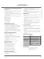
SYLLABUS
Overview:
Introduction: FAQs about Software Engineering; Professional and Ethical Responsibility;
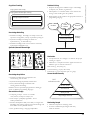
Software Process:
Models; Process Iteration, Specification, Software Design and
Implementation; Verification & Validation; Software Evolution; Automated Process Support.
Software Project Management and Requirements
Project Management: Management Activities, Project Pl Software Project Management and
Requirements Project Management: Management Activities, Project Planning, Project
Scheduling, Risk Management; Software Requirements: Functional and Non-Functional
Requirements, User Requirements, System Requirements, Requirements Document;
Requirements Engineering Process: Feasibility Studies, Requirements Elicitation and Analysis,
Requirements Validation, Requirements Management.
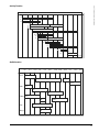
System Models, Software Prototyping and Specifications
System Models, Software Prototyping and Specifications System models: Context, Behavioural,
Data, and Object models, CASE Workbenches; Software Prototyping: Prototyping in the
Software Process, Rapid Prototyping Techniques, User Interface Prototyping; Specifications:
Formal Specification in the Software Process, Interface Specification, Behavioural Specification.
Architectural Design
Introduction: System Structuring; Control Models; Modular Decomposition; Domain- Specific
Architectures; Distributed Systems Architectures: Multiprocessor Architectures; Client-Server
Architectures, Distributed Object Architectures; CORBA (Common Object Request Broker
Architecture)
Software Design
Object Oriented Design: Objects and Object Classes, Object-Oriented Design Process, Design
Evolution; Real Time Software Design: Systems Design, Real-Time Executives, Monitoring and
Control Systems, Data Acquisition Systems; Design with Reuse: Component-Based
Development, Application Families, Design Patterns; User Interface Design: Principles, User
Interaction, Information Presentation, User Support, Interface Evaluation.
Verification, Validation and Testing
Verification and Validation (V & V): Static and Dynamic V & V, V & V Goals, V & V vs.
Debugging, Software Inspections / Reviews, Clean-Room Software Development; Software
Testing: Defect Testing, Integration Testing, Interface Testing, Object-Oriented Testing, Testing
Workbenches
Managing People
Introduction; Limits to Thinking; Memory Organization; Knowledge Modeling; Motivation;
Group Working; Choosing and Keeping People; the People Capability Maturity Model
Software Cost Estimation and Quality Management
Software Cost Estimation: Productivity, Estimation Techniques, Algorithmic Cost Modelling,
Project Duration and Staffing. Quality Management: Quality Assurance and Standards, Quality
Planning, Quality Control, Software Measurement and Metrics; Process Improvement: Process
and Product Quality, Process Analysis and Modelling, Process Measurement, the SEI Process
Maturity Model, and Process Classification
Evolution
Legacy Systems: Structures, Design, and Assessment; Software Change: Program Evolution
Dynamics, Software Maintenance, Architectural Evolution; Software Re- Engineering: Source
Code Translation, Reverse Engineering, Program Structure Improvement, Program
Modularization, Data Re-Engineering; Configuration Management
Suggested Readings:
1. Software Engineering: An Engineering Approach, by J.F.Peters and W. Pedrycz,
Publisher: John Wiley and Sons
2. Software Engineering: A Practitioner's Approach by Roger Pressman, Publisher:
McGraw-Hill
3. Fundamentals of Software Engineering by Ghezzi, Jayazeri, and Mandrioli, Publisher:
Prentice-Hall
4. Software Engineering Fundamentals by Ali Behforooz, and Frederick J.Hudson,
Publisher: Oxford University Press
SOFTWARE ENGINEERING
SOFTWARE ENGINEERING (MBA)
COURSE OVERVIEW
Software systems are now ubiquitous. Virtually all electrical equipment now includes some kind of
software; software is used to help run manufacturing industry, schools and universities, health care,
finance and government; many people use software of different kinds for entertainment and education.
The specification, development, management and evolution of these software systems make up the
discipline of software engineering.
Even simple software systems have a high inherent complexity so engineering principles have to be used
in their development. Software engineering is therefore an engineering discipline where software
engineers use methods and theory from computer science and apply this cost-effectively to solve difficult
problems. These difficult problems have meant that many software development projects have not
been successful. However, most modern software provides good service to its users; we should not let
high-profile failures obscure the real successes of software engineers over the past 30 years.
Software engineering was developed in response to the problems of building large, custom software
systems for defence, government and industrial applications. We now develop a much wider range of
software from games on specialized consoles through personal PC products and web-based systems to
very large-scale distributed systems. Although some techniques that are appropriate for custom systems,
such as object-oriented development, are universal, new software engineering techniques are evolving for
different types of software. It is not possible to cover everything in one book so I have concentrated on
universal techniques and techniques for developing large-scale systems rather than individual software
products.
Although the book is intended as a general introduction to software engineering, it is oriented towards
system requirements engineering. I think this is particularly important for software engineering in the
21st century where the challenge we face is to ensure that our software meets the real needs of its users
without causing damage to them or to the environment.
The approach that I take in this book is to present a broad perspective on software engineering and I
don’t concentrate on any specific methods or tools. There are no simple solutions to the problems of
software engineering and we need a wide spectrum of tools and techniques to solve software engineering problems.
i
SOFTWARE ENGINEERING
Software Engineering
CONTENT
Lesson No.
iv
Topic
Page No.
Lesson 1
Introduction
1
Lesson 2
Software Processes
6
Lesson 3
Software Processes
9
Lesson 4
Project Management
13
Lesson 5
Project Management
16
Lesson 6
Software Requirements
20
Lesson 7
Software Requirements
23
Lesson 8
Requirements Engineering Process
27
Lesson 9
Requirements Engineering Process
31
Lesson 10
System Models
36
Lesson 11
System Models
39
Lesson 12
Software Prototyping
43
Lesson 13
Software Prototyping
45
Lesson 14
Formal Specifications
49
Lesson 15
Architectural Design
54
Lesson 16
Architectural Design
57
Lesspn 17
Distributed Systems Architectures
61
Lesson 18
Distributed Systems Architectures
64
Lesson 19
Object-Oriented Design
67
Lesson 20
Object-Oriented Design
70
Lesson 21
Real-time Software Design
74
Lesson 22
Real-time Software Design
78
Lesson 23
Design with Reuse
81
Lesson 24
User Interface Design
85
Lesson 25
User Interface Design
88
Lesson 26
Verification and Validation
93
Lesson 27
Software Testing
97
Lesson 28
Software Testing
101
Lesson 29
Managing People
104
SOFTWARE ENGINEERING
Software Engineering
CONTENT
Lesson No.
8
9
Topic
Page No.
Lesson 30
Managing People
106
Lesson 31
Software Cost Estimation
112
Lesson 32
Software Cost Estimation
115
Lesson 33
Quality Management
120
Lesson 34
Quality Management
123
Lesson 35
Process Improvement
127
Lesson 36
Legacy Systems
132
Lesson 37
Software Change
139
Lesson 38
Software Re-Engineering
144
Lesson 39
Configuration Management
149
Lesson 40
Configuration Management
152
v
LESSON 1:
INTRODUCTION
UNIT I
OVERVIEW AND REQUIREMENTS
UNIT 1
CHAPTER 1
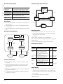
Software products may be developed for a particular customer
or may be developed for a general market
Objectives
Software products may be
•
To introduce software engineering and to explain its
importance
•
Generic - developed to be sold to a range of different
customers
•
To set out the answers to key questions about software
engineering
•
Bespoke (custom) - developed for a single customer
according to their specification
•
To introduce ethical and professional issues and to explain
why they are of concern to software engineers
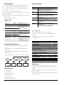
What is Software Engineering?
Software engineering is an engineering discipline, which is
concerned with all aspects of software production
Software engineers should adopt a systematic and organised
approach to their work and use appropriate tools and techniques depending on the problem to be solved, the
development constraints and the resources available
Topics Covered
•
FAQs about software engineering
•
Professional and ethical responsibility
Software Engineering
The economies of ALL developed nations are
dependent on software
More and more systems are software controlled
Software engineering is concerned with theories, methods and
tools for professional software development
Software engineering expenditure represents a
significant fraction of GNP in all developed countries
Software Costs
Software costs often dominate system costs. The costs of
software on a PC are often greater than the hardware cost
Software costs more to maintain than it does to develop. For
systems with a long life, maintenance costs may be several times
development costs
Software engineering is concerned with cost-effective software
development
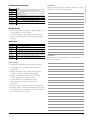
FAQs About Software Engineering
What is software?
What is software engineering?
What is the difference between software engineering and
computer science?
What is the difference between software engineering and system
engineering?
What is a software process?
What is a software process model?
What are the costs of software engineering?
What are software engineering methods?
What is CASE (Computer-Aided Software Engineering)
What are the attributes of good software?
What are the key challenges facing software engineering?
SOFTWARE ENGINEERING
Getting Started With Software
Engineering
What is The Difference Between Software
Engineering and Computer Science?
Computer science is concerned with theory and fundamentals;
software engineering is concerned with the practicalities of
developing and delivering useful software
Computer science theories are currently insufficient to act as a
complete underpinning for software engineering
What is The Difference Between Software
Engineering and System Engineering?
System engineering is concerned with all aspects of computerbased systems development including hardware, software and
process engineering. Software engineering is part of this process
System engineers are involved in system specification, architectural design, integration and deployment
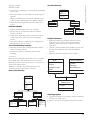
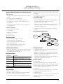
What is a Software Process?
A set of activities whose goal is the development or evolution
of software
Generic activities in all software processes are:
• Specification : what the system should do and its
development constraints
• Development : production of the software system
• Validation : checking that the software is what the customer
wants
• Evolution : changing the software in response to changing
demands
What is a Software Process Model?
A simplified representation of a software process, presented
from a specific perspective
Examples of process perspectives are
• Workflow perspective : sequence of activities
What is Software?
Computer programs and associated documentation
1
SOFTWARE ENGINEERING
•
Data-flow perspective : information flow
Software must be usable by the users for which it was designed
•
Role/action perspective : who does what
What are the Key Challenges Facing Software
Engineering?
Coping with legacy systems, coping with increasing diversity and
coping with demands for reduced delivery times
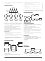
Generic Process Models
•
Waterfall
•
Evolutionary development
•
Formal transformation
•
Integration from reusable components
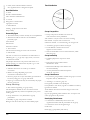
What are The Costs of Software Engineering?
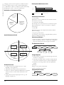
Roughly 60% of costs are development costs, 40% are testing
costs. For custom software, evolution costs often exceed
development costs
Costs vary depending on the type of system being developed
and the requirements of system attributes such as performance
and system reliability
Distribution of costs depends on the development model that
is used
What are Software Engineering Methods?
Structured approaches to software development which include
system models, notations, rules, design advice and process
guidance
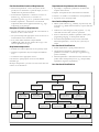
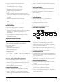
Model Descriptions
Legacy Systems
Old, valuable systems must be maintained and updated
Heterogeneity
Systems are distributed and include a mix of hardware and
software
Delivery
There is increasing pressure for faster delivery of software
Professional and Ethical Responsibility
Software engineering involves wider responsibilities than simply
the application of technical skills
Software engineers must behave in an honest and ethically
responsible way if they are to be respected as professionals
Ethical behaviour is more than simply upholding the law.
Issues of Professional Responsibility
Confidentiality
Rules
Engineers should normally respect the confidentiality of their
employers or clients irrespective of whether or not a formal
confidentiality agreement has been signed.
Constraints applied to system models
Competence
Recommendations
Engineers should not misrepresent their level of competence.
They should not knowingly accept work, which is out with,
their competence.
Descriptions of graphical models, which should be produced
Advice on good design practice
Process Guidance
What activities to follow
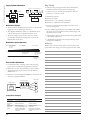
What is Case (Computer-aided Software
Engineering)?
Software systems which are intended to provide automated
support for software process activities. CASE systems are often
used for method support
Intellectual Property Rights
Engineers should be aware of local laws governing the use of
intellectual property such as patents, copyright, etc. They should
be careful to ensure that the intellectual property of employers
and clients is protected.
Computer Misuse
Tools to support the early process activities of requirements and
design
Software engineers should not use their technical skills to
misuse other people’s computers. Computer misuse ranges
from relatively trivial (game playing on an employer’s machine,
say) to extremely serious (dissemination of viruses).
Lower-CASE
ACM/IEEE Code of Ethics
Upper-CASE
Tools to support later activities such as programming, debugging and testing
What are The Attributes of Good Software?
The software should deliver the required functionality and
performance to the user and should be maintainable, dependable and usable
Maintainability
Software must evolve to meet changing needs
Dependability
The professional societies in the US have cooperated to produce
a code of ethical practice.
Members of these organisations sign up to the code of practice
when they join.
The Code contains eight Principles related to the behaviour of
and decisions made by professional software engineers,
including practitioners, educators, managers, supervisors and
policy makers, as well as trainees and students of the profession.
Software must be trustworthy
Code of Ethics : Preamble
Efficiency
Preamble
• The short version of the code summarizes aspirations at a
high level of the abstraction; the clauses that are included in
Software should not make wasteful use of system resources
Usability
2
•
Software engineers shall commit themselves to making the
analysis, specification, design, development, testing and
maintenance of software a beneficial and respected
profession. In accordance with their commitment to the
health, safety and welfare of the public, software engineers
shall adhere to the following Eight Principles:
Code of Ethics : Principles
1. Public
Software engineers shall act consistently with the public interest.
2. Clients and Employer
Software engineers shall act in a manner that is in the best
interests of their client and employer consistent with the public
interest.
3. Product
Software engineers shall ensure that their products and related
modifications meet the highest professional standards possible.
The software process consists of activities, which are involved,
in developing software products. Basic activities are software
specification, development, validation and evolution.
Methods are organised ways of producing software. They
include suggestions for the process to be followed, the
notations to be used, and rules governing the system descriptions, which are produced and design guidelines.
CASE tools are software systems, which are designed to
support routine activities in the software process such as editing
design diagrams, checking diagram consistency and keeping track
of program tests which have been run.
Software engineers have responsibilities to the engineering
profession and society. They should not simply be concerned
with technical issues.
Professional societies publish codes of conduct, which set out
the standards of behaviour expected of their members.
Activity
What are the four important attributes, which all software
products have? Suggest four attributes, which may be
significant.
4. Judgment
Software engineers shall maintain integrity and independence in
their professional judgment.
5. Management
Software engineering managers and leaders shall subscribe to
and promote an ethical approach to the management of
software development and maintenance.
6. Profession
Software engineers shall advance the integrity and reputation of
the profession consistent with the public interest.
7. Colleagues
Software engineers shall be fair to and supportive of their
colleagues.
8. Self
Software engineers shall participate in lifelong learning regarding
the practice of their profession and shall promote an ethical
approach to the practice of the profession.
Ethical Dilemmas
Disagreement in principle with the policies of senior management
Your employer acts in an unethical way and releases a safetycritical system without finishing the testing of the system
Participation in the development of military weapons systems
or nuclear systems
Key Points
Software engineering is an engineering discipline, which is
concerned with all aspects of software production.
Software products consist of developed programs and associated documentation. Essential product attributes are
maintainability, dependability, efficiency and usability.
3
SOFTWARE ENGINEERING
the full version give examples and details of how these
aspirations change the way we act as software engineering
professionals. Without the aspirations, the details can
become legalistic and tedious; without the details, the
aspirations can become high sounding but empty; together,
the aspirations and the details form a cohesive code.
SOFTWARE ENGINEERING
Activity
Activity
What are the four important attributes, which all software
products should have? Suggest four other attributes, which
may be significant.
Software engineering methods only became widely used when
CASE technology became available to support them. Suggest
five types of method support, which can be provided by CASE
tools.
Activity
Activity
Explain why system-testing costs are particularly high for generic
software products, which are sold to a very wide market.
Apart from the challenges of legacy systems, heterogeneity and
rapid delivery, identify other problems and challenges that
software engineering is likely to face in the 21st century.
4
SOFTWARE ENGINEERING
Notes -
5
UNIT I
OVERVIEW AND REQUIREMENTS
LESSON 2 AND 3:
SOFTWARE PROCESSES
SOFTWARE ENGINEERING
Coherent Sets of Activities For Specifying, Designing,
Implementing And Testing Software Systems
CHAPTER 2
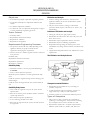
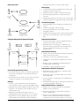
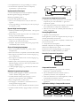
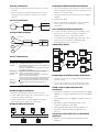
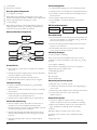
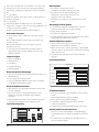
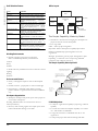
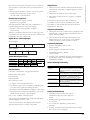
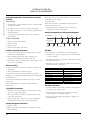
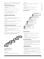
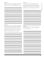
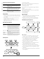
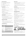
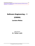
Waterfall Model
Objectives
•
To introduce software process models
•
To describe a number of generic process models and when
they may be used
•
To outline lower-level process models for requirements
engineering, software development, testing, and evolution
•
To introduce CASE technology to support software process
activities
Requirements
definition
System and
software design
Implementation
and unit testing
Integration and
system testing
Topics Covered
•
Software process models
•
Process iteration
•
Software specification
•
Software design and implementation
•
Software verification & validation
•
Software evolution
Automated process support
The Software Process
A structured set of activities required to develop a
software system
•
Specification
•
Design
•
Validation / verification
•
Evolution
A software process model is an abstract representation of a
process. It presents a description of a process from some
particular perspective
Models should be as simple as possible, but no
Simpler. – A. Einstein
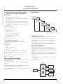
Generic Software Process Models
The Waterfall Model : separate and distinct phases of specification and development
Evolutionary Development : specification and development are
interleaved
Formal Systems Development : a mathematical system model is
formally transformed to an implementation
Reuse-Based Development : the system is assembled from
existing components
6
Operation and
maintenance
Waterfall Model Problems
Inflexible partitioning of the project into distinct stages makes
it difficult to respond to changing customer requirements.
Thus, this model is only appropriate when the requirements are
well understood.
In general, the drawback of the waterfall model is the difficulty
of accommodating change after the process is underway.
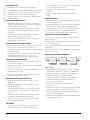
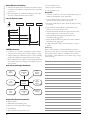
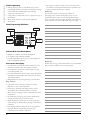
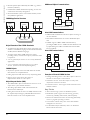
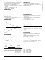
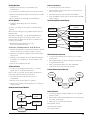
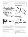
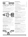
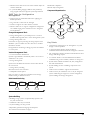
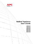
Evolutionary Development
Exploratory Development *– objective is to work with
customers and to evolve a final system from an initial outline
specification. (Development starts with well-understood parts
of system.)
Throwaway Prototyping – objective is to understand the system
requirements. (Prototyping focuses on poorly understood
requirements.)
• Also known as exploratory programming, or evolutionary
prototyping
Evolutionary development
Concurrent
activities
Outline
description
Specification
Initial
version
Development
Intermediate
versions
Validation
Final
version
•
Process stages
•
Lack of process visibility
•
Reusable software analysis
•
Final version/prototype is often poorly structured
•
Requirements modification
•
Special skills (e.g., in languages for rapid prototyping) may be
required
•
System design with reuse
•
Development and integration
Applicability
• For small or medium-size interactive systems
• For parts of large systems (e.g., the user interface)
• For short-lifetime systems (in case of exploratory
development)
This approach is becoming more important, but experience is
still limited.
R e qu ire m e n ts
s pe c ifi c a ti on
Integration and
system testing
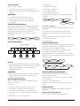
Formal
transformation
Formal
specification
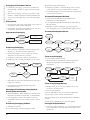
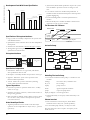
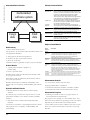
Formal Transformations
Formal transformations
T1
Formal
specification
T2
R1
P1
T3
R2
P2
T4
Executable
program
R3
P3
C o m po ne nt
a na l ys is
R e qu ire m e n ts
m o di fi c a ti on
S yst e m de sig n
w i th re u se
D e ve l opm e nt
a nd int e gr a tio n
Formal Systems Development
Based on the transformation of a mathematical specification
through different representations to an executable program
Transformations are “correctness-preserving” so it is possible to
show that the program conforms to its specification
Embodied in Mills’ “Clean room” approach to software
development
Requirements
definition
SOFTWARE ENGINEERING
Potential Problems
P4
S y st e m
v al id a ti on
Process Iteration
For large systems, requirements ALWAYS evolve in the course
of a project.
Thus, process iteration is ALWAYS part of the process.
Iteration can be incorporated in any of the generic process
models
Two other approaches that explicitly incorporate iteration:
•
Incremental development
•
Spiral development
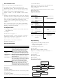
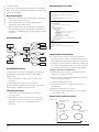
Incremental Development
Rather than deliver the system as a single unit, the development
and delivery is broken down into increments, each of which
incorporates part of the required functionality.
User requirements are prioritised and the highest priority
requirements are included in early increments.
Once the development of an increment is started, its requirements are “frozen” while requirements for later increments can
continue to evolve.
Proofs of transformation correctness
Define outline
requirements
Assign requirements
to increments
Design system
architecture
Problems
•
Need for specialized skills and training to apply the technique
•
Difficult to formally specify some aspects of the system such
as the user interface (thus, focus is usually limited to
functional requirements)
Applicability
• Critical systems, especially those where a safety or security case
must be made before the system is put into operation
•
Critical parts of large systems
Reuse-oriented Development
Based on systematic (as opposed to serendipitous) reuse of
existing software units
Units may be:
• Procedures or functions (common for past 40 years)
• Components (“component-based development”)
• Core elements of an application (“application family”)
• Entire applications — COTS (Commercial-off-the-shelf)
systems
May also be based on use of design patterns
Develop system
increment
Validate
increment
Integrate
increment
Validate
system
Final
system
System incomplete
Incremental Development Advantages
Useful functionality is delivered with each increment, so
customers derive value early.
Early increments act as a prototype to help elicit requirements
for later increments.
Lower risk of overall project failure
The highest priority system services tend to receive the most
testing.
Potential Problem
Requirements may NOT be partitionable into stand-alone
increments.
Extreme Programming (Beck ’99)
Recent evolution of incremental approach based on
7
SOFTWARE ENGINEERING
•
Development and delivery of very small increments of
functionality
•
Significant customer involvement in process
•
Constant code improvement
•
Ego less, pair-wise programming
Requirements Engineering Process
• Feasibility (technical and otherwise) study
• Requirements elicitation and analysis
• Requirements specification (documentation)
• Requirements validation
NOT document-oriented
Gaining acceptance in some small organizations
Representative of the “agile” development paradigm
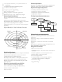
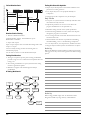
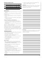
Boehm’s Spiral Development
Process is represented as a spiral rather than a sequence of
activities.
Each loop in the spiral represents a phase in the process.
No fixed phases such as specification or design — loops in the
spiral are chosen depending on what is required
Explicitly incorporates risk assessment and resolution throughout
the process
Spiral Model of the Software Process
Determine objectives
alternatives and
constraints
Risk
analysis
Evaluate alternatives
identify, resolve risks
Risk
analysis
Risk
analysis
REVIEW
Requirements plan
Life-cycle plan
Development
plan
Plan next phase
Integration
and test plan
Prototype 3
Prototype 2
Risk
analysis Prototype 1
Concept of
Operation
Operational
protoype
Simulations, models, benchmarks
S/W
requirements
Requirement
validation
Product
design
Detailed
design
Code
Unit test
Integration
test
Acceptance
test
Develop, verify
Service
next-level product
Design
V&V
Spiral Model Quadrants
Objective Setting : specific objectives for the phase are identified
Risk Assessment and Reduction : risks are assessed and
activities put in place to reduce the key risks
Development and Validation : a development model for the
system is chosen which can be any of the generic models
Planning : the project is reviewed and the next phase of the
spiral is planned
Models for Fundamental Process Activities
Software specification/requirements engineering
Software development (design and implementation)
Software verification and validation
Software evolution
8
Software Specification
The process of establishing what services are required and the
constraints on the system’s operation and development
The Requirements Engineering Process
Feasibility
study
Requirements
elicitation and
analysis
Requirements
specification
Feasibility
report
Requirements
validation
System
models
User and system
requirements
Requirements
document
Software Design and Implementation
The process of producing an executable system based on the
specification
Software design – design a software structure that realizes the
specification
Implementation – translate this structure into an executable
program
The activities of specification, design, and implementation are
closely related and may be inter-leaved.
Design Process Activities
“High-Level” design activities
• Architectural design : subsystems and their relationships are
identified
• Abstract specification : of each sub-system’s services
• Interface design : among sub-systems
“Low-Level” design activities
• Component design : services allocated to different
components and their interfaces are designed
• Data structure design
• Algorithm design
SOFTWARE ENGINEERING
The Software Design Process
Requirements
specification
Design activities
Architectural
design
Abstract
specification
Interface
design
Component
design
Data
structure
design
Algorithm
design
System
architecture
Software
specification
Interface
specification
Component
specification
Data
structure
specification
Algorithm
specification
Design products
Design Methods
Systematic (canned) approaches to developing a software design
The design is usually documented as a set of graphical models
Sub-system/product testing : sub-systems or products are
tested
Possible Models
System testing : testing of the system as a whole, including user
acceptance test
•
Data-flow model
•
Entity-relation-attribute model
•
Structural model
•
Object models
Programming and Debugging
Translating a design into a program and removing errors from
that program (compare with Clean room SE)
Programming is a “personal activity” - a there is no generic
programming process
(product/sub-system) Integration testing
Software Evolution
Software is inherently flexible and subject to change.
As requirements change through changing business circumstances, the software that supports the business must also
evolve and change.
The distinction between development and evolution is
increasingly irrelevant as fewer and fewer systems are completely
new.
Programmers carry out some program testing to discover faults
(“unit testing”), and remove faults in the debugging process
Define system
requirements
The Debugging Process
Locate
error
Design
error repair
Repair
error
Re-test
program
Software Verification & Validation
Verification and validation (V&V) determines whether or not a
system
(1) conforms to its specification and (2) meets the needs of the
customer.
Assess existing
systems
Propose system
changes
Modify
systems
Existing
systems
New
system
Automated Process Support (Case)
Computer-aided software engineering (CASE) is software to
support software development and evolution processes
Activity automation
Involves inspection / review processes and (machine-based)
testing
•
Graphical editors for system model development
Testing involves executing system elements with test cases that
are derived from specifications and/or program logic.
•
Data dictionaries for name management
•
GUI builders for user interface construction
•
Debuggers to support program faultfinding
•
Automated translators to generate new versions of a
program
Testing Stages
Unit/Module testing : individual function/procedures are
tested
(unit/module) Integration testing
Component testing : functionally related units/modules are
tested together
(component) Integration testing
(e.g., restructuring tools)
CASE Technology
CASE technology has led to significant improvements in the
software process, but not the order of magnitude improvements that were once predicted.
9
SOFTWARE ENGINEERING
•
Software engineering involves design activity requiring
creative thought : this is not readily automatable
•
Software engineering is a team activity and, for large projects,
much time is spent in team interactions. CASE technology
does not support this well.
CASE Classification
Classification helps us understand the different types of CASE
tools / systems and their support for process activities
Functional perspective : tools are classified according to their
specific function
Process perspective : tools are classified according to process
activities that are supported
Integration perspective : CASE systems are classified according
to their breadth of support for the software process
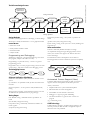
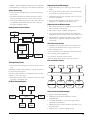
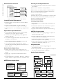
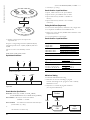
CASE Integration
Tools – support individual process tasks such as design
consistency checking, text editing, etc.
Workbenches : support a process phase such as specification or
design, Normally include a number of integrated tools
Environments : support all or a substantial part of an entire
software process. Normally include several integrated workbenches
Tools, Workbenches, Environments
CASE
technology
Tools
Editors
Workbenches
Compilers
File
comparators
Analysis and
design
Multi-method
workbenches
Integrated
environments
Programming
Single-method
workbenches
Environments
Process-centred
environments
Testing
General-purpose
workbenches
Language-specific
workbenches
Key Points
Software processes are the activities involved in producing and
evolving a software system. They are represented in a software
process model.
Fundamental activities are specification, design and implementation, validation & verification, and evolution.
Generic models are very general process models representing
different approaches to development.
Iterative process models describe the software process as a cycle
of activities.
10
Requirements engineering is the process of establishing what
services are required and the constraints on the system’s
operation and development.
Design and implementation processes produce an executable
system based on the specification.
V&V involves checking that the system meets its specification
and satisfies user needs.
Evolution is concerned with modifying the system after it is
placed in use.
CASE technology supports software process activities
Activity
Giving reasons for your answer based on the type of system
being developed, suggest the most appropriate generic software
process model which might be used as a basis for managing the
development of the following systems:
•
A system to control anti –lock braking in a car.
•
A virtual reality system to support software maintenance:
•
A university accounting system that replaces an existing
system;
•
An interactive system for railway passengers that finds train
times from terminals installed in stations.
Activity
Explain why programs which are developed using evolutionary
development are likely to be difficult to maintain.
Suggest why it is important to make a distinction between
developing the user requirements and developing the system
requirements in the requirements engineering process.
Activity
Activity
Explain how both the waterfall model of the software process
and the prototyping model can be accommodated in the spiral
process model.
Describe the main activities in the software design process and
the outputs of these activities. Using an entity- relation
diagram, show possible relationships between the outputs of
these activities.
SOFTWARE ENGINEERING
Activity
11
SOFTWARE ENGINEERING
Activity
Activity
What are the five components of a design method? Take any
method which you know and describe its components. Assess
the completeness of the method, which you have chosen.
Explain why a software system that is used in a real-world
environment must change or become progressively less useful.
Activity
Activity
Design a process model for running system tests and recording
their results.
Suggest how a CASE technology classification scheme may be
helpful to managers responsible for CASE system procurement.
12
UNIT I
OVERVIEW AND REQUIREMENTS
LESSON 4 AND 5:
PROJECT MANAGEMENT
•
Many techniques of engineering project
management are equally applicable to software project
management.
•
Technically complex engineering systems tend to suffer from
most of the same problems as software systems.
Objectives
•
To introduce software project management and to describe
its distinctive characteristics
•
To discuss project planning and the planning process
•
To show how graphical schedule representations are used by
project management
•
To discuss the notion of risks and the risk management
process
Topics Covered
•
Management activities
•
Project planning
•
Project scheduling
•
Risk management
Software Project Management
• Concerned with activities involved in ensuring
that software is delivered on time, within budget and in
accordance with the requirements of the organizations
developing and procuring the software.
• Project management is needed because software
development is always subject to budget and schedule
constraints that are set by the organization developing the
software.
Software Management Distinctions
• The product is intangible.
• The product is uniquely flexible.
• Software engineering is not recognized as an engineering
discipline with the same status as mechanical, electrical
engineering, etc.
• The software development process is not
standardized.
• Many software projects are “one-off ” projects.
Management Activities
• Proposal writing (to fund new projects)
• Project planning and scheduling
• Project costing and preparing bids
• Project monitoring and reviews
• Personnel selection and evaluation
• Report writing and presentations
• Attending lots and lots of meetings!
Project Staffing
• May not be possible to appoint the ideal people to work on
a project…
•Project budget may not allow for use of highly paid staff.
•Those with appropriate skills / experience may not be
available.
•An organization may wish to develop employee skills by
assigning inexperienced staff.
• Managers have to work within these constraints especially
when (as is currently the case) there is an international
shortage of skilled IT staff.
Project Planning
•
Probably the most time-consuming project management
activity (or at least it should be).
•
Continuous activity from initial concept to system delivery.
Plans must be regularly revised as new information becomes
available.
•
Different types of sub-plans may be developed to support a
main software project plan concerned with overall schedule
and budget.
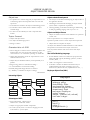
Types of Project Sub-plans
Plan
Quality plan
Validation plan
Configuration
management plan
Maintenance plan
Staff development plan.
Description
Describes the quality
procedures and
standards that will be used in a project.
Describes the approach, resources and
schedule used for system validation.
Describes the configuration management
procedures and structures to be used.
Predicts the maintenance requirements of
the system, maintenance costs and
effort
required.
Describes how the skills and experience of
the project team
members will be
developed.
Project Planning
• “The plan is nothing – the planning is everything.”
– Dwight Eisenhower, on the
D-Day invasion plan
Management Commonalities
• These activities are not peculiar to software
management.
13
SOFTWARE ENGINEERING
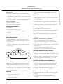
Organizing, Planning and Scheduling Software Projects
UNIT 2
CHAPTER 3
SOFTWARE ENGINEERING
Project Planning Process
Establish the project constraints
Make initial assessments of the project parameters
Define project milestones and deliverables
while project has not been completed or canceled loop
Draw up project schedule
Initiate activities according to schedule
Wait (for a while)
Revise estimates of project schedule
Re-negotiate project constraints and deliverables
if (problems arise) then
Initiate technical review and possible revision
end if
end loop
Project Plan Document Structure
• Introduction (goals, constraints, etc.)
• Project organisation
• Risk analysis
• Hardware and software resource requirements
• Work breakdown
• Project schedule
• Monitoring and reporting mechanisms
Activity Organization
• Activities in a project should be associated with tangible
outputs for management to judge progress (i.e., to provide
process visibility)
• Milestones are the unequivocal end-points of process
activities.
• Deliverables are project results delivered to customers.
(There are also internal deliverables.)
• The waterfall model allows for the straightforward definition
of milestones (“a deliverable oriented model”).
• Deliverables are always milestones, but milestones are not
necessarily deliverables
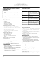
Milestones in The Re Process
ACTIVITIES
Feasibility
study
Requirements
analysis
Prototype
development
Design
study
Requirements
specification
Feasibility
report
Requirements
definition
Evaluation
report
Architectural
design
Requirements
specification
•
Organize as concurrent activities to make optimal use of
workforce.
•
Minimize task dependencies to avoid potential delays.
•
Dependent on project managers’ intuition and experience
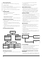
The Project Scheduling Process
Identify
activities
Identify activity
dependencies
Estimate resources
for activities
Software
requirements
Activity charts
and bar charts
Scheduling Problems
• Estimating the difficulty of problems, and hence the cost of
developing solutions, is hard.
• Progress is generally not proportional to the number of
people working on a task.
• Adding people to a late project can make it later. (due to
coordination overhead)
• The unexpected always happens. Always allow for different
contingencies in planning.
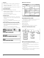
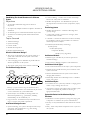
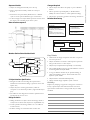
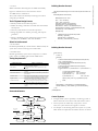
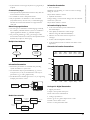
Bar Charts and Activity Networks
• Graphical notations are often used to illustrate project
schedules.
• Activity charts (a.k.a. PERT* charts) show task dependencies,
durations, and the critical path.
• Bar charts (a.k.a. GANTT charts) generally show resource
(e.g., people) assignments and calendar time.
* Program Evaluation and Review Technique
Task Durations and Dependencies
Task
T1
T2
T3
T4
T5
T6
T7
T8
T9
T10
T11
T12
Duration (days)
8
15
15
10
10
5
20
25
15
15
7
10
M1
8 day s
•
Tasks should not be too small or too large they should last
on the order of weeks for projects lasting months.
T2, T4 (M2)
T1, T2 (M3)
T1 (M1)
T4 (M5)
T3, T6 (M4)
T5, T7 (M7)
T9 (M6)
T11 (M8)
2 5/ 7/99
4/7/99
s tart
1 5 d ay s
T3
T9
T1
Split project into tasks and estimate time and resources
required to complete each.
T1 (M1)
1 5 d ay s
1 4/ 7/99
•
Dependencies
Activity Network
MILESTONES
Project Scheduling
Create project
charts
Allocate people
toactivities
5 d ays
4/ 8/99
2 5/8/99
T6
M4
M6
M3
7 day s
2 0 d ay s
1 5 d ay s
T7
T2
2 5/7/99
1 0 d ay s
M2
T4
T1 1
1 0 d ay s
5/9/99
1 1/ 8/99
M7
T5
T10
1 8/ 7/99
M8
1 5 d ay s
10 days
T12
M5
2 5 d ay s
T8
Fi nish
1 9/9/ 99
14
4/7
11/7
18/7
25/7
1/8
8/8
15/8
22/8
29/8
5/9
12/9
SOFTWARE ENGINEERING
Activity Timeline
19/9
Start
T4
T1
T2
M1
T7
T3
M5
T8
M3
M2
T6
T5
M4
T9
M7
T10
M6
T1 1
M8
T12
Finish
Staff Allocation
4/7
Fred
11/7 18/7 25/
1/8
8/8
15/8 22/8 29/8 5/9
12/9 19/9
T4
T8
T11
T12
Jane
T1
T3
T9
Anne T2
T6
Jim
Mary
T10
T7
T5
15
SOFTWARE ENGINEERING
Risk Management
• Risk management is concerned with identifying risks and
drawing up plans to minimize their effect on a project.
• A risk is a probability that some adverse circumstance will
occur.
Project risks affect schedule or resources.
Product risks affect the quality or performance of the software
being developed.
Business risks affect the organisation developing or procuring
the software.
(Taxonomy based on Effect)
Software Risks
Risk t ype
Project
Mana gement change
Project
Hardw are unavailab ility
Project
Requirements change
Project and
product
Specification delays
Project and
product
Project and
product
Product
CAS E t ool underperformance
Tec hnology change
Product comp etition
Bus iness
Bus iness
Description
Experienced staff will leave the
projec t befor e it is finis hed.
There will be a c hange of
organ isational management with
different priorities.
Hardw are which is ess ential for the
projec t w ill not be delivered on
sched ule.
There will be a larger numb er of
changes to the requirements than
anticipate d.
Specifications of ess ential interfaces
are not available on sc hedule
The size of the syst em has been
underestimated.
CASE t ools w hich su pport the
projec t do not perform as anticipated
The underlying technology on which
the sys tem is b ui lt is su pe rseded by
new tec hnology.
A competitive product is marketed
before t he sys tem is com plete d.
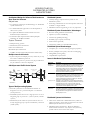
The Risk Management Process
• Risk identification : identify project, product and business
risks
• Risk analysis : assess the likelihood and consequences of
these risks
• Risk planning : draw up plans to avoid or minimise the
effects of the risk
• Risk monitoring : monitor the risks throughout the project
Risk
identification
Risk analysis
Riskplanning
Risk
monitoring
List of potential
risks
Prioritisedrisk
list
Risk avoidance
and contingency
plans
Risk
assessment
Risk Identification
• Technology risks
• People risks
• Organisational risks
• Requirements risks
• Estimation risks
(Taxonomy based on Source)
16
Risk type
Technology
People
Organisational
Tools
Requirements
Risk
Staff turnover
Size underestimate
Risks and Risk Types
Estimation
Possible risks
The database used in the system cannot process as
many transactions per second as expected.
Software components which should be reused contain
defects which limit their functionality.
It is impossible to recruit staff with the skills required.
Key staff are ill and unavailable at critical times.
Required training for staff is not available.
The organisation is restructured so that different
management are responsible for the project.
Organisational financial problems force reductions in the
project budget.
The code generated by CASE tools is inefficient.
CASE tools cannot be integrated.
Changes to requirements which require major design
rework are proposed.
Customers fail to understand the impact of requirements
changes.
The time required to develop the software is
underestimated.
The rate of defect repair is underestimated.
The size of the software is underestimated.
Risk Analysis
•
Assess probability and seriousness of each risk.
•
Probability may be very low, low, moderate, high or very
high.
•
Risk effects might be catastrophic, serious, tolerable or
insignificant.
Risk
Organisational financial problems force reductions
in the project budget.
It is impossible to recruit staff with the skills
required for the project.
Key staff are ill at critical times in the project.
Software components which should be reused
contain defects which limit their functionality.
Changes to requirements which require major
design rework are proposed.
The organisation is restructured so that different
management are responsible for the project.
The database used in the system cannot process
as many transactions per second as expected.
The time required to develop the software is
underestimated.
CASE tools cannot be integrated.
Customers fail to understand the impact of
requirements changes.
Required training for staff is not available.
The rate of defect repair is underestimated.
The size of the software is underestimated.
The code generated by CASE tools is inefficient.
Probability Effects
Low
Catastrophic
High
Catastrophic
Moderate
Moderate
Serious
Serious
Moderate
Serious
High
Serious
Moderate
Serious
High
Serious
High
Moderate
Tolerable
Tolerable
Moderate
Moderate
High
Moderate
Tolerable
Tolerable
Tolerable
Insignificant
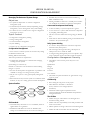
Risk Planning
Consider each risk and develop a strategy to manage that risk.
Avoidance strategies : the probability that the risk will arise is
reduced.
Minimisation strategies : the impact of the risk on the project or
product is reduced.
Contingency plans : if the risk arises, contingency plans are plans
to deal with that risk.
Risk
Organisational
financial problems
Recruitment
problems
Staff illness
Defective
components
Requirements
changes
Organisational
restructuring
Database
performance
Underestimated
development time
Strategy
Prepare a briefing document for senior management showing how the project is
making a very important contribution to the goals of the business.
Alert customer of potential difficulties and the possibility of delays, investigate
buying-in components.
Reorganise team so that there is more overlap of work and people therefore
understand each other’s jobs.
Replace potentially defective components with bought-in components of known
reliability.
Derive traceability information to assess requirements change impact, maximise
information hiding in the design.
Prepare a briefing document for senior management showing how the project is
making a very important contribution to the goals of the business.
Investigate the possibility of buying a higher-performance database.
Activitiy
Explain why the intangibility of software systems poses special
problems for software project management.
Investigate buying in components, investigate use of a program generator.
Risk Monitoring
• Assess each identified risk regularly to decide whether or not
it is becoming less or more probable.
• Also assess whether the effects of the risk have changed.
• Each key risk should be discussed at management progress
meetings.
Risk Factors
Risk
Organisational
financial problems
Recruitment
problems
Staff illness
Defective
components
Requirements
changes
Organisational
restructuring
Database
performance
Underestimated
development time
Strategy
Prepare a briefing document for senior management showing how the project is
making a very important contribution to the goals of the business.
Alert customer of potential difficulties and the possibility of delays, investigate
buying-in components.
Reorganise team so that there is more overlap of work and people therefore
understand each other’s jobs.
Replace potentially defective components with bought-in components of known
reliability.
Derive traceability information to assess requirements change impact, maximise
information hiding in the design.
Prepare a briefing document for senior management showing how the project is
making a very important contribution to the goals of the business.
Investigate the possibility of buying a higher-performance database.
Investigate buying in components, investigate use of a program generator.
Activitiy
Explain why the best programmers do not always make the
best software managers.
Key Points
•
Good project management is essential for project success.
•
The intangible nature of software causes problems for
management.
•
Managers have diverse roles, but their most significant
activities are planning, estimating, and scheduling.
•
Planning and estimating are iterative processes, which
continue throughout the course of a project.
•
A project milestone is a predictable state where
some formal report of progress is presented to
management.
•
Risks may be project risks, product risks or business risks.
•
Risk management is concerned with identifying risks, which
may affect the project, and planning to ensure that these risks
do not develop into major threats.
17
SOFTWARE ENGINEERING
Risk Management Strategies
SOFTWARE ENGINEERING
Activity
Explain why the process of project planning is an iterative one
and why a plan; must be continually reviewed during a software
project.
Activity
What is the critical distinction between a milestone and a
deliverable?
Activity
Following figure sets out a number of activities, durations and
dependencies. Draw an activity chart and a bar chart showing the
project schedule.
Activity
Briefly explain the purpose of each of the sections in a software
project plan.
18
Task
T1
T2
T3
T4
T5
T6
T7
T8
T9
T10
T11
T12
T13
T14
T15
T16
Duration
10
15
10
20
10
15
20
35
15
5
10
20
35
10
20
10
Dependencies
T1
T1, T2
T3, T4
T3
T7
T6
T5, T9
T9
T10
T3, T4
T8, T9
T12, T14
T15
Notes:
SOFTWARE ENGINEERING
Activity
You are asked by your manager to deliver software to a schedule, which you know can only be met, by asking your project
team to work unpaid overtime. All team members have young
children. Discuss whether you should accept this demand form
your manager or whether you should persuade your team to
give their time to the organization rather than their families.
What factors might be significant in your decision?
Activity
As a programmer, you are offered promotion to project
management but you feel that you can make a more effective
contribution in a technical rather than a managerial role. Discuss
whether you should accept the promotion.
19
UNIT I
OVERVIEW AND REQUIREMENTS
LESSON 6 AND 7:
SOFTWARE REQUIREMENTS
SOFTWARE ENGINEERING
Objectives
•
To introduce the concepts of abstract “user” and more
detailed “system” requirements
•
To describe functional and non-functional requirements
•
To explain two techniques for describing system
requirements: structured NL and PDLs
•
To suggest how software requirements may be organized in
a requirements document
May be the basis for the contract itself — must be defined in
detail
May be the basis for design and implementation – must bridge
requirements engineering and design activities
•
User requirements : statements in natural language plus
diagrams of system services and constraints. Written
primarily for customers.
•
System requirements : structured document setting out
detailed descriptions of services and constraints precisely.
May serve as a contract between client and developer.
•
Software design specification : implementation oriented
abstract description of software design, which may utilize
formal (mathematical) notations. Written for developers.
Topics Covered
•
Functional and non-functional requirements
•
User requirements
•
System requirements
•
The software requirements document
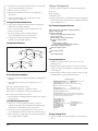
Requirements Engineering
•
•
The process of eliciting, analysing, documenting, and
validating the services required of a system and the
constraints under which it will operate and be developed.
Descriptions of these services and constraints are the
requirements for the system.
•
Requirements may be high-level and abstract, or detailed and
mathematical
•
The hardest single part of building a software system is
deciding precisely what to build. No other part of the
conceptual work is as difficult… No other part of the work
so cripples the resulting system if done wrong. No other
part is more difficult to rectify later.
– Fred Brooks, “No Silver Bullet…”
Why is Requirements Engineering So Hard?
• Difficulty of anticipation
• Unknown or conflicting requirements / priorities
• Conflicts between users and procurers
• Fragmented nature of requirements
• Complexity / number of distinct requirements
• Some analogies:
Working a dynamically changing jigsaw puzzle
Blind men describing an elephant
Different medical specialists describing an ill patient
Types of Requirements
• Requirements range from being high-level and abstract to
detailed and mathematical.
• This is inevitable as requirements may serve multiple uses.
May be the basis for a bid for a contract – must be open to
interpretation
20
CHAPTER 4
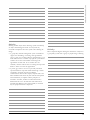
User and System Requirements
1. The software must provice a means of representing and
accessing external files created by other tools.
1. The user should be provided with facilities to define the
type of external files.
2. Each external file type may have an associated tool which
may be applied to the file.
3. Each external file type may be represented as a specific
icon on the user’s display.
4. Facilities should be provided for the icon representing an
external file type to be defined by the user.
5. When a user selects an icon representing an external file
the effect of that selection is to apply the tool associated
with the type of the external file to the file represented by
the selected icon.
Requirements Readers
User requirements
Client managers
System end-users
Client engineers
Contractor managers
System architects
System requirements
System end-users
Client engineers
System architects
Software developers
Examples of Functional Requirements
• The user shall be able to search either all of the initial set of
databases or select a subset from it.
• The system shall provide appropriate viewers for the user to
read documents in the document store.
• Every order shall be allocated a unique identifier
(ORDER_ID), which the user shall be able to copy to the
account’s permanent storage area
Requirements Imprecision
• Problems arise when requirements are not precisely stated.
• Ambiguous requirements may be interpreted in different
ways.
• Consider the term “appropriate viewers”
User intention : special purpose viewer for each different
document type
Developer interpretation : provide a text viewer that shows the
contents of the documents
Requirements Completeness and Consistency
• In principle, a requirements specification should be both
complete and consistent.
Complete : all required services and constraints are defined.
Consistent : no conflicts or contradictions in the requirements.
• In practice, this is nearly impossible.
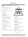
Non-functional Requirements
• Define system attributes (e.g., reliability, response time) and
constraints (e.g., MTTF e•5K transactions, response time d•2
seconds).
• Attributes are often emergent system properties : i.e., only
observable when the entire system is operational.
• Process constraints may mandate a particular CASE system,
programming language, or development method.
• Non-functional requirements may be more critical than
functional requirements. If not met, the system may be
useless.
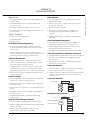
Non-functional Classifications
• Product requirements : specify product behaviour
• Organizational requirements : derived from policies /
procedures in customer’s or developer’s organization (e.g.,
process constraints)
• External requirements : derived from factors external to the
product and its development process (e.g., interoperability
requirements, legislative requirements)
Non-functional Classifications
No n-fu nctio nal
requ ir ements
Pro du ct
requ ir ements
Ef ficiency
requir ements
Reliab ility
requ ir ements
Usab ility
requ irements
Performance
requ irements
Or ganizatio nal
requ ir ements
Po rtability
requirements
Delivery
requirements
Space
requ ir ement s
Extern al
requirements
Interoperab ility
requirements
Implementation
requ ir ements
Ethical
requirements
Stand ards
requirements
Legislative
requirements
Privacy
requirements
Safety
requirements
21
SOFTWARE ENGINEERING
Functional and Non-functional Requirements
• Functional requirements : services the system should
provide, how it should react to particular inputs, or how it
should behave in particular situations.
• Non-functional requirements : constraints on services or
functions (e.g., response time) or constraints on
development process (e.g., use of a particular CASE toolset).
• Domain requirements : functional or non-functional
requirements derived from application domain (e.g., legal
requirements or physical laws
SOFTWARE ENGINEERING
Examples
•
Product requirement: 4.C.8 it shall be possible for all
necessary communication between the APSE and the user to
be expressed in the standard Ada character set.
•
•
Organisational requirement: 9.3.2 the system development
process and deliverable documents shall conform to the
process and deliverables defined in XYZCo-SP-STAN-95.
•
External requirement: 7.6.5 the system shall not disclose any
personal information about customers apart from their
name and reference number to the operators of the system.
Goals Versus Requirements
• General goals such as “system should be user friendly” or
“system should have fast response time” are not verifiable.
• Goals should be translated into quantitative requirements
that can be objectively tested.
Examples
•
A system goal: The system should be easy to use by
experienced controllers and should be organized in such a
way that user errors are minimized.
•
A verifiable non-functional requirement: Experienced
controllers shall be able to use all the system functions after a
total of two hours training. After this training, the average
number of errors made by experienced users shall not exceed
two per day.
Requirements Measures
Property
Speed
Size
Ease of use
Reliability
Robustness
Portability
Measure
Processed transactions/second
User/Event response time
Screen refresh time
K Bytes
Number of RAM chips
Training time
Number of help frames
Mean time to failure
Probability of unavailability
Rate of failure occurrence
Availability
Time to restart after failure
Percentage of events causing failure
Probability of data corruption on failure
Percentage of target dependent statements
Number of target systems
Requirement Interactions
• Competing / conflicting requirements are common with
complex systems.
• Spacecraft system example:
To minimize weight, the number of chips in the unit should
be minimized.
To minimize power consumption, low-power chips should be
used.
But using low-power chips means that more chips have to be
used. Which is the most critical requirement?
22
For this reason, preferred points in the solution space
should be identified.
Domain Requirements
• Derived from the application domain rather than user needs.
• May be new functional requirements or constraints on
existing requirements.
• If domain requirements are not satisfied, the system may be
unworkable.
Library System Domain Requirements
• There shall be a standard user interface to all databases, which
shall be based on the Z39.50 standard.
• Because of copyright restrictions, some documents must be
deleted immediately on arrival. Depending on the user’s
requirements, these documents will either be printed locally
on the system server for manually forwarding to the user or
routed to a network printer.
Train Protection System Domain Requirement
• The deceleration of the train shall be computed as:
Dtrain = Dcontrol + Dgradient
where Dgradient is 9.81m/s2 * compensated gradient/alpha
and where the values of 9.81m/s2 /alpha are known for
different types of train.
Domain Requirements Problems
• Understandability : requirements are expressed in the
language of the application domain and may not be
understood by software engineers.
• Implicitness : domain experts may not communicate such
requirements because they are so obvious (to the experts).
User Requirements “Shoulds”
• Should be understandable by system users who don’t have
detailed technical knowledge.
• Should only specify external system behaviour.
• Should be written using natural language, forms, and simple
intuitive diagrams.
Some Potential Problems With Using Natural
Language
• Lack of clarity : expressing requirements precisely is difficult
without making the document wordy and difficult to read.
• Requirements confusion : functions, constraints, goals, and
design info may not be clearly distinguished.
• Requirements amalgamation : several different requirements
may be lumped together.
Guidelines For Writing User Requirements
• Adopt a standard format and use it for all requirements.
• Use language in a consistent way. E.g., use shall for
mandatory requirements, should for desirable requirements.
• Use text highlighting to identify key parts of the
requirement.
• Avoid the use of computer jargon.
System Requirements And Design Information
• In principle, system requirements should state what the
system should do, and not how it should be designed.
• In practice, however, some design info may be incorporated,
since:
Sub-systems may be defined to help structure the requirements.
Interoperability requirements may constrain the design.
Use of a specific design model may be a requirement
More Potential Problems With Using Natural
Language
• Ambiguity : the readers and writers of a requirement must
interpret the same words in the same way. NL is naturally
ambiguous so this is very difficult.
• Over-flexibility : the same requirement may be stated in a
number of different ways. The reader must determine when
requirements are the same and when they are different.
• Lacks of modularisation : NL structures are inadequate to
structure system requirements sufficiently.
Alternatives to NL Specification
Notation
Structured
natural
language
Design
description
languages
Graphical
notations
Mathematical
specifications
Description
This approach depends on defining standard forms or
templates to express the requirements specification.
This approach uses a language like a programming
language but with more abstract features to specify the
requirements by defining an operational model of the
system.
A graphical language, supplemented by text annotations is
used to define the functional requirements for the system.
An early example of such a graphical language was SADT
(Ross, 1977; Schoman and Ross, 1977). More recently,
use-case descriptions (Jacobsen, Christerson et al., 1993)
have been used. I discuss these in the following chapter.
These are notations based on mathematical concepts
such as finite-state machines or sets. These unambiguous
specifications reduce the arguments between customer
and contractor about system functionality. However, most
customers don’t understand formal specifications and are
reluctant to accept it as a system contract. I discuss formal
specification in Chapter 9.
Program Description Languages (PDLs)
• Requirements are specified operationally using pseudo-code.
• Shows what is required by illustrating how the requirements
could be satisfied.
• Especially useful when specifying a process that involves an
ordered sequence of actions, or when describing hardware
and software interfaces.
Part of an ATM Specification
SOFTWARE ENGINEERING
System Requirements
• More detailed descriptions of user requirements
• May serve as the basis for a contract
• Starting point for system design & implementation
• May utilize different system models such as object or
dataflow
class ATM {
// declarations here
public static void main (String args[]) throws InvalidCard {
try {
thisCard.read () ; // may throw InvalidCard exception
pin = KeyPad.readPin () ; attempts = 1 ;
while ( !thisCard.pin.equals (pin) & attempts < 4 )
{
pin = KeyPad.readPin () ; attempts = attempts + 1 ;
}
if (!thisCard.pin.equals (pin))
throw new InvalidCard ("Bad PIN");
thisBalance = thisCard.getBalance () ;
do { Screen.prompt (" Please select a service ") ;
service = Screen.touchKey () ;
switch (service) {
case Services.withdrawalWithReceipt:
receiptRequired = true ;
PDL Disadvantages
•
PDL may not be sufficiently expressive to illustrate
requirements in a concise an understandable way.
•
Notation is only understandable to people with
programming language knowledge.
•
The specification may be taken as a design prescription rather
than a model to facilitate requirements understanding.
Interface Specification
• Used to specify operating interfaces with other systems.
Procedural interfaces
Data structures that are exchanged
Data representations
• Also used to specify functional behaviour.
• Formal notations are effective for interface specification – e.g.,
pre- and post-conditions
PDL Interface Description
Example: Interface and Operational Specifications of a
Function
interface PrintServer {
// defines an abstract printer server
// requires: interface Printer, interface PrintDoc
// provides: initialize, print, displayPrintQueue, cancelPrintJob, switchPrinter
void initialize ( Printer p ) ;
void print ( Printer p, PrintDoc d ) ;
void displayPrintQueue ( Printer p ) ;
void cancelPrintJob (Printer p, PrintDoc d) ;
void switchPrinter (Printer p1, Printer p2, PrintDoc d) ;
} //PrintServer
Function: Set BIG to the largest value in array A [1.. N]
Interface Specification
Pre-condition: N > 1
Post-condition: there exists an i in [1,N] such that BIG=A [i]
& for every in [1,N], BIG > A [j] & A is unchanged
23
SOFTWARE ENGINEERING
•
Operational Specification
if N e•1 then do
BIG: = A [1]
for i = 2 to N do
if A [i] > BIG then BIG: = A [i] end if
end for
end if
The Requirements Document (SRS)
• The official statement of what is required of the system
developers.
• Should include both user and system requirements.
• NOT a design document. As much as possible, it should set
out WHAT the system should do rather than HOW it
should do it.
Users of a Requirements Document
S y st e m c us to m e r s
S pe c i f y t he r e q uir e m e n ts a nd
r e a d th e m to c h e c k t ha t t he y
m e e t th e ir n e e ds . T h e y
s pe c if y c h a ng e s t o th e
r e qu ir e m e n ts
M a na g e r s
U s e t he r e q ui r e m e nt s
d o c um e n t to pl a n a bi d f or
t he s ys te m a n d to pl a n th e
sy st e m de v e lo pm e n t p r oc e s s
S y st e m e ng in e e r s
U s e t he r e q ui r e m e nt s to
un de r s ta n d w h a t s ys te m i s to
b e de v e lo p e d
S y st e m te s t
e ng in e e r s
U s e t he r e q u i r e m e nt s to
d ev e lo p va l id a ti on te s ts f o r
t he s ys te m
S y st e m
m a in te n a nc e
e ng in e e r s
U s e t he r e q u i r e m e nt s to he l p
u nd er s ta n d th e sy st e m a n d
t he r e l a ti on sh ip s b e tw e e n it s
p ar t s
Requirements Document Requirements
• Specify external system behaviour
• Specify implementation constraints
• Easy to change (!)
• Serve as reference tool for maintenance
• Record forethought about the life cycle of the system i.e.
predict changes
• Characterise responses to unexpected events
IEEE Requirements Standard
• Introduction
• General description
• Specific requirements
• Appendices
• Index
24
This is a generic structure that must be instantiated for
specific systems
Requirements Document Structure
• Preface (readers, version, change history)
• Introduction
• Glossary
• User requirements definition
• System requirements specification
• System models
• System evolution
• Appendices
• Index
Key Points
•
Requirements set out what the system should do and define
constraints on its operation and implementation.
•
Functional requirements set out services the system should
provide
•
Non-functional requirements constrain the system being
developed or the development process
•
User requirements are high-level statements of what the
system should do
•
User requirements should be written in natural language,
tables and diagrams.
•
System requirements are intended to communicate the
functions that the system should provide.
•
System requirements may be written in structured natural
language, a PDL or in a formal language.
•
A software requirements document (SRS) is the agreed
statement of system requirements
Activity
Discuss the problems of using natural language for defining
user and system requirements and show, using small examples,
how structuring natural language into forms can help avoid
some of these difficulties.
Activity
Discuss ambiguities or omissions in the following statements
of requirements for part of a ticket issuing system.
Write system requirements for the above system using a Java
based notation. You may make any reasonable assumptions
about the system. Pay particular attention to specifying user
errors.
An automated ticket issuing system sells rail tickets. Users select
their destination, and input a credit card and a personal
identification number. The rail ticket is issued and their credit
card account charged with its cost. When the user presses the
start button, a menu display of potential destinations is
activated along with a message to the user to select a destination. Once a destination has been selected, users are requested to
input their credit card. Its validity is checked and the user is then
requested to input a personal identifier. When the credit
transaction has been validated, the ticket is issued.
SOFTWARE ENGINEERING
Activity
Activity
Using the technique suggested here where natural language is
presented in a standard way, write plausible user requirements
for the following functions:
•
An unattended petrol (gas) pump system that includes a
credit card reader. The customer swipes the card through the
reader then specifies the amount of fuel required. The fuel is
delivered and the customer’s account debited.
•
The cash dispensing functioning a bank auto teller machine.
•
The spell checking and correcting functioning a word
processor.
Activity
Rewrite the above description using the structured approach
described in this chapter. Resolve the identified ambiguities in
some appropriate way.
25
SOFTWARE ENGINEERING
Activity
Activity
Describe three different types of non-functional requirement,
which may be placed on a system. Give examples of each of
these types of requirement.
You have taken a job with a software user who has contracted
your previous employer to develop a system for them. You
discover that your compan7y’s interpretation of the requirements is different form the interpretation taken by your
previous employer. Discuss what you should do in such a
situation. You know that the costs to your current employer
will increases in the ambiguities are not resolved. You have also
a responsibility of confidentiality to your previous employer.
Activity
Write a set of non-functional requirements for the ticket issuing
system described above, setting out its expected reliability and
its response time.
26
UNIT I
OVERVIEW AND REQUIREMENTS
LESSON 8 AND 9:
REQUIREMENTS ENGINEERING
PROCESS
•
To describe the principal requirements engineering activities
•
To introduce techniques for requirements elicitation and
analysis
•
To describe requirements validation
•
To discuss the role of requirements management in support
of other requirements engineering processes
Topics Covered
•
Feasibility studies
•
Requirements elicitation and analysis
•
Requirements validation
•
Requirements management
Requirements Engineering Processes
•
The processes used for RE vary widely depending on the
application domain, the people involved and the
organization developing the requirements.
•
However, there are a number of generic activities common to
most processes:
Feasibility study
Elicitation and Analysis
• Involves working with customers to learn about the
application domain, the services needed and the system’s
operational constraints.
• May also involve end-users, managers, maintenance
personnel, domain experts, trade unions, etc. (That is, any
stakeholders.)
Problems of Elicitation and Analysis
• Getting all, and only, the right people involved.
• Stakeholders often don’t know what they really want (“I’ll
know when I see it”).
• Stakeholders express requirements in their own terms.
• Stakeholders may have conflicting requirements.
• Requirements change during the analysis process. New
stakeholders may emerge and the business environment may
evolve.
• Organizational and political factors may influence the system
requirements.
The Elicitation and Analysis Process
Requirements elicitation and analysis
Requirements specification
Requirements validation
Feasibility Study
• Determines whether or not the proposed undertaking is
worthwhile.
• Aims to answer three basic questions:
Would the system contribute to overall organizational objectives?
Could the system be engineered using current technology and
within budget?
Could the system be integrated with other systems already in
use?
Feasibility Study Issues
• How would the organization cope if the system weren’t
implemented?
• What are the current process problems and how would the
system help with these?
• What will the integration problems be?
• Is new technology needed? New skills?
• What must be supported by the system, and what need not
be supported?
Viewpoint-oriented Elicitation
• Stakeholders represent different ways of looking at a
problem (viewpoints)
• A multi-perspective analysis is important, as there is no
single correct way to analyse system requirements.
• Provides a natural way to structure the elicitation process.
Types of Viewpoints
•
Data sources or sinks : viewpoints are responsible for
producing or consuming data. Analysis involves checking
that assumptions about sources and sinks are valid.
•
Representation frameworks : viewpoints represented by
different system models (i.e., dataflow, ER, finite state
27
SOFTWARE ENGINEERING
Objectives
CHAPTER 5
SOFTWARE ENGINEERING
•
machine, etc.). Each model yields different insights into the
system.
•
Receivers of services : viewpoints are external to the system
and receive services from it. Natural to think of end-users as
external service receivers.
Volere Requirements Process (www.volere.co.uk)
Method-based RE
• “Structured methods” to elicit, analyse, and document
requirements.
Volere Requirements Process
Volere Requirement Shell
28
Examples include:
Ross’ Structured Analysis (SA),
Knowledge Acquisition and Sharing for Requirement Engineering (KARE) (www.kare.org),
Somerville’s Viewpoint-Oriented Requirements Definition
(VORD), and
The baut’s Scenario-Based Requirements Engineering (SBRE)
SOFTWARE ENGINEERING
KARE Workbench Architecture
Somerville’s VORD Method
VORD Standard Forms
29
SOFTWARE ENGINEERING
Scenarios
• Depict examples or scripts of possible system behaviour.
• People often relate to these more readily than to abstract
statements of requirements.
• Particularly useful in dealing with fragmentary, incomplete, or
conflicting requirements.
SBRE Scenario Generation
Scenario Descriptions
• System state at the beginning of the scenario.
• Sequence of events for a specific case of some generic task the
system is required to accomplish.
• Any relevant concurrent activities.
• System state at the completion of the scenario.
A Simple Scenario
• t0: The user enters values for input array A. The values are
[1, 23, -4, 7, 19]. The value of output variable BIG remains
‘undefined’.
• t1: The user executes program MAX.
• t2: The value of variable BIG is 23 and the values of A are
[1, 23, -4, 7, 19].
Scenario-Based Requirements Engineering (SBRE)
• Marcel support environment allows rapid construction of an
operational specification of the desired system and its
environment.
• Based on a forward chaining rule-based language.
• An interpreter executes the specification to produce natural
language based scenarios of system behavior.
Scenario Representation in VORD
• VORD supports the graphical description of multi-threaded
“event scenarios” to document system behaviour:
Data provided and delivered
Control information
Exception processing
The next expected event
• Multi-threading supports description of exceptions.
Scenario for a “Start Transaction” Event
SBRE Rule Template
UML Use-cases and Sequence Diagrams
• Use-cases are a graphical notation for representing abstract
scenarios in the UML.
• They identify the actors in an interaction and describe the
interaction itself.
• A set of use-cases should describe all types of interactions
with the system.
• Sequence diagrams may be used to add detail to use-cases by
showing the sequence of event processing.
30
incomplete information so that the system will fail.
Ethnography
• A social scientists spends considerable time observing and
analysing how people actually work.
• People do not have to explain or articulate what they do.
• Social and organizational factors of importance may be
observed.
• Ethnographic studies have shown that work is usually richer
and more complex than suggested by simple system models.
Focused Ethnography
• Developed during a project studying the air traffic control
process.
• Combines ethnography with prototyping.
• Prototype development raises issues: which focus the
ethnographic analysis.
• Problem with ethnography alone: it studies existing practices,
which may not be relevant when a new system is put into
place.
Catalogue Management Sequence Diagram
Requirements Validation
• Concerned with whether or not the requirements define a
system that the customer really wants.
• Requirements error costs are high, so validation is very
important. (Fixing a requirements error after delivery may
cost up to 100 times that of fixing an error during
implementation.)
Requirements Checking
• Validity: Does the system provide the functions which best
support the customer’s needs?
• Consistency: Are there any requirements conflicts?
• Completeness: Are all functions required by the customer
included?
• Realism: Can the requirements be implemented given
available budget and technology?
• Verifiability: Can the requirements be tested?
Social and Organizational Factors
• All software systems are used in a social and organizational
context. This can influence or even dominate the system
requirements.
• Good analysts must be sensitive to these factors, but there is
currently no systematic way to tackle their analysis.
Example
• Consider a system: which allows senior management to
access information without going through middle managers.
• Managerial status: Senior managers may feel that they are too
important to use a keyboard. This may limit the type of
system interface used.
• Managerial responsibilities: Managers may have no
uninterrupted time when they can learn to use the system
• Organizational resistance: Middle managers who will be
made redundant may deliberately provide misleading or
Requirements Validation Techniques
• Requirements reviews / inspections : systematic manual
analysis of the requirements.
• Prototyping : using an executable model of the system to
check requirements.
• Test-case generation : developing tests for requirements to
check testability.
• Automated consistency analysis : checking the consistency of
a structured requirements description.
Requirements Reviews / Inspections
• Regular reviews should be held while the requirements
definition is being formulated.
• Both client and contractor staff should be involved in
reviews. (Stakeholders)
• Reviews may be formal (with completed documents) or
informal. Good communications between developers,
customers and users can resolve problems at an early stage.
31
SOFTWARE ENGINEERING
Library Use-cases
SOFTWARE ENGINEERING
Review Check-list
• Verifiability: Is the requirement realistically testable?
• Comprehensibility: Is the requirement properly understood?
• Traceability: Is the origin of the requirement clearly stated?
• Adaptability: Can the requirement be changed with
minimum impact on other requirements? (Especially when
change is anticipated!)
Requirements Management
• Requirements management is the process of managing
changing requirements during the requirements engineering
process and system development.
• New requirements emerge during the process as business
needs change and a better understanding of the system is
developed.
• The priority of requirements from different viewpoints
changes during the development process.
• The business and technical environment of the system
changes during its development.
Enduring and Volatile Requirements
• Enduring requirements: Stable requirements derived from
the core activity of the customer organization. E.g., a
hospital will always have doctors, nurses, etc. May be derived
from domain models.
• Volatile requirements: Requirements which change during
development or when the system is in use. E.g.,
requirements derived from the latest health-care policy.
Classification of Requirements
• Mutable requirements : those that change due to changes in
the system’s environment.
• Emergent requirements : those that emerge as understanding
of the system develops.
• Consequential requirements : those that result from the
introduction of the system.
• Compatibility requirements : those that depend on other
systems or organizational processes.
Requirements Management Planning
• During requirements management planning, you must
decide on:
• Requirements identification : how requirements will be
individually identified.
• A change management process : a process to be followed
when analysing the impact and costs of a requirements
change.
• Traceability policies : the amount of information about
requirements relationships that is maintained.
• CASE tool support : the tool support required to help
manage requirements change.
Traceability
• Traceability is concerned with the relationships between
requirements, their sources, and the system design.
32
•
Source traceability : links from requirements to stakeholders
who proposed these requirements.
•
Requirements traceability : links between dependent
requirements.
•
Design traceability : links from the requirements to the
design.
CASE Tool Support
• Requirements storage : requirements should be managed in a
secure, managed data store.
• Change management : the process of change management is
a workflow process whose stages can be defined and
information flow between the stages partially automated.
• Traceability management : automated discovery and
documentation of relationships between requirements
Requirements Change Management
• Should apply to all proposed changes to the requirements.
• Principal stages:
Problem analysis : discuss identified requirements problem and
propose specific change(s).
Change analysis and costing : assess effects of change on other
requirements.
Change implementation : modify requirements document and
others to reflect change.
Requirements Change Management
Key Points
•
The requirements engineering process includes a feasibility
study, elicitation and analysis, specification, and validation.
•
Requirements analysis is an iterative process involving
domain understanding, requirements collection,
classification, structuring, prioritization and validation.
•
Systems have multiple stakeholders with different
viewpoints and requirements.
•
Social and organization factors influence system
requirements.
•
Requirements validation is concerned with checks for validity,
consistency, complete-ness, realism, and verifiability.
•
Business, organizational, and technical changes inevitably
lead to changing requirements.
•
Requirements management involves careful planning and a
change management process.
Suggest who might be stakeholders in a university student
records system. Explain why it is almost inevitable that the
requirements of different stakeholders will conflict in some
ways.
Activity
For three of the viewpoints identified in the library cataloguing
system, suggest services which might be provided to that
viewpoint, data which the viewpoint might provide and events
which control the delivery of these services.
Activity
A software system is to be developed to automate a library
catalogue. This system will contain information about all the
books in a library and will be usable by library staff and by book
borrows and reasons the system should support catalogue
browsing, querying, and should provide facilities allowing users
to send messages to library staff reserving a book which is on
loan. Identify the principal viewpoints, which might be taken
into account in the specification of this system and show their
relationships using a viewpoint hierarchy diagram.
Activity
Using your own knowledge of how an ATM is used, develop a
set of use cases that could be used to derive the requirements
for an ATM system.
33
SOFTWARE ENGINEERING
Activity
SOFTWARE ENGINEERING
Activity
Activity
Discuss an example of a type of system where social and
political factors might strongly influence the system requirements. Explain why these factors are important in your
example.
Why do tractability matrices become difficult to mange when
there are many system requirements? Design a requirements
structuring mechanism, based on viewpoints, which might help
reduce the scale of this problem.
Activity
Activity
Who should be involved in a requirements review? Draw a
process model showing how a requirements review might be
organized.
34
When emergency changes have to be made to system software
may have to be modified before changes to the requirements
have been approved. Suggest a model of a process for making
these modifications, which ensures that the requirements
document and the system implementation do not become
inconsistent.
SOFTWARE ENGINEERING
Activity
Your company uses a standard analysis method which is
normally applied in all requirements analyses. In your work, you
find that this method cannot represent social factors, which are
significant in the system you are analyzing. You point out to
your manager who makes clear that the standard should be
followed. Discuss what you should do in such a situations.
Notes:
35
UNIT I
OVERVIEW AND REQUIREMENTS
LESSON 10 AND 11:
SYSTEM MODELS
SOFTWARE ENGINEERING
Abstract Descriptions of Systems Whose
Requirements are Being Analysed
Objectives
•
To explain why the context of a system should be modelled
as part of the RE process
•
To describe behavioural modelling, data modelling and
object modelling
•
To introduce some of the notations used in the Unified
Modelling Language (UML)
•
To show how CASE workbenches support system
modelling
Topics Covered
•
•
•
•
•
Context models
Behavioural models
Data models
Object models
CASE workbenches
System Modelling
• System modelling helps the analyst to understand the
functionality of the system and models are used to
communicate with customers
• Different models present the system from different
perspectives
External perspective showing the system’s context or environment
Behavioural perspective showing the behaviour of the system
Structural perspective showing the system or data architecture
Structured Methods
• Structured methods incorporate system modelling as an
inherent part of the method
• Methods define a set of models, a process for deriving these
models and rules and guidelines that should apply to the
models
• CASE tools support system modelling as part of a
structured method
Method Weaknesses
• They do not model non-functional system requirements
• They do not usually include information about whether a
method is appropriate for a given problem
• The may produce too much documentation
• The system models are sometimes too detailed and difficult
for users to understand
36
UNIT 3
CHAPTER 6
Model Types
• Data processing model showing how the data is processed at
different stages
• Composition model showing how entities are composed of
other entities
• Architectural model showing principal sub-systems
• Classification model showing how entities have common
characteristics
• Stimulus/response model showing the system’s reaction to
events
Context Models
• Context models are used to illustrate the boundaries of a
system
• Social and organisational concerns may affect the decision on
where to position system boundaries
• Architectural models show the a system and its relationship
with other systems
The Context of An ATM System
Security
system
Branch
accounting
system
Account
database
Auto-teller
system
Branch
counter
system
Usage
database
Maintenance
system
Process Models
•
Process models show the overall process and the processes
that are supported by the system
•
Data flow models may be used to show the processes and
the flow of information from one process to another
•
Delivery
note
Specify
equipment
requir ed
Equipment
spec.
Equipment
spec.
Supplier
database
Checked
spec.
Validate
specification
Accept
delivery of
equipment
Get cost
estimates
Supplier list
Find
suppliers
Spec. +
supplier +
estimate
Choose
supplier
CASE Toolset DFD
Delivery
note
Check
delivered
items
Input
d esig n
Valid
des ign
Place
equipment
order
Accept
delivered
equipment
Equipment
details
Equipment
database
Behavioural Models
• Behavioural models are used to describe the overall
behaviour of a system
• Two types of behavioural model are shown here
Data-processing models that show how data is processed as it
moves through the system
State machine models that show the systems response to events
• Both of these models are required for a description of the
system’s behaviour
Data-processing Models
• Data flow diagrams are used to model the system’s data
processing
• These show the processing steps as data flows through a
system
• Intrinsic part of many analysis methods
• Simple and intuitive notation that customers can understand
• Show end-to-end processing of data
Des ign
cro ss checker
Referenced
desig ns
Install
equipment
and
Desig n
analys is
Desig n
analy ser
Checked
des ign
Desig n
datab ase
Installation
acceptance
Checked and
signed order form
Ch eck ed
desig n
Design
edito r
Installation
instructions
Order
notification
Order
details +
Blank order
form
Data flow diagrams may also be used in showing the data
exchange between a system and other systems in its
environment
Code skelet on
generator
User
report
Repo rt
gen erator
Out put
cod e
Desig n
database
State Machine Models
• These model the behaviour of the system in response to
external and internal events
• They show the system’s responses to stimuli so are often
used for modelling real-time systems
• State machine models show system states as nodes and
events as arcs between these nodes. When an event occurs,
the system moves from one state to another
• State charts are an integral part of the UML
Microwave Oven Model
Full
power
Full power
do: set power
= 600
Timer
Waiting
do: display
time
Half
power
Full
power
Half
power
Set time
do: get number
exit: set time
Timer
Half power
do: set power
= 300
Number
Operation
do: operate
oven
Door
closed
Door
open
Door
closed
Cancel
Start
Enabled
do: display
'Ready'
Door
open
Waiting
do: display
time
Disabled
do: display
'Waiting'
Order Processing DFD
Microwave Oven State Description
Order
details +
blank
order form
Completed
order form
Complete
order form
Signed
order form
Validate
order
Signed
order form
Send to
supplier
Record
order
Order
details
Signed
order form
Checked and
signed order
+ order
notification
Full power
Adjust
available
budget
Set time
Order
amount
+ account
details
Orders
file
State
Waiting
Half power
Budget
file
Data Flow Diagrams
• DFDs model the system from a functional perspective
• Tracking and documenting how the data associated with a
process is helpful to develop an overall understanding of the
system
Disabled
Enabled
Operation
Description
The oven is waiting for input. The display shows the current time.
The oven power is set to 300 watts. The display shows ‘Half
power’.
The oven power is set to 600 watts. The display shows ‘Full
power’.
The cooking time is set to the user’s input value. The display
shows the cooking time selected and is updated as the time is set.
Oven operation is disabled for safety. Interior oven light is on.
Display shows ‘Not ready’.
Oven operation is enabled. Interior oven light is off. Display
shows ‘Ready to cook’.
Oven in operation. Interior oven light is on. Display shows the
timer countdown. On completion of cooking, the buzzer is
sounded for 5 seconds. Oven light is on. Display shows ‘Cooking
complete’ while buzzer is sounding.
37
SOFTWARE ENGINEERING
Equipment Procurement Process
SOFTWARE ENGINEERING
Software Design Semantic Model
Microwave Oven Stimuli
Stimulus
Half power
Full power
Timer
Number
Door open
Door closed
Start
Cancel
Description
The user has pressed the half power button
The user has pressed the full power button
The user has pressed one of the timer buttons
The user has pressed a numeric key
The oven door switch is not closed
The oven door switch is closed
The user has pressed the start button
The user has pressed the cancel button
State Charts
• Allow the decomposition of a model into sub-models (see
following slide)
• A brief description of the actions is included following the
‘do’ in each state
• Can be complemented by tables describing the states and the
stimuli
Microwave Oven Operation
Operation
Checking
do: check
status
Turntable
fault
Time
Cook
do: run
generator
OK
Emitter
fault
Timeout
do: display
event
1
Disabled
n
1
No de
n am e
typ e
h as -li nk s
1
2
Link
n
1
l in ks
n am e
t yp e
1
1
h as -la b els
h as -lab els
Lab el
n
n am e
tex t
ico n
n
Data Dictionaries
• Data dictionaries are lists of all of the names used in the
system models. Descriptions of the entities, relationships
and attributes are also included
• Advantages
Support name management and avoid duplication
Store of organisational knowledge linking analysis, design and
implementation
• Many CASE workbenches support data dictionaries
Name
has-labels
Cancel
Waiting
Link
Semantic Data Models
• Used to describe the logical structure of data processed by
the system
• Entity-relation-attribute model sets out the entities in the
system, the relationships between these entities and the
entity attributes
• Widely used in database design. Can readily be implemented
using relational databases
• No specific notation provided in the UML but objects and
associations can be used
name
(label)
name
(node)
Description
1:N relation between entities of type
Node or Link and entities of type
Label.
Holds structured or unstructured
information about nodes or links.
Labels are represented by an icon
(which can be a transparent box) and
associated text.
A 1:1 relation between design
entities represented as nodes. Links
are typed and may be named.
Each label has a name which
identifies the type of label. The na me
must be unique within the set of label
types used in a design.
Each node has a name which must be
unique within a design. The name
may be up to 64 characters long.
Type
Date
Relation
5.10.1998
Entity
8.12.1998
Relation
8.12.1998
Attribute
8.12.1998
Attribute
15.11.1998
Object Models
• Object models describe the system in terms of object classes
•
An object class is an abstraction over a set of objects with
common attributes and the services (operations) provided
by each object
•
Various object models may be produced
Inheritance models
38
h as -link s
1
n
Label
Door
open
i s-a
h as -no des
1
Data Dictionary Entries
Done
do: buzzer on
for 5 secs.
Alarm
Des ig n
n am e
d es crip tion
C -d ate
M -dat e
SOFTWARE ENGINEERING
User Class Hierarchy
Aggregation models
Interaction models
•
•
Natural ways of reflecting the real-world entities manipulated
by the system
Libr ary us er
Nam e
Ad d ress
Ph on e
Regi st rat io n #
More abstract entities are more difficult to model using this
approach
•
Object class identification is recognised as a difficult process
requiring a deep understanding of the application domain
•
Object classes reflecting domain entities are reusable across
systems
Inheritance Models
• Organise the domain object classes into a hierarchy
• Classes at the top of the hierarchy reflect the common
features of all classes
• Object classes inherit their attributes and services from one
or more super-classes. These may then be specialised as
necessary
• Class hierarchy design is a difficult process if duplication in
different branches is to be avoided
The Unified Modelling Language
• Devised by the developers of widely used object-oriented
analysis and design methods
• Has become an effective standard for object-oriented
modelling
• Notation
Object classes are rectangles with the name at the top, attributes
in the middle section and operations in the bottom section
Relationships between object classes (known as associations) are
shown as lines linking objects
Inheritance is referred to as generalisation and is shown
‘upwards’ rather than ‘downwards’ in a hierarchy
Library Class Hierarchy
Regi st er ()
De-r egi st er ()
Reader
Bo rro wer
Item s o n l oan
M ax. lo ans
Affil iatio n
St aff
St ud ent
Dep artm en t
Dep artm en t ph on e
M ajo r s ub ject
Ho m e ad d ress
Multiple Inheritance
• Rather than inheriting the attributes and services from a
single parent class, a system, which supports multiple
inheritance, allows object classes to inherit from several
super-classes
• Can lead to semantic conflicts where attributes/services with
the same name in different super-classes have different
semantics
• Makes class hierarchy reorganisation more complex
Book
Voice recording
Author
Edition
Publication date
ISBN
Speaker
Duration
Recording date
Library i tem
Catalog ue n u mber
Acq ui si ti on d ate
Co st
Ty pe
St at us
Nu mb er of co pi es
Talking book
Acq uire ()
Catal ogu e ()
Dis po se ()
Issu e ()
Return ()
# Tapes
Pu bl is hed item
Record ed i tem
T i tl e
M edium
Ti tl e
Pub li sh er
Bo ok
Au th or
Edition
Publ icat io n d at e
ISBN
M ag azi ne
Year
Iss u e
Fi lm
Directo r
Dat e of releas e
Dis tri buto r
Co mpu ter
p ro g ram
Object Aggregation
• Aggregation model shows how classes, which are collections,
are composed of other classes
• Similar to the part-of relationship in semantic data models
Version
Pl at fo rm
39
SOFTWARE ENGINEERING
Object Behaviour Modelling
• A behavioural model shows the interactions between objects
to produce some particular system behaviour that is specified
as a use-case
• Sequence diagrams (or collaboration diagrams) in the UML
are used to model interaction between objects
Issue of Electronic Items
Ec at :
C a ta l og
Li b1 :
N et S er ve r
: Lib ra ry Ite m
: Lib ra ry Us e r
Lo ok up
D i s pl ay
Iss u e
Iss u e li c enc e
Ac c ep t li ce nce
C o m pre ss
De l iv e r
CASE Workbenches
• A coherent set of tools that is designed to support related
software process activities such as analysis, design or testing
• Analysis and design workbenches support system modelling
during both requirements engineering and system design
• These workbenches may support a specific design method or
may provide support for a creating several different types of
system model
An Analysis and Design Workbench
Data
dictionary
Structured
diagramming
tools
Report
generation
facilities
Code
generator
Central
information
repository
Query
language
facilities
Forms
creation
tools
Design, analysis
and checking
tools
Import/export
facilities
Analysis Workbench Components
• Diagram editors
• Model analysis and checking tools
• Repository and associated query language
• Data dictionary
• Report definition and generation tools
40
•
•
•
Forms definition tools
Import/export translators
Code generation tools
Key Points
• A model is an abstract system view. Complementary types of
model provide different system information
• Context models show the position of a system in its
environment with other systems and processes
• Data flow models may be used to model the data processing
in a system
• State machine models model the system’s behaviour in
response to internal or external events
• Semantic data models describe the logical structure of data,
which is imported to or exported by the systems
• Object models describe logical system entities, their
classification and aggregation
• Object models describe the logical system entities and their
classification and aggregation
• CASE workbenches support the development of system
models
Activity
Draw a context model for a patient information system in a
hospital. You may make any reasonable assumptions about the
other hospital systems, which are available, but your model
must include a patient admissions system and an image storage
system for X-rays.
Activity
Based on your experience with a bank ATM, draw a data-flow
diagram modeling the data processing involved when a
customer withdraws cash form the machine.
Draw state machine models of the control software for:
•
An automatic washing machine, which has different
programs for different types of clothes.
•
•
The software for ac compact disc player.
SOFTWARE ENGINEERING
Activity
A telephone answering machine on an LED display. The
system should allow the telephone owner to dial in, type a
sequence of numbers (identified as tones) and have the
recorded messages replayed over the phone.
Activity
Model the data processing which might take place in an
electronic mail system. You should model the mail sending and
mail receiving processing separately.
Activity
Develop an object model including a class hierarchy diagram and
an aggregation diagram showing the principal components of a
personal computer system and its system software.
41
SOFTWARE ENGINEERING
Activity
Develop a sequence diagram showing the interactions involved
when a student registers for a course in a university. Courses
may have a limited number of places so the registration process
must include checks that places are available. Assume that the
student accesses an electronic course catalogue to find out about
available courses.
Activity
Describe three modeling activities that may be supported by a
CASE workbench for some analysis method. Suggest three
activities that cannot be automated.
42
Notes -
UNIT I
OVERVIEW AND REQUIREMENTS
LESSSON 12 AND 13:
SOFTWARE PROTOTYPING
Throw-away prototyping : to elicit and validate requirements
•
To describe the use of prototypes in different types of
development projects
Evolutionary prototyping : to deliver an acceptable, working
system to end-users
•
To discuss evolutionary and throw-away prototyping
Experimental prototyping : to evaluate proposed solutions for
feasibility, performance, etc.
To introduce three rapid prototyping techniques:
High-level language development,
Database programming, and
Component reuse
•
Simulation, Prototyping and Scenarios
• What are the differences between prototyping and
simulation?
To explain the need for user interface prototyping
Topics Covered
•
•
•
Prototyping in the software process
Rapid prototyping techniques
User interface prototyping
What is Prototyping?
• Some traditional features:
An iterative process emphasizing
Rapid development,
Evaluative use,
Feedback, and
Modification
Learning (based on feedback)
Consideration of alternatives
Concreteness (a “real system” is developed and presented to real
users)
• Boundary between prototyping and normal system
development blurs when an evolutionary (e.g., agile)
development approach is used.
Uses of Prototypes
• Principal use is to help customers and developers better
understand system requirements.
Experimentation stimulates anticipation of how a system could
be used.
Attempting to use functions together to accomplish some task
can easily reveal requirements problems.
• Other potential uses:
Evaluating proposed solutions for feasibility (Experimental
Prototyping)
“Back-to-back” system testing
Training users before system delivery
• Prototyping is most often undertaken as a risk reduction
activity.
Classifying Prototypes
• By purpose:
•
What is the connection between simulation models /
prototypes, scenarios?
Simulation models are automatic scenario generators.
Prototypes facilitate manual scenario generation.
Prototyping Benefits
• Misunderstandings exposed.
• Difficult to use or confusing services identified
• Missing services detected
• Incomplete and/or inconsistent requirements found by
analysts as prototype is being developed. Can demo
feasibility and usefulness
• Basis for writing a system specification
Prototyping Process
E s t ab l is h
p ro to ty p e
o b j ec t iv e s
D e fi ne
p ro to ty p e
f u n c ti o n a li ty
D e v e lo p
p ro to ty p e
E v a lu a t e
p ro to ty p e
P ro to ty p i n g
p la n
O u t li n e
d ef i n i ti o n
E x e c u t ab le
p ro to ty p e
E v a lu ati o n
re po r t
Prototyping Outcomes
• Improved system usability
• Closer match to the system needed
• Improved design quality (maybe…)
• Improved maintainability (maybe…)
• Reduced overall development effort (maybe…but corrective
maintenance costs are usually reduced)
43
SOFTWARE ENGINEERING
Objectives
CHAPTER 7
SOFTWARE ENGINEERING
Prototyping in The Software Process
• Evolutionary prototyping : prototype is produced and
refined through a number of stages to become the final
system.
• Throwaway prototyping : prototype is produced to help
elucidate / validate requirements and then discarded. The
system is then developed using some other development
process.
Starting Points
• In evolutionary prototyping, development starts with those
requirements, which are best understood.
• In throwaway prototyping, development starts with those
requirements, which are least understood.
Approaches to Prototyping
Ev o lu ti on ary
p ro to ty pi ng
Del i vered
s ys tem
Th row-away
P ro to ty pi ng
Execut able P rot ot yp e +
S y st em S peci ficat io n
Specialized developer skills required
•
Maintenance problems : Continual change tends to corrupt
system structure so long-term maintenance is expensive.
•
Contractual problems : No system requirements specification
to serve as basis for contract
Incremental Development Revisited
• System developed and delivered in increments after
establishing an overall architecture.
• Users experiment with delivered increments while others are
being developed.
• Intended to combine advantages of prototyping with a
more manageable process and maintainable system structure.
Incremental Development Process
Define system
deliverables
Ou t li ne
R equ irem ent s
Specify system
increment
Design system
architecture
Build system
increment
Validate
increment
Validate
system
Integrate
increment
NO
Evolutionary Prototyping
• Often used when a specification cannot be developed in
advance (e.g., AI systems and GUI applications).
• System is developed as a series of prototype versions
delivered to the customer for assessment.
• Verification is unnecessary as there is no specification.
• Validation involves assessing the adequacy of the system.
Develop abstract
specification
Build prototype
system
Use prototype
system
N
Deliver
system
YES
System
adequate?
Deliver final
system
YES
Throw-away Prototyping
• Used to reduce requirements risk.
• Initial prototype is developed from outline requirements,
delivered for experiment, and modified until risk is
acceptably low
Outline
requirements
Techniques for rapid system development are used such as
CASE tools and 4GLs.
•
User interfaces are usually developed using a GUI
development toolkit.
Advantages of Evolutionary Prototyping Over
Normal System Development
• Accelerated delivery : Quick availability is sometimes more
important than details of functionality or maintainability.
• User engagement : System is more likely to meet user
requirements and users are more likely to want to make it
work.
Evolutionary Prototyping Problems
• Management problems
Poor fit with existing waterfall management model
44
Develop
prototype
Evaluate
prototype
Specify
system
Reusable
components
Develop
software
•
System
complete?
Validate
system
Delivered
software
system
Throw-away Prototype Delivery
• Developers may be pressurized to deliver a throw-away
prototype as the final system.
• This is very problematic...
It may be impossible to meet non-functional requirements.
The prototype is almost certainly undocumented.
The system may be poorly structured and therefore difficult to
maintain.
Normal quality standards may not have been applied.
Prototypes AS Specifications?
• Some parts of the requirements (e.g., safety-critical functions)
may be impossible to prototype and so don’t appear in the
specification.
An implementation has no legal standing as a contract.
Non-functional requirements cannot be adequately
represented in a system prototype.
Implementation Techniques
• Various techniques may be used for rapid development:
Dynamic high-level language development
Database programming (4GL’s)
Component and application assembly
• These are not mutually exclusive : they are often used
together.
• Visual programming is an inherent part of most prototype
development systems.
Dynamic High-level Languages
• Include powerful data management facilities : often type less
and interpretive
• Require large run-time support system : not normally used
for large system development.
• Some offer excellent GUI development facilities.
• Some have an integrated support environment whose
facilities may be used in the prototype.
• Examples: Lisp (list structure based), Prolog (logic based),
and Smalltalk (object-oriented)
Choice of Prototyping Language
• What is the application domain? (e.g., NLP?, matrix
manipulation?)
• What user interaction is required? (text-based? Web-based?)
• What support environment comes with the language? (e.g.,
tools, components)
• What support environment comes with the language? (e.g.,
tools, components)
• Different parts of the system may be programmed in
different languages. However, there may be problems with
language communications.
• A multi-paradigm language (e.g., LOOPS) can reduce this
problem.
Database Programming Languages
• Domain specific languages for business systems based
around a database management system
• Normally include a database query language, a screen
generator, a report generator and a spreadsheet.
• May be integrated with a CASE toolset
• The language + environment is some-times known as a
fourth-generation language (4GL)
• Cost-effective for small to medium sized business systems
• Examples include Informix, Appgen, Sculptor, and Power4GL.
Interface
generator
Spreadsheet
DB
programming
lan guag e
Report
gen erator
Databas e manag ement system
Fourth-gener ation language
Component and Application Assembly
• Prototypes can be created quickly from a set of reusable
components plus some mechanism to “glue” these
components together.
• The composition mechanism must include control facilities
and a mechanism for component communication
• Must take into account the availability and functionality of
existing components
Prototyping With Reuse
• Application level development
Entire application systems are integrated with the prototype so
that their functionality can be shared.
For example, if text preparation is required, a standard word
processor can be used.
• Component level development
Individual components are integrated within a standard
framework to implement the system
Framework can be a scripting language or an integration
framework such as CORBA, DCOM, or Java Beans
Reusable Component Composition
Reusable
software
components
Component
composition
framework
Executable
prototype
Control and
integration code
Compound Documents
• For some applications, a prototype can be created by
developing a compound document.
• This is a document with active elements (such as a
spreadsheet) that allow user computations.
• Each active element has an associated application, which is
invoked when that element is selected.
• The document itself is the integrator for the different
applications.
Application Linking in Compound Documents
C om p ou nd d ocu m ent
Text 1
Table 1
Table 2
W o rd p r o c e s s o r
Text 2
T e xt 4
T e xt 3
S o un d 2
S p r ea d s h e e t
S o un d 1
Text 5
A u dio pla ye r
45
SOFTWARE ENGINEERING
•
•
SOFTWARE ENGINEERING
Visual Programming
• Scripting languages such as Visual Basic support visual
programming where the prototype is developed by creating a
user interface from standard items and associating
components with these items.
• A large library of components exists to support this type of
development
• These may be tailored to suit the specific application
requirements.
•
Prototyping is essential for parts of the system such as the
user interface, which cannot be effectively pre-specified. Users
must be involved in prototype evaluation
Activity
You have been asked to investigate the feasibility of
prototyping in the software development process in your
organization. Write a report for your manager discussing the
classes of project where prototyping should be used and setting
out the expected costs and benefits form using prototyping.
Visual Programming With Reuse
Hypertext
display component
Date component
File
Edit
Views
12th January 2000
Range checking
script
Layout
Options
Help
General
Index
3.876
User prompt
component +
script
Draw canvas
component
Tree display
component
Problems With Visual Development
• Difficult to coordinate team-based development
• No explicit system architecture (hidden)
• Complex dependencies between parts of the program can
cause maintainability problems.
User Interface Prototyping
• It is impossible to pre-specify the look and feel of a user
interface in an effective way. Prototyping is essential.
• UI development consumes an increasing part of overall
system development costs
• User interface generators may be used to “draw” the interface
and simulate its functionality with components associated
with interface entities.
• Web interfaces may be prototyped using a web site editor.
Key Points
•
A prototype can be used to give end-users a concrete
impression of the system’s capabilities.
•
Prototyping is becoming increasingly used for system
development where rapid development is essential.
•
Throw-away prototyping is used to understand the system
requirements.
•
In evolutionary prototyping, the system is developed by
evolving an initial version to the final version.
•
Rapid development of prototypes is essential. This may
require leaving out functionality or relaxing non-functional
constraints.
•
Prototyping techniques include the use of very high-level
languages, database programming and prototype
construction from reusable components.
46
Activity
Explain why, for large systems development, it is recommended
that prototypes should be throw away prototypes.
Activity
SOFTWARE ENGINEERING
Activity
Under what circumstances would you recommend that
prototyping should be used as a means of validating system
requirements?
Discuss prototyping using reusable components and suggest
problems which may arise using this approach. What is the
most effective way to specify reusable components?
Activity
Activity
Suggest difficulties that might arise when prototyping real time
embedded computer systems :
You have been asked by a charity to prototype a system that
keeps track of tall donations they have received. This system has
to maintain the names and addresses of donors, their particular
interests, the amount donated, and when it was donation (e.g.
it must be spent on a particular project) and the system must
keep track of these donations and how they were spent. Discuss
how you would prototype this system bearing in mind that the
charity has a mixture of paid workers and volunteers. Many of
the volunteers are retirees who have had little or no computer
experience.
47
SOFTWARE ENGINEERING
Activity
You have developed a throw prototype system for a client who
is very happy with it. However, she suggests that there is no
need to develop another system but that you should deliver the
prototype and offers an excellent price for the system. You
know that there may be future problems with maintaining the
system. Discuss how you might respond to this customer.
Notes:
48
UNIT I
OVERVIEW AND REQUIREMENTS
LECTURE 14:
FORMAL SPECIFICATIONS
•
To explain why formal specification helps discover problems
in system requirements.
•
To describe the use of:
Algebraic specification techniques, and
Model-based specification techniques (including simple pre and
post conditions).
Topics Covered
•
•
•
Formal specification in the software process
Interface specification
•
In systems where failure must be avoided, the use of formal
methods is justified and likely to be cost-effective.
•
Thus, the use of formal methods is increasing in critical
system development where safety, reliability, and security are
important.
Formal Specification in The Software Process
Requirements
specificatio n
Formal
specificat ion
Requ irements
defini tion
Hi gh-le vel
d es ign
Sy stem
modell ing
Ar chitect ural
des ign
Behavioural specification
Formal Methods
• Formal specification is part of a more general collection of
techniques known as “formal methods.”
• All are based on the mathematical representations and
analysis of requirements and software.
• Formal methods include:
Formal specification
Specification analysis and property proofs
Transformational development
Program verification (program correctness proofs)
• Specifications are expressed with precisely defined vocabulary,
syntax, and semantics.
Formal Specification Techniques
Acceptance and Use
• Formal methods have not become mainstream as was once
predicted, especially in the US.
Other, less costly software engineering techniques (e.g., inspections / reviews) have been successful at increasing system
quality. (Hence, the need for formal methods has been reduced.)
Market changes have made time-to-market rather than quality
the key issue for many systems. (Formal methods do not reduce
time-to-market.)
The scope of formal methods is limited. They are not well
suited to specifying user interfaces. (Many interactive applications are “GUI-heavy” today.)
Formal methods are hard to scale up to very large systems.
(Although this is rarely necessary.)
The costs of introducing formal methods are high.
Thus, the risks of adopting formal methods on most projects
outweigh the benefits.
• However, formal specification is an excellent way to find
requirements errors and to express requirements
unambiguously.
• Projects, which use formal methods invariably, report fewer
errors in the delivered software.
Formal Specification Languages
Algebraic approach : the system is specified in terms of its
operations and their relationships via axioms.
Model-based approach (including simple pre- and postconditions) : the system is specified in terms of a state model
and operations are defined in terms of changes to system state.
Use of Formal Specification
• Formal specification is a rigorous process and requires more
effort in the early phases of software development.
• This reduces requirements errors as ambiguities,
incompleteness, and inconsistencies are discovered and
resolved.
• Hence, rework due to requirements problems is greatly
reduced.
49
SOFTWARE ENGINEERING
Objectives
CHAPTER 8
SOFTWARE ENGINEERING
Development Costs With Formal Specification
C o st
Vali da t io n
De s ig n and
Im pl em ent a t io n
•
(System State) Model-based specification exposes the system
state and defines operations in terms of changes to that
state.
•
Z is a mature notation for model-based specification. It
combines formal and informal descriptions and incorporates
graphical highlighting.
•
The basic building blocks of Z-based specifications are
schemas.
•
Schemas identify state variables and define constraints and
operations in terms of those variables.
Va li dat io n
Des ig n a nd
Im pl em e nt at io n
S p e ci fic at io n
S p e ci fica t io n
The Structure of A Z Schema
W i th ou t fo rm a l
s pe cifi c at io n
Schema name
W i th fo rm al
s pec ifi ca t io n
Schema signature
Schema predicate
Natural numbers (0, 1, 2, …)
Specification of Sub-system Interfaces
• Large systems are normally comprised of sub-systems with
well-defined interfaces.
• Specification of these interfaces allows for their independent
development.
• Interfaces are often defined as abstract data types or objects.
• The algebraic approach is particularly well suited to the
specification of such interfaces.
Container
contents:
capacity:
Defines schema state
contents <
Š capacity
“invariants”, pre- & postconditions
An Insulin Pump
Insulin reservoir
Needle
assembly
Sub-system Interfaces
insulin
Sensor
S u b-s ys te m
B
Specification Components
• Introduction : defines the sort (type name) and declares
other specifications that are used
• Description : informally describes the operations on the type
• Signature : defines the syntax of the operations in the
interface and their parameters
• Axioms : defines the operation semantics by defining
axioms which characterize behaviour
Types of Operations
• Constructor operations: operations which create / modify
entities of the type
• Inspection operations: operations, which evaluate entities of
the type being specified
• Rule of thumb for defining axioms: define an axiom, which
sets out what is always true for each inspection operation
over each constructor
Model-based Specification
• Algebraic specification can be cumber-some when object
operations are not independent of object state (i.e., previous
operations).
50
Clock
Controller
Alarm
delivery
Int e r f a c e
o bj ec t s
S u b- s ys te m
A
Pump
glucose level
Display1
Display2
text messages
dose delivered
Power supply
Modelling The Insulin Pump
• The schema models the insulin pump as a number of state
variables
reading?
-from sensor dose, cumulative dose
r0, r1, r2
-last 3 readings
capacity
-pump reservoir
alarm!
-signals exceptional conditions
pump!
-output for pump device
display1!, display2! -text messages & dose
•
Names followed by a? are inputs, names followed by a! are
outputs.
Schema Invariant
• Each Z schema has an invariant part, which defines
conditions that are always true (schema predicates)
• For the insulin pump schema, it is always true that:
The dose must be less than or equal to the capacity of the
insulin reservoir.
display1! shows the status of the insulin reservoir.
Insulin Pump Schema
Insulin_pump
reading? :
dos e, cumulative_dose:
r0, r1, r2:
// used to record the last 3 readings taken
capacity:
alarm!: {off, on}
pump!:
dis play1!, display2!: STRING
dose ? capacity ^ dose ? 5 ^ cumulative_dose ? 50
dos e ?Š capacity ∧ dose Š 5 ∧ cumulative_dose Š 50
capacity
=> ⇒
display1!
= “ “= " "
capacity? 40
•40
dis play1!
capacity
?
39
^
capacity
?
10
=>
= “Insulin
low”
capacity Š 39 ∧ capacity •
10display1!
⇒ dis play1!
= "Ins
ulin low"
capacity
?
9
=>
alarm!
=
on
^
display1!
=
“Insulin
very
capacity Š 9 ⇒ alarm! = on ∧ dis play1! = "Ins ulinlow”
very low"
r2
r2==reading?
reading?
every 10 minutes…
DIS PLAY
∆Insulin_P um p
conversion
Note conflict with
“insulin low” msg.
dis pla y2!' = Na t_to_s tring (dose ) ∧
(re a ding? < 3 ⇒ displa y1!' = "S uga r low" ∨
re a ding? > 30 ⇒ displa y1!' = "S uga r high" ∨
re a ding? ?•33 a nd re a ding? Š? 30
30 ⇒ displa y1!' = "OK")
ALAR M
∆Insulin_P um p
( re a ding? < 3 ∨ re a ding? > 30 ) ⇒ a la rm!' = on ∨
^
? 3 ∧ re a ding? ?Š 30 ) ⇒ a la rm!' = off
( re a ding? •
The Dosage Computation
• The insulin pump computes the amount of insulin required
by comparing the current reading with two previous
readings.
• If these suggest that blood glucose is rising then insulin is
delivered.
• Information about the total dose delivered is maintained to
allow the safety check invariant to be applied.
• Note that this invariant always applies – there is no need to
repeat it in the dosage computation.
DOSAGE Schema
AND
Schema Consistency
• It is important that schemas be consistent. Inconsistency
suggests a problem with system requirements.
• The INSULIN_PUMP schema and the DISPLAY are
inconsistent:
display1! shows a warning message about the insulin reservoir
(INSULIN_PUMP)
display1! Shows the state of the blood sugar (DISPLAY)
• This must be resolved before implementation of the system.
Secification Via Pre-and Post-conditions
• Predicates that (when considered together) reflect a program’s
intended functional behavior are defined over its state
variables.
• Pre-condition: expresses constraints on program variables
before program execution. An implementer may assume
these will hold BEFORE program execution.
• Post-condition: expresses conditions / relationships among
program variables after execution. These capture any
obligatory conditions AFTER program execution.
• Language: (first order) predicate calculus
Predicates (X>4)
operations change state
DO SAGE
∆Insulin_Pump
(
imports state & predicates
dos e = 0 ∧
(
(( r1 ? r0) ^ ( r2 = r1)) V
(( r1 •r0) ∧ ( r2 = r1)) ∨
((((r1
r1 >>r0)
r0)^∧( r2
(r2<Šr1))
r1))V∨
r1 <<r0)
r0)^∧((r1-r2)
((r1-r2)> >(r0-r1)))
(r0-r1)))
((((r1
) ∨
dose = 4 ∧
(
(( r1
r1 Š? r0)
r0) ^∧ (r2
= r1)) ∨V
((
(r2 =r1))
((
((r1-r2)
(( r1
r1 << r0)
r0) ∧
^ ((r1
– r2)Š?(r0-r1)))
(r0 – r1)))
) ∨
dos e =(r2 -r1) * 4 ∧
(
(( r1
r1 Š? r0)
r0) ^∧ (r2
((
(r2>>r1))
r1))V∨
((
((r2–- r1)
r1) ?•(r1
(r1 –- r0)))
r0)))
(( r1
r1 >> r0)
r0) ∧
^ ((r2
)
)
x?- value of x after
capacity' = cap acity - dos e
cumula tive_dos e' = cumulative _dose + dos e
r0' = r1 ∧ r1 ' = r2
Output Schemas
• The output schemas model the system displays and the
alarm that indicates some potentially dangerous condition.
• The output displays show the dose computed and a warning
message.
• The alarm is activated if blood sugar is very low – this
indicates that the user should eat something to increase his
blood sugar level.
Connectives (&, V,
→ , ó, NOT)
Universal and existential quantifiers (for every, there exists…)
operation
Rules of inference (if A & (A
→ B) then B)
Example 1
Sort a non-empty array LIST [1..N] into increasing order.
Pre-cond: N >1
Post-cond: For_Every i, 1 < i < N-1, LIST [i] < LIST [i+1] &
PERM (LIST, LIST’)
51
SOFTWARE ENGINEERING
No single dose may be more than 5 units of insulin and the
total dose delivered in a time period must not exceed 50 units
of insulin. This is a safety constraint.
SOFTWARE ENGINEERING
Example 2
Activity
Search a non-empty, ordered array LIST [1..N] for the value
stored in KEY. If present, set found to true and J to an index
of LIST which corresponds to KEY. Otherwise, set FOUND to
false.
You have been given the task of selling formal specification
techniques to a software development organization. Outline
how you would go about explaining the advantages of formal
specifications to skeptical, practicing software engineers.
Pre-cond: N > 1 & [(“LIST is in increasing order”) V (“LIST is
in decreasing order”)]
(Exercise: express the “ordered” predicate above FORMALLY.)
Post-cond: [(FOUND & There Exists i, 1 < i < N | J=i &
LIST [J]=Key) V (NOT FOUND & For_Every i, 1 < i < N,
LIST [i] ≠ KEY)] & UNCH (LIST, KEY)
Key Points
•
Formal system specification complements informal
specification techniques.
•
Formal specifications are precise and unambiguous. They
remove areas of doubt in a specification.
•
Formal specification forces an analysis of the system
requirements at an early stage. Correcting errors at this stage
is cheaper than modifying a delivered system.
•
Formal specification techniques are most applicable in the
development of critical systems.
•
Algebraic techniques are particularly suited to specifying
interfaces of objects and abstract data types.
•
In model-based specification, operations are defined in terms
of changes to system state.
Activity
Activity
Suggest why the architectural design of a system should precede
the development of a formal specification.
Explain why it is particularly important to define sub-system
interfaces in a precise way and why algebraic specification is
particularly appropriate for sub-system interface specification.
52
Activity
In the example of a controlled airspace sector, the safety
condition is that aircraft may not be within 300 m of height in
the same sector. Modify the specification shown in figure 9.8 to
allow aircraft to occupy the same height in the sector so long as
they are separated by at least 8km of horizontal difference. You
may ignore aircraft in adjacent sectors. Hint. You have to modify
the constructor operations so that they include the aircraft
position as well as its height. You also have to define an
operation that, given two positions, returns the separation
between them.
You are a systems engineer and you are asked to suggest the
best way to develop the safety software for a heart pacemaker.
You suggest formally specifying the system but your suggestion is rejected by your manager. You think his reasons are weak
and based on prejudice. Is it ethical to develop the system using
methods that you think are inadequate?
Activity
Bank teller machines rely on using information on the user’s
card giving the bank identifier, the account number and the
user’s personal identifier. They also derive account information
from a central database and update that database on completion
of a transaction. Using your knowledge of ATM operation
write Z schemas defining the state of the system, card validation (where the user’s identifier is checked) and cash withdrawal.
53
SOFTWARE ENGINEERING
Activity
UNIT II
DESIGN, VERIFICATION AND VALIDATION
LESSON15 AND 16:
UNIT 4
ARCHITECTURAL DESIGN
CHAPTER 9
SOFTWARE ENGINEERING
Establishing The Overall Structure of a Software
System
•
Control modelling : a model of the control relationships
between the sub-systems is established.
Objectives
•
Modular decomposition : the identified sub-systems are
decomposed into lower-level modules (components, objects,
etc.)
• To introduce architectural design and to discuss its
importance
• To explain why multiple models are required to document in
architecture
• To describe types of architectural models that may be used
• To discuss use of domain-specific architectural reference
models
Topics Covered
Architectural design
•
•
•
•
•
System structuring
Control models
Modular decomposition
Domain-specific architectures
What is Architectural Design?
• The process of identifying the sub-systems making up a
system and a framework for sub-system control and
communication.
• A boot-strapping process undertaken in parallel with the
abstract specification of sub-systems.
• The output of this process is the software architecture.
The Software Design Process
Requirements
specification
Design activities
Architectural
design
Abstract
specification
Interface
design
Component
design
Data
structure
design
Algorithm
design
System
architecture
Software
specification
Interface
specification
Component
specification
Data
structure
specification
Algorithm
specification
Design products
Advantages of explicit architecture design and documentation (Bass)
•
Stakeholder communication : the architecture may be used as
a focus of discussion by system stakeholders.
•
System analysis : the feasibility of meeting critical nonfunctional requirements (e.g., performance, reliability,
maintainability) can be studied early on.
•
Large-scale reuse : the architecture may be reusable across a
range of systems with similar requirements.
Architectural Design Process
• System structuring : the system is decomposed into major
sub-systems and communication (e.g., data sharing)
mechanisms are identified.
54
Terminology Issues
• Modular decomposition is sometimes called high-level
(system) design.
• A sub-system is usually a system in its own right, and is
sometimes called a Product.
• A module is a lower-level element that would not normally
be considered a separate system; modules are sometimes
called Components or Objects.
• Traditional (and Somerville’s) terminology
System (System)
Product (Sub-System)
Component (Module)
Module (Unit) (Algorithm)
Architectural Models
• Different types of models may be used to represent an
architectural design.
• Each presents a different perspective on the architecture.
Architectural Model Types
• Static structural models show the major system components.
• Dynamic process models show the process structure of the
system at run-time.
• Interface models define the sub-system services offered
through public interfaces.
• Relationship models show relationships such as a dataflow
among sub-systems.
Architectural Styles
• The architecture of a system may conform to a single generic
model or style, although most do not.
• An awareness of these styles and how they can affect system
attributes can simplify the problem of choosing an
appropriate architecture.
System Attributes And Architectural Styles /
Structures
• Performance : localize operations by using fewer, large-grain
components to minimize sub-system communication.
• Security : use a layered architecture with critical assets in inner
layers.
• Safety : isolate safety-critical components in one or just a few
sub-systems.
•
Maintainability : use fine-grain, self-contained components.
System Structuring
• Concerned with decomposing the system into interacting
sub-systems.
• The architectural design is normally expressed as a block
diagram presenting an overview of the system structure.
• More specific models showing how sub-systems share data
are distributed, and interface with each other may also be
developed. (Examples follow.)
Packing Robot Control System
V ision
s ys tem
Ob ject
identificat io n
s ys tem
Arm
con tro ller
Gripp er
con tro ller
Packag in g
s election
s ys tem
Packing
s ys tem
Co nveyo r
con tro ller
Repository Model Advantages
• Simple and efficient way to share large amounts of data
locally.
• Sub-systems, which use data, need not be concerned with
how that data is produced, and vice-versa.
• Management activities such as backup, access control, and
recovery are centralized.
• Sharing model is published as the repository schema.
Integration of compatible tools is relatively easy.
SOFTWARE ENGINEERING
Availability : include redundant components in the architecture.
Repository Model Disadvantages
• Sub-systems must agree on a single repository data model.
This is inevitably a compromise.
• Data model evolution is difficult and expensive.
• No provision for sub-system-specific data management
requirements related to backup, access control, and recovery.
• May be difficult to distribute efficiently over a number of
machines due to problems with data redundancy and
inconsistency.
The Client-server Model
• Distributed system model, which shows how data and
processing are distributed across a range of processors.
• Major components are:
A set of stand-alone servers, which provide specific services
such as printing, file management, etc.
A set of clients, which call on these services
A network, which allows clients to access these services
Film and Picture Library
The Repository Model
• Sub-systems must exchange info. This may be done in two
ways:
Shared data is held in a central database or repository and may
be accessed by all sub-systems.
Each sub-system maintains its own database and passes data
explicitly to other sub-systems.
• When large amounts of data are used, the repository model
of sharing is commonly used.
CASE Toolset Architecture
Design
editor
Design
translator
Code
generator
Project
repository
Design
analyser
Program
editor
Report
generator
Client 1
Client 2
Client 3
Client 4
Wide-bandwidth network
Catalogue
server
Video
server
Picture
server
Hypertext
server
Catalogue
Filmclip
files
Digitized
photographs
Hypertext
web
Client-server Model Advantages
• Supports distributed computing.
• Underlying network makes distribution of data
straightforward.
• No shared data model so servers may organize data to
optimise their performance.
• Distinction between servers and clients may allow use of
cheaper hardware.
• Relatively easy to expand or upgrade system.
55
SOFTWARE ENGINEERING
Client-server Model Disadvantages
• Relatively complex architecture – problem determination can
be difficult.
• No shared data model so data integration may be
problematic.
• Redundant data management in each server.
• No central register of names and services, so it may be hard
to find out what servers and services are available.
The Abstract Machine Model
• Organizes a system into a series of layers.
• Each layer defines an abstract machine and provides a set of
services used to implement the next level of abstract
machine.
• When a layer interface changes, only the adjacent layer is
affected.
• However, it is often difficult to structure systems in this way.
(Why?)
Call-return Model
Main
program
Routine 1
Routine 1.1
Routine 2
Routine 1.2
Routine 3
Routine 3.1
Routine 3.2
Manager Model - Real-time System Control
S e n so r
p ro ce s se s
A c t ua t or
p ro ce s se s
Abstract Machine Based Version Management
System
S y st e m
c on tr o ll er
Version man ag emen t
Ob ject managemen t
C o m pu ta t io n
p ro ce s se s
U s er
i nt er fa c e
Fa ul t
h an dl e r
Datab as e system
Op eratin g
system
Control Models
• Concerned with the control flow between sub-systems.
Distinct from the system structure model.
• Two general approaches:
Centralized control : one sub-system has overall responsibility
for control and starts and stops other sub-systems.
Event-based control : each sub-system can respond to externally
generated events from other sub-systems, or from the system’s
environment.
Centralized Control Models
1. Call-return model : top-down subroutine model where
control starts at the top of a subroutine hierarchy and moves
downwards. Applicable to sequential systems only.
2. Manager model : applicable to concurrent systems. One
system component controls the stopping, starting and
coordination of other system processes. Also applicable to
sequential systems where it is usually implemented as a case
statement within a management routine.
56
Principal Event-based Control Models
1. Broadcast model : an event is broadcast to all sub-systems;
any sub-system, which can handle the event, may do so.
2. Interrupt-driven model : used in real-time systems where
interrupts are detected by an interrupt handler and passed to
some other component for processing.
(Other event-based models include compound documents and
production systems.)
Broadcast Model
• Effective in integrating sub-systems executing on different
computers in a network.
• Control policy is NOT embedded in the message handler;
sub-systems register an interest in specific events and the
event handler ensures that these events are sent to them.
• Registration of interests’ supports selective broadcasting.
• Evolution is relatively easy since a new sub-system can be
integrated by registering its events with the event handler.
•
However, sub-systems don’t know if or when an event will
be handled by some other sub-system.
Interrupt-driven Systems
• Used in real-time systems where fast response to an event is
essential.
• A handler is defined for each type of interrupt.
• Each type is associated with a memory location and a
hardware switch causes transfer to its handler – fast!
Allows fast response but is complex to program and difficult
to verify. (Why?)
Interrupt-driven Control
Interrupts
Interrupt
vector
•
Sometimes referred to as a pipe and filter model (after
terminology used in UNIX).
•
Variants of this approach have a long history in software
design.
•
When transformations are sequential, this is a batch
sequential model
•
•
Which is extensively used in data processing systems.
Not really suitable for interactive systems (input data streams
versus events)
Invoice Processing System
Handler
1
Handler
2
Handler
3
Handler
4
Process
1
Process
2
Process
3
Process
4
Read issued
invoices
Invoices
Modular Decomposition (A.K.A. High-level Design)
• Sub-systems are decomposed into lower-level elements.
• Two models are considered:
An object model where the system is decom-posed into
interacting objects. (object-oriented design)
A data-flow model where the system is decomposed into
functional modules, which transform inputs into outputs.
(function-oriented design)
Object Models
• Structure the system into a set of loosely coupled objects
with well-defined interfaces.
• Object-oriented decomposition is concerned with identifying
object classes, their attributes and operations.
• When implemented, objects are created from these classes
and some control model is used to coordinate object
operations.
Invoice Processing System
Customer
customer#
name
address
credit period
Payment
invoice#
date
amount
customer#
Receipt
Invoice
invoice#
date
amount
customer
invoice#
date
amount
customer#
Receipts
Find
payments
due
Issue
payment
reminder
Identify
payments
Reminders
Payments
Domain-specific Architectures
• Architectural models which are specific to some application
domain
• Two types of domain-specific models:
1.Generic models encapsulate the traditional, time-tested
characteristics of real systems.
2.Reference models are more abstract and describe a larger class
of systems. They provide a means of comparing different
systems in a domain.
• Generic models are usually bottom-up models; Reference
models are top-down models.
Generic Models
• The compiler model is a well-known example.
• Based on the thousands written, it is now generally agreed
that the standard components of a compiler are:
Lexical analyser
Symbol table
Syntax analyser
Syntax tree
Semantic analyser
Code generator
Compiler Model
Symbol
table
issue ()
sendReminder ()
acceptPayment ()
sendReceipt ()
Data-flow Models
• Functional transformations process inputs to produce
outputs.
Issue
receipts
Lexical
analysis
Syn tactic
analysis
Semantic
analysis
Code
generation
Sequential function model (batch processing oriented)
57
SOFTWARE ENGINEERING
•
SOFTWARE ENGINEERING
Language Processing System
Lexical
analyser
Syntax
analyser
Semantic
analyser
•
Domain specific architectural models are abstractions over an
application domain.
•
They may be constructed by abstracting from existing
systems or they may be idealized reference models.
Activity
Explain why it may be necessary to design the system architecture before the specifications are written.
Prettyprinter
Abstract
syntax tree
Grammar
definition
Optimizer
Editor
Symbol
table
Output
definition
Code
generator
Repository
Repository-based model
Reference Architectures
• Reference models are derived from a study of the application
domain rather than from existing systems.
• May be used as a basis for system implementation, or to
compare different systems. It acts as a standard against
which systems can be evaluated.
• The OSI (Open System Interconnection) model is a layered
model for communication systems (in particular, data
processing / point-of-sale applications).
OSI Reference Model
7
Application
Application
6
Presentation
Presentation
5
Session
Session
4
Transport
Transport
3
Network
Network
Network
2
Data link
Data link
Data link
1
Physical
Physical
Physical
Communications medium
Key Points
•
The software architect is responsible for deriving a structural
system model, a control model, and a sub-system
decomposition model.
•
•
Large systems rarely conform to a single architectural model.
•
Control models include centralized control and event-driven
models.
•
Modular decomposition models include data-flow and
object models.
58
System decomposition models include the repository model,
client-server model, and abstract machine model.
Activity
Construct a table showing the advantages and disadvantages of
the different structural models discussed in this chapter.
Activity
Giving reasons for your answer, suggest an appropriate
structural model for the following systems:
Explain why a call-return model of control is not usually
suitable for real time systems which control some process.
SOFTWARE ENGINEERING
Activity
• An automated ticket issuing system used by passengers at a
railway station.
• A computer controlled video conferencing system, which
allows video, audio, and computer data to be visible to
several participants at the same time.
• A robot floor cleaner, which is intended to clean relatively,
clear spaces such as corridors. The cleaner must be able to
sense walls and other obstructions.
Activity
Giving reasons for your answer, suggest an appropriate control
model for the following systems:
•
A batch processing system, which takes information about
hours, worked and pays rates and prints salary slips and bank
credit transfer information.
•
A set of software tools, which are, produced buy different
vendors but which mist work together.
•
A television controller, which responds to, signals form a
remote control unit.
Activity
Design an architecture for the above systems based on your
choice of model. Make reasonable assumptions about the
system requirements.
59
SOFTWARE ENGINEERING
Notes:
Activity
Discuss their advantages and disadvantages as far as disreputability is concerned of the data flow model and the object model.
Assume that both single machine and distributed versions of
an application are required.
Activity
Should there be a separate profession of ‘software architect’
whose role is to work independently with a customer to design
a software architecture? This would then be implemented by
some software company. What might be the difficulties of
establishing such a profession?
60
UNIT II
DESIGN, VERIFICATION AND VALIDATION
LESSON17 AND 18:
DISTRIBUTED SYSTEMS
CHAPTER 10
ARCHITECTURES
Objectives
•
To explain the advantages and disadvantages of distributed
systems architectures.
•
To describe different approaches to the development of
client-server systems.
•
To explain the differences between client-server and
distributed object architectures.
•
To describe object request brokers and the principles
underlying the CORBA standards.
Topics Covered
•
•
Multiprocessing systems
Distributed systems architectures
Client-server architectures
Distributed object architectures
• CORBA (Common Object Request Broker Architecture)
Multiprocessor Architectures
• System composed of multiple processes, which may or may
not execute on different processors.
• Distribution of process to processor may be pre-ordered or
may be under the control of a dispatcher.
A Multiprocessor Traffic Control System
Sensor
processor
Sensor
control
process
Traffic flow
processor
Display
process
Traffic light control
processor
Light
control
process
Traffic lights
Traffic flow sensors
and cameras
Operator consoles
Types of Multiprocessing Systems
• Personal systems that are not distributed and that are
designed to run on a personal computer or workstation.
(word processors)
• Embedded systems that run on a single processor or on an
integrated group of processors. (control systems, real-time
systems)
• Distributed systems where the system software runs on a
loosely integrated group of processors linked by a network.
(ATM systems)
Distributed Systems
• Virtually all-large, computer-based systems are now
distributed systems.
• Processing is distributed over several computers rather than
confined to a single machine.
• Distributed software engineering is now very important.
Distributed System Characteristics / Advantages
• Resource sharing (hardware and software)
• Openness (resource extendibility)
• Concurrency (parallel processing)
• Scalability (up to capacity of network)
• Fault tolerance (potential)
• Transparency (ability to conceal distributed nature)
Distributed System Disadvantages
• Complexity (no. of factors affecting emergent properties)
• Security (multiple access points, network eavesdropping)
• Manageability (heterogeneity)
• Unpredictable responsiveness
Issues in Distributed System Design
Design issue
Resource
identification
Description
The resources in a distributed system are spread across different
computers and a naming scheme has to be devised so that users can
discover and refer to the resources that they need. An example of
such a naming scheme is the URL (Uniform Resource Locator) that
is used to identify WWW pages. If a meaningful and universally
understood identification scheme is not used then many of these
resources will be inaccessible to system users.
Communications The universal availability of the Internet and the efficient
implementation of Internet TCP/IP communication protocols means
that, for most distributed systems, these are the most effective way
for the computers to communicate. However, where there are
specific requirements for performance, reliability etc. alternative
approaches to communications may be used.
Quality of service The quality of service offered by a system reflects its performance,
availability and reliability. It is affected by a number of factors such
as the allocation of processes to processes in the system, the
distribution of resources across the system, the network and the
system hardware and the adaptability of the system.
Software
The software architecture describes how the application
architectures
functionality is distributed over a number of logical components and
how these components are distributed across processors. Choosing
the right architecture for an application is essential to achieve the
desired quality of service.
Distributed Systems Architectures
• Client-server architectures : Ristributed services, which are
called on by clients. Servers that provide services are treated
differently from clients that use services.
• Distributed object architectures : Removes distinction
between clients and servers. Any object in the system may
provide and use services from other objects.
61
SOFTWARE ENGINEERING
Architectural Design for Software That Executes on
More Than One Processor
SOFTWARE ENGINEERING
Middleware
• Software that manages and enables communication between
the diverse components of a distributed system. Middleware
is usually off-the-shelf rather than specially written.
• Distributed system frameworks, e.g. CORBA and DCOM, is
an important class of middle-ware described later.
Client-server Architectures
• The application is modelled as a set of services that are
provided by servers and a set of clients that use the services.
• Clients must know of servers but servers need not know of
clients. (e.g., “installing” a network printer)
• Clients and servers are logical processes as opposed to
physical machines.
• The mapping of processors to processes is not necessarily
1:1.
Presentation
c3
c4
c12
c11
c1
Two-tier Architectures: Thin and Fat Clients
• Thin-client model : the application logic and data
management are implemented on the server; the client only
handles the user interface.
• Fat-client model : the server is only responsible for data
management; the client handles the application logic and the
user interface.
Thin and Fat Clients
A Client-server System
c2
Distributing Layers to Processors
• Two-tier C/S architecture : the three layers are distributed
between a server processor and a set of clients.
• Three-tier C/S architecture : the layers are distributed among
two server processes / processors and a set of clients.
• Multi-tier C/S architectures : the layers are distributed among
multiple server processes / processors (each associated with a
separate database, for example) and a set of clients.
s1
Server pro cess
Thin-client
model
Server
Data management
Application
processing
Client
s4
c10
c5
c6
Presentation
Application processing
Cl ient process
s2
s3
c9
Fat-client
model
c8
c7
Server
Client
Data
management
Computers in a C/S Network
c1
c2
CC1
CC2
CC3
Network
s1, s2
Thin-client Model
c3, c4
s3, s4
•
Often used when centralized legacy systems evolve to a C/S
architecture; the user interface is migrated to workstations or
terminals and the legacy system acts as a server.
•
Places a heavy processing load on both the server and the
network; this is wasteful when clients are powerful
workstations.
Server
computer
SC1
SC2
c5, c6, c7
c8, c9
CC4
CC5
c10, c11, c12
Client
computer
CC6
Fat-client Model
Application Layers Model
• Presentation layer : concerned with presenting the results of a
computation to system users and with collecting user inputs.
• Application processing layer : concerned with implementing
the logic (functionality) of the application.
• Data management layer : concerned with all system database
operations.
•
More processing is delegated to the client as the application
logic is executed locally.
•
But system management is more complex, especially when
application function changes and new logic must be installed
on each client.
A Client-server ATM System
Application Layers
P r e s e n ta t io n la y e r
A p p l i ca t io n p r o c e s s in g
l ay e r
ATM
ATM
Acco unt server
Telep rocessin g
mo nitor
ATM
ATM
D a t a m a n a ge m e n t
l ay e r
62
Cu stomer
accou nt
d atabase
A 3-tier C/S Architecture
Presentation
Client
Server
Server
Application
processing
Data
management
An Internet Banking System
Client
HTTP interaction
Datab ase server
Web server
Client
SQL query
Account service
provision
SQL
Customer
account
database
Client
Advantages of Distributed Object Architectures
• Allows system designer to delay decisions on where and how
services should be provided. (Service-providing objects may
execute on any network node.)
• Very open architecture : allows new resources to be added as
required.
• Flexible and scaleable.
• System is dynamically reconfigurable : objects can migrate
across the network as required. (Thus improving
performance.)
Uses of Distributed Object Architectures
• As a logical model for structuring and organizing a system
solely in terms of services provided by a number of
distributed objects. (E.g., a data mining system.)
• As a flexible means of implementing C/S systems. Both
clients and servers are realised as distributed objects
communicating through a software bus.
A Data Mining System
Database 1
Client
Use of C/S Architectures
Architecture
Two-tier C/S
architecture with
thin clients
Two-tier C/S
architecture with
fat clients
Three-tier or
multi-tier C/S
architecture
Database 2
Applications
Legacy system applications where separating application
processing and data management is impractical
Computationally-intensive applications such as compilers with
little or no data management
Data-intensive applications (browsing and querying) with little
or no application processing.
Applications where application processing is provided by
COTS (e.g. Microsoft Excel) on the client
Applications where computationally-intensive processing of
data (e.g. data visualisation) is required.
Applications with relatively stable end-user functionality used
in an environment with well-established system management
Large scale applications with hundreds or thousands of clients
Applications where both the data and the application are
volatile.
Applications where data from multiple sources are integrated
Distributed Object Architectures
• Eliminates the distinction between clients and servers.
• System components are objects that provide services to, and
receive services from, other objects.
• Object communication is through middle-ware called an
object request broker (effectively a software bus)
Distributed Object Architectures
o1
S (o 1)
o2
o3
S (o 2)
Integrator 1
o4
S (o 3)
S (o 4)
S o ftw are bu s
o5
o6
S (o 5)
S (o 6)
Report gen.
Visualiser
Integrator 2
Database 3
Display
Disadvantages of Distributed Object Architectures
• Complex to design due to model generality and flexibility in
service provision.
• C/S systems seem to be a more natural model for most
systems. (They reflect many human service transactions.)
CORBA (Common Object Request Broker
Architecture)
• International standards for an Object Request Broker (ORB):
middleware to manage communications between distributed
objects.
• Several implementation of CORBA are available (Unix and
MS OS’s).
• Defined by the Object Management Group (>500
companies, including Sun, HP, IBM).
• DCOM (Distributed Component Object Model) is an
alternative standard developed and implemented by
Microsoft.
Components of The OMG Vision of a Distributed
Application
• Application objects designed and implemented for this
application.
63
SOFTWARE ENGINEERING
Three-tier Architectures
• Each application architecture layer may execute on a separate
processor.
• Allows for better performance and scalability than a thinclient approach and is simpler to manage than a fat-client
approach.
SOFTWARE ENGINEERING
ORB-based Object Communications
•
Domain-specific objects defined by the OMG. (e.g., finance/
insurance, healthcare)
•
Fundamental CORBA distributed computing services such
as directories and security management.
o1
o2
•
Horizontal facilities (such as user interface facilities) used in
many different applications
S (o1)
S (o2)
IDL
stub
IDL
skeleton
COBRA Application Structure
Application
objects
Domain
facilities
Horizontal
CORBAfacilities
Object Request Broker
Object request broker
CORBA services
Major Elements of the CORBA Standards
• An application object model where objects encapsulate state
and have a well-defined, language-neutral interface defined in
an IDL (interface definition language).
• An object request broker (ORB) that locates objects
providing services, sends service requests, and returns results
to requesters.
• A set of general object services of use to many distributed
applications.
• A set of common components built on top of these
services. (Task forces are currently defining these.)
CORBA Objects
• Objects that provide services have IDL skeletons that link
their interface to an implementation.
• Calling objects have IDL stubs for every object being called.
• Objects do not need to know the location or
implementation details of other objects.
Object Request Broker (ORB)
• The ORB handles object communications. It knows of all
objects in the system and their interfaces.
• The calling object binds an IDL stub that defines the
interface of the called object.
• Calling this stub results in calls to the ORB, which then calls
the required object through a published IDL skeleton that
links the interface to the service implementation.
64
Inter-ORB Communications
• ORBs handle communications between objects executing on
the same machine.
• Inter-ORB communications are used for distributed object
calls.
• CORBA supports ORB-to-ORB communication by
providing all ORBs access to all IDL interface definitions and
by implementing the OMG’s standard Generic Inter-ORB
Protocol (GIOP).
Inter-ORB Communications
o1
o2
o3
o4
S (o1)
S (o2)
S (o3)
S (o4)
IDL
IDL
IDL
IDL
Object Request Broker
Object Request Broker
Network
Examples of General CORBA Services
• Naming and trading services : these allow objects to discover
and refer to other objects on the network.
• Notification services : these allow objects to notify other
objects that an event has occurred.
• Transaction services : these support atomic transactions and
rollback on failure.
Key Points
•
•
Almost all new large systems are distributed systems.
•
Client-server architectures involve services being delivered by
servers to programs operating on clients.
•
User interface software always runs on the client and data
management on the server.
•
In a distributed object architecture, there is no distinction
between clients and servers.
Distributed systems support resource sharing, openness,
concurrency, scalability, fault tolerance, and transparency.
Distributed object systems require middle-ware to handle
object communications.
•
The CORBA standards are a set of middle-ware standards
that support distributed object architectures.
Activity
Explain why distributed systems are inherently more scalable
than centralized systems. What are the likely limits on the
scalability of the system?
Activity
It is proposed to develop a system for stock information where
dealers can access information about companies and can evaluate
various investment scenarios using a simulation system.
Different dealers use this simulation in different ways according
to their experience and the type of stocks that they are dealing
with. Suggest a client-server architecture for this system that
shows where functionality is located justify the client server
system model that you have chosen.
Activity
Activity
What is the fundamental difference between a fat-client and a
thin-client approach to client-server systems development?
Explain why the use of Java as an implementation language
blurs the distinction between these approaches.
Distributed systems based on a client-server model have been
developed since the 1980s but it is only recently that system
architectures based on disrupted objects have been implemented. Suggest three reasons why this should be the case.
65
SOFTWARE ENGINEERING
•
SOFTWARE ENGINEERING
Activity
Activity
Explain why the use of distributed objects with an object
request broker simplifies the implementation of scalable clientserver systems. Illustrate your answer with an example.
What are the basic facilities that must be provided by an object
request broker?
Activity
How is the CORBA IDL used to support communications
between objects that have been implemented in different
programming languages? Explain why this approach may cause
performance problems if there are radical differences between
the languages used for object implementation.
66
UNIT II
DESIGN, VERIFICATION AND VALIDATION
LESSON 19 AND 20:
OBJECT-ORIENTED DESIGN
•
To explain how a software design may be represented as a set
of interacting objects that encapsulate their own state and
operations.
•
•
To describe the activities in the object-oriented design process
•
To show how the UML may be used to represent these
models
To introduce various models used to describe an objectoriented design
Topics Covered
•
•
•
Objects and object classes
An object-oriented design process
Design evolution
Characteristics of OOD
•
Allows designers to think in terms of interacting objects that
maintain their own state and provide operations on that
state instead of a set of functions operating on shared data.
•
Objects hide information about the representation of state
and hence limit access to it.
•
Objects may be distributed and may work sequentially or in
parallel.
A design strategy based on “information hiding”…
•
A useful definition of information hiding:
Potentially changeable design decisions are isolated
(i.e., “hidden”) to minimize the impact of change.
Object-oriented Development
• OO Analysis: concerned with developing an object model of
the application domain.
• OO Design: concerned with developing an object-oriented
system model to implement requirements
• OO Programming: concerned with realising an OOD using
an OO programming language such as Java or C++.
Objects and Object Classes
• Objects are entities with state and a defined set of operations
on that state.
State is represented as a set of object attributes.
Operations provide services to other objects when requested.
• Object classes are templates for objects.
An object class definition includes declarations of all attributes
and operations associated with an object of that class.
They may inherit attributes and services from other object
classes.
The Unified Modeling Language
• Several different notations for OOD were proposed in the
1980s and 1990s. (Booch, Rumbaugh, Jacobson, Coad &
Yourdon, Wirfs, …)
• UML is an integration of these notations.
• It describes a number of different models that may be
produced during OO analysis and design (user view,
structural view, behavioural view, implementation view, …)
Employee Object Class (UML)
- David Parnas
Interacting Objects
E m p loy ee
o4: C4
o1: C1
o3:C3
state o1
ops1()
state o3
state o4
ops3 ()
ops4 ()
o2: C3
o6: C1
o5:C5
state o2
ops3 ()
state o6
ops1 ()
state o5
ops5 ()
Advantages of OOD
• Easier maintenance. Objects may be
understood as stand-alone entities.
• Objects are appropriate reusable components.
• For some systems, there is an obvious mapping from real
world entities to system objects.
n am e : st ring
a dd re s s: s trin g
d at eO fB irt h : Dat e
e m ployee N o: inte ger
s ocialS ec urity No : s tring
d ep art men t : Dep t
ma na ger: E mploy ee
s alary : in te ge r
s ta t us: {curren t, left, retire d}
t a xC od e: in te ger
. ..
join ()
lea v e ()
re tire ()
c ha nge Det ails ()
67
SOFTWARE ENGINEERING
Objectives
UNIT 5
CHAPTER 11
SOFTWARE ENGINEERING
Object Communication
• Conceptually, objects communicate by message passing.
• Messages include:
The name of the service requested,
A copy of the information required to carry out the service, and
the name of a holder for the result of the service.
• In practice, messages are often implemented by procedure
calls
Message Examples
// Call a method associated with a buffer
// object that returns the next value
// in the buffer
v = circularBuffer. Get ( );
// Call the method associated with a
// thermostat object that sets the
// temperature to be maintained
thermostat.setTemp (20);
Generalization and Inheritance
• Objects are members of classes, which define attribute types
and operations.
• Classes may be arranged in a hierarchy where one class (a
super-class) is a generalization of one or more other classes
(sub-classes)
• A sub-class inherits the attributes and operations from its
super class and may add new methods or attributes of its
own.
A UML Generalisation Hierarchy
Employee
•
It is a reuse mechanism at both the design and the
programming level.
•
The inheritance graph is a source of organisational
knowledge about domains and systems.
Problems With Inheritance
• Object classes are not self-contained (i.e., they cannot be
understood without reference to their super-classes).
• Designers have a tendency to reuse the inheritance graph
created during analysis. (Inheritance graphs of analysis,
design and implementation have different functions.)
Inheritance and OOD
• Inheritance is a useful implementation concept, which allows
reuse of attribute and operation definitions.
• Some feel that identifying an inheritance hierarchy or network
is also a fundamental part of object-oriented design.
(Obviously, this can only be implemented using an OOPL.)
• Others feel this places unnecessary restrictions on the
implementation.
• Inheritance introduces complexity and this is undesirable,
especially in critical systems.
UML Associations
• Objects and object classes participate in various types of
relationships with other objects and object classes.
• In the UML, a generalized relationship is indicated by an
association.
• Associations may be annotated with information that
describes their nature.
• Associations can be used to indicate that an attribute of an
object is an associated object or that a method relies on an
associated object.
An Association Model
Ma nager
Programmer
budgetsControlled
dateAppointed
project
progLanguage
Employee
is-member-of
is-managed-by
manages
Project
Ma nag er
projects
De pt.
Ma nager
dept
Strategic
Ma nag er
responsibilities
Advantages of Inheritance
• It is an abstraction mechanism, which may be used to classify
entities.
68
Department
Manager
Concurrent Objects
• The nature of objects as self-contained entities make them
well suited for con-current implementation.
• The message-passing model of object
communication can be implemented directly if objects are
running on separate processors in a distributed system.
Concurrent object implementation: servers and
active objects
• Servers (Passive objects): implemented as parallel processes
with entry points corresponding to object operations. If no
•
Active objects: implemented as parallel processes and the
internal object state may be changed by the object itself and
not simply by external calls.
Context of Weather Station
«subsystem»
Data collection
Observer
Example: An Active Transponder Object
• A transponder object broadcasts an aircraft’s position.
• The object periodically updates the position by triangulation
from satellites.
An Object-oriented Design Process
• Define the context and modes of use of the system.
• Design the system architecture.
• Identify the principal system objects.
• Develop design models (static and dynamic).
• Specify object interfaces.
Weather System Description
•
A weather data collection system is required to generate
weather maps on a regular basis using data collected from
remote, unattended weather stations and other data sources
such as weather observers, balloons and satellites. Weather
stations transmit their data to the area computer in response
to a request from that machine.
•
The area computer validates the collected data and integrates
it with the data from different sources. The integrated data is
archived and, using data from this archive and a digitised
map database a set of local weather maps is created. Maps
may be printed for distribution on a special-purpose map
printer or may be displayed in a number of different
formats.
•
A weather station is a package of software-controlled
instruments, which collects data, performs some data
processing and transmits this data for further processing.
The instruments include air and ground thermometers, an
anemometer, a wind vane, a barometer and a rain gauge.
Data is collected every five minutes.
•
When a command is issued to transmit the weather data, the
weather station processes and summarises the collected data.
The summarised data is transmitted to the mapping
computer when a request is received.
1.Define system context and modes of use
• Goal: develop an understanding of the relationships
between the software being designed and its external
environment.
• System context: a static model that describes other systems
in the environment.
• The context of the weather station is illustrated below using
UML packages.
«subsystem»
Data display
Satellite
User
interface
Comms
Weather
station
«subsystem»
Data archiving
«subsystem»
Data processing
Data
checking
Map
printer
Map
Balloon
Map
display
Data
integration
Data
storage
Map store
Data store
•
Modes of system use : a dynamic model that describes how
the system will interact with its environment.
•
Modes of weather station use are illustrated below using a
UML use-case model.
Use-cases for the Weather Station
Use-case Description
System
U s e -c a s e
Actors
Data
Stimulus
Response
Comments
W eather station
Report
W eather data collection system, W eather station
The weather station sends a summary of the weather
data that has been collected from the instruments in the
collection period to the weather data collection system.
The data sent are the maximum minimum and average
ground and air tem peratures, the m a x i m u m , m i n i m u m
and average air pressures, the maximum, minimum and
average wind speeds, the total rainfall and the wind
direction as sampled at 5 minute intervals.
The weather data collection system establishes a
modem link with the weather station and requests
transmission of the data.
The summarised data is sent to the weather data
collection system
W eather stations are usually asked to report once per
hour but this frequency may differ from one station to
the other and may be modified in future.
2. Design System Architecture
• A layered architecture is appropriate for the weather station:
Interface layer : for handling communications
Data collection layer : for managing instruments
Instruments layer : for collecting data
• Rule of Thumb: There should be no more than 7 entities in
an architectural model.
69
SOFTWARE ENGINEERING
calls are made to it, the object suspends itself and waits for
further requests for service.
SOFTWARE ENGINEERING
Weather Station Architecture
Weather station
«subsy stem»
Interface
Manages all
external
communications
«subsy st em»
Da ta collection
Collects and
summarises
weather data
Package of
instruments for raw
data collections
«subsy stem»
I nst ruments
UML “nested packages”
UML annotations
3. Identify Principal System Objects
• Identifying objects (or object classes) is the most difficult
part OO design.
• There is no “magic formula” – it relies on the skill,
experience, and domain knowledge of system designers
• An iterative process – you are unlikely to get it right the first
time.
Approaches to Object Identification
• Use a grammatical approach based on a natural language
description of the system (Abbott’s heuristic).
• Associate objects with tangible things in the application
domain (e.g. devices).
• Use a behavioural approach: identify objects based on what
participates in what behaviour.
• Use scenario-based analysis. The objects, attributes and
methods in each scenario are identified.
• Use an information-hiding based approach. Identify
potentially change-able design decisions and isolate these in
separate objects.
Weather Station Object Classes
• Weather station : interface of the weather station to its
environment. It reflects interactions identified in the use-case
model.
• Weather data : encapsulates summarised data from the
instruments.
• Ground thermometer, Anemometer, Barometer : application
domain “hardware” objects related to the instruments in the
system
W eath erD ata
identifier
airTem peratures
groundTem peratures
win dS peeds
win dDirec tions
pres sures
rainfall
report Weather ()
c alibrate (inst rument s)
t est ()
s tart up (ins trum ents )
s hutdow n (ins trum ents )
c ollect ()
sum maris e ()
G rou nd
the rm o m eter
tem perat ure
tes t ()
c alibrate ()
70
An em o m eter
4. Develop Design Models
• Design models show the relationships among objects and
object classes.
• Static models describe the static structure of the system in
terms of object and object class relationships.
• Dynamic models describe the dynamic interactions among
objects.
Examples of Design Models
• Sub-system models show logical groupings of objects into
coherent sub-systems. (static)
• Sequence models show the sequence of object interactions
associated with system uses. (dynamic)
• State machine models show how individual objects change
their state in response to events. (dynamic)
• Other models include use-case models, aggregation models,
generalisation (inheritance) models, etc.
Subsystem Models
• In the UML, these are shown using packages, an
encapsulation construct.
• This is a logical model – the actual organization of objects in
the system as implemented may be different.
Weather Station Subsystems
-Annotations
«subsystem»
Interface
«subsystem»
Da ta collection
CommsController
Weather Station Object Classes
Weath erS tati on
Other Objects And Object Refinement
• Use domain knowledge to identify more objects, operations,
and attributes.
Weather stations should have a unique identifier.
Weather stations are remotely situated so instrument failures
have to be reported automatically. Therefore, attributes and
operations for self checking are required.
• Active or passive objects?
Instrument objects are passive and collect data on request rather
than autonomously. This introduces flexibility (how?) at the
expense of controller processing time.
Are any active objects required?
Ba rom eter
win dS peed
win dDirec tion
pres sure
height
tes t ()
test ()
c alibrate ()
WeatherStation
WeatherData
Instrument
Status
«subsystem»
Instruments
Air
thermometer
RainGauge
Anemometer
Ground
thermometer
Barometer
WindVane
Changes Required
• Add an object class called “Air quality” as part of Weather
Station
• Add an operation reportAirQuality to WeatherStation.
Modify the control software to collect pollution readings
• Add objects representing pollution monitoring instruments.
Pollution Monitoring
Data collection sequence
W e a t h e rS t a t i o n
A i r q u a l it y
id e n t ifie r
re p o rt W e a t h e r ()
r e p o r t A ir Q u a lity ( )
c a lib r a te ( in st r u m e n t s)
t e st ( )
s ta r t u p ( in s tr u m e n ts )
sh u t d o w n ( in s tr u m e n t s)
NO Data
s m o k e D a ta
b e n z e n e D a ta
c o lle ct ( )
su m m a r is e ( )
P o ll u t io n m o n it o ri n g i n s t r u m e n t s
NO meter
S m o ke M e te r
B enz eneMeter
Weather Station State Machine Model
Operation
calibrate ()
Key Points
Calibrating
calibration OK
Shutdown
startup ()
test ()
Waiting
Testing
transmission done
shutdown ()
test complete
Transmitting
clock
collection
done
•
OOD results in design components with their own private
state and operations.
•
Objects should have constructor and inspection operations.
They provide services to other objects.
•
•
Objects may be implemented sequentially or concurrently.
•
A range of different models may be produced during an
object-oriented design process. These include static and
dynamic system models
•
•
Object interfaces should be defined precisely.
reportWeather ()
Summarising
weather summary
complete
Collecting
5. Object Interface Specification
• Designers should avoid revealing data representation
information in their interface design. (operations access and
update data)
• Objects may have several logical interfaces, which are
viewpoints on the methods provided. (supported directly in
Java)
• The UML uses class diagrams for interface specification but
pseudocode may also be used.
The Unified Modeling Language provides different notations
for defining different object models.
Object-oriented design simplifies system evolution.
Activity
Explain why adopting an approach to design that is based on
loosely coupled objects that hide information about their
representation should lead to a design which may be readily
modified.
Design Evolution
•
Hiding information in objects means that changes made to
an object do not affect other objects in an unpredictable way.
•
Assume pollution-monitoring facilities are to be added to
weather stations.
•
Pollution readings are transmitted with weather data.
71
SOFTWARE ENGINEERING
Sequence Models
• Objects are arranged horizontally across the top.
• Time is represented vertically; models are read top to
bottom.
• Interactions are represented by labelled arrows - different
styles of arrows represent different types of interaction.
• A thin rectangle in an object lifeline represents the time when
the object is the controlling object in the system.
SOFTWARE ENGINEERING
Activity
Activity
Using examples, explain the difference between an object and an
object class.
Using the UML graphical notation for object classes, design the
following object classes identifying attributes and operations.
Use your own experience to decide on the attributes and
operations that should be associated with these objects:
•
•
•
•
•
A telephone:
A printer for a personal computer;
A personal stereo system;
A bank account;
A library catalogue.
Activity
Under what circumstances might it be appropriate to develop a
design where objects execute concurrently?
Activity
Develop the design of the weather station to show the
interaction between the data collection sub- system and the
instruments that collect weather data. Use sequence charts to
show this interaction.
72
SOFTWARE ENGINEERING
Activity
Identify possible objects in the following systems and develop
an object oriented design for them. You may make any
reasonable assumptions about the systems when deriving the
design.
•
A group diary and time management system is intended to
support the timetabling of meetings and appointments
across a group of co-workers. When an appointment is to be
made which involves a number of people, the system finds a
common slot in each of their diaries and arranges the
appointment for that time. If no common slots are
available, it interacts with the users to rearrange their personal
diaries to make room fort the appointment.
•
A petrol (gas) station is to be set up for fully automated
operation. Derivers swipe their credit card through a reader
connected to the pump; the card is verified by
communication with a credit company computer and a fuel
limit established. The driver may then take the fuel required
when fuel delivery is complete and the pump hose is
returned to its holster, the driver’s credit card account is
debited with the cost to the furl taken. The credit card is
returned after debiting. If the card is invalid, it is returned
buy the pump before fuel is dispensed.
Activity
Draw a sequence diagram showing the interactions of objects in
a group diary system when a group of people arrange a meeting.
73
UNIT II
DESIGN, VERIFICATION AND VALIDATION
LESSON 21 AND 22:
REAL-TIME SOFTWARE DESIGN
SOFTWARE ENGINEERING
Designing Embedded Software Systems Whose
Behaviour is Subject to Timing Constraints
Objectives
•
To explain the concept of a real-time system and why these
systems are usually implemented as concurrent processes
•
•
•
To describe a design process for real-time systems
To explain the role of a real-time executive
To introduce generic architectures for monitoring and control
and data acquisition systems
Topics Covered
•
•
•
•
Systems design
Real-time executives
Architectural Considerations
• Because of the need to respond to timing demands made by
different stimuli/responses, the system architecture must
allow for fast switching between stimulus handlers
• Timing demands of different stimuli are different so a
simple sequential loop is not usually adequate
• Real-time systems are usually designed as cooperating
processes with a real-time executive controlling these
processes
A Real-time System Model
Sensor
Sensor
Sensor
Sensor
Sensor
Sensor
Monitoring and control systems
Data acquisition systems
Real-time Systems
• Systems, which monitor and control their environment
• Inevitably associated with hardware devices
Sensors: Collect data from the system environment
Actuators: Change (in some way) the system’s environment
• Time is critical. Real-time systems MUST respond within
specified times
Definition
• A real-time system is a software system where the correct
functioning of the system depends on the results produced
by the system and the time at which these results are
produced
• A ‘soft’ real-time system is a system whose operation is
degraded if results are not produced according to the
specified timing requirements
• A ‘hard’ real-time system is a system whose operation is
incorrect if results are not produced according to the timing
specification
Stimulus/Response Systems
• Given a stimulus, the system must produce a response
within a specified time
• Periodic stimuli. Stimuli, which occur at predictable time
intervals
For example, a temperature sensor may be polled 10 times per
second
• A periodic stimuli. Stimuli, which occur at unpredictable
times
For example, a system power failure may trigger an interrupt,
which must be processed by the system
74
CHAPTER 12
Real-time
control system
Actuator
Actuator
Actuator
Actuator
System Elements
• Sensors control processes
Collect information from sensors. May buffer information
collected in response to a sensor stimulus
• Data processor
Carries out processing of collected information and computes
the system response
• Actuator control
Generates control signals for the actuator
Sensor/Actuator Processes
Sen so r
Actuator
St imu lu s
Sen so r
con tro l
Resp on se
Data
p ro cesso r
Actuator
con tro l
System Design
• Design both the hardware and the software associated with
system. Partition functions to either hardware or software
• Design decisions should be made on the basis on nonfunctional system requirements
Hardware delivers better performance but potentially longer
development and less scope for change
Microwave Oven State Machine
Full
power
Hardware and Software Design
Full power
do: set power
= 600
Timer
Waiting
Es t ab lis h s ys tem
requ irement s
do: display
time
Half
power
Parti ti on
requ irement s
SOFTWARE ENGINEERING
•
Full
power
Half
power
Set time
do: get number
exit: set time
Timer
Half power
do: set power
= 300
Number
Operation
do: operate
oven
Door
closed
Door
open
Door
closed
Cancel
Start
Enabled
do: display
'Ready'
System
fault
Waiting
do: display
time
Disabled
do: display
'Waiting'
S o ftware
requ ir em ent s
Hardw are
requ irem ent s
S o ftware
d es ig n
Hardw are
d es ig n
R-t Systems Design Process
• Identify the stimuli to be processed and the required
responses to these stimuli
• For each stimulus and response, identify the timing
constraints
• Aggregate the stimulus and response processing into
concurrent processes.
• A process may be associated with each class of stimulus and
response
• Design algorithms to process each class of stimulus and
response. These must meet the given timing requirements
• Design a scheduling system, which will ensure that processes
are started in time to meet their deadlines
• Integrate using a real-time executive or operating system
Timing Constraints
• May require extensive simulation and experiment to ensure
that these are met by the system
• May mean that certain design strategies such as objectoriented design cannot be used because of the additional
overhead involved
• May mean that low-level programming language features
have to be used for performance reasons
State Machine Modelling
• The effect of a stimulus in a real-time system may trigger a
transition from one state to another.
• Finite state machines can be used for modelling real-time
systems.
• However, FSM models lack structure. Even simple systems
can have a complex model.
• The UML includes notations for defining state machine
models
Real-time Programming
• Hard-real time systems may have to programmed in
assembly language to ensure that deadlines are met
• Languages such as C allow efficient programs to be written
but do not have constructs to support concurrency or shared
resource management
• Ada as a language designed to support real-time systems
design so includes a general-purpose concurrency mechanism
Java As A Real-time Language
• Java supports lightweight concurrency (threads and
synchronized methods) and can be used for some soft realtime systems
• Java 2.0 is not suitable for hard RT programming or
programming where precise control of timing is required
Not possible to specify thread execution time
Uncontrollable garbage collection
Not possible to discover queue sizes for shared resources
Variable virtual machine implementation
Not possible to do space or timing analysis
Real-time Executives
• Real-time executives are specialised operating systems, which
manage the processes in the RTS
• Responsible for process management and resource
(processor and memory) allocation
• May be based on a standard RTE kernel which is used
unchanged or modified for a particular application
• Does not include facilities such as file management
Executive Components
• Real-time clock
Provides information for process scheduling.
• Interrupt handler
Manages aperiodic requests for service.
• Scheduler
Chooses the next process to be run.
• Resource manager
Allocates memory and processor resources.
75
SOFTWARE ENGINEERING
•
Despatcher
Starts process execution.
Non-stop System Components
• Configuration manager
Responsible for the dynamic reconfiguration of the system
software and hardware. Hardware modules may be replaced and
software upgraded without stopping the systems
• Fault manager
Responsible for detecting software and hardware faults and
taking appropriate actions (e.g. switching to backup disks) to
ensure that the system continues in operation
Real-time Executive Components
Sch edulin g
info rmat io n
R eal-tim e
c lo ck
Inte rrup t
h an dl er
Sch eduler
Pro ce s s reso urce
requ irem ent s
Pro ces ses
awaitin g
reso urces
R eady
pro ce s ses
R eady
lis t
Avail able
reso urce
l is t
Reso ur ce
manag er
Releas e d
reso urces
Pro ce s so r
l is t
De s pat ch er
Ex ecutin g
p ro ces s
Process Priority
• The processing of some types of stimuli must sometimes
take priority
• Interrupt level priority. Highest priority, which is allocated to
processes requiring a very fast response
• Clock level priority. Allocated to periodic processes
• Within these, further levels of priority may be assigned
Interrupt Servicing
• Control is transferred automatically to a pre-determined
memory location
• This location contains an instruction to jump to an interrupt
service routine
• Further interrupts are disabled, the interrupt serviced and
control returned to the interrupted process
• Interrupt service routines MUST be short, simple and fast
Periodic Process Servicing
• In most real-time systems, there will be several classes of
periodic process, each with different periods (the time
between executions), execution times and deadlines (the time
by which processing must be completed)
• The real-time clock ticks periodically and each tick causes an
interrupt which schedules the process manager for periodic
processes
• The process manager selects a process, which is ready for
execution
76
Process Management
• Concerned with managing the set of concurrent processes
• Periodic processes are executed at pre-specified time intervals
• The executive uses the real-time clock to determine when to
execute a process
• Process period - time between executions
• Process deadline - the time by which processing must be
complete
RTE Process Management
Scheduler
Ch oo se p ro cess
fo r executio n
Reso urce m ana ger
Allocate m em ory
and p ro cesso r
Despa tcher
Start executio n on an
av ailab le pro cesso r
Process Switching
• The scheduler chooses the next process to be executed by the
processor. This depends on a scheduling strategy, which may
take the process priority into account
• The resource manager allocates memory and a processor for
the process to be executed
• The despatcher takes the process from ready list, loads it
onto a processor and starts execution
Scheduling Strategies
• Non pre-emptive scheduling
Once a process has been scheduled for execution, it runs to
completion or until it is blocked for some reason (e.g. waiting
for I/O)
• Pre-emptive scheduling
The execution of executing processes may be stopped if a
higher priority process requires service
• Scheduling algorithms
Round-robin
Rate monotonic
Shortest deadline first
Monitoring and Control Systems
• Important class of real-time systems
• Continuously check sensors and take actions depending on
sensor values
• Monitoring systems examine sensors and report their results
• Control systems take sensor values and control
hardware actuators
Burglar Alarm System
• A system is required to monitor sensors on doors and
windows to detect the presence of intruders in a building
• When a sensor indicates a break-in, the system switches on
lights around the area and calls police automatically
• Sensors
Movement detectors, window sensors, door sensors.
50 window sensors, 30 door sensors and 200 movement
detectors
Voltage drop sensor
Building Monitor Process 1
Actions
When an intruder is detected, police are called automatically.
Lights are switched on in rooms with active sensors.
An audible alarm is switched on.
The system switches automatically to backup power when a
voltage drop is detected.
// See http://www.software-engin.com/ for links to the complete Java code for this
// example
class BuildingMonitor extends Thread {
BuildingSensor win, door, move ;
The R-T System Design Process
• Identify stimuli and associated responses
• Define the timing constraints associated with each stimulus
and response
• Allocate system functions to concurrent processes
• Design algorithms for stimulus processing and response
generation
• Design a scheduling system, which ensures that processes
will always be scheduled to meet their deadlines
BuildingMonitor()
{
// initialise all the sensors and start the processes
siren.start () ; lights.start () ;
synthesizer.start () ; windows.start () ;
doors.start () ; movements.start () ; pm.start () ;
}
Stimuli to be Processed
• Power failure
Generated aperiodically by a circuit monitor. When received, the
system must switch to backup power within 50ms
•
Siren
siren = new Siren () ;
Lights lights = new Lights () ;
Synthesizer synthesizer = new Synthesizer () ;
DoorSensors doors = new DoorSensors (30) ;
WindowSensors windows = new WindowSensors (50) ;
MovementSensors movements = new MovementSensors (200) ;
PowerMonitor pm = new PowerMonitor () ;
Building Monitor Process 2
Intruder alarm
Stimulus generated by system sensors. Response is to call the
police, switch on building lights and the audible alarm
Timing Requirements
Stim ulus /R esp ons e
Pow er fai l interr upt
T imi ng re qu ir eme nts
The sw itch to bac kup p ower m ust be co mp leted
w ithin a dea dline of 5 0 ms .
Eac h door ala rm sh ould be polled twice per
sec ond.
Eac h w indow ala rm sh ould be poll ed twice per
sec ond.
Eac h mo ve m ent de tect or s hould be polle d tw ice
per s eco nd.
The a udibl e alarm should b e sw itche d o n w ithin
1/2 s eco nd of an a larm be ing r aised by a s ensor .
The l ights sh ould be s witc hed on w ithi n 1 /2
sec ond o f an ala rm b eing rais ed by a sens or.
The ca ll to th e police sh ould be s ta rted w ithin 2
sec onds o f an ala rm being rais ed by a sens or.
A synthesised m ess age sh ould be avai lab le
w ithin 4 s ec onds of an a larm be ing r ai se d by a
sens or.
D oor ala rm
W indow ala rm
Movem en t detec tor
A udible ala rm
Li ghts sw it ch
Comm unica tions
V oice sy nt hesi ser
6 0Hz
Movement
d etecto r pro cess
1 00 Hz
Door senso r
p ro cess
Detector s tatus
W ind ow sen so r
p ro cess
Senso r status
Sen so r status
560 Hz
Alar m s ystem
Co mmu nicatio n
p ro cess
Bu ilding monitor
p ro cess
Power failu re
interru pt
Pow er switch
p ro cess
Bu ilding mon itor
Au dible alarm
p ro cess
Roo m numb er
Alarm sys tem
pro cess
Ro om nu mber
Alarm
system
Alarm
system
lights.on (room) ; siren.on () ; synthesizer.on (room) ;
break ;
}
}
lights.shutdown () ; siren.shutdown () ; synthesizer.shutdown () ;
windows.shutdown () ; doors.shutdown () ; movements.shutdown () ;
} // run
} //BuildingMonitor
Process Architecture
4 00 Hz
public void run ()
{
int room = 0 ;
while (true)
{
// poll the movement sensors at least twice per second (400 Hz)
move = movements.getVal () ;
// poll the window sensors at least twice/second (100 Hz)
win = windows.getVal () ;
// poll the door sensors at least twice per second (60 Hz)
door = doors.getVal () ;
if (move.sensorVal == 1 | door.sensorVal == 1 | win.sensorVal == 1)
{
// a sensor has indicated an intruder
if (move.sensorVal == 1)
room = move.room ;
if (door.sensorVal == 1)
room = door.room ;
if (win.sensorVal == 1 )
room = win.room ;
Control Systems
• A burglar alarm system is primarily a monitoring system. It
collects data from sensors but no real-time actuator control
• Control systems are similar but, in response to sensor
values, the system sends control signals to actuators
• An example of a monitoring and control system is a system,
which monitors temperature and switches heaters on and off
Alert mess ag e
Alarm system
Ro om nu mber
Lighting co ntrol
pro cess
Voice synth esizer
p ro ces s
77
SOFTWARE ENGINEERING
•
SOFTWARE ENGINEERING
A Temperature Control System
500Hz
•
Producer and consumer processes must be mutually
excluded from accessing the same element.
•
The buffer must stop producer processes adding
information to a full buffer and consumer processes trying
to take information from an empty buffer.
Sensor
process
Java Implementation of a Ring Buffer 1
Sensor
values
500Hz
class CircularBuffer
{
int bufsize ;
SensorRecord [] store ;
int numberOfEntries = 0 ;
int front = 0, back = 0 ;
Thermostat
process
Switch command
Room number
500Hz
Heater control
process
Thermostat process
Furnace
control process
CircularBuffer (int n) {
bufsize = n ;
store = new SensorRecord [bufsize] ;
} // CircularBuffer
Data Acquisition Systems
• Collect data from sensors for subsequent processing and
analysis.
• Data collection processes and processing processes may have
different periods and deadlines.
• Data collection may be faster than processing e.g. collecting
information about an explosion.
• Circular or ring buffers are a mechanism for smoothing
speed differences.
Reactor Data Collection
• A system collects data from a set of sensors monitoring the
neutron flux from a nuclear reactor.
• Flux data is placed in a ring buffer for later processing.
• The ring buffer is itself implemented as a concurrent process
so that the collection and processing processes may be
synchronized.
Reactor Flux Monitoring
Sen sors (each dat a flow is a sensor valu e)
Sensor
pro cess
Senso r
identifier and
value
Processed
flux level
Sensor data
buffer
Process
data
Display
synchronized void put (SensorRecord rec ) throws InterruptedException
{
if ( numberOfEntries == bufsize)
wait () ;
store [back] = new SensorRecord (rec.sensorId, rec.sensorVal) ;
back = back + 1 ;
if (back == bufsize)
back = 0 ;
numberOfEntries = numberOfEntries + 1 ;
notify () ;
} // put
Java Implementation of a Ring Buffer 2
synchronized SensorRecord get () throws InterruptedException
{
SensorRecord result = new SensorRecord (-1, -1) ;
if (numberOfEntries == 0)
wait () ;
result = store [front] ;
front = front + 1 ;
if (front == bufsize)
front = 0 ;
numberOfEntries = numberOfEntries - 1 ;
notify () ;
return result ;
} // get
} // CircularBuffer
Key Points
A Ring Buffer
•
Real-time system correctness depends not just
on what the system does but also on how fast it
reacts
•
A general RT system model involves associating processes
with sensors and actuators
•
Real-time systems architectures are usually designed as a
number of concurrent processes
•
Real-time executives are responsible for
process and resource management.
•
Monitoring and control systems poll sensors and send
control signal to actuators
•
Data acquisition systems are usually organised according to a
producer consumer model
Producer
process
Consumer
process
Mutual Exclusion
• Producer processes collect data and add it to the buffer.
Consumer processes take data from the buffer and make
elements available
78
Java has facilities for supporting concurrency but is not
suitable for the development of time-critical systems
Activity
Using examples, explain why real time systems usually have to
be implemented using processes.
Activity
Draw state machine models of the control software for the
following systems:
•
An automatic washing machine, which has different
programs for different types of clothes.
•
•
The software for a compact disc player.
•
A drinks vending machine, which can dispense coffee with
and without milk and sugar. The user deposits a coin and
makes his or her selection by pressing a button on the
machine. This causes a cup with powdered coffee to be
output. The user places this cup under a tap, presses another
button and hot eater is dispensed.
A telephone answering machine, which records incoming
messages and displays the number of accepted messages on
an LED display. The system should allow the telephone
owner to dial in, type a sequence of numbers (identified as
tones) and have the recorded messages replayed over the
phone.
Activity
Explain why an object oriented approach to software development may not be suitable for real time systems.
Activity
Discuss the strengths and weaknesses of Java as a programming language for real time systems.
79
SOFTWARE ENGINEERING
•
SOFTWARE ENGINEERING
Activity
You are asked to work on a real-time development project for a
military application but have no previous experience of projects
in that domain. Discuss what you, as a professional software
engineer, should do before starting work on the project.
Notes:
80
UNIT II
DESIGN, VERIFICATION AND VALIDATION
LESSON 23:
DESIGN WITH REUSE
•
To explain the benefits and some potential problems with
software reuse.
•
To describe different types of reusable elements and
processes for reuse.
•
•
To introduce application families as a route to reuse.
To describe design patterns as high-level abstractions that
promote reuse.
Topics Covered
•
•
•
Component-based development
Application families
Design patterns
Reuse-based Software Engineering
• In most engineering disciplines, systems are routinely
designed by composing elements that have been used in
other systems.
• This has not been true in SE, but to reduce risks and
accelerate development, it is now recognized that we need to
adopt design processes based on systematic reuse.
Software Reuse Practice
• Application system reuse : widely practised as software
systems are implemented as application families. COTS
reuse is becoming increasingly common.
• Component reuse : now seen as the key to effective and
widespread reuse through Component-Based Software
Engineering (CBSE). However, it is still relatively immature.
• Function reuse : libraries of reusable functions have been
common for 40 years.
Benefits of Reuse
•
Increased reliability : when reused elements have been tried
and tested in a variety of working systems.
•
Reduced process risk : less uncertainty of cost compared to
new development.
•
More effective use of specialists : re-use elements instead of
experts.
•
Standards compliance : when standards are embedded in
reusable elements.
•
Accelerated development : reduced development and
validation time.
Requirements for Design with Reuse
• Must be possible to find appropriate reusable elements.
• Must be confident that the elements will be reliable and will
behave as specified.
• Elements must be documented so that they can be
understood and, when necessary, modified.
Reuse Problems
• Increased maintenance costs – especially if source code /
documentation absent.
• Lacks of tool support – CASE toolsets do not support
development with reuse.
• Not-invented-here syndrome
• Repositories of reusable elements – techniques for
classifying, cataloguing, and retrieving elements are
immature.
• Finding, understanding, and adapting reusable elements
takes time.
SOFTWARE ENGINEERING
Objectives
CHAPTER 13
Component-based Development
• Component-Based Software Engineering (CBSE) is a
development approach based on systematic reuse.
• CBSE emerged in the late 1990’s due to failure of OO
development to lead to extensive reuse.
• Components are designed to be general service providers.
Critical Characteristics of a Reusable Component
• An independent executable entity: source code is typically not
available so the component is not compiled with other
system elements.
• All interactions are through a published (2-part) interface :
internal state is never exposed.
Component Interface
• “Provides interface” : defines the services that are provided
by the component to other system elements.
• “Requires interface” : defines the services that must be made
available to the component by other system elements in
order to operate.
Component Interfaces
Requires interface
Component
Provides interface
Printing Services Component
Requires interface
PrintService
Printer description
GetPDfile
Control interface
PrinterInt
Provides interface
Print
GetQueue
Remove
Transfer
Register
Unregister
81
SOFTWARE ENGINEERING
Component Abstraction Levels
• Functional abstraction : implements a single function (e.g.,
square root)
• Casual groupings : loosely related entities such as data
declarations and functions
• Data abstractions : a data abstraction or object class
• Cluster abstractions : related object classes that work together
• System abstraction : an entire, self-contained system (e.g., MS
Excel)
CBSE Processes
• Component-based reuse may be opportunistic, or it may
drive the development process.
• In reuse-driven development, system requirements are
modified to reflect the available components.
• CBSE often involves an evolutionary development process
with components being “glued together” using a scripting
language. (e.g., Unix shell, Visual Basic, TCL/TK)
An Opportunistic Reuse Process
Des ign
s ystem
aachitecture
Sp ecify
compon ents
Incorpo rate
dis covered
compon ent s
Search fo r
reus able
components
the “we might get lucky” approach
Reuse-driven Development
Outline
system
requirements
Search for
reusable
components
Modify requirements
according to
discovered
components
Architectural
design
Search for
reusable
components
Specify system
components
based on reusable
components
CBSE Problems
• Component incompatibilities : may mean that cost and
schedule savings are less than expected.
• Finding and understanding components : repositories and
tool support are lacking.
• Managing evolution as requirements change : source code is
typically not available. (“waiting for the next release”)
Application Families
• An application family or product line is a related set of
applications that has a common, domain-specific architecture.
•
The common core of the application family is reused each
time a new application is required.
•
Each specific application is specialized in some way.
Application Family Specialization
• Platform specialization : different versions of the application
are developed for different platforms.
82
•
Configuration specialization : different versions of the
application are created to handle different peripheral devices.
•
Functional specialization : different versions of the
application are created for customers with different
requirements.
Family Member Development
Re-negotiate
requirements
Elicit
stakeholder
requirements
Choose closestfit family
member
Deliver new
family member
Adapt existing
system
Use existing family member as prototype
Design Patterns (Chris Alexander, Mid-70’s)
• A way of reusing “accumulated knowledge and wisdom”
about a problem and its solution.
• A design pattern is a description of some problem and the
essence of its solution.
• Should be sufficiently abstract to be reusable in different
contexts.
• Often utilize OO characteristics such as inheritance and
polymorphism.
Pattern Elements (Gamma, ‘95)
• Name: a meaningful pattern identifier
• Problem description
• Solution description: a template for a design solution that
can be instantiated in different operational contexts (often
illustrated graphically)
• Consequences: the results and trade-offs of applying the
pattern (analysis and experience)
The Observer Pattern (Details: P. 323)
• Name: Observer
• Description: Separates the display of object state from the
object itself.
• Problem description: Used when multiple displays of state
are needed.
• Solution description: See UML description
• Consequences: Optimisations to enhance display
performance are impractical.
Multiple Displays
50
D
A
C
25
B
0
A
B
C
D
Su bj ect
Ob s erv er 1
A:
B:
C:
D:
40
25
15
20
Ob s erv er 2
Subject
Attach (Observer)
Detach (Observer)
Notify ()
Update ()
for all o in observers
o -> Update ()
ConcreteObserver
ConcreteSubject
GetState ()
subjectState
Explain why the savings in cost form reusing existing software
is not simple proportional to the size of the components that
are reused.
Observer
return subjectState
Update ()
observerState =
subject -> GetState ()
observerState
Key Points
•
Design with reuse involves designing software around
existing examples of good design and making use of
existing software elements.
•
Advantages are lower costs, faster software development,
and lower risks.
•
CBSE relies on black-box components with defined requiresand provides- interfaces.
•
Software components for reuse should be independent,
reflect stable domain abstractions, and provide access to state
through interface operations.
•
COTS product reuse is concerned with the reuse of largescale, off-the-shelf systems.
•
Application families are related applications that have a
common, domain-specific architecture.
•
Design patterns are high-level abstractions that document
successful design solutions.
Activity
What are the major technical and non-technical factors which
hinder software reuse? Form your own experience, do you reuse
much software? If not, why not?
Activity
Give four circumstances where you might recommend against
software reuse.
83
SOFTWARE ENGINEERING
Activity
The Observer Pattern
SOFTWARE ENGINEERING
Activity
Activity
Suggest possible requires and provides interfaces for the
following components:
Why are patterns an effective form of design reuse? What are
the disadvantages to this approach to reuse?
•
•
A component implementing a bank account.
A component implementing a language-independent
keyboard. Keyboards in different countries have different key
organizations and different character sets.
Activity
Activity
What is the difference between an application framework and a
COTS product as for as reuse is concerned? Why is it sometimes easier to reuse a COTS product than an application
framework?
84
The reuse of software raises a number of copyright and
intellectual property issues. If a customer pays a software
contractor to develop some system, who has the right to reuse
the developed code? Does the software contractor have the right
to use that code as a basis for a generic component? What
payment mechanisms might be used to reimburse providers of
reusable components? Discuss these issues and other ethical
issues associated with the reuse of software.
UNIT II
DESIGN, VERIFICATION AND VALIDATION
LESSON 24 AND 25:
USER INTERFACE DESIGN
Objectives
•
To suggest some general design principles for user interface
design
•
•
•
To explain different interaction styles
•
To introduce usability attributes and system approaches to
system evaluation
•
Fast, full-screen interaction is possible with immediate access
to anywhere on the screen
User interface design principles
User-centred Design
• The aim of this chapter is to sensitise software engineers to
key issues underlying the design rather than the
implementation of user interfaces
• User-centred design is an approach to UI design where the
needs of the user are paramount and where the user is
involved in the design process
• UI design always involves the development of prototype
interfaces
User interaction
User Interface Design Process
To introduce styles of information presentation
To describe the user support which should be built-in to
user interfaces
Topics Covered
•
•
•
•
•
Information remains visible in its own window when attention
is switched.
Information presentation
User support
Interface evaluation
The User Interface
• System users often judge a system by its
interface rather than its functionality
• A poorly designed interface can cause a user to
make catastrophic errors
• Poor user interface design is the reason why so
many software systems are never used
Graphical User Interfaces
• Most users of business systems interact with these systems
through graphical interfaces although, in some cases, legacy
text-based interfaces are still used
GUI Characteristics
Characteristic
Windows
Icons
Menus
Pointing
Graphics
Description
Multiple windows allow different information to be
displayed simultaneously on the user’s screen.
Icons different types of information. On some systems,
icons represent files; on others, icons
represent
processes.
Commands are selected from a menu rather than typed
in a command language.
A pointing device such as a mouse is used for selecting
choices from a menu or indicating items of interest in a
window.
Graphical elements can be mixed with text on the same
display.
GUI Advantages
• They are easy to learn and use.
Users without experience can learn to use the system quickly.
• The user may switch quickly from one task to
another and can interact with several different applications.
Analyse and
understand user
activities
Produce paperbased design
prototype
Design
prototype
Evaluate design
with end-users
Produce
dynamic design
prototype
Executable
prototype
Evaluate design
with end-users
Implement
final user
interface
UI Design Principles
• UI design must take account of the needs, experience and
capabilities of the system users
• Designers should be aware of people’s physical and mental
limitations (e.g. limited short-term memory) and should
recognise that people make mistakes
• UI design principles underlie interface designs although not
all principles are applicable to all designs
Design Principles
• User familiarity
The interface should be based on user-oriented terms and
concepts rather than computer concepts. For example, an office
system should use concepts such as letters, documents, folders
etc. rather than directories, file identifiers, etc.
• Consistency
The system should display an appropriate level of consistency.
Commands and menus should have the same
• Minimal surprise
If a command operates in a known way, the user should be able
to predict the operation of comparable commands
• Recoverability
85
SOFTWARE ENGINEERING
Designing Effective Interfaces for Software Systems
CHAPTER 14
SOFTWARE ENGINEERING
The system should provide some resilience to user errors and
allow the user to recover from errors. This might include an
undo facility, confirmation of destructive actions, ‘soft’ deletes,
etc.
•
User guidance
Some user guidance such as help systems, on-line manuals, etc.
should be supplied
•
User diversity
Interaction facilities for different types of user should be
supported. For example, some users have seeing difficulties and
so larger text should be available
Format, command punctuation should be similar, etc.
User-system Interaction
• Two problems must be addressed in interactive systems
design
How should information from the user be provided to the
computer system?
How should information from the computer system be
presented to the user?
• User interaction and information presentation may be
integrated through a coherent framework such as a user
interface metaphor
Interaction Styles
• Direct manipulation
• Menu selection
• Form fill-in
• Command language
• Natural language
Control Panel Interface
86
Problems With Menu Systems
• Actions which involve logical conjunction (and) or
disjunction (or) are awkward to represent
• Menu systems are best suited to presenting a small number
of choices. If there are many choices, some menu structuring
facility must be used
• Experienced users find menus slower than command
language
NE W BOOK
Direct Manipulation Problems
• The derivation of an appropriate information space model
can be very difficult
• Given that users have a large information space, what
facilities for navigating around that space should be
provided?
• Direct manipulation interfaces can be complex to program
and make heavy demands on the computer system
Grid
Busy
Title
JSD. example
Method
JSD
Type
Network
Units
cm
Selection
Process
Reduce
Full
LINKS
Advantages of Menu Systems
• Users need not remember command names as they are
always presented with a list of valid commands
• Typing effort is minimal
• User errors are trapped by the interface
• Context-dependent help can be provided. The user’s context
is indicated by the current menu selection
Form-based Interface
Direct Manipulation Advantages
• Users feel in control of the computer and are less likely to be
intimidated by it
• User learning time is relatively short
• Users get immediate feedback on their actions so mistakes
can be quickly detected and corrected
NODE
Menu Systems
• Users make a selection from a list of
possibilities presented to them by the system
• The selection may be made by pointing and
clicking with a mouse, using cursor keys or by
typing the name of the selection
• May make use of simple-to-use terminals such as touch
screens
FONT
LABEL
EDIT
OUIT
PRINT
Titl e
ISBN
Author
Price
Pub lisher
Publicatio n
date
Edition
Number o f
copies
Classification
Dat e of
purchase
Loan
status
Ord er
status
Command Interfaces
• User types commands to give instructions to the system e.g.
UNIX
• May be implemented using cheap terminals.
• Easy to process using compiler techniques
• Commands of arbitrary complexity can be created by
command combination
• Concise interfaces requiring minimal typing can be created
Problems With Command Interfaces
• Users have to learn and remember a command language.
Command interfaces are therefore unsuitable for occasional
users
• Users make errors in command. An error detection and
recovery system is required
System interaction is through a keyboard so typing ability is
required
Command Languages
• Often preferred by experienced users because they allow for
faster interaction with the system
• Not suitable for casual or inexperienced users
• May be provided as an alternative to menu commands
(keyboard shortcuts). In some cases, a command language
interface and a menu-based interface are supported at the
same time
Natural Language Interfaces
• The user types a command in a natural language. Generally,
the vocabulary is limited and these systems are confined to
specific application domains (e.g. timetable enquiries)
• NL processing technology is now good enough to make
these interfaces effective for casual users but experienced users
find that they require too much typing
Multiple User Interfaces
C o m m an d
l an gu ag e
i nt erface
Gr ap hi cal u ser
i nt erface
Alternative Information Presentations
Information Presentation
• Information presentation is concerned with presenting
system information to system users
• The information may be presented directly (e.g. text in a
word processor) or may be transformed in some way for
presentation (e.g. in some graphical form)
• The Model-View-Controller approach is a way of supporting
multiple presentations of data
Presentation
software
Display
Model-view-controller
view modification
messages
Model queries
and updates
Controller state
User inputs
Controller methods
View methods
Jan
2 84 2
Feb
2 85 1
M ar
3 16 4
Jan
Feb
Mar
Ap ri l
2 78 9
May
1 27 3
Ju ne
2 83 5
M ay
Ju ne
4 00 0
Op erati ng s ys tem
View state
Information Display Factors
• Is the user interested in precise information or
data relationships?
• How quickly do information values change?
Must the change be indicated immediately?
• Must the user take some action in response to
a change?
• Is there a direct manipulation interface?
• Is the information textual or numeric? Are relative values
important?
C o m m an d
l an gu ag e
i nt erp reter
GU I
m anag er
Information to
be displayed
Information Presentation
• Static information
Initialised at the beginning of a session. It does not change
during the session
May be either numeric or textual
• Dynamic information
Changes during a session and the changes must be communicated to the system user
May be either numeric or textual
3 00 0
2 00 0
1 00 0
0
Ap ril
Analogue Vs. Digital Presentation
• Digital presentation
Compact - takes up little screen space
Precise values can be communicated
• Analogue presentation
Easier to get an ‘at a glance’ impression of a value
Possible to show relative values
Easier to see exceptional data values
Model edits
Model state
Model methods
87
SOFTWARE ENGINEERING
•
SOFTWARE ENGINEERING
Dynamic Information Display
1
4
0
2
10
20
3
Dial with needle
Pie chart
Thermometer
Horizontal bar
Displaying Relative Values
Pressure
0
100
200
Temperature
300
400 0
25
50
75
100
Colour Use Guidelines
• Don’t use too many colours
• Use colour coding to support use tasks
• Allow users to control colour coding
• Design for monochrome then add colour
• Use colour coding consistently
• Avoid colour pairings, which clash
• Use colour change to show status change
• Be aware that colour displays are usually lower resolution
User Support
• User guidance covers all system facilities to support users
including on-line help, error messages, manuals etc.
• The user guidance system should be integrated with the user
interface to help users when they need information about the
system or when they make some kind of error
• The help and message system should, if possible, be
integrated
Help and Message System
Textual Highlighting
Ap pl icat io n
!
The filename you have chosen h as been
used. Please choose an other name
He l p
i nt erface
Ch. 16 User interface design
OK
M essag e
p re s enta ti on
s ys tem
Cancel
He l p
fram es
Data Visualisation
• Concerned with techniques for displaying large amounts of
information
• Visualisation can reveal relationships between entities and
trends in the data
• Possible data visualisations are:
Weather information collected from a number of sources
The state of a telephone network as a linked set of nodes
Chemical plant visualised by showing pressures and temperatures in a linked set of tanks and pipes
A model of a molecule displayed in 3 dimensions
Web pages displayed as a hyperbolic tree
Colour Displays
• Colour adds an extra dimension to an interface
and can help the user understand complex
information structures
• Can be used to highlight exceptional events
• Common mistakes in the use of colour in
interface design include:
The use of colour to communicate meaning
Over-use of colour in the display
88
Erro r m ess ag e
s ys tem
Erro r m e ss ag e
t ex ts
Error Messages
• Error message design is critically important. Poor error
messages can mean that a user rejects rather than accepts a
system
• Messages should be polite, concise, consistent and
constructive
• The background and experience of users should be the
determining factor in message design
Design Factors in Message Wording
Context
Experience
Skill level
Style
Culture
The user guidance system should be aware of what the
user is
doing and should adjust the output message to
the current
context.
As users become familiar with a system
they become irritated
by long, ‘meaningful’ messages.
However, beginners find it
difficult to understand short terse statements of
the problem.
The user guidance system should provide both
types of message
and allow the user to control message conciseness.
Messages should be tailored to
the user’s skills as well as their
experience. Messages for the different classes
of user may be
expressed in different ways depending on
the terminology which
is familiar to the reader.
Messages should be positive rather than negative. They should
use the active rather than the passive mode of address.
They
should never be insulting or try to be funny.
Wherever possible, the
designer of messages should be familiar
with the culture of the
country where the system is sold. There
are distinct cultural differences
between Europe, Asia and
America. A suitable message for one culture
might be
unacceptable in another.
Please type the patient name in the box then click on OK
Help frame map
Mail redirection
Mail may be redirected to another
network user by pressing the
redirect button in the control
panel. The system asks for the
name of the user or users to
whom the mail has been sent
Bates, J.
OK
Cancel
?
Error #27
OK
next
topics
Help history
User-oriented error message
System-oriented error message
more
You are here
System and User-oriented Error Messages
Invalid patient id entered
SOFTWARE ENGINEERING
Help System Windows
Nurse Input of a Patient’s Name
1.
2.
3.
4.
Patient J. Bates is not registered
Click on Patients f or a list of registered patients
Click on Retr
y to re-input a patient name
Click on Helporf more inf
ormation
Mail
Send mail
Read mail
Redirection
Cancel
Patients
Help
Retry
Cancel
Help System Design
Help? means ‘help I want information”
Help! means “HELP. I’m in trouble”
• Both of these requirements have to be taken into account in
help system design
• Different facilities in the help system may be required
Help Information
• Should not simply be an on-line manual
• Screens or windows don’t map well onto paper pages.
• The dynamic characteristics of the display can improve
information presentation.
• People are not so good at reading screen as they are text.
Help System Use
• Multiple entry points should be provided so that the user
can get into the help system from different places.
• Some indication of where the user is positioned in the help
system is valuable.
• Facilities should be provided to allow the user to navigate
and traverse the help system.
Entry Points to a Help System
User Documentation
• As well as on-line information, paper documentation should
be supplied with a system
• Documentation should be designed for a range of users
from inexperienced to experienced
• As well as manuals, other easy-to-use documentation such as
a quick reference card may be provided
User Document Types
System
evaluators
System
administrators
Novice
users
Experienced
users
System
administrators
Functional
description
Installation
document
Introductory
manual
Reference
manual
Administrator’s
guide
Description of
services
How to install
the system
Getting
started
Facility
description
Operation and
maintenance
Document Types
•
Functional description
Brief description of what the system can do
•
Introductory manual
Presents an informal introduction to the system
To p-lev el
ent ry
•
System reference manual
Describes all system facilities in detail
En try f ro m
ap pl icat io n
•
System installation manual
Describes how to install the system
•
En tr y fro m e rro r
m ess ag e sy st em
System administrator’s manual
Describes how to manage the system when it is in use
He l p fram e n etwo rk
User Interface Evaluation
• Some evaluation of a user interface design should be carried
out to assess its suitability
89
SOFTWARE ENGINEERING
Full-scale evaluation is very expensive and impractical for
most systems
•
Ideally, an interface should be evaluated against a usability
specification. However, it is rare for such specifications to be
produced
•
Activity
Suggest situations where it is unwise or impossible to provide a
consistent user interface.
Usability Attributes
Attribute
Learnability
Speed of operation
Robustness
Recoverability
Adaptability
Description
How long does it take a new user
to
become productive with the system?
How well does the system
response match
the user’s work practice?
How tolerant is the system of user error?
How good is the system at recovering from
user errors?
How closely is the system tied to a
single
model of work?
Simple Evaluation Techniques
• Questionnaires for user feedback
• Video recording of system use and subsequent
tape evaluation.
• Instrumentation of code to collect information
about facility use and user errors.
• The provision of a grip button for on-line user
feedback.
Key Points
•
Interface design should be user-centred. An interface should
be logical and consistent and help users recover from errors
•
Interaction styles include direct manipulation; menu systems
form fill-in, command languages and natural language
•
Graphical displays should be used to present trends and
approximate values. Digital displays when precision is
required
•
•
Colour should be used sparingly and consistently
•
Error messages should be positive rather than
negative.
•
A range of different types of user documents should be
provided
•
Ideally, a user interface should be evaluated against a usability
specification
90
Systems should provide on-line help. This should include
“help, I’m in trouble” and “help, I want information”
Activity
What factors have to be taken into account when designing
menu based interface for ‘walkup’ systems such as bank ATM
machines? Write a critical commentary on the interface of an
ATM that you use.
Activity
Suggest ways in which the user interface to an e- commerce
system such as an online bookstore or music retailer might be
adapted for users who are physically challenged with some form
of casual impairment or problems with muscular control.
What are the guidelines which should be followed when using
color in a user interface? Suggest how color might be used more
effectively in the interface of an application system that you use.
Activity
Discuss the advantages of graphical information display and
suggest four applications where it would be more appropriate
to use graphical rather than digital displays of numeric information.
Activity
Write a short set of guidelines for designers of user guidance
systems.
91
SOFTWARE ENGINEERING
Activity
SOFTWARE ENGINEERING
Notes:
Activity 7: Design a questionnaire to gather information about
the user interface f some tool (such as a word processor) with
which you are familiar. If possible, distribute this questionnaire
to a number of users and try to evaluate the results. What do
these tell you about the user interface design?
Activity 8: What ethical issues might user interface designers
face when trying to reconcile the needs of end-users of a system
with the needs of the organization which is paying for the
system to be developed?
92
UNIT II
DESIGN, VERIFICATION AND VALIDATION
LESSON 26:
VERIFICATION AND VALIDATION
•
•
To introduce software verification and validation and to
discuss the distinction between them.
•
To describe the program inspection / review process and its
role in V & V.
•
To describe the Clean room software development process.
Topics Covered
•
•
Software inspections / reviews
Cleanroom software development
Verification Vs. Validation
• Verification:
“Are we building the product right?”
The software should conform to its specification.
• Validation:
“Are we building the right product?”
The software should do what the user really needs / wants.
Static and Dynamic V&V
• Software inspections / reviews: analyse static system
representations such as requirements, design, source code,
etc. (static V & V)
• Software testing: executing an implementation of the
software to examine outputs and operational behaviour
(dynamic V & V)
Static
verification
Requirements
specification
Prototype
High-level
design
Formal
specification
Detailed
design
Program
Dynamic
validation
Program Testing
• Defect testing: Tests designed to discover system defects.
Sometimes referred to as coverage testing. (Covered after
“Proofs of Correctness”.)
• Statistical testing: Tests designed to assess system reliability
and performance under operational conditions. Makes use
of an operational profile.
V&V Goals
• Verification and validation should establish confidence that
the software is “fit for purpose”.
• This does NOT usually mean that the software must be
completely free of defects.
The level of confidence required depends on at least three
factors…
Factors Affecting Level of Confidence Required
1. Software function / purpose: Safety-critical systems require a
much higher level of confidence than demonstration-ofconcept prototypes.
2. User expectations: Users may tolerate shortcomings when
the benefits of use are high.
3. Marketing environment: Getting a product to market early
may be more important than finding additional defects.
V&V Versus Debugging
• V&V and debugging are distinct processes.
V&V is concerned with establishing the existence of defects in a
program.
Debugging is concerned with locating and ” repairing these
defects.
• Defect locating is analogous to detective work or medical
diagnosis.
Software Inspections / Reviews
•
Involve people examining a system representation
(requirements, design, source code, etc.) with the aim of
discovering anomalies and defects.
•
They do not require execution so may be used before system
implementation.
•
Can be more effective than testing after system
implementation. (As demonstrated in many studies.)
Why Code Inspections can be so Effective
• Many different defects may be discovered in a single
inspection. (In testing, one defect may mask others so several
executions may be required.)
• They reuse domain and programming language knowledge.
(Reviewers are likely to have seen the types of error that
commonly occur.)
Inspections and Testing are Complementary
• Inspections can be used early with non-executable entities
and with source code at the module and component levels.
• Testing can validate dynamic behaviour and is the only
effective technique at the sub-system and system code levels.
• Inspections cannot directly check non-functional
requirements such as performance, usability, etc.
Program Inspections / Reviews
• Formalised approaches to document walk throughs or desk
checking.
• Intended exclusively for defect DETECTION (not
correction).
93
SOFTWARE ENGINEERING
Objectives
UNIT 6
CHAPTER 15
SOFTWARE ENGINEERING
Defects may be logical errors, anomalies in the code that
might indicate an erroneous condition, or non-compliance
with standards.
•
Inspection Pre-conditions (“Entry Criteria”)
• A precise specification must be available.
• Team members must be familiar with the organization
standards.
• Syntactically correct code must be available (for code
inspections).
Inspection Pre-conditions
• An error checklist should be prepared.
• Management must accept the fact that inspection will increase
costs early in the software process. (payoff comes later)
• Management must not use inspections results for staff
appraisals. (Don’t kill the goose that lays the golden eggs.)
The Inspection Process
Planning
Overview
Follow-up
Individual
preparation
Rework
Inspection
meeting
Inspection Procedure
• System overview presented to inspection team.
• Code and associated documents are
distributed to inspection team in advance.
• Inspection takes place and discovered errors are noted.
• Modifications are made to repair discovered errors (by
owner).
• Re-inspection may or may not be required.
Inspection Teams
• Typically made up of 4-7 members.
• Author (owner) of the element being inspected.
• Inspectors who find errors, omissions and inconsistencies.
•
Reader who steps through the element being reviewed with
the team.
•
Moderator who chairs the meeting and notes discovered
errors.
•
Other roles are Scribe and Chief moderator
Code Inspection Checklists
• Checklist of common errors should be used to drive
individual preparation.
• Error checklist for is programming language dependent.
• The “weaker” the type checking (by the compiler), the larger
the checklist.
• Examples: initialisation, constant naming, loop
termination, array bounds, etc.
94
Inspection Checks
Fault class
Data faults
Inspection check
Are all program variables initialised before their values
are used?
Have all constants been named?
Should the lower bound of arrays be 0, 1, or something
else?
Should the upper bound of arrays be equal to the size of
the array or Size -1?
If character strings are used, is a delimiter explicitly
assigned?
Control faults
For each conditional statement, is the condition correct?
Is each loop certain to terminate?
Are compound statements correctly bracketed?
In case statements, are all possible cases accounted for?
Input/output faults
Are all input variables used?
Are all output variables assigned a value before they are
output?
Interface faults
Do all function and procedure calls have the correct
number of parameters?
Do formal and actual parameter types match?
Are the parameters in the right order?
If components access shared memory, do they have the
same model of the shared memory structure?
Storage management If a linked structure is modified, have all links been
faults
correctly reassigned?
If dynamic storage is used, has space been allocated
correctly?
Is space explicitly de-allocated after it is no longer
required?
Exception
Have all possible error conditions been taken
into
management faults
account?
Approximate Inspection Rate
• 500 statements/hour during overview.
• 125 source statement/hour during individual preparation.
• 90-125 statements/hour during inspection meeting.
• Inspection is therefore an expensive process.
• Inspecting 500 lines costs about 40 person/ hours
(assuming 4 participants).
Cleanroom Software Development
•
The name is derived from the ‘Cleanroom’ process in
semiconductor fabrication.
The Philosophy is Defect Avoidance Rather Than
Defect Removal.
• A software development process based on:
Incremental development (if appropriate)
Formal specification
Static verification using correctness arguments
Statistical testing to certify program reliability
NO defect testing!
The Cleanroom Process
Fo rmally
s pecify
s ystem
Erro r rewo rk
Define
s oftware
increment s
Develo p
o perat io nal
p ro file
C o ns tru ct
s tru ct ured
p rog ram
Fo rmally
verify
cod e
Des ig n
statis tical
tests
Integrate
increment
Test
i nt eg rated
s ys tem
extent can testing be used to validate that the program is fit for
its purpose?
Clean Room Process Evaluation
• Results in IBM and elsewhere have been very impressive
with very few discovered faults in delivered systems.
• Independent assessment shows that the process is no more
expensive than other approaches.
• Not clear how this approach can be transferred to an
environment with less skilled engineers.
Key Points
•
Verification and validation are not the same. Verification
shows conformance with a specification; validation shows
conformance with customer’s needs/desires.
•
Static verification techniques involve examination and
analysis of software elements for error detection.
•
•
Program inspections are very effective in discovering errors.
The Clean room development process depends on formal
specification, static verification, and statistical testing.
Activity
Explain why program inspections are an effective technique for
discovering errors in a program. What types of error are unlikely
to be discovered through inspections?
Activity
Discuss the differences between verification and validation and
explain why validations particularly difficult process.
Activity
Explain why an organization with a competitive, elitist culture
would probably find it difficult to introduce program inspections as a V& V technique.
Activity
Explain why it is not necessary for a program to be completely
free of defects before it is delivered to its customers. To what
95
SOFTWARE ENGINEERING
Cleanroom Process Teams
• Specification team: responsible for developing and
maintaining the system specification
• Development team: responsible for developing and
verifying the software. The software is NOT executed or even
compiled during this process.
• Certification team: responsible for developing a set of
statistical tests to measure reliability after development.
SOFTWARE ENGINEERING
Activity
A manager decides to use the reports of program inspections as
an input to the stag appraisal process. These reports show who
made and who discovered program errors. Is this ethical
managerial behaviour? Would it be ethical if the staff were
informed in advance that this would happen? What difference
might it make to the inspection process?
Activity
Using your knowledge of Java, C++, C or some other programming language, derive a checklist of common errors (not
syntax errors) which could not be detected by a complier but
which might be detected in a program inspection.
Activity
One approach which is commonly adapted to system testing is
to test the system until the testing budget is exhausted and
then deliver the system to customers. Discuss the ethics of this
approach.
Activity
Read the published papers on clean room development and
write a management report highlighting the advantages, costs
and risks of adopting this approach to software development.
96
UNIT II
DESIGN, VERIFICATION AND VALIDATION
LESSON 27 AND 28:
SOFTWARE TESTING
•
•
To understand testing techniques that are geared to discover
program faults
•
•
•
To introduce guidelines for interface testing
To understand specific approaches to object-oriented testing
To understand the principles of CASE tool support for
testing
Topics Covered
•
•
•
•
Testing typical situations is more important than
boundary value cases
Test Data and Test Cases
• Test data Inputs, which have been devised to test the system
• Test cases Inputs to test the system and the predicted
outputs from these inputs if the system operates according
to its specification
The Defect Testing Process
Defect testing
Integration testing
Test
cases
Object-oriented testing
Testing workbenches
The Testing Process
• Component testing
Testing of individual program components
Usually the responsibility of the component developer (except
sometimes for critical systems)
Tests are derived from the developer’s experience
• Integration testing
Testing of groups of components integrated to create a system
or sub-system
The responsibility of an independent testing team
Tests are based on a system specification
Design test
cases
Test
data
Prepare test
data
Test
results
Runprogram
with test data
Test
reports
Compare results
totest cases
Black-box Testing
• An approach to testing where the program is considered as a
‘black-box’
• The program test cases are based on the system specification
• Test planning can begin early in the software process
Inp ut test dat a
I
Inp ut s caus in g
ano m alo us
b eh av io ur
e
Testing Phases
Component
testing
Integration
testing
Softw are dev eloper
Independent tes ting team
Defect Testing
•
•
•
Testing programs to establish the presence of system defects
•
Tests show the presence not the absence of defects
Sy stem
Ou tpu t test resu lts
Oe
Ou t pu ts wh ich reveal
the p resen ce o f
d efects
The goal of defect testing is to discover defects in programs
A successful defect test is a test, which causes a program to
behave in an anomalous way
Testing Priorities
• Only exhaustive testing can show a program is
free from defects. However, exhaustive testing
is impossible
• Tests should exercise a system’s capabilities
rather than its components
• Testing old capabilities is more important than
testing new capabilities
Equivalence Partitioning
• Input data and output results often fall into different classes
where all members of a class are related
• Each of these classes is an equivalence partition where the
program behaves in an equivalent way for each class member
• Test cases should be chosen from each partition
97
SOFTWARE ENGINEERING
Objectives
CHAPTER 16
SOFTWARE ENGINEERING
(Not Found and not (exists i, T’FIRST >= i
<= T’LAST, T (i) = Key))
Inva li d in pu ts
V ali d in pu ts
S y stem
Testing Guidelines (Sequences)
• Test software with sequences, which have only a single value
• Use sequences of different sizes in different tests
• Derive tests so that the first, middle and last elements of the
sequence are accessed
• Test with sequences of zero length
O u tput s
•
Search Routine : Input Partitions
• Inputs, which conform to the pre-conditions
• Inputs where a pre-condition does not hold
• Inputs where the key element is a member of
the array
• Inputs where the key element is not a member
of the array
Search Routine - Input Partitions
Partition system inputs and outputs into
‘equivalence sets’
If input is a 5-digit integer between 10,000 and 99,999,
equivalence partitions are <10,000, 10,000-99, 999 and >
10, 000
Choose test cases at the boundary of these
sets
00000, 09999, 10000, 99999, 10001
Array
Single value
Single value
More than 1 value
More than 1 value
More than 1 value
More than 1 value
Element
In sequence
Not in sequence
First element in sequence
Last element in sequence
Middle element in sequence
Not in sequence
Equivalence Partitions
3
4
Less than 4
7
11
10
Between 4 and 10
More than 10
Input sequence (T)
17
17
17, 29, 21, 23
41, 18, 9, 31, 30, 16, 45
17, 18, 21, 23, 29, 41, 38
21, 23, 29, 33, 38
Key (Key)
17
0
17
45
23
25
Output (Found, L)
true, 1
false, ??
true, 1
true, 7
true, 4
false, ??
Number of input values
9999
10000
Less than 10000
50000
100000
99999
Between 10000 and 99999
More than 99999
Input values
Search Routine Specification
Procedure Search (Key: ELEM; T: ELEM_ARRAY;
Found: in out BOOLEAN; L: in out ELEM_INDEX) ;
Pre-condition : the array has at least one element
T’FIRST <= T’LAST
Post-condition : the element is found and is referenced by L
(Found and T (L) = Key)
or
: the element is not in the array
98
White-box Testing
• Sometimes called Structural testing
• Derivation of test cases according to program
structure. Knowledge of the program is used to identify
additional test cases
• Objective is to exercise all program statements
(not all path combinations)
Test data
Tests
Derives
Component
code
Test
outputs
Binary Search - Test Cases
class BinSearch {
// This is an encapsulation of a binary search function that takes an array of
// ordered objects and a key and returns an object with 2 attributes namely
// index - the value of the array index
// found - a boolean indicating whether or not the key is in the array
// An object is returned because it is not possible in Java to pass basic types by
// reference to a function and so return two values
// the key is -1 if the element is not found
public static void search ( int key, int [] elemArray, Result r )
{
int bottom = 0 ;
int top = elemArray.length - 1 ;
int mid ;
r.found = false ; r.index = -1 ;
while ( bottom <= top )
{
mid = (top + bottom) / 2 ;
if (elemArray [mid] == key)
{
r.index = mid ;
r.found = true ;
return ;
} // if part
else
{
if (elemArray [mid] < key)
bottom = mid + 1 ;
else
top = mid - 1 ;
}
} //while loop
} // search
} //BinSearch
Binary Search - Equiv. Partitions
• Pre-conditions satisfied, key element in array
• Pre-conditions satisfied, key element not in array
• Pre-conditions unsatisfied, key element in array
• Pre-conditions unsatisfied, key element not in array
• Input array has a single value
• Input array has an even number of values
• Input array has an odd number of values
Equivalence class boundaries
Elements < Mid
Inp ut array (T )
17
17
17, 21, 23, 29
9, 16, 18, 30, 31, 41, 45
17, 18, 21, 23, 29, 38, 41
17, 18, 21, 23, 29, 33, 38
12, 18, 21, 23, 32
21, 23, 29, 33, 38
Key ( Key )
17
0
17
45
23
21
23
25
Output ( Found, L )
true, 1
false, ??
true, 1
true, 7
true, 4
true, 3
true, 4
false, ??
Path Testing
• The objective of path testing is to ensure that the set of test
cases is such that each path through the program is executed
at least once
• The starting point for path testing is a program flow graph
that shows nodes representing program decisions and arcs
representing the flow of control
• Statements with conditions are therefore nodes in the flow
graph
Program Flow Graphs
• Describes the program control flow. Each branch is shown as
a separate path and loops are shown by arrows looping back
to the loop condition node
• Used as a basis for computing the cyclomatic
complexity
• Cyclomatic complexity = Number of edges - Number of
nodes +2
Cyclomatic Complexity
• The number of tests to test all control
statements equals the cyclomatic complexity
• Cyclomatic complexity equals number of conditions in a
program
• Useful if used with care. Does not imply
adequacy of testing.
• Although all paths are executed, all combinations of paths
are not executed
1
b ot to m > t op
w h il e bo ttom < = to p
2
3
Elements > Mid
if (elem A rray [m id] == k ey
4
8
Mid-point
5
(i f (elem A rray [mi d]< key
6
9
7
Binary search flow graph
99
SOFTWARE ENGINEERING
Binary Search (Java)
SOFTWARE ENGINEERING
Independent Paths
• 1, 2, 3, 8, 9
• 1, 2, 3, 4, 6, 7, 2
• 1, 2, 3, 4, 5, 7, 2
• 1, 2, 3, 4, 6, 7, 2, 8, 9
• Test cases should be derived so that all of these paths are
executed
• A dynamic program analyser may be used to check that paths
have been executed
Integration Testing
•
Tests complete systems or subsystems composed of
integrated components
•
Integration testing should be black-box testing with tests
derived from the specification
•
•
Main difficulty is localising errors
Incremental integration testing reduces this problem
Incremental Integration Testing
A
T1
T1
A
T1
T2
A
B
T2
T2
B
T3
T3
B
C
T4
T3
C
T4
T5
D
Test sequence
1
Test sequence
2
Test sequence
3
Approaches to Integration Testing
• Top-down testing
Start with high-level system and integrate from the top-down
replacing individual components by stubs where appropriate
• Bottom-up testing
Integrate individual components in levels until the complete
system is created
• In practice, most integration involves a combination of these
strategies
Bottom-up Testing
Test
drivers
Level N
Test
drivers
Level N
Level N–1
Level N
Level N–1
Level N
Level N
Level N–1
Testing Approaches
• Architectural validation
Top-down integration testing is better at discovering errors in
the system architecture
• System demonstration
Top-down integration testing allows a limited demonstration at
an early stage in the development
• Test implementation
Often easier with bottom-up integration testing
• Test observation
Problems with both approaches. Extra code may be required to
observe tests
Interface Testing
• Takes place when modules or sub-systems are integrated to
create larger systems
• Objectives are to detect faults due to interface errors or
invalid assumptions about interfaces
• Particularly important for object-oriented development as
objects are defined by their interfaces
Test
cases
Top-down Testing
Level 1
Testing
sequence
Level 2
Level 2
Level 2
. ..
A
B
Level 2
C
Level 2
stubs
Level 3
stubs
100
Level 1
Testing
sequence
Interface Errors
• Interface misuse
A calling component calls another component and makes an
error in its use of its interface e.g. parameters in the wrong order
• Interface misunderstanding
A calling component embeds assumptions about the behaviour
of the called component, which are incorrect
• Timing errors
The called and the calling component operate at different speeds
and out-of-date information is accessed
Interface Testing Guidelines
• Design tests so that parameters to a called procedure are at
the extreme ends of their ranges
• Always test pointer parameters with null pointers
• Design tests, which cause the component to fail
• Use stress testing in message passing systems
• In shared memory systems, vary the order in which
components are activated
Stress Testing
• Exercises the system beyond its maximum design load.
Stressing the system often causes defects to come to light
• Stressing the system test failure behaviour.. Systems should
not fail catastrophically. Stress testing checks for unacceptable
loss of service or data
• Particularly relevant to distributed systems which can exhibit
severe degradation as a network becomes overloaded
Object-oriented Testing
•
The components to be tested are object classes that are
instantiated as objects
•
Larger grain than individual functions so approaches to
white-box testing have to be extended
•
No obvious ‘top’ to the system for top-down integration
and testing
Testing Levels
• Testing operations associated with objects
• Testing object classes
• Testing clusters of cooperating objects
• Testing the complete OO system
Object Class Testing
• Complete test coverage of a class involves
Testing all operations associated with an object
Setting and interrogating all object attributes
Exercising the object in all possible states
• Inheritance makes it more difficult to design object class
tests, as the information to be tested is not localised
SOFTWARE ENGINEERING
Interfaces Types
• Parameter interfaces
Data passed from one procedure to another
• Shared memory interfaces
Block of memory is shared between procedures
Procedural interfaces
Sub-system encapsulates a set of procedures to be called by
other sub-systems
• Message passing interfaces
Sub-systems request services from other sub-systems
Weather Station Object Interface
Weather Station
identifier
reportWeather()
calibrate(instruments)
test ()
startup(instruments)
shutdown(instruments)
•
•
•
Test cases are needed for all operations
Use a state model to identify state transitions for testing
Examples of testing sequences
Shutdown : Waiting : Shutdown
Waiting : Calibrating : Testing : Transmitting : Waiting
Waiting : Collecting : Waiting : Summarising : Transmitting :
Waiting
Object Integration
• Levels of integration are less distinct in object-oriented
systems
• Cluster testing is concerned with integrating and testing
clusters of cooperating objects
• Identify clusters using knowledge of the operation of
objects and the system features that are implemented by
these clusters
Approaches to Cluster Testing
• Use-case or scenario testing
Testing is based on user interactions with the system
Has the advantage that it tests system features as experienced by
users
• Thread testing
Tests the systems response to events as processing threads
through the system
• Object interaction testing
Tests sequences of object interactions that stop when an object
operation does not call on services from another object
Scenario-based Testing
•
Identify scenarios from use-cases and supplement these with
interaction diagrams that show the objects involved in the
scenario
•
Consider the scenario in the weather station system where a
report is generated
101
SOFTWARE ENGINEERING
Collect Weather Data
:CommsController
:W eatherStation
:W eatherData
request (report)
acknowledge ()
report ()
summarise ()
Testing Workbench Adaptation
• Scripts may be developed for user interface simulators and
patterns for test data generators
• Test outputs may have to be prepared manually for
comparison
• Special-purpose file comparators may be developed
Key Points
•
Test parts of a system which are commonly used rather than
those which are rarely executed
•
Equivalence partitions are sets of test cases where the
program should behave in an equivalent way
•
•
Black-box testing is based on the system specification
•
Test coverage measures ensure that all statements have been
executed at least once.
•
Interface defects arise because of specification misreading,
misunderstanding, errors or invalid timing assumptions
•
•
To test object classes, test all operations, attributes and states
send (report)
reply (report)
acknowledge ()
Weather Station Testing
• Thread of methods executed
CommsController: request - WeatherStation: report WeatherData: summarise
• Inputs and outputs
Input of report request with associated acknowledge and a final
output of a report
Can be tested by creating raw data and ensuring that it is
summarised properly
Use the same raw data to test the Weather Data object
Testing Workbenches
• Testing is an expensive process phase. Testing workbenches
provide a range of tools to reduce the time required and total
testing costs
• Most testing workbenches are open systems because testing
needs are organisation-specific
• Difficult to integrate with closed design and analysis
workbenches
Structural testing identifies test cases, which cause all paths
through the program to be executed
Integrate object-oriented systems around clusters of objects
Activity
Discuss the differences between black box and structural testing
and suggest how they can be used together in the defect testing
process.
A Testing Workbench
Test data
generator
Specification
Source
code
Test
manager
Test data
Oracle
Dynamic
analyser
Program
being tested
Test
results
Test
predictions
Activity
Execution
report
Simulator
File
comparator
Report
generator
102
What testing problems might arise in numerical routines
designed to handle very large and very small numbers?
Test results
report
SOFTWARE ENGINEERING
Activity
Explain why interface testing is necessary given that individual
units have been extensively validated through unit testing and
program inspections.
Activity
Derive a set of test for the following components:
•
•
A sort routine, which sorts arrays of integers.
A routine, which takes a line of text as input and counts the
number of non-blank characters in that line.
Activity
Explain why bottom-up and top-down testing may be
inappropriate testing strategies for object oriented systems.
Activity
Show, using a small example, why it is practically impossible to
exhaustively test a program.
103
UNIT III
MANAGEMENT
LESSON 29 AND 30:
MANAGING PEOPLE
SOFTWARE ENGINEERING
Managing People Working As Individuals And In
Groups
Objectives
•
To describe simple models of human cognition and their
relevance for software managers
•
To explain the key issues that determine the success or
otherwise of team working
•
To discuss the problems of selecting and retaining technical
staff
•
To introduce the people capability maturity model (P-CMM)
Topics Covered
•
•
•
•
F ro m
s en se s
S h ort -te rm
m e m ory
Wo rk in g m e m o ry
Group working
Choosing and keeping people
The people capability maturity model
Management Activities
• Problem solving (using available people)
• Motivating (people who work on a project)
• Planning (what people are going to do)
• Estimating (how fast people will work)
• Controlling (people’s activities)
• Organising (the way in which people work)
Limits to Thinking
People don’t all think the same way but everyone is subject
to some basic constraints on their thinking due to
Memory organisation
Knowledge representation
Motivation influences
•
Memory Organisation
Limits to thinking
People in the Process
• People are an organisation’s most important assets
• The tasks of a manager are essentially people
oriented. Unless there is some understanding
of people, management will be unsuccessful
• Software engineering is primarily a cognitive
activity. Cognitive limitations effectively limit the software
process
•
UNIT 7
CHAPTER 17
If we understand these constraints, we can understand how
they affect people participating in the software process
104
Lo ng -te r m m e m o ry
(L a r g e c ap ac i ty, sl ow a c c e ss )
Short-term Memory
• Fast access, limited capacity
• 5-7 locations
• Holds ‘chunks’ of information where the size of
a chunk may vary depending on its familiarity
• Fast decay time
Working Memory
• Larger capacity, longer access time
• Memory area used to integrate information from
short-term memory and long-term memory.
• Relatively fast decay time.
Long-term Memory
• Slow access, very large capacity
• Unreliable retrieval mechanism
• Slow but finite decay time - information needs reinforced
• Relatively high threshold - work has to be done to get
information into long-term memory.
Information Transfer
• Problem solving usually requires transfer
between short-term memory and working memory
• Information may be lost or corrupted during this
transfer
• Information processing occurs in the transfer
from short-term to long-term memory
Loop (process entir e array)
Loop (process unsorted part of array)
Compare adjacent elements
Swap if necessary so that smaller comes first
Partial
solutions
Problem
Knowledge Modelling
• Semantic knowledge: knowledge of concepts such as the
operation of assignment, concept of parameter passing etc.
• Syntactic knowledge: knowledge of details of a
representation e.g. an Ada while loop.
• Semantic knowledge seems to be stored in a structured,
representation independent way.
New knowledge
Existing knowledge
Syntactic/Semantic Knowledge
Task knowledge
Working
memory
Long-term memory
Computer knowledge
Semantic knowledge
Solution
Syntactic knowledge
Knowledge Acquisition
• Semantic knowledge through experience and
active learning - the ‘ah’ factor
• Syntactic knowledge acquired by memorisation.
• New syntactic knowledge can interfere with
existing syntactic knowledge.
Problems arise for experienced programmers in mixing up
syntax of different programming languages
Semantic Knowledge
• Computing concepts : notion of a writable
store, iteration, concept of an object, etc.
• Task concepts : principally algorithmic - how to
tackle a particular task
• Software development ability is the ability to integrate new
knowledge with existing computer and task knowledge and
hence derive creative problem solutions
• Thus, problem solving is language independent
Motivation
• An important role of a manager is to motivate the people
working on a project
• Motivation is a complex issue but it appears that their are
different types of motivation based on
Basic needs (e.g. food, sleep, etc.)
Personal needs (e.g. respect, self-esteem)
Social needs (e.g. to be accepted as part of a group)
Human Needs Hierarchy
Selfrealizatio n needs
Es teem needs
Social need s
Safety needs
Phy siolog ical need s
Motivating People
• Motivations depend on satisfying needs
• It can be assumed that physiological and safety
needs are satisfied
105
SOFTWARE ENGINEERING
Problem Solving
• Requires the integration of different types of knowledge
(computer, task, domain, organisation)
• Development of a semantic model of the solution and
testing of this model against the problem
• Representation of this model in an appropriate notation or
programming language
Cognitive Chunking
SOFTWARE ENGINEERING
•
Social, esteem and self-realization needs are
most significant from a managerial viewpoint
Need Satisfaction
• Social
Provide communal facilities
Allow informal communications
• Esteem
Recognition of achievements
Appropriate rewards
• Self-realization
Training - people want to learn more
Responsibility
Personality Types
• The needs hierarchy is almost certainly an over-simplification
• Motivation should also take into account different
personality types:
Task-oriented
Self-oriented
Interaction-oriented
• Task-oriented.
The motivation for doing the work is the work itself
• Self-oriented.
The work is a means to an end which is the achievement of
individual goals - e.g. to get rich, to play tennis, to travel etc.
• Interaction-oriented
The principal motivation is the presence and actions of coworkers. People go to work because they like to go to work
Motivation Balance
• Individual motivations are made up of elements
of each class
• Balance can change depending on personal
circumstances and external events
• However, people are not just motivated by personal factors
but also by being part of a group and culture.
• People go to work because they are motivated by the people
that they work with
Group Working
•
Most software engineering is a group activity
The development schedule for most non-trivial software
projects is such that they cannot be completed by one person
working alone
•
Group interaction is a key determinant of group
performance
•
Flexibility in group composition is limited
Managers must do the best they can with available people
106
Time Distribution
20%
No n-p roductive
activ ities
3 0%
Work ing alon e
50%
Interaction w ith
o th er peo ple
Group Composition
• Group composed of members who share the
same motivation can be problematic
Task-oriented : everyone wants to do their own thing
Self-oriented : everyone wants to be the boss
Interaction-oriented : too much chatting, not enough work
• An effective group has a balance of all types
• Can be difficult to achieve because most
engineers are task-oriented
• Need for all members to be involved in decisions, which
affect the group
Group Leadership
• Leadership depends on respect not titular
status
• There may be both a technical and an
administrative leader
• Democratic leadership is more effective that
autocratic leadership
• A career path based on technical competence
should be supported
Group Cohesiveness
• In a cohesive group, members consider the group to be more
important than any individual in it
• Advantages of a cohesive group are:
Group quality standards can be developed
Group members work closely together so inhibitions caused by
ignorance are reduced
Team members learn from each other and get to know each
other’s work
Ego less programming where members strive to improve each
other’s programs can be practised
Developing Cohesiveness
• Cohesiveness is influenced by factors such as the
organisational culture and the personalities in the group
• Cohesiveness can be encouraged through
Social events
Developing a group identity and territory
•
Chief Programmer Teams
Openness with information is a simple way of ensuring all
group members feel part of the group
Specialist pool
Nucleus of chief programmer team
Administrator
Group Loyalties
• Group members tend to be loyal to cohesive groups
• ‘Groupthink’ is preservation of group irrespective of
technical or organizational considerations
• Management should act positively to avoid groupthink by
forcing external involvement with each group
Group Communications
• Good communications are essential for effective group
working
• Information must be exchanged on the status of work,
design decisions and changes to previous decisions
• Good communications also strengthens group cohesion as it
promotes understanding
• Status of group members
Higher status members tend to dominate conversations
• Personalities in groups
Too many people of the same personality type can be a
problem
• Sexual composition of group
Mixed-sex groups tend to communicate better
• Communication channels
Communications channelled though a central coordinator tend
to be ineffective
Group Organisation
• Software engineering group sizes should be relatively small
(< 8 members)
• Break big projects down into multiple smaller projects
• Small teams may be organised in an informal, democratic
way
• Chief programmer teams try to make the most effective use
of skills and experience
Democratic Team Organisation
• The group acts as a whole and comes to a consensus on
decisions affecting the system
• The group leader serves as the external interface of the group
but does not allocate specific work items
• Rather, work is discussed by the group as a whole and tasks
are allocated according to ability and experience
• This approach is successful for groups where all members are
experienced and competent
Toolsmith
Chief
programmer
Backup
programmer
OS specialist
Tech. author
Librarian
Outside
Communica tion
Test specialist
•
Consist of a kernel of specialists helped by others added to
the project as required
•
The motivation behind their development is the wide
difference in ability in different programmers
•
Chief programmer teams provide a supporting environment
for very able programmers to be responsible for most of the
system development
Problems
• This chief programmer approach, in different forms, has
undoubtedly been successful
• However, it suffers from a number of problems
Talented designers and programmers are hard to find. Without
exception people in these roles, the approach will fail
Other group members may resent the chief programmer taking
the credit for success so may deliberately undermine his/her role
High project risk as the project will fail if both the chief and
deputy programmer are unavailable
Organisational structures and grades may be unable to accommodate this type of group
Choosing and Keeping People
•
Choosing people to work on a project is a major managerial
responsibility
•
Appointment decisions are usually based on
information provided by the candidate (their resume or CV)
information gained at an interview
recommendations from other people who know the candidate
•
Some companies use psychological or aptitude tests
There is no agreement on whether or not these tests are actually
useful
Extreme Programming Groups
• Extreme programming groups are variants of democratic
organisation
• In extreme programming groups, some ‘management’
decisions are devolved to group members
• Programmers work in pairs and take a collective
responsibility for code that is developed
107
SOFTWARE ENGINEERING
Explicit team-building activities
SOFTWARE ENGINEERING
Staff Selection Factors
Factor
Application domain
experience
Platform experience
Programming language
experience
Educational background
Communication ability
Adaptability
Attitude
Personality
Explanation
For a project to develop a successful system, the
developers must understand the application domain.
May be significant if
low-level programming is
involved. Otherwise, not usually a critical attribute.
Normally only significant for short duration projects
where there is insufficient time to
learn a new
language.
May provide an indicator of the basic fundamentals
which the candidate should know and of their ability
to learn. This factor becomes increasingly irrelevant
as engineers gain experience across a
range of
projects.
Very important because of the need forproject staff to
communicate orally and in writing with other
engineers, managers and customers.
Adaptability may be judged by looking at the different
types of experience which candidates have had.This is
an important attribute as it indicates an ability to
learn.
Project staff should have a positive attitude to their
work and should be willing to learn new skills. This
is an important attribute but often very difficult
to
assess.
Again, an important attribute but difficult to assess.
Candidates must be reasonably compatible with other
team members. No particular type of personality is
more or less suited to software engineering.
Working Environments
• Physical workplace provision has an important
effect on individual productivity and satisfaction
Comfort
Privacy
Facilities
• Health and safety considerations must be taken into account
Lighting
Heating
Furniture
Environmental Factors
• Privacy : each engineer requires an area for uninterrupted
work
• Outside awareness : people prefer to work in natural light
• Personalization : individuals adopt different working
practices and like to organize their environment in different
ways
Workspace Organisation
• Workspaces should provide private spaces where people can
work without interruption
Providing individual offices for staff has been shown to
increase productivity
• However, teams working together also require spaces where
formal and informal meetings can be held
108
Office Layout
Meeting
room
Office
Office
Co mmunal
area
Office
W ind ow
Office
Office
Of fice
Office
Of fice
Sh ared
documentation
The People Capability Maturity Model
•
Intended as a framework for managing the development of
people involved in software development
•
Five stage model
Initial : Ad-hoc people management
Repeatable : Policies developed for capability improvement
Defined : Standardised people management across the
organisation
Managed : Quantitative goals for people management in place
Optimising : Continuous focus on improving individual
competence and workforce motivation
The People Capability Maturity Model
C o nt in uo us ly im p rov e m e th od s
for dev e lo pi ng pe rs on a l a nd
o rg an is a ti on al com p eten ce
O pti mi zi n g
Co nt in uo us wo rkfo rc e in no vat io n
Co ach in g
Perso na l C o m pe t e nc y De v e lo pm en t
M a nag ed
Qu ant it a ti vel y m a nag e
o rg an is a ti on a l gro wt h in
wo rkfo rce c ap abi li ti e s a n d
est a bl is h com p eten cy-b a sed
t ea m s
Ide n ti fy pri m ary
c om p ete n c ie s an d
a li gn w ork force
a c ti vi ti es wi th th em
Org an is ati on al P erform a n c e Al i gn m en t
Org an is ati on al C om p eten cy M a n a ge m en t
Te am -ba s ed Pra cti ce s
Te am B u il di ng
M ent ori ng
De fi n ed
P arti cip ato ry C ul tu re
C o m peten cy-b a sed Pra ct ice s
C a re er D e ve l op m e nt
C o m peten cy Dev elo pm e n t
Wo rk forc e Pla n ni ng
Kn ow le d ge a nd Ski ll s An aly si s
Re pe a tab l e
Ins t il l b a si c
d is ci pl in e i nt o
wo rkfo rc e
a ctivi ti e s
C o m pe ns ati on
Train in g
Perform an c e M a n a ge m en t
St affin g
C o m m un ic ati on
W o rk e n vi ron m ent
I niti al
P-CMM Objectives
• To improve organisational capability by improving workforce
capability
• To ensure that software development capability is not reliant
on a small number of individuals
• To align the motivation of individuals with that of the
organisation
• To help retain people with critical knowledge and skills
•
Managers must have some understanding of human factors
to avoid making unrealistic demands on people
•
Problem solving involves integrating information from
long-term memory with new information from short-term
memory
•
Staff selection factors include education, domain experience,
adaptability and personality
•
•
Software development groups should be small and cohesive
•
The working environment has a significant effect on
productivity
•
The People Capability Maturity Model is a framework for
improving the capabilities of staff in an organisation
SOFTWARE ENGINEERING
Key Points
Group communications are affected by status, group size,
group organisation and the sexual composition of the group
Activity
What is the difference between syntactic and semantic knowledge? Form your own experience; suggest a number of
instances of each of these types of knowledge.
Activity
What factors should be taken into account when selecting staff
to work on a software development project?
Activity
Activity
As a training manager, you are responsible for the initial
programming language training of a new graduate intake to
your company whose business is the development of defense
aerospace systems. The principal programming language used is
Ada, which was designed for defense systems programming.
The trainees may be computer science graduates, engineers or
physical scientists. Some but not all of the trainees have
previous programming experience; none have previous
experience in Ada. Explain how you would structure the
programming t4aining for this group of graduates.
Explain why keeping all members of a group informed about
progress and technical decisions in a project can improve group
cohesiveness.
109
SOFTWARE ENGINEERING
Activity
Explain what you understand by ‘groupthink’. Describe the
dangers of this phenomenon and explain how it might be
avoided.
Activity
Why are open plan and communal offices sometimes less
suitable for software development than individual officers?
Under what circumstances do you think that open-plan
environments might be better?
Activity
You are a programming manager who has been given the task
of rescuing a project that is critical to the success of the
company. Senior management have given you an open-ended
budget and you may choose a project team of yup to five
people form any other projects going on in the company.
However, a rival company, working in the same area, is actively
recruiting staff and several staff working for your company has
left to join them.
Describe tow models of programming team organization that
might be used in this situation and make a choice of one of
these models. Give reasons for your choice and explain why you
have rejected the alternative model.
110
Activity
Why is the P - CMM an effective framework for improving the
management of people in an organization? Suggest how it may
have to be modified if it is to be used in small companies.
SOFTWARE ENGINEERING
Notes:
Activity
Should managers become friendly and mix socially with more
junior members of their group?
Activity
Is it ethical to provide the answers which you think the tester
wants rather than saying what you really feel when taking
psychological tests?
111
LESSON 31 AND 32:
SOFTWARE COST ESTIMATION
SOFTWARE ENGINEERING
Predicting the resources required for a software
development process
Objectives
•
To introduce the fundamentals of software costing and
pricing
•
To describe three metrics for software productivity
assessment
•
To explain why different techniques should be used for
software estimation
•
To describe the COCOMO 2 algorithmic cost estimation
model
Topics Covered
•
•
•
•
Productivity
Estimation techniques
Algorithmic cost modelling
Project duration and staffing
Fundamental Estimation Questions
• How much effort is required to complete an activity?
• How much calendar time is needed to complete an activity?
• What is the total cost of an activity?
• Project estimation and scheduling and interleaved
management activities
Software Cost Components
• Hardware and software costs
• Travel and training costs
• Effort costs (the dominant factor in most
projects)
Salaries of engineers involved in the project
Social and insurance costs
• Effort costs must take overheads into account
Costs of building, heating, lighting
Costs of networking and communications
Costs of shared facilities (e.g. library, staff restaurant, etc
Costing and Pricing
• Estimates are made to discover the cost, to the developer, of
producing a software system
• There is not a simple relationship between the development
cost and the price charged to the customer
• Broader organisational, economic, political and business
considerations influence the price charged
112
UNIT III
MANAGEMENT
UNIT 8
CHAPTER 18
Software Pricing Factors
Factor
Market opportunity
Description
A development organisation may quote a low price
because it wishes to moveinto a new segment of the
software market. Accepting a low profit on
one
project may give the opportunityof more profit later.
The experience gained may allow new products to be
developed.
Cost estimate uncertainty If an organisation is unsure of its cost estimate, it
may increase its price by some contingency over and
above its normal profit.
Contractual terms
A customer may bewilling to allow the developer to
retain ownership of the source code and reuse it in
other projects. The price charged may then be less
than if the software source code is handed over to the
customer.
Requirements volatility If the requirements are likely to change, an
organisation may lower its price to win a contract.
After the contract is awarded, high prices may be
charged for changes to the requirements.
Financial health
Developers in financial difficulty may lower their
price to gain a contract. It is better to make a small
profit or break even than to go out of business.
Programmer Productivity
• A measure of the rate at which individual engineers involved
in software development produces software and associated
documentation
• Not quality-oriented although quality assurance is a factor in
productivity assessment
• Essentially, we want to measure useful functionality
produced per time unit
Productivity Measures
• Size related measures based on some output from the
software process. This may be lines of delivered source code,
object code instructions, etc.
• Function-related measures based on an estimate of the
functionality of the delivered software. Function-points are
the best known of this type of measure
Measurement Problems
• Estimating the size of the measure
• Estimating the total number of programmer
months which have elapsed
• Estimating contractor productivity (e.g.
documentation team) and incorporating this
estimate in overall estimate
Lines of Code
• What’s a line of code?
The measure was first proposed when programs were typed on
cards with one line per card
•
•
What programs should be counted as part of the system?
Assumes linear relationship between system
size and volume of documentation
Productivity Comparisons
• The lower level the language, the more
productive the programmer
The same functionality takes more code to implement in a
lower-level language than in a high-level language
• The more verbose the programmer, the higher
the productivity
Measures of productivity based on lines of code suggest that
programmers who write verbose code are more productive than
programmers who write compact code
High And Low Level Languages
Low-level language
Analysis
Design
Coding
Validation
High-level language
Analysis
Design
Coding
Validation
System Development Times
Assembly code
High-level language
Assembly code
High-level language
Analysis
Design
Coding Testing Documentation
3 weeks
5 weeks 8 weeks 10 weeks
2 weeks
3 weeks
5 weeks 8 weeks 6 weeks
2 weeks
Size
Effort
Productivity
5000 lines
28 weeks
714 lines/month
1500 lines
20 weeks
300 lines/month
Function Points
• Based on a combination of program characteristics
External inputs and outputs
User interactions
External interfaces
Files used by the system
• A weight is associated with each of these
• The function point count is computed by multiplying each
raw count by the weight and summing all values
• Function point count modified by complexity of the project
• FPs can be used to estimate LOC depending on the average
number of LOC per FP for a given language
LOC = AVC * number of function points
AVC is a language-dependent factor varying from 200-300 for
assemble language to 2-40 for a 4GL
• FPs are very subjective. They depend on the estimator.
Automatic function-point counting is impossible
Object Points
• Object points are an alternative function-related measure to
function points when 4Gls or similar languages are used for
development
• Object points are NOT the same as object classes
• The number of object points in a program is a weighted
estimate of
The number of separate screens that are displayed
The number of reports that are produced by the system
The number of 3GL modules that must be developed to
supplement the 4GL code
Object Point Estimation
• Object points are easier to estimate from a specification than
function points, as they are simply concerned with screens,
reports and 3GL modules
• They can therefore be estimated at an early point in the
development process. At this stage, it is very difficult to
estimate the number of lines of code in a system
Productivity Estimates
• Real-time embedded systems, 40-160
LOC/P-month
• Systems programs, 150-400 LOC/P-month
• Commercial applications, 200-800
LOC/P-month
• In object points, productivity has been measured between 4
and 50 object points/month depending on tool support
and developer capability
Factors Affecting Productivity
Factor
Application domain
experience
Process quality
Project size
Technology support
Working environment
Description
Knowledge of the application domain is essential for
effective software development. Engineers who
already
understand a domain are likely to be the most
productive.
The development process used can have a significant
effect on productivity. This is covered in Chapter 31.
The larger a project, the more time required for team
communications. Less time is available for
development so individual productivity is reduced.
Good support technology such as CASE tools,
supportive configuration management systems, etc.
can improve productivity.
As discussed in Chapter 28, a quiet working
environment with private work areas contributes to
improved productivity.
Quality and Productivity
• All metrics based on volume/unit time are
flawed because they do not take quality into
account
• Productivity may generally be increased at the
cost of quality
• It is not clear how productivity/quality metrics
are related
• If change is constant then an approach based on counting
lines of code is not meaningful
113
SOFTWARE ENGINEERING
How does this correspond to statements as in Java which can
span several lines or where there can be several statements on
one line
SOFTWARE ENGINEERING
Estimation Techniques
•
There is no simple way to make an accurate estimate of the
effort required to develop a software system
Start at the system level and assess the overall system functionali
ty and how this is delivered through sub-systems
• Bottom-up
Initial estimates are based on inadequate information in a user
requirements definition
Start at the component level and estimate the effort required for
each component. Add these efforts to reach a final estimate
The software may run on unfamiliar computers or use new
technology
Top-down Estimation
• Usable without knowledge of the system architecture and
the components that might be part of the system
• Takes into account costs such as integration, configuration
management and documentation
• Can underestimate the cost of solving difficult low-level
technical problems
The people in the project may be unknown
•
Project cost estimates may be self-fulfilling
The estimate defines the budget and the product is adjusted to
meet the budget
•
•
•
•
•
Algorithmic cost modelling
Expert judgement
Estimation by analogy
Parkinson’s Law
Pricing to win
Algorithmic Code Modelling
•
A formulaic approach based on historical cost information
and which is generally based on the size of the software
Expert Judgement
• One or more experts in both software development and the
application domain use their experience to predict software
costs. Process iterates until some consensus is reached.
• Advantages: Relatively cheap estimation method. Can be
accurate if experts have direct experience of similar systems
• Disadvantages: Very inaccurate if there are no experts!
Estimation by Analogy
• The cost of a project is computed by comparing
the project to a similar project in the same
application domain
• Advantages: Accurate if project data available
• Disadvantages: Impossible if no comparable project has
been tackled. Needs systematically maintained cost database
Parkinson’s Law
• The project costs whatever resources are available
• Advantages: No overspend
• Disadvantages: System is usually unfinished
Pricing to Win
• The project costs whatever the customer has to
spend on it
• Advantages: You get the contract
• Disadvantages: The probability that the
customer gets the system he or she wants is
small. Costs do not accurately reflect the work
required
Top-down and Bottom-up Estimation
• Any of these approaches may be used top-down or bottomup
• Top-down
114
Bottom-up Estimation
• Usable when the architecture of the system is known and
components identified
• Accurate method if the system has been designed in detail
• May underestimate costs of system level activities such as
integration and documentation
Estimation Methods
• Each method has strengths and weaknesses
• Estimation should be based on several methods
• If these do not return approximately the same result, there is
insufficient information available
• Some action should be taken to find out more in order to
make more accurate estimates
• Pricing to win is sometimes the only applicable method
Experience-based Estimates
• Estimating is primarily experience-based
• However, new methods and technologies may make
estimating based on experience inaccurate
Object oriented rather than function-oriented development
Client-server systems rather than mainframe systems
Off the shelf components
Component-based software engineering
CASE tools and program generators
Pricing to Win
• This approach may seem unethical and unbusinesslike
• However, when detailed information is lacking it may be the
only appropriate strategy
• The project cost is agreed on the basis of an outline proposal
and the development is constrained by that cost
• A detailed specification may be negotiated or an evolutionary
approach used for system development
Algorithmic Cost Modelling
• Cost is estimated as a mathematical function of
product, project and process attributes whose
values are estimated by project managers
Effort = A ´ SizeB ´ M
•
Most commonly used product attribute for cost ”estimation
is code size
•
Most models are basically similar but with
different values for A, B and M
Estimation Accuracy
• The size of a software system can only be known accurately
when it is finished
• Several factors influence the final size
Use of COTS and components
Early Prototyping Level
• Supports prototyping projects and projects where there is
extensive reuse
• Based on standard estimates of developer productivity in
object points/month
• Takes CASE tool use into account
• Formula is
PM = (NOP ´ (1 - %reuse/100)) / PROD•PM is the effort in
person-months, NOP is the number of object points and
PROD is the productivity
Programming language
Distribution of system
•
As the development process progresses then the size
estimate becomes more accurate
Estimate Uncertainty
4x
2x
x
COCOMO 2 levels
• COCOMO 2 is a 3 level model that allows increasingly
detailed estimates to be prepared as development progresses
• Early prototyping level
Estimates based on object points and a simple formula is used
for effort estimation
• Early design level
Estimates based on function points that are then translated to
LOC
• Post-architecture level
Estimates based on lines of source code
Object Point Productivity
Feasibility Requirements
Design
Code
Delivery
0.5x
0.25x
The COCOMO Model
• An empirical model based on project experience
• Well-documented, ‘independent’ model, which is not tied to
a specific software vendor
• Long history from initial version published in 1981
(COCOMO-81) through various instantiations to
COCOMO 2
• COCOMO 2 takes into account different approaches to
software development, reuse, etc.
COCOMO 81
Project
complexity
Simple
Formula
PM = 2.4 (KDSI)1.05 × M
Moderate
PM = 3.0 (KDSI)1.12 × M
Embedded
PM = 3.6 (KDSI)1.20 × M
Description
Well-understood applications
developed by small teams.
More complex projects where
team members may have limited
experience of related systems.
Complex projects where the
software is part of a strongly
coupled complex of hardware,
software, regulations and
operational procedures.
Developer’s
experience and
capability
ICASE maturity and
capability
PROD (NOP/month)
Very low
Low
Nominal
High
Very high
Very low
Low
Nominal
High
Very high
4
7
13
25
50
Early Design Level
• Estimates can be made after the requirements have been
agreed
• Based on standard formula for algorithmic models
PM = A ´ SizeB ´ M + PMm where
M = PERS ´ RCPX ´ RUSE ´ PDIF ´ PREX ´ FCIL ´ SCED
PMm = (ASLOC ´ (AT/100)) / ATPROD•A = 2.5 in initial
calibration, Size in KLOC, B varies from 1.1 to 1.24 depending
on novelty of the project, development flexibility, risk management approaches and the process maturity
Multipliers
• Multipliers reflect the capability of the developers, the nonfunctional requirements, the familiarity with the
development platform, etc.
RCPX - product reliability and complexity
RUSE - the reuse required
PDIF - platform difficulty
PREX - personnel experience
PERS - personnel capability
SCED - required schedule
FCIL - the team support facilities
• PM reflects the amount of automatically generated code
115
SOFTWARE ENGINEERING
A is an organisation-dependent constant, B reflects the disproportionate effort for large projects and M is a multiplier
reflecting product, process and people attributes
SOFTWARE ENGINEERING
Post-architecture Level
• Uses same formula as early design estimates
• Estimate of size is adjusted to take into account
Requirements volatility. Rework required to support change
Extent of possible reuse. Reuse is non-linear and has associated costs so this is not a simple reduction in LOC
ESLOC = ASLOC ´ (AA + SU +0.4DM + 0.3CM +0.3IM)/
100
»ESLOC is equivalent number of lines of new code. ASLOC is
the number of lines of reusable code which must be modified,
DM is the percentage of design modified, CM is the percentage
of the code that is modified, IM is the percentage of the
original integration effort required for integrating the reused
software.
»SU is a factor based on the cost of software understanding;
AA is a factor, which reflects the initial assessment costs of
deciding if software may be reused.
The Exponent Term
• This depends on 5 scale factors (see next slide). Their sum/
100 is added to 1.01
• Example
Precedent ness - new project - 4
Development flexibility - no client involvement - Very high - 1
Architecture/risk resolution - No risk analysis - V. Low - 5
Team cohesion - new team - nominal - 3
Process maturity - some control - nominal - 3
Scale factor is therefore 1.17
Exponent Scale Factors
Scale factor
Precedentedness
Development
flexibility
Architecture/risk
resolution
Team cohesion
Process maturity
Explanation
Reflects the previous experience of the organisation
with this type of project. Very low means no previous
experience, Extra high means that the organisation is
completely familiar with this application domain.
Reflects the degree of flexibility in the development
process. Very low means a prescribed process is used;
Extra high means that the client only sets general goals.
Reflects the extent of risk analysis carried out. Very low
means little analysis, Extra high means a complete a
thoroughrisk analysis.
Reflects how well the development team know each
other and work together. Very low means very difficult
interactions, Extra high means an integrated and
effective team with no communication problems.
Reflects the process maturity of the organisation. The
computation of this value depends on the CMM
Maturity Questionnaire but an estimate can be achieved
by subtracting the CMM process maturity level from 5.
Multipliers
• Product attributes
Concerned with required characteristics of the software product
being developed
• Computer attributes
Constraints imposed on the software by the hardware platform
116
Personnel attributes
Multipliers that take the experience and capabilities of the
people working on the project into account.
•
Project attributes
Concerned with the particular characteristics of the software
development project
•
Project Cost Drivers
Product attributes
RELY
Required system
reliability
CPLX
Complexity of system
modules
DOCU
Extent of documentation
required
Computer attributes
TIME
Execution time
constraints
PVOL
Volatility of
development platform
Personnel attributes
ACAP
Capability of project
analysts
PCON
Personnel continuity
PEXP
LTEX
Programmer experience
in project domain
Project attributes
TOOL
Use of software tools
SCED
DATA
Size of database used
RUSE
Required percentage of
reusable components
STOR
Memory constraints
PCAP
Programmer capability
AEXP
Analyst experience in project
domain
Language and tool experience
SITE
Development schedule
compression
Extent of multi-site working
and quality of site
communications
Project Planning
• Algorithmic cost models provide a basis for
project planning as they allow alternative
strategies to be compared
• Embedded spacecraft system
Must be reliable
Must minimise weight (number of chips)
Multipliers on reliability and computer constraints > 1
• Cost components
Target hardware
Development platform
Effort required
Management Options
A. Us e exis ting hardware,
development system and
development team
B. Processor and
memory u pg rade
C. Memory
upgrade on ly
Har dware cost in crease
Experience decrease
Hardware cost
increase
E. New de velopment
s ys tem
F. Staff w ith
h ardware experience
Hardware cost in crease
Experience decr ease
D. More
ex perien ced staff
Option RELY STOR TIME
TOOLS
•
LTEX Total effort Software cost Hardware Total cost
cost
1
63
949393
100000
1049393
1.22
88
1313550
120000
1402025
1
60
895653
105000
1000653
A
B
C
1.39
1.39
1.39
1.06
1
1
1.11
1
1.11
0.86
1.12
0.86
D
E
1.39
1.39
1.06
1
1.11
1
0.86
0.72
0.84
1.22
51
56
769008
844425
100000
220000
897490
1044159
F
1.39
1
1
1.12
0.84
57
851180
120000
1002706
The time to complete a project is not proportional to the
number of people working on the project
Activity
Describe two metrics that have been used to measure programmer productivity. Comment briefly on the advantages and
disadvantages of these metrics.
Option Choice
• Option D (use more experienced staff) appears to be the best
alternative
However, it has a high associated risk, as experienced staff may
be difficult to find
• Option C (upgrade memory) has a lower cost saving but very
low risk
• Overall, the model reveals the importance of staff experience
in software development
Project Duration and Staffing
•
As well as effort estimation, managers must estimate the
calendar time required to complete a project and when staff
will be required
•
Calendar time can be estimated using a COCOMO 2 formula
TDEV = 3 ´ (PM)(0.33+0.2*(B-1.01))
PM is the effort computation and B is the exponent computed
as discussed above (B is 1 for the early prototyping model).
This computation predicts the nominal schedule for the project
•
The time required is independent of the number of people
working on the project
Staffing Requirements
• Staff required can’t be computed by diving the development
time by the required schedule
• The number of people working on a project varies
depending on the phase of the project
• The more people who work on the project, the more total
effort is usually required
• A very rapid build-up of people often correlates with
schedule slippage
Activity
Cost estimates are inherently risky irrespective of the estimation
technique used. Suggest four ways in which the risk in a cost
estimate can be reduced.
Key Points
•
Factors affecting productivity include individual aptitude,
domain experience, the development project, the project size,
tool support and the working environment
•
Different techniques of cost estimation should be used
when estimating costs
•
Software may be priced to gain a contract and the
functionality adjusted to the price
•
Algorithmic cost estimation is difficult because of the need
to estimate attributes of the finished product
•
The COCOMO model takes project, product, personnel and
hardware attributes into account when predicting effort
required
•
Algorithmic cost models support quantitative option
analysis
117
SOFTWARE ENGINEERING
Management Options Costs
SOFTWARE ENGINEERING
Activity
Activity
Give three reasons why algorithmic cost estimates prepared in
different organizations are not directly comparable.
Implement the COCOMO model using a spreadsheet such as
Microsoft excel. Details of the model can be downloaded form
the COCOMO2 web site.
Activity
Explain how the algorithmic approach to cost estimation may
be used by project mangers for option analysis. Suggest a
situation where mangers may choose an approach that is not
based on the lowest project cost.
118
Activity
Some very large software projects involve the writing of
millions of lines of code. Suggest how useful the cost estimation models are likely to be for such systems. Why might the
assumptions on which they are based be invalid for very large
software system?
Notes:
SOFTWARE ENGINEERING
Activity
Is it ethical for a company to quote a low price for a software
contract knowing that the requirements are ambiguous and that
they can charge a high price for subsequent changes requested by
the customer?
Activity
Should measured productivity be used by managers during the
staff appraisal process? What safeguards are necessary to ensure
that quality is not affected by this?
119
UNIT III
MANAGEMENT
LESSON 33 AND 34:
QUALITY MANAGEMENT
CHAPTER 19
SOFTWARE ENGINEERING
Managing the Quality of the Software Process and
Products
Select applicable procedures and standards for a particular project
and modify these as required
Objectives
•
Quality control
•
To introduce the quality management process and key quality
management activities
Ensure that procedures and standards are followed by the
software development team
•
•
To explain the role of standards in quality management
•
To explain the concept of a software metric, predictor metrics
and control metrics
Quality Management and Software Development
•
To explain how measurement may be used in assessing
software quality
Quality management should be separate from project
management to ensure independence
Software development
process
D1
D2
D3
D4
D5
Topics Covered
•
•
•
•
Quality assurance and standards
Quality management
process
Quality planning
Quality control
Software measurement and metrics
Software Quality Management
• Concerned with ensuring that the required level of quality is
achieved in a software product
• Involves defining appropriate quality standards and
procedures and ensuring that these are followed
• Should aim to develop a ‘quality culture’ where quality is seen
as everyone’s responsibility
What is Quality?
• Quality, simplistically, means that a product should meet its
specification
• This is problematical for software systems
Tension between customer quality requirements (efficiency,
reliability, etc.) and developer quality requirements (maintainability, reusability, etc.)
Some quality requirements are difficult to specify in an unambiguous way
Software specifications are usually incomplete and often
inconsistent
The Quality Compromise
• We cannot wait for specifications to improve before paying
attention to quality management
• Must put procedures into place to improve quality in spite
of imperfect specification
• Quality management is therefore not just concerned with
reducing defects but also with other product qualities
Quality Management Activities
• Quality assurance
Establish organisational procedures and standards for quality
• Quality planning
120
Standards and
procedures
Quality
plan
Quality review reports
ISO 9000
• International set of standards for quality management
• Applicable to a range of organisations from manufacturing
to service industries
• ISO 9001 applicable to organisations, which design, develops
and maintains products
• ISO 9001 is a generic model of the quality process must be
instantiated for each organisation
Management responsibility
Control of non-conforming products
Handling, storage,
packaging and
delivery
Purchaser-supplied products
Process control
Inspection and test equipment
Contract review
Document control
Internal quality audits
Servicing
Quality system
Design control
Purchasing
Product identification and traceability
Inspection and testing
Inspection and test status
Corrective action
Quality records
Training
Statistical techniques
ISO 9000 Certification
• Quality standards and procedures should be documented in
an organisational quality manual
• External body may certify that an organisation’s quality
manual conforms to ISO 9000 standards
• Customers are, increasingly, demanding that suppliers are
ISO 9000 certified
•
How documents should be developed, validated and maintained
I S O 90 00
q ua li ty m o d e l s
•
i ns ta n t ia t ed a s
do c u m e n ts
O r g an iz a t io n
q ua li ty m a n u al
i s u se d t o d e ve lo p
P r o je c t 1
q ua li ty p la n
Documentation process standards
P r o je c t 2
q ua li ty p la n
P r o je c t 3
q ua li ty p la n
O r g an iz a t io n
q ua li ty p r o ce s s
Document standards
Concerned with document contents, structure, and appearance
Document interchange standards
i ns ta nt ia t ed a s
•
P r o je c t qu a li ty
m a n a g em e n t
How documents are stored and interchanged between different
documentation systems
Documentation Process
S u pp or t s
Quality Assurance and Standards
•
•
Standards are the key to effective quality management
•
Product standards define characteristics that all components
should exhibit e.g. a common programming style
•
Process standards define how the software process should be
enacted
They may be international, national, and organizational or
project standards
Importance of Standards
• Encapsulation of best practice: avoids
repetition of past mistakes
• Framework for quality assurance process : it involves checking
standard compliance
• Provide continuity : new staff can understand
the organisation by understand the standards
applied
Product and Process Standards
Product standards
Design review form
Document naming standards
Procedure header format
Ada programming style standard
Project plan format
Change request form
Process standards
Design review conduct
Submission of documents to CM
Version release process
Project plan approval process
Change control process
Test recording process
Problems with Standards
• Not seen as relevant and up-to-date by software engineers
• Involve too much bureaucratic form filling
• Unsupported by software tools so tedious manual work is
involved to maintain standards
Standards Development
• Involve practitioners in development. Engineers should
understand the rationale underlying a standard
• Review standards and their usage regularly.
Standards can quickly become outdated and this reduces their
credibility amongst practitioners
• Detailed standards should have associated tool support.
Excessive clerical work is the most significant complaint
against standards
Documentation Standards
• Particularly important : documents are the tangible
manifestation of the software
Create
initial draft
Stage 1:
Creation
Proofread
text
Stage 2:
Polishing
Layout
text
Incorporate
review
comments
Review
draft
Re-draft
document
Approved document
Produce
final draft
Check
final dr aft
Approved document
Review
layout
Produce
print masters
Print
copies
Stage 3:
Pr oduction
Document Standards
Document identification standards
How documents are uniquely identified
• Document structure standards
Standard structure for project documents
• Document presentation standards
Define fonts and styles use of logos, etc.
• Document update standards
Define how changes from previous versions are reflected in a
document
Document Interchange Standards
• Documents are produced using different systems and on
different computers
• Interchange standards allow electronic documents to be
exchanged, mailed, etc.
• Need for archiving. The lifetime of word processing systems
may be much less than the lifetime of the software being
documented
• XML is an emerging standard for document interchange,
which will be widely supported in future
Process and Product Quality
• The quality of a developed product is influenced by the
quality of the production process
• Particularly important in software development as some
product quality attributes are hard to assess
• However, there is a very complex and poorly understood
between software processes and product quality
121
SOFTWARE ENGINEERING
ISO 9000 and Quality Management
SOFTWARE ENGINEERING
Process-based Quality
• Straightforward link between process and product in
manufactured goods
• More complex for software because:
The application of individual skills and experience is particularly
important in software development
External factors such as the novelty of an application or the
need for an accelerated development schedule may impair
product quality
• Care must be taken not to impose inappropriate process
standards
Process-based Quality
Define process
Develop
product
Improve
process
Assess product
quality
No
Quality
OK
Yes
Standardize
process
Practical Process Quality
• Define process standards such as how reviews should be
conducted, configuration management, etc.
• Monitor the development process to ensure that standards
are being followed
• Report on the process to project management and software
procurer
Quality Control
•
Checking the software development process to ensure that
procedures and standards are being followed
•
Two approaches to quality control
Quality reviews
Automated software assessment and software measurement
Quality Reviews
• The principal method of validating the quality of a process
or of a product
• Group examined part or all of a process or system and its
documentation to find potential problems
• There are different types of review with different objectives
Inspections for defect removal (product)
Reviews for progress assessment (product and process)
Quality reviews (product and standards)
Types of Review
Review type
Design or
inspections
program
Progress reviews
Quality reviews
Quality Planning
•
•
•
A quality plan sets out the desired product qualities and how
these are assessed and define the most significant quality
attributes
It should define the quality assessment process
It should set out which organisational standards should be
applied and, if necessary, define new standards
Quality Plan Structure
• Product introduction
• Product plans
• Process descriptions
• Quality goals
• Risks and risk management
• Quality plans should be short, succinct documents
If they are too long, no one will read them
Software Quality Attributes
Safety
Security
Reliability
Resilience
Robustness
122
UnderstandabilityPortability
Testability
Usability
Adaptability
Reusability
Modularity
Efficiency
Complexity
Learnability
Principal purpose
To detect detailed errors in the design or
code and to check
whether standards have
been followed. The review should be driven
by a checklist of possible errors.
To provide information for
management
about the overall progress
of the project.
This is both a process and a product review
and is concerned with costs,
plans and
schedules.
To carry out a technical analysis of product
components or documentation
to find faults
or mismatches between the specification
and the design, code or
documentation. It
may also be concerned with broader quality
issues such as
adherence to standards and
other quality attributes.
Quality Reviews
• A group of people carefully examine part or all of a software
system and its associated documentation.
• Code, designs, specifications, test plans, standards, etc. can all
be reviewed.
• Software or documents may be ‘signed off ’ at a review,
which signifies that progress to the next development stage
has been approved by management.
The Review Process
Sel ect
rev iew team
Co mplete
rev iew fo rms
Arr ang e p lace
and time
Ho l d rev iew
Dis tribu te
d ocumen ts
Review Functions
• Quality function : They are part of the general quality
management process
• Project management function : They provide information for
project managers
• Training and communication function - product knowledge
is passed between development team members
Metrics Assumptions
Review Results
• Comments made during the review should be
classified.
No action : No change to the software or documentation is
required.
Refer for repair : Designer or programmer should correct an
identified fault.
Reconsider overall design : The problem identified in the
review impacts other parts of the design. Some overall
judgement must be made about the most cost-effective way
of solving the problem.
• Requirements and specification errors may
have to be referred to the client.
Internal and External Attributes
•
•
A software property can be measured
•
•
This relationship has been formalized and validated
The relationship exists between what we can measure and
what we want to know
It may be difficult to relate what can be measured to desirable
quality attributes
Number of procedure
parameters
Maintainability
Cyclomatic complexity
Reliability
Program size in lines
of code
Portability
Number of error
messages
Usability
Software Measurement and Metrics
•
Software measurement is concerned with deriving a numeric
value for an attribute of a software product or process
•
This allows for objective comparisons between techniques
and processes
•
Although some companies have introduced measurement
programmes, the systematic use of measurement is still
uncommon
•
There are few standards in this area
Software Metric
• Any type of measurement, which relates to a software
system, process or related documentation
Lines of code in a program, the Fog index, and number of
person-days required to develop a component
•
•
•
Allow the software and the software process to
be quantified
Measures of the software process or product
May be used to predict product attributes or to control the
software process
Length of user manual
The Measurement Process
• A software measurement process may be part of a quality
control process
• Data collected during this process should be maintained as
an organisational resource
• Once a measurement database has been established,
comparisons across projects become possible
Product Measurement Process
Choose
measurements
to be made
Analyse
anomalous
components
Select
components to
be assessed
Identify
anomalous
measurements
Measure
component
characteristics
Predictor and Control Metrics
Software
process
Software
product
Control
measurements
Predictor
measurements
Management
decisions
Data Collection
• A metrics programme should be based on a set of product
and process data
• Data should be collected immediately (not in retrospect) and,
if possible, automatically
• Three types of automatic data collection
Static product analysis
Dynamic product analysis
Process data collation
123
SOFTWARE ENGINEERING
Quality Reviews
• Objective is the discovery of system defects and
inconsistencies
• Any documents produced in the process may be reviewed
• Review teams should be relatively small and reviews should
be fairly short
• Review should be recorded and records maintained
SOFTWARE ENGINEERING
Software Product Metrics
Automated Data Collection
Instrumented
software system
Software metric
Fan in/Fan-out
Length of code
Cyclomatic
complexity
Length of
identifiers
Usage
data
Fault
data
Depth of
conditional nesting
Fog index
Description
Fan-in is a measure of the number of functions that call some other
function (say X). Fan-out is the number of functions which are called
by function X. A high value for fan-in means that X is tightly
coupled to the rest of the design and changes to X will have
extensive knock-on effects. A high value for fan-out suggests that the
overall complexity of X may be high because of the complexity of
the control logic needed to coordinate the called components.
This is a measure of the size of a program. Generally, the larger the
size of the code of a program’s components, the more complex and
error-prone that component is likely to be.
This is a measure of the control complexity of a program. This
control complexity may be related to program understandability. The
computation of cyclomatic complexity is covered in Chapter 20.
This is a measure of the average length of distinct identifiers in a
program. The longer the identifiers, the more likely they are to be
meaningful and hence the more understandable the program.
This is a measure of the depth of nesting of if-statements in a
program. Deeply nested if statements are hard to understand and are
potentially error-prone.
This is a measure of the average length of words and sentences in
documents. The higher the value for the Fog index, the more difficult
the document may be to understand.
Object-oriented Metrics
Data Accuracy
• Don’t collect unnecessary data
The questions to be answered should be decided in advance and
the required data identified
• Tell people why the data is being collected
It should not be part of personnel evaluation
• Don’t rely on memory
Collect data when it is generated not after a project has finished
Product Metrics
• A quality metric should be a predictor of
product quality
• Classes of product metric
Dynamic metrics, which are collected by measurements, made
of a program in execution
Static metrics, which are collected by measurements, made of
the system representations
Dynamic metrics help assess efficiency and reliability; static
metrics help assess complexity, understandability and maintainability
Dynamic and Static Metrics
• Dynamic metrics are closely related to software quality
attributes
It is relatively easy to measure the response time of a system
(performance attribute) or the number of failures (reliability
attribute)
• Static metrics have an indirect relationship with quality
attributes
You need to try and derive a relationship between these metrics
and properties such as complexity, understandability and
maintainability
124
Objectoriented
metric
Depth of
inheritance
tree
Method fanin/fan-out
Weighted
methods per
class
Number of
overriding
operations
Description
This represents the number of discrete levels in the inheritance tree where
sub-classes inherit attributes and operations (methods) from super-classes.
The deeper the inheritance tree, the more complex the design as,
potentially, many different object classes have to be understood to
understand the object classes at the leaves of the tree.
This is directly related to fan-in and fan-out as described above and means
essentially the same thing. However, it may be appropriate to make a
distinction between calls from other methods within the object and calls
from external methods.
This is the number of methods included in a class weighted by the
complexity of each method. Therefore, a simple method may have a
complexity of 1 and a large and complex method a much higher value. The
larger the value for this metric, the more complex the object class.
Complex objects are more likely to be more difficult to understand. They
may not be logically cohesive so cannot be reused effectively as superclasses in an inheritance tree.
These are the number of operations in a super-class which are over-ridden
in a sub-class. A high value for this metric indicates that the super-class
used may not be an appropriate parent for the sub-class.
Measurement Analysis
• It is not always obvious what data means
Analysing collected data is very difficult
• Professional statisticians should be consulted if available
• Data analysis must take local circumstances into account
Measurement Surprises
• Reducing the number of faults in a program leads to an
increased number of help desk calls
The program is now thought of as more reliable and so has a
wider more diverse market. The percentage of users who call the
help desk may have decreased but the total may increase
A more reliable system is used in a different way from a system
where users work around the faults. This leads to more help
desk calls
SOFTWARE ENGINEERING
Key Points
•
Software quality management is concerned with ensuring
that software meets its required standards
•
Quality assurance procedures should be documented in an
organisational quality manual
Activity
•
•
Software standards are an encapsulation of best practice
Briefly describe possible standards which might be used for:
Reviews are the most widely used approach for assessing
software quality
•
•
The use of control constructs in C, C++ OR Java.
•
Software measurement gathers information about both the
software process and the software product
•
The process of purchasing and installing a new computer.
•
Product quality metrics should be used to identify potentially
problematical components
•
There are no standardised and universally applicable software
metrics
Reports which might be submitted for a term project in a
university:
Activity
Explain why a high-quality software process should lead to high
quality software products. Discuss possible problems with this
system of quality management.
Activity
Explain why design metrics are, by themselves, an inadequate
method of predicting design quality.
Activity
What are the stages involved in the review of a software design?
125
SOFTWARE ENGINEERING
Activity
A colleague who is a very good programmer produces software
with a low number of defects but consistently ignores organizational quality standards. How should the managers in the
organization react to this behaviour?
Notes:
126
UNIT III
MANAGEMENT
LESSON 35:
PROCESS IMPROVEMENT
•
Objectives
•
Process change introduction
Modify the process to remove identified bottlenecks
Process change training
•
•
To explain the principles of software process improvement
Train staff involved in new process proposals
To explain how software process factors influence software
quality and productivity
•
•
To introduce the SEI Capability Maturity Model
and to explain why it is influential. To discuss
the applicability of that model
•
To explain why CMM-based improvement is not universally
applicable
Change tuning
Evolve and improve process improvements
The Process Improvement Process
Analyse
process
Topics Covered
•
•
•
•
•
SOFTWARE ENGINEERING
Understanding, Modelling and Improving the
Software Process
CHAPTER 20
Identify
improvements
Introduce
process change
Tune
process changes
Train
engineers
Process and product quality
Process analysis and modelling
Process
model
Process measurement
Process change
plan
Training
plan
Feedback on
improvements
Revised process
model
The SEI process maturity model
Process classification
Process Improvement
• Understanding existing processes
• Introducing process changes to achieve organisational
objectives, which are usually focused on quality
improvement, cost reduction and schedule acceleration
• Most process improvement work so far has
focused on defect reduction. This reflects the increasing
attention paid by industry to quality
• However, other process attributes can be the focus of
improvement
Process and Product Quality
•
Process quality and product quality are closely
related
•
A good process is usually required to produce a
good product
•
For manufactured goods, process is the
principal quality determinant
•
For design-based activity, other factors are also involved
especially the capabilities of the designers
Principal Product Quality Factors
Process Attributes
Process characteristic
Understandability
Visibility
Supportability
Acceptability
Reliability
Robustness
Maintainability
Rapidity
Description
To what extent is the process explicitly defined and how easy is it to
understand the process definition?
Do the process activities culminate in clear results so that the progress
of the process is externally visible?
To what extent can the process activities be supported by CASE tools?
Is the defined process acceptable to and usable by the engineers
responsible for producing the software product?
Is the process designed in such a way that process errors are avoided or
trapped before they result in product errors?
Can the process continue in spite of unexpected problems?
Can the process evolve to reflect changing organisational requirements
or identified process improvements?
How fast can the process of delivering a system from a given
specification be completed?
Process Improvement Stages
• Process analysis
Model and analyse (quantitatively if possible) existing processes
• Improvement identification
Identify quality, cost or schedule bottlenecks
Development
technology
Process
quality
Product
quality
People
quality
Cost, time and
schedule
Quality Factors
• For large projects with ‘average’ capabilities, the development
process determines product quality
• For small projects, the capabilities of the developers is the
main determinant
127
SOFTWARE ENGINEERING
•
The development technology is particularly significant for
small projects
•
In all cases, if an unrealistic schedule is imposed then
product quality will suffer
Process Analysis and Modelling
•
The Module Testing Activity
Rôle
Post-condition
Pre-condition
Process analysis
Module compiles
without syntax
errors
The study of existing processes to understand the relationships
between parts of the process and to compare them with other
processes
•
Process modelling
Test
engineer
Responsible
for
Outputs
Test
module
Input
The documentation of a process, which records the tasks, the
roles and the entities, used
All defined tests
run on module
Signed-off test
record
Process
Module
specification
Module test
data
Process models may be presented from different perspectives
•
•
•
Study an existing process to understand its
activities
Activities in Module Testing
Produce an abstract model of the process. You should
normally represent this graphically. Several different views
(e.g. activities, deliverables, etc.) may be required
TEST DATA P REPAR ATION
Read mod ule
specificatio n
Analyse the model to discover process
problems. Involves discussing activities with stakeholders
Process Analysis Techniques
• Published process models and process
standards
It is always best to start process analysis with an existing model.
People then may extend and change this.
• Questionnaires and interviews
Must be carefully designed. Participants may tell you what they
think you want to hear
• Ethnographic analysis
Involves assimilating process knowledge by observation
Elements of a Process Model
Process model element
Activity
(represented by a roundedged rectangle with no
drop shadow)
Process
(represented by a roundedged rectangle with drop
shadow)
Deliverable
(represented by a rectangle
with drop shadow)
Condition
(represented by a
parallelogr am )
Role
(represented by a circle
with drop shadow)
Exception
(not shown in example s
here but m ay be represented
as a doubl e edged box )
Communi cation
(represented by an arrow)
128
Description
An activity h as a clearly de fined obj ective, entry and exit
condition s. Examples of activities are preparing a set of test
data to test a modul e, coding a function or a modul e, proo freading a docu ment, etc. Generally, an activity is atomic i.e.
it is the respon sibili ty of on e person or group. It i s not
decompos ed into sub-activiti es.
A process is a set of activiti es which have som e coherence
and whose objective is generally agreed within an
organisation. Ex amples of processes are requirements
analysis, architectural design, t est planning, e tc.
A deliverable is a tangibl e output of an activity which is
predicted in a proj ect plan.
A condition i s either a pre-condition which mus t hold be fore
a process or activity can start or a post-condit ion wh ich hold s
after a process or activity h as finished.
A role is a bounded area of responsib ility. Ex amples of roles
might b e configu ration manager, test engine er, software
designer, etc. One person may have several dif ferent rol es
and a singl e role may be associated with several diff erent
people.
An exception i s a descript ion of ho w to modify the process if
some anticipated or un anticipated event occurs. Exceptions
are often und efined and it i s left to th e ingenuity of th e
proj ect managers and engineers to h andle the exception.
An int erchange of info rmation bet ween people or between
people and supporting computer systems. Communi cation s
may be inform al or formal. Formal communi cations migh t be
the approv al of a deliverable by a project manager; informal
communi cations might be the interchange of electroni c mail
to resolve ambiguiti es in a document.
Prepare test da ta
accor d ing to
specificatio n
Submit test data
fo r rev iew
Rev iew tes t d ata
MODULE TEST HARNESS P REPARATI ON
Ch eck out module
from configuration
mana g emen t sy stem
Read and understan d
mo dule interface
Prepare test harn ess
fo r module
Compile test
h arn ess
TEST EXECUTION
Inco rporate mod ule
with test harn ess
Run approved tests
o n module
Record tes t resu lts
for regression tes ts
TEST REPORTING
Write repo rt on mod ule
tes ting includ ing d etails
of d iscov ered problems
Su bmit repo rt
for ap prov al
Su bmit test
resu lts to CM
Process Exceptions
• Software processes are complex and process models cannot
effectively represent how to handle exceptions
Several key people becoming ill just before a critical review
A complete failure of a communication processor so that no email is available for several days
Organisational reorganisation
A need to respond to an unanticipated request for new
proposals
• Under these circumstances, the model is suspended and
managers use their initiative to deal with the exception
Process Measurement
•
Wherever possible, quantitative process data should be
collected
However, where organisations do not have clearly defined
process standards this is very difficult, as you don’t know what
to measure. A process may have to be defined before any
measurement is possible
•
Process measurements should be used to assess process
improvements
•
Classes of Process Measurement
• Time taken for process activities to be
completed
E.g. Calendar time or effort to complete an activity or
process
• Resources required for processes or activities
E.g. Total effort in person-days
• Number of occurrences of a particular event
E.g. Number of defects discovered
•
Defined
Process management procedures and strategies defined
and used
Managed
Quality management strategies defined and used
•
Optimising
Process improvement strategies defined and used
Key Process Areas
Opti mizing
Process change manag emen t
Technolo gy chang e managemen t
Defect prevention
Goal-Question-Metric Paradigm
• Goals
What is the organisation trying to achieve? The objective of
process improvement is to satisfy these goals
• Questions
Questions about areas of uncertainty related to the goals. You
need process knowledge to derive these
• Metrics
Measurements to be collected to answer the questions
The Software Engineering Institute
• US Defence Dept. funded institute associated with Carnegie
Mellon
• Mission is to promote software technology transfer
particularly to defence contractors
• Maturity model proposed in mid-1980s, refined in early
1990s.
• Work has been very influential in process improvement
The SEI Process Maturity Model
Level 5
Optimizing
Le vel 4
Managed
Level 3
Defined
Le vel 2
Repeatable
Level 1
Initial
Maturity Model Levels
• Initial
Essentially uncontrolled
• Repeatable
Product management procedures defined and used
SOFTWARE ENGINEERING
But this does not mean that measurements should drive the
improvements. The improvement driver should be the
organizational objectives
Ma naged
Software quality management
Qu antitative process management
Defined
Peer reviews
Interg roup coo rdination
Software p rodu ct en gineering
Integrated softw are management
Traini ng p rogramme
Organizati on p roces s definition
Organizati on p roces s focus
Repeatable
Softw are confi gurat ion management
Softw are q ualit y assurance
Softw are s ubcontract managemen t
Softw are p roject tracking and oversigh t
Softw are p roject plannin g
Requirements management
Initial
SEI Model Problems
• It focuses on project management rather than product
development.
• It ignores the use of technologies such as rapid
prototyping.
• It does not incorporate risk analysis as a key process area
• It does not define its domain of applicability
The CMM and ISO 9000
• There is a clear correlation between the key processes in the
CMM and the quality management processes in ISO 9000
• The CMM is more detailed and prescriptive and includes a
framework for improvement
• Organisations rated as level 2 in the CMM are likely to be
ISO 9000 compliant
Capability Assessment
• An important role of the SEI is to use the CMM to assess
the capabilities of contractors bidding for US government
defence contracts
• The model is intended to represent organisational capability
not the practices used in particular projects
• Within the same organisation, there are often wide variations
in processes used
129
SOFTWARE ENGINEERING
•
Process Tool Support
Capability assessment is questionnaire-based
The Capability Assessment Process
Select projects
for assessment
Distribute
questionnaires
Identify issues
for discussion
Interview
project managers
Brief managers
and engineers
Present
assessment
Analyse
responses
Interview
engineers
Informal
process
Managed
Project
management
tools
Analysis and
design
workbenches
Specialized
tools
Process improvement involves process analysis,
standardisation, measurement and change
•
Process models include descriptions of tasks, activities, roles,
exceptions, communications, deliverables and other
processes
•
Measurement should be used to answer specific
questions about the software process used
•
The three types of process metrics, which can be collected, are
time metrics, resource utilisation metrics and event metrics
•
The SEI model classifies software processes as initial,
repeatable, defined, managed and optimising. It identifies
key processes, which should be used at each of these levels
•
The SEI model is appropriate for large systems developed by
large teams of engineers. It cannot be applied without
modification in other situations
•
Processes can be classified as informal, managed, methodical
and improving. This classification can be used to identify
process tool support
Methodical
Supported
Processes supported by automated CASE tools
Process Applicability
Info rmal
proces s
Prototy pes
Short-lifeti me prod ucts
4GL busines s s ys tems
Managed
proces s
Lar ge sy st ems
Long-lifeti me pro ducts
Method ical
proces s
Well -unders to od
applicat io n domai ns
Re-eng ineered sys tems
Process Choice
• Process used should depend on type of product, which is
being developed
For large systems, management are usually the principal
problem so you need a strictly managed process. For smaller
systems, more informality is possible.
• There is no uniformly applicable process, which should be
standardised within an organisation
High costs may be incurred if you force an inappropriate
process on a development team
130
Configuration
management
tools
•
Informal
Processes supported by some development method such
as HOOD
•
Improving
process
Key Points
Write report
Defined process model, which drives the development
process
•
Generic
tools
Interview
managers
No detailed process model. Development team chose their
own way of working
•
Methodical
process
Clarify
responses
Process Classification
•
Managed
process
Activity
Under what circumstances is product quality likely to be
determined by the quality of the development team? Give
examples of the types of software product that are particularly
dependent on individual talent and ability.
SOFTWARE ENGINEERING
Activity
Describe three types of software process metric that may be
collected as par of a process improvement process. Give one
example of each type of metric.
Activity
Consider the type of software process used in your organization. How many of the key process areas identified in the SEI
model are used? How would this model classify your level of
process maturity?
Activity
Give two advantages and two disadvantages of the approach to
process assessment and improvement which is embodied in the
SEI process maturity model.
Activity
Suggest three specialized software tools which might be
developed to support a process improvement programme in an
organization
Activity
Suggest two application domains where the SEI capability
model is unlikely to be appropriate. Give reasons why this is the
case.
131
UNIT IV
ENVOLUTION
LESSON 36:
LEGACY SYSTEMS
UNIT 9
CHAPTER 21
SOFTWARE ENGINEERING
•
To explain what is meant by a legacy system and why these
systems are important
•
•
•
To introduce common legacy system structures
The Legacy Dilemma
• It is expensive and risky to replace the legacy system
• It is expensive to maintain the legacy system
• Businesses must weigh up the costs and risks and may
choose to extend the system lifetime using techniques such
as re-engineering.
To briefly describe function-oriented design
Legacy System Structures
To explain how the value of legacy systems can be assessed
•
Legacy systems can be considered to be socio-technical
systems and not simply software systems
•
•
•
•
System hardware : May be mainframe hardware
•
Business processes : The processes that support a business
objective and which rely on the legacy software and hardware
•
Business policies and rules : Constraints on business
operations
Older Software Systems That Remain Vital to an
Organisation
Objectives
Topics Covered
•
•
•
Legacy system structures
Legacy system design
Legacy system assessment
Legacy Systems
• Software systems that are developed specially for an
organisation have a long lifetime
• Many software systems that are still in use were developed
many years ago using technologies that are now obsolete
• These systems are still business critical that is, they are
essential for the normal functioning of the business
• They have been given the name legacy systems
Legacy System Replacement
• There is a significant business risk in simply scrapping a
legacy system and replacing it with a system that has been
developed using modern technology
• Legacy systems rarely have a complete specification. During
their lifetime they have undergone major changes, which may
not have been documented
• Business processes are reliant on the legacy system
• The system may embed business rules that are not formally
documented elsewhere
• New software development is risky and may not be
successful
Legacy System Change
• Systems must change in order to remain useful
• However, changing legacy systems is often expensive
• Different parts implemented by different teams so no
consistent programming style
• The system may use an obsolete programming language
• The system documentation is often out-of-date
• The system structure may be corrupted by many years of
maintenance
• Techniques to save space or increase speed at the expense of
understandability may have been used
• File structures used may be incompatible
132
Support software : Operating systems and utilities
Application software : Several different programs
Application data : Data used by these programs that is often
critical business information
Legacy System Components
Embeds
knowledge of
Uses
Support
software
Runs-on
Application
software
Runs-on
Uses
Business policies
and rules
Uses
Application
data
System
hardware
Constrains
Business
processes
Layered Model
S o c io -t e c h n i c al s ys t e m
B u si ne s s p r oc e s se s
A p pl i ca t io n so f tw a r e
S u pp ort so f tw a r e
H ard w a re
System Change
• In principle, it should be possible to replace a layer in the
system leaving the other layers unchanged
• In practice, this is usually impossible
Changing the software may slow it down so hardware
changes are then required
Rather than being organised as a set of interacting objects,
these systems have been designed using a function-oriented
design strategy
•
It is often impossible to maintain hardware interfaces
because of the wide gap between mainframes and clientserver systems
Several methods and CASE tools are available to support
function-oriented design and the approach is still used for
many business applications
A Function-oriented View of Design
Changing one layer introduces new facilities and higher-level
layers must then change to make use of these
•
•
Legacy Application System
P r o g ra m 1
F i le 1
P rog ra m 2
F i le 2
P r o g ra m 4
F i le 3
P ro g ra m 5
Sh ared m em ory
P rog ra m 3
F i le 4
F i le 5
P rog ra m 6
F i le 6
P rog ra m 7
F1
Database-centred System
Program
1
Program
2
Program
3
F2
Program
4
F4
Database
management
system
describes
Logical and
physical
data models
Teleprocessing
monitor
System
Serialised
transactions
Accounts
database
ATM s and terminals
Legacy Data
• The system may be file-based with incompatible files. The
change required may be to move to a database-management
system
• In legacy systems that use a DBMS (the database
management system) may be obsolete and incompatible
with other DBMSs used by the business
• The teleprocessing monitor may be designed for a particular
DB and mainframe. Changing to a new DB may require a
new TP monitor
Legacy System Design
•
F5
Input-process-output Model
Transaction Processing
Account queries
and updates
F3
Most legacy systems were designed before object-oriented
development was used
Input
Process
Output
Input-process-output
• Input components read and validate data from a terminal or
file
• Processing components carry out some transformations on
that data
• Output components format and print the results of the
computation
• Input, process and output can all be represented as functions
with data ‘flowing’ between them
Functional Design Process
• Data-flow design
Model the data processing in the system using data-flow
diagrams
• Structural decomposition
Model how functions are decomposed to sub-functions using
graphical structure charts that reflect the input/process/output
structure
133
SOFTWARE ENGINEERING
•
•
SOFTWARE ENGINEERING
•
Design Description of an ATM
Detailed design
The functions in the design and their interfaces are described in
detail. These may be recorded in a data dictionary and the design
expressed using a PDL
Data Flow Diagrams
• Show how an input data item is functionally transformed by
a system into an output data item
• Are an integral part of many design methods and are
supported by many CASE systems
• May be translated into either a sequential or parallel design.
In a sequential design, processing elements are functions or
procedures; in a parallel design, processing elements are tasks
or processes
INPUT
loop
repeat
Print_input_message (” Welcome - Please enter your card”) ;
until Card_input ;
Account_number := Read_card ;
Get_account_details (PIN,Account_balance, Cash_available) ;
PROCESS
if Invalid_card (PIN)then
Retain_card ;
Print ("Card retained - please contact your bank") ;
else
repeat
Print_operation_select_message ;
Button := Get_button ;
case Get_button is
when Cash_only =>
Dispense_cash (Cash_available, Amount_dispensed) ;
when Print_balance =>
Print_customer_balance (Account_balance) ;
when Statement =>
Order_statement (Account_number) ;
when Check_book =>
Order_checkbook (Account_number) ;
end case ;
Print ("Press CONTINUE for more services or ST
OP to finish");
Button := Get_button ;
until Button = STOP ;
Payroll System DFD
Tax deduction + SS
number +tax office
Employee
records
Read employee
record
Read monthly
pay data
Decoded
employee
record
Write pension
data
Monthly pay
rates
Valid
employee record
Validate
Compute
employee data
salary
Tax
transactions
Pension data
OUTPUT
Eject_card ;
Print (“Please take your card ) ;
Update_account_information (Account_number
, Amount_dispensed) ;
end loop ;
Pension
deduction +
SS number
Empoyee data +
deductions
Print payslip
PRIN TER
Net payment + bank
account info.
Pay information
Tax
tables
Monthly pay
data
Write tax
transaction
Social security
deduction + SS number
Write bank
transaction
Bank
transactions
Write s ocial
s ecurity data
Social
s ecurity dat a
Payroll Batch Processing
• The functions on the left of the DFD are input functions
Read employee record, Read monthly pay data, Validate
employee data
• The central function : Compute salary : carries out the
processing
• The functions to the right are output functions
Write tax transaction, Write pension data, Print payslip, Write
bank transaction, and Write social security data
Transaction Processing
• A bank ATM system is an example of a transaction
processing system
• Transactions are stateless in that they do not rely on the
result of previous transactions. Therefore, a functional
approach is a natural way to implement transaction
processing
Using Function-oriented Design
• For some classes of system, such as some transaction
processing systems, a function-oriented approach may be a
better approach to design than an object-oriented approach
• Companies may have invested in CASE tools and methods
for function-oriented design and may not wish to incur the
costs and risks of moving to an object-oriented approach
Legacy System Assessment
•
Organisations that rely on legacy systems must choose a
strategy for evolving these systems
•
Scrap the system completely and modify business processes
so that it is no longer required
•
•
Continue maintaining the system
•
•
Replace the system with a new system
Transform the system by re-engineering to improve its
maintainability
The strategy chosen should depend on the system quality
and its business value
System Quality and Business Value
Business value
High business value
Low quality
9
10
High business value
High quality
8
6
7
Low business value
High quality
Low business value
Low quality
1
2
3
4
5
System quality
134
Business Value Assessment
• Assessment should take different viewpoints into account
System end-users
Business customers
Line managers
IT managers
Senior managers
• Interview different stakeholders and collate results
System Quality Assessment
• Business process assessment : How well does the business
process support the current goals of the business?
• Environment assessment : How effective is the system’s
environment and how expensive is it to maintain?
• Application assessment : What is the quality of the
application software system?
Business Process Assessment
• Use a viewpoint-oriented approach and seek answers from
system stakeholders
• Is there a defined process model and is it followed?
• Do different parts of the organisation use different processes
for the same function?
• How has the process been adapted?
• What are the relationships with other business processes and
are these necessary?
• Is the process effectively supported by the legacy application
software?
Application Assessment
Factor
Questions
Understandability How difficult is it to understand thesource code of the current system?
How complex are the control structures which are used? Do variables
have meaningful names that reflect their function?
Documentation
What system documentation is available? Is the documentation
complete, consistent and up-to-date?
Data
Is there an explicit data model for the system? Towhat extent is data
duplicated in different files? Is the data used by thesystem up-to-date
and consistent?
Performance
Is the performance of the application adequate? Do performance
problems have a significant effect onsystem users?
Programming
Are modern compilers available for the programming language used to
language
develop the system? Is the programming language still used for new
system development?
Configuration
Are all versions of all parts of the system managed bya configuration
management
management system? Is there an explicit description of the versions of
components that are used in thecurrent system?
Test data
Does test data for the system exist? Is there a record of regression tests
carried out when newfeatures have been addedto the system?
Personnelskills
Are there people available who havethe skills to maintain the
application? Are there only a limited number of people who understand
the system?
System Measurement
• You may collect quantitative data to make an assessment of
the quality of the application system
• The number of system change requests
• The number of different user interfaces used by the system
• The volume of data used by the system
Key Points
•
A legacy system is an old system that still provides essential
business services
•
Legacy systems are not just application software but also
include business processes, support software and hardware
•
Most legacy systems are made up of several different
programs and shared data
•
A function-oriented approach has been used in the design of
most legacy systems
•
The structure of legacy business systems normally follows an
input-process-output model
•
The business value of a system and its quality should be
used to choose an evolution strategy
•
The business value reflects the system’s effectiveness in
supporting business goals
•
System quality depends on business processes, the system’s
environment and the application software
Environment Assessment
Factor
Supplier
stability
Failure rate
Age
Performance
Support
requirements
Maintenance
costs
Interoperability
Questions
Is the supplier is still in existence? Is the supplier financially stable and
likely to cont inue in existence? If the supplier is no longer in business,
are the systems maintained by someone else?
Does the hardware have a high rate of reported failures? Does the
support software crash and force system restarts?
How old is the hardware and software? The older the hardware and
support software, the more obsolete it will be. It may still function
correctly but th ere could b e significant economic and bu siness benefits
to moving to more modern systems.
Is the p erformance of the system adequate? Do performance problems
have a significant effect on system users?
What local support is required by th e hardware and software? If there
are high costs associated with this support, it may be worth considering
system replacement.
What are the costs of hardware maintenance and suppo rt software
licences? Older hardware may have higher maintenance costs than
modern systems. Suppo rt software may have h igh annual licensing
costs.
Are there problems interfacing the system to othe r systems? Can
compilers etc. be used with current versions of the op erating system? Is
hardware emulation required?
SOFTWARE ENGINEERING
Legacy System Categories
• Low quality, low business value : These systems should be
scrapped
• Low-quality, high-business value : These make an important
business contribution but are expensive to maintain. Should
be re-engineered or replaced if a suitable system is available
• High-quality, low-business value : Replace with COTS, scrap
completely or maintain
• High-quality, high business value : Continue in operation
using normal system maintenance
135
SOFTWARE ENGINEERING
Activity
Activity
Explain why legacy systems may be critical to the operation of a
business.
What difficulties are likely to arise when different components
of a legacy system are implemented in different programming
languages?
Activity
Activity
Suggest three reasons why software systems become more
difficult to understand when different people are involved in
changing these systems.
Why is it necessary to use a teleprocessing monitor when
requests to update data in a system come form a number of
different terminals? How do modern client-server systems
reduce the load on the teleprocessing monitor?
136
Activity
Most legacy systems use a function oriented approach to design.
Explain why this approach to design may be more appropriate
for these systems than an object oriented design strategy.
Suggest 10 questions that might be put to end users of a
system when carrying out a business process assessment.
Activity
Activity
Under what circumstances might an organization decide to scrap
a system when the system assessment suggests that it is of
high quality and high business value?
SOFTWARE ENGINEERING
Activity
Explain why problems with support software might mean that
an organization has to replaces its legacy systems.
137
SOFTWARE ENGINEERING
Activity
The management of an organization has asked you to carry out
a system assessment and has suggested to you that they would
like the results of that assessment to show that the system is
obsolete and that it should be replaced by a new system. This
will mean that a number of system maintainers are made
redundant. Your assessment actually shoes that the system is
well maintained and is of high quality and high business value.
How would you report these results to the management of the
organization?
Notes:
138
UNIT IV
ENVOLUTION
LESSON 37:
SOFTWARE CHANGE
Objectives
•
To explain different strategies for changing software systems
Software maintenance
Architectural evolution
Software re-engineering
•
•
To explain the principles of software maintenance
To describe the transformation of legacy systems from
centralised to distributed architectures
Topics Covered
•
•
•
Program evolution dynamics
Software maintenance
Architectural evolution
Software Change
• Software change is inevitable
New requirements emerge when the software is used
The business environment changes
Errors must be repaired
New equipment must be accommodated
The performance or reliability may have to be improved
• A key problem for organisations is implementing and
managing change to their legacy systems
Software Change Strategies
• Software maintenance
Changes are made in response to changed requirements but the
fundamental software structure is stable
• Architectural transformation
The architecture of the system is modified generally from a
centralised architecture to a distributed architecture
• Software re-engineering
No new functionality is added to the system but it is restructured and reorganised to facilitate future changes
• These strategies may be applied separately or together
Program Evolution Dynamics
•
Program evolution dynamics is the study of the processes of
system change
•
After major empirical study, Lehman and Belady proposed
that there were a number of ‘laws’, which applied to all
systems as they evolved
•
There are sensible observations rather than laws. They are
applicable to large systems developed by large organisations.
Perhaps less applicable in other cases
Lehman’s laws
Law
Continuing change
Description
A program that is used in a real-world environment
necessarily must change or become progressively less
useful in that environment.
Increasing complexity
As an evolving program changes, its structure tends
to become more complex. Extra resources
must be
devoted to preserving and simplifying the structure.
Large program evolution Program evolution is a self-regulating
process.
System attributes such as size, time between releases
and the number of reported errors are approximately
invariant for each system release.
Organisational stability
Over a program’s lifetime, its rate of development is
approximately constant
and independent of the
resources devoted to system development.
Conservation
of Over the lifetime of a system, the incremental change
familiarity
in each release is approximately constant.
Applicability of Lehman’s Laws
• This has not yet been established
• They are generally applicable to large, tailored systems
developed by large organisations
• It is not clear how they should be modified for
Shrink-wrapped software products
Systems that incorporate a significant number of COTS
components
Small organisations
Medium-sized systems
Software Maintenance
•
•
Modifying a program after it has been put into use
•
Changes are implemented by modifying existing
components and adding new components to the system
Maintenance does not normally involve major changes to the
system’s architecture
Maintenance is Inevitable
• The system requirements are likely to change while the
system is being developed because the environment is
changing. Therefore a delivered system won’t meet its
requirements!
• Systems are tightly coupled with their environment. When a
system is installed in an environment it changes that
environment and therefore changes the system requirements.
• Systems MUST be maintained therefore if they are to remain
useful in an environment
Types of Maintenance
• Maintenance to repair software faults
Changing a system to correct deficiencies in the way meets
its requirements
• Maintenance to adapt software to a different operating
environment
139
SOFTWARE ENGINEERING
Managing the Processes of Software System Change
CHAPTER 22
SOFTWARE ENGINEERING
Changing a system so that it operates in a different environment (computer, OS, etc.) from its initial implementation
•
Development/Maintenance Costs
Maintenance to add to or modify the system’s functionality
Modifying the system to satisfy new requirements
S y st e m 1
Distribution of Maintenance Effort
S y st e m 2
0
50
1 00
D e v e lo pm e n t c os ts
Fault repair
(17%)
Functionality
addition or
modification
(65%)
Software
adaptation
(18%)
Spiral Maintenance Model
1 50
2 00
2 50
3 00
3 50
4 00
4 50
5 00
$
M a in te n a nc e c os ts
Maintenance Cost Factors
• Team stability
Maintenance costs are reduced if the same staff are involved
with them for some time
• Contractual responsibility
The developers of a system may have no contractual responsibility for maintenance so there is no incentive to design for
future change
• Staff skills
Maintenance staff are often inexperienced and have limited
domain knowledge
• Program age and structure
As programs age, their structure is degraded and they become
harder to understand and change
Evolutionary Software
• Rather than think of separate development and maintenance
phases, evolutionary software is software that is designed so
that it can continuously evolve throughout its lifetime
The Maintenance Process
Specification
Implemention
Change
requests
Impact
analysis
System release
planning
Change
implementation
Perfective
maintenance
Adaptive
maintenance
Corrective
maintenance
System
release
Start
Release 1
Operation
Validation
Release 2
•
Release 3
Change requests are requests for system changes from users,
customers or management
•
In principle, all change requests should be carefully analysed
as part of the maintenance process and then implemented
•
In practice, some change requests must be implemented
urgently
Maintenance Costs
• Usually greater than development costs (2* to 100*
depending on the application)
• Affected by both technical and non-technical factors
• Increases as software is maintained. Maintenance corrupts the
software structure so makes further maintenance more
difficult.
• Ageing software can have high support costs (e.g. old
languages, compilers etc.)
140
Change Requests
Fault repair
Changes to the system’s environment
Urgently required business changes
Change Implementation
Proposed
changes
Requirements
analysis
Requirements
updating
Software
development
Change
requests
Number of outstanding change requests
Analyze
source code
Modify
source code
Deliver modified
system
Maintenance Prediction
• Maintenance prediction is concerned with assessing which
parts of the system may cause problems and have high
maintenance costs
Change acceptance depends on the maintainability of the
components affected by the change
Implementing changes degrades the system and reduces its
maintainability
Maintenance costs depend on the number of changes and costs
of change depend on maintainability
Maintenance Prediction
What parts of the system are
most likely to be affected by
change requests?
What parts of the system
will be the most expensive
to maintain?
Predicting
maintainability
Predicting system
changes
Predicting
maintenance
costs
How many change
requests can be
expected?
•
If any or all of these is increasing, this may indicate a decline
in maintainability
Architectural Evolution
•
There is a need to convert many legacy systems from a
centralised architecture to client-server architecture
•
Change drivers
Hardware costs : Servers are cheaper than mainframes
User interface expectations : Users expect graphical user interfaces
Distributed access to systems : Users wish to access the system
from different, geographically separated, computers
Distribution Factors
Factor
Business
importance
System age
What will be the lifetime
maintenance costs of this
system?
What will be the costs of
maintaining this system
over the next year?
Change Prediction
• Predicting the number of changes requires and
understanding of the relationships between a system and its
environment
• Tightly coupled systems require changes whenever the
environment is changed
• Factors influencing this relationship are
Number and complexity of system interfaces
Number of inherently volatile system requirements
The business processes where the system is used
Complexity Metrics
• Predictions of maintainability can be made by assessing the
complexity of system components
• Studies have shown that most maintenance effort is spent
on a relatively small number of system components
• Complexity depends on
Complexity of control structures
Complexity of data structures
Procedure and module size
Process Metrics
• Process measurements may be used to assess maintainability
Number of requests for corrective maintenance
Average time required for impact analysis
Average time taken to implement a change request
System structure
Hardware
procurement
policies
Description
Returns on the investment of distributing a legacy system
depend on its importance to the business and howlong it
will remain important. If distribution provides more efficient
support for stable business processes then it is more likely to
be a cost-effective evolution strategy.
The older the system the more difficult it will be to modify
its architecture because previous changes will have degraded
the structure of the system.
The more modular the system, the easier it will be to change
the architecture. If the application logic, the data
management and the user interface of the system are closely
intertwined, it will be difficult to separate functions for
migration.
Application distribution may be necessary if there is
company policy to replace expensive mainframe computers
with cheaper servers. .
Legacy System Structure
• Ideally, for distribution, there should be a clear separation
between the user interface, the system services and the
system data management
• In practice, these are usually intermingled in older legacy
systems
Legacy System Structures
U s e r i nt e rfa c e
U s e r i n t e r fa c e
S e rv i c e s
S e rvi c e s
D a t a ba s e
D a t a ba s e
I d e a l m o d e l f o r d i st rib u t io n
R e a l le g a c y s y s te m s
Layered Distribution Model
Presen tatio n
Dat a v alidat io n
Interacti on co nt rol
Ap plicatio n serv ices
Dat abas e
141
SOFTWARE ENGINEERING
Emergency Repair
SOFTWARE ENGINEERING
Key Points
Legacy System Distribution
Desktop PC clients running application
Legacy system
Application
services
User interface
Legacy system
Distribution Option Spectrum
•
Maintenance types are
Maintenance for repair
Server: Services
Database
Server:Database
Client: Presentation
Client: Presentation
Interaction control
Data validation
Client: Presentation
Interaction control
Data validation
Services
Increasing cost
and effort
User Interface Distribution
• UI distribution takes advantage of the local processing
power on PCs to implement a graphical user interface
• Where there is a clear separation between the UI and the
application then the legacy system can be modified to
distribute the UI
• Otherwise, screen management middleware can translate text
interfaces to graphical interfaces
Screen descriptions
•
The costs of software change usually exceed the costs of
software development
•
Factors influencing maintenance costs include staff stability,
the nature of the development contract, skill shortages and
degraded system structure
•
Architectural evolution is concerned with evolving centralised
to distributed architectures
•
A distributed user interface can be supported using screen
management middleware
Activity
Server: Interaction control
Data validation
Services
Database
Desktop PC clients with
GUI interface
Legacy system
Screen management
middleware
User interface
UI Migration Strategies
142
Lehman’s Laws are invariant relationships that affect the
evolution of a software system
Maintenance to implement new requirements
Distribution Options
• The more that is distributed from the server to the client, the
higher the costs of architectural evolution
• The simplest distribution model is UI distribution where
only the user interface is implemented on the server
• The most complex option is where the server simply
provides data management and application services are
implemented on the client
Strategy
Implementation
using the window
management
system
Implementation
using a web
browser
•
Maintenance for a new operating environment
Character terminals
Database
Software change strategies include software maintenance,
architectural evolution and software re-engineering
Middleware layer (wrapper)
Database
Application
services
•
Advantages
Access to all UI functions so no
real restrictions onUI design
Better UI performance
Disadvantages
Platform dependent
May be more difficult to achieve
interface consistency
Platform independent
Lower training costs due to user
familiarity with the WWW
Easier to achieve interface
consistency
Potentially poorer UI
performance
Interface design is constrained
by the facilities provided by web
browsers
Explain why a software system which is used in a real world
environment must change or become progressively less useful.
Activity
Explain the difficulties of measuring program maintainability.
Suggest why you should use several different complexity
metrics when trying to assess the maintainability of a program.
Two major international banks with different customer
information databases merge and decide that they need to
provide access to all customer information form all bank
branches. Giving reasons for your answer, suggest the most
appropriate strategy for providing access to these systems and
briefly discuss how the solution might be implemented.
Activity
As a software project manager in a company that specializes in
the development of software for the offshore oil industry, you
have been given the task of discovering those factors which
affect the maintainability of the particular systems which are
developed by your company. Suggest how you might set up a
programme to analyze the maintenance process to discover
appropriate maintainability metrics for your company.
Activity
Do software engineers have a professional responsibility to
produce maintainable code even if this is not explicitly requested by their employer?
143
SOFTWARE ENGINEERING
Activity
UNIT IV
ENVOLUTION
LESSON 38:
SOFTWARE RE-ENGINEERING
CHAPTER 23
SOFTWARE ENGINEERING
Reorganising and Modifying Existing Software
Systems to Make them More Maintainable
•
Objectives
Forward Engineering And Re-engineering
•
To explain why software re-engineering is a cost-effective
option for system evolution
•
To describe the activities involved in the software reengineering process
•
To distinguish between software and data re-engineering and
to explain the problems of data re-engineering
Topics Covered
•
•
•
•
•
Source code translation
Reverse engineering
May force software re-engineering as the legacy systems are
designed to support existing processes
System
specification
Existing
software system
Business Process Re-engineering
• Concerned with re-designing business processes to make
them more responsive and more efficient
• Often reliant on the introduction of new computer systems
to support the revised processes
144
Re-engineered
system
The Re-engineering Process
Program
documentation
Original
program
Modularised
program
Original data
Reverse
engineering
Data re-engineering
Re-engineering Advantages
• Reduced risk
There is a high risk in new software development. There may be
development problems, staffing problems and specification
problems
• Reduced cost
The cost of re-engineering is often significantly less than the
costs of developing new software
Understanding and
transformation
Software re-engineering
Program modularisation
When to Re-engineer
• When system changes are mostly confined to
part of the system then re-engineer that part
• When hardware or software support becomes
obsolete
• When tools to support re-structuring are
available
New
system
Forward engineering
Program structure improvement
System Re-engineering
• Re-structuring or re-writing part or all of a legacy system
without changing its functionality
• Applicable where some but not all sub-systems of a larger
system require frequent maintenance
• Re-engineering involves adding effort to make them easier to
maintain. The system may be re-structured and redocumented
Design and
implementation
Data
reengineering
Program
modularisation
Source code
translation
Program
structure
improvement
Structured
program
Reengineered
data
Re-engineering Cost Factors
• The quality of the software to be re-engineered
• The tool support available for re-engineering
• The extent of the data conversion, which is required
• The availability of expert staff for re-engineering
Re-engineering Approaches
Automated progr am
restructuring
Automated source
code conversion
Program and data
restructuring
Automated restructuring
with manual changes
Restructuring plus
architectural changes
Increased cost
Source Code Translation
•
Involves converting the code from one language (or language
version) to another e.g. FORTRAN to C
•
May be necessary because of:
Hardware platform update
Staff skill shortages
Organisational policy changes
•
Only realistic if an automatic translator is available
System to be
re-engineered
Identify source
code differences
Design translator
instructions
System to be
re-engineered
Re-engineered
system
Automatically
translate code
Manually
translate code
Reverse Engineering
•
Analysing software with a view to understanding its design
and specification
•
May be part of a re-engineering process but may also be used
to re-specify a system for re-implementation
•
Builds a program data base and generates information from
this
•
Program understanding tools (browsers, cross-reference
generators, etc.) may be used in this process
The Reverse Engineering Process
Program stucture
diagrams
Automated
analysis
Systemto be
re-engineered
Manual
annotation
•
System
information
store
Document
generation
Data stucture
diagrams
Traceability
matrices
Reverse engineering often precedes re-engineering but is
sometimes worthwhile in its own right
The design and specification of a system may be reverse
engineered so that they can be an input to the requirements
specification process for the system’s replacement
The design and specification may be reverse engineered to
support program maintenance
Program Structure Improvement
•
Maintenance tends to corrupt the structure of a program. It
becomes harder and harder to understand
•
The program may be automatically restructured to remove
unconditional branches
•
Conditions may be simplified to make them more readable
Condition Simplification
Complex condition
if not (A > B and (C < D or not (E > F)))...
Simplified condition
if (A <= B and (C>= D or E > F)...
Restructur ed
program
Analyser and
graph builder
Program Modularisation
•
The process of re-organising a program so that related
program parts are collected together in a single module
•
Usually a manual process that is carried out by program
inspection and re-organisation
Module Types
• Data abstractions :A bstract data types where data structures
and associated operations are grouped
• Hardware modules : All functions required to interface with a
hardware unit
• Functional modules : Modules containing functions that
carry out closely related tasks
• Process support modules : Modules where the functions
support a business process or process fragment
Recovering Data Abstractions
• Many legacy systems use shared tables and global data to save
memory space
• Causes problems because changes have a wide impact in the
system
• Shared global data may be converted to objects or ADTs
Analyse common data areas to identify logical abstractions
Create an ADT or object for these abstractions
Use a browser to find all data references and replace with
reference to the data abstraction
Data Abstraction Recovery
• Analyse common data areas to identify logical abstractions
• Create an abstract data type or object class for each of these
abstractions
• Provide functions to access and update each field of the data
abstraction
• Use a program browser to find calls to these data
abstractions and replace these with the new defined functions
Data Re-engineering
Automatic Program Restructuring
Program to be
restructured
Restructuring Problems
• Problems with re-structuring are:
Loss of comments
Loss of documentation
Heavy computational demands
• Restructuring doesn’t help with poor modularisation where
related components are dispersed throughout the code
• The understandability of data-driven programs may not be
improved by re-structuring
•
Involves analysing and reorganising the data structures (and
sometimes the data values) in a program
•
May be part of the process of migrating from a file-based
system to a DBMS-based system or changing from one
DBMS to another
•
Objective is to create a managed data environment
Program
generator
Graph
repr esentation
145
SOFTWARE ENGINEERING
The Program Translation Process
SOFTWARE ENGINEERING
Approaches to Data Re-engineering
•
Approach
Description
Data cleanup
The data records and values are analysed to improve their quality.
Duplicates are removed, redundant information is deleted and a consistent
format applied to all records. This should not normally require any
associated program changes.
In this case, the data and associated programs are re-engineered to remove
limits on the data processing. This may require changes to programs to
increase field lengths, modify upper limits on the tables, etc. The data itself
may then have to be rewritten and cleaned up to reflect the program
changes.
In this case, data is moved into the control of a modern database
management system. The data may be stored in separate files or may be
managed by an older type of DBMS.
Names may be hard to understand. The same data may have
different names in different programs
Data extension
Data migration
Data Problems
• End-users want data on their desktop machines rather than
in a file system. They need to be able to download this data
from a DBMS
• Systems may have to process much more data than was
originally intended by their designers
• Redundant data may be stored in different formats in
different places in the system
•
Data naming problems
Field length problems
The same item may be assigned different lengths in different
programs
•
Record organisation problems
Records representing the same entity may be organised differently in different programs
•
•
Hard-coded literals
No data dictionary
Data Conversion
• Data re-engineering may involve changing the data structure
organisation without changing the data values
• Data value conversion is very expensive. Special-purpose
programs have to be written to carry out the conversion
The Data Re-engineering Process
Data Value Inconsistencies
Data inconsistency
Inconsistent default
values
Inconsistent units
Inconsistent validation
rules
Inconsistent
representation
semantics
Inconsistent handling
of negative values
Description
Different programs assign different default values to the same logical data
items. This causes problems for programs other than those that created the
data. The problem is compounded when missing values are assigned a
default value that is valid. The missing data cannot then be discovered.
The same information is represented in different units in different
programs. For example, in the US or the UK, weight data may be
represented in pounds in older programs but in kilograms in more recent
systems. A major problem of this type has arisen in Europe with the
introduction of a single European currency. Legacy systems have bee n
written to deal with national currency units and data has to be converted to
euros.
Different programs apply different data validation rules. Data written by
one program may be rejected by another. This is a particular problem for
archival data which may not have been updated in line with changes to
data validation rules.
Programs assume some meaning in the way items are represented. For
example, some programs may assume that upper-case text means an
address. Programs may use different conventions and may therefore reject
data which is semantically valid.
Some programs reject negative values for entities which must always be
positive. Others, however, may accept these as negative values or fail to
recognise them as negative and convert them to a positive value.
Data Migration
Program 1
File 1
Program 2
File 2
Program 4
File 3
File 4
Program 5
Program 6
File 5
File 6
Program 7
Program 4
Program 5
Program 6
Program 7
Program 2
Program 1
146
Database
management
system
describes
Logical and
physical
data models
Entity name
modification
Literal
replacement
Data definition
re-ordering
Data
analysis
Stage 1
Data
re-formatting
Default value
conversion
Validation rule
modification
Stage 2
Change summary tables
Data
conversion
Stage 3
Modified
data
Key Points
•
The objective of re-engineering is to improve the system
structure to make it easier to understand and maintain
•
The re-engineering process involves source code translation,
reverse engineering, program structure improvement,
program modularisation and data re-engineering
•
Source code translation is the automatic conversion of
program in one language to another
•
Reverse engineering is the process of deriving the system
design and specification from its source code
•
Program structure improvement replaces unstructured
control constructs with while loops and simple conditionals
•
Program modularisation involves reorganisation to group
related items
•
Data re-engineering may be necessary because of inconsistent
data management
Program 3
Becomes
Program 3
Data
analysis
Program to be re-engineered
Activity
Under what circumstances do you think that software should
scrapped and rewritten rather than re-engineered?
What problems might arise when converting data form one
type of database management system to another (e.g. hierarchical to relational or relational to object –oriented?
Activity
Write a set of guidelines that may be used to help find modules
in an unstructured program.
Activity
Explain why it is impossible to recover a system specification
be automatically analyzing system source code.
147
SOFTWARE ENGINEERING
Activity
SOFTWARE ENGINEERING
Activity
Activity
Using examples, describe the problems with data degradation
which may have to be tackled during the process of data
cleanup.
A company routinely places contractual conditions on freelance
working on re-engineering their applications which prevents
them from taking on contracts with similar companies. The
reason for this is that re-engineering inevitably reveals business
information. Is this a reasonable position for a company to take
given that they have no obligations to contractors after their
contract has finished?
Activity
The year 2000 problem where dates were represented as two
digits posed a major program maintenance problem for many
organizations. What were the implications of this problem for
data re-engineering?
148
UNIT IV
ENVOLUTION
LESSON 39 AND 40:
CONFIGURATION MANAGEMENT
Objectives
•
To explain the importance of software configuration
management (CM)
•
To describe key CM activities namely CM planning, change
management, version management and system building
•
To discuss the use of CASE tools to support configuration
management processes
Topics Covered
•
•
•
•
•
Configuration management planning
Change management
Version and release management
System building
CASE tools for configuration management
Configuration Management
• New versions of software systems are created as they change
For different machines/OS
Offering different functionality
Tailored for particular user requirements
• Configuration management is concerned with managing
evolving software systems
System change is a team activity
CM aims to control the costs and effort involved in making
changes to a system
• Involves the development and application of procedures and
standards to manage an evolving software product
• May be seen as part of a more general quality management
process
• When released to CM, software systems are sometimes called
baselines, as they are a starting point for further development
System Families
PC
version
Initial
system
DEC
version
Sun
version
VM S
version
Unix
version
Mainframe
version
Workstation
version
CM Standards
• CM should always be based on a set of standards, which are
applied within an organisation
• Standards should define how items are identified; how
changes are controlled and how new versions are managed
•
Standards may be based on external CM standards (e.g.
IEEE standard for CM)
•
Existing standards are based on a waterfall process model new standards are needed for evolutionary development
Concurrent Development And Testing
• A time for delivery of system components is agreed
• A new version of a system is built from these components
by compiling and linking them
• This new version is delivered for testing using pre-defined
tests
• Faults that are discovered during testing are documented and
returned to the system developers
Daily System Building
• It is easier to find problems that stem from component
interactions early in the process
• This encourages thorough unit testing : Developers are
under pressure not to ‘break the build’
• A stringent change management process is required to keep
track of problems that have been discovered and repaired
Configuration Management Planning
•
All products of the software process may have to be
managed
Specifications
Designs
Programs
Test data
User manuals
•
Thousands of separate documents are generated for a large
software system
CM Planning
• Starts during the early phases of the project
• Must define the documents or document
classes, which are to be managed (Formal
documents)
• Documents which might be required for future
system maintenance should be identified and specified as
managed documents
The CM Plan
• Defines the types of documents to be managed and a
document naming scheme
• Defines who takes responsibility for the CM procedures and
creation of baselines
• Defines policies for change control and version management
• Defines the CM records which must be maintained
149
SOFTWARE ENGINEERING
Managing The Products of System Change
CHAPTER 24
SOFTWARE ENGINEERING
•
Describes the tools, which should be used to assist the CM
process and any limitations on their use
Change Management
•
•
Defines the process of tool use
From users
Defines the CM database used to record configuration
information
From developers
•
May include information such as the CM of external
software, process auditing, etc.
•
Configuration Item Identification
• Large projects typically produce thousands of documents,
which must be uniquely identified
• Some of these documents must be maintained for the
lifetime of the software
• Document naming scheme should be defined
so that related documents have related names.
• A hierarchical scheme with multi-level names is
probably the most flexible approach
Configuration Hierarchy
PCL-TOOLS
COMPILE
FORM-S PECS
BIND
EDIT
MAKE-GEN
FORM
STRUC TUR ES
HELP
DIS PLAY
QUERY
AS T-INTERFACE
FORM-IO
OB JECTS
CODE
TESTS
The Configuration Database
• All CM information should be maintained in a configuration
database
• This should allow queries about configurations to be
answered
Who has a particular system version?
What platform is required for a particular version?
•
Software systems are subject to continual change requests
From market forces
Change management is concerned with keeping managing of
these changes and ensuring that they are implemented in the
most cost-effective way
The Change Management Process
Request change by completing a change request form
Analyze change request
if change is valid then
Assess how change might be implemented
Assess change cost
Submit request to change control board
if change is accepted then
repeat
make changes to software
submit changed software for quality approval
until software quality is adequate
create new system version
else
reject change request
else
reject change request
Change Request Form
• Definition of change request form is part of the CM
planning process
• Records change required, suggestor of change, reason why
change was suggested and urgency of change (from requestor
of the change)
• Records change evaluation, impact analysis, change cost and
recommendations (System maintenance staff)
Change Request Form
Project: Proteus/PCL-Tools
Number: 23/94
Change requester: I. Sommerville
Date: 1/12/98
Requested change: When a component is selected from the structure,
display the name of the file where it is stored.
Change analyser: G. Dean
Analysis date: 10/12/98
Components affected: Display-Icon.Select, Display-Icon.Display
What versions are affected by a change to component X?
Associated components: FileTable
How many reported faults in version T?
Change assessment: Relatively simple to implement as a file name table
is available. Requires the design and implementation of a display field. No
changes to associated components are required.
•
The CM database should preferably be linked to the software
being managed
Cm Database Implementation
• May be part of an integrated environment to support
software development. The CM database and the managed
documents are all maintained on the same system
• CASE tools may be integrated with this so that there is a
close relationship between the CASE tools and the CM tools
• More commonly, the CM database is maintained separately as
this is cheaper and more flexible
150
Change priority: Low
Change implementation:
Estimated effort: 0.5 days
Date to CCB: 15/12/98
CCB decision date: 1/2/99
CCB decision: Accept change. Change to be implemented in Release 2.1.
Change implementor:
Date of change:
Date submitted to QA:
QA decision:
Date submitted to CM:
Comments
Change Tracking Tools
• A major problem in change management is tracking change
status
•
Change tracking tools keep track the status of
each change request and automatically ensure
that change requests are sent to the right
people at the right time.
Integrated with E-mail systems allowing
electronic change request distribution
Change Control Board
• Changes should be reviewed by an external group who
decide whether or not they are cost-effective from a strategic
and organizational viewpoint rather than a technical
viewpoint
• Should be independent of project responsible
for system. The group is sometimes called a change control
board
• May include representatives from client and
contractor staff
Derivation History
• Record of changes applied to a document or
code component
• Should record, in outline, the change made, the rationale for
the change, who made the change and when it was
implemented
• May be included as a comment in code. If a standard
prologue style is used for the derivation history, tools can
process this automatically
•
Release : An instance of a system, which is distributed to
users outside of the development team
SOFTWARE ENGINEERING
•
Version Identification
• Procedures for version identification should define an
unambiguous way of identifying component versions
• Three basic techniques for component identification
Version numbering
Attribute-based identification
Change-oriented identification
Version Numbering
• Simple naming scheme uses a linear derivation
e.g. V1, V1.1, V1.2, V2.1, V2.2 etc.
• Actual derivation structure is a tree or a
network rather than a sequence
• Names are not meaningful.
• Hierarchical naming scheme may be better
Version Derivation Structure
V1 .0
V1 .1 b
V1 .1 .1
V1 .1
V1 .2
V2 .0
V2 .1
V2 .2
V1 .1 a
Component Header Information
// P ROTEUS p roject (ESP RIT 6087)
//
// P CL-TOOLS/EDIT/FORMS/DISP LAY/AST-INTERFACE
//
// Obje ct: PC L-Tool-Desc
// Author: G. Dea n
// Crea tion date : 10th November 1998
//
// © Lancaste r Unive rsity 1998
//
// Modifica tion history
// Version
Modifier Date
Cha nge
Rea son
// 1.0
J. Jones
1/12/1998
Add heade r S ubmitted to CM
// 1.1
G. Dean
9/4/1999 New field Cha nge re q. R07/99
Version and Release Management
•
•
•
Invent identification scheme for system versions
•
Plan and distribute new system releases
Plan when new system version is to be produced
Ensure that version management procedures and tools are
properly applied
Versions/Variants/Releases
• Version : An instance of a system, which is functionally
distinct in some way from other system instances
• Variant : An instance of a system, which is functionally
identical but non-functionally distinct from other instances
of a system
Attribute-based Identification
• Attributes can be associated with a version with the
combination of attributes identifying that version
• Examples of attributes are Date, Creator, Programming
Language, Customer, and Status etc.
• More flexible than an explicit naming scheme for version
retrieval; Can cause problems with uniqueness
• Needs an associated name for easy reference
Attribute-based Queries
• An important advantage of attribute-based identification is
that it can support queries so that you can find ‘the most
recent version in Java’ etc.
Example
AC3D (language =Java, platform = NT4, date = Jan 1999)
Change-oriented Identification
• Integrates versions and the changes made to create these
versions
• Used for systems rather than components
• Each proposed change has a change set that describes
changes made to implement that change
• Change sets are applied in sequence so that, in principle, a
version of the system that incorporates an arbitrary set of
changes may be created
151
SOFTWARE ENGINEERING
Release Management
• Releases must incorporate changes forced on
the system by errors discovered by users and
by hardware changes
• They must also incorporate new system
functionality
• Release planning is concerned with when to
issue a system version as a release
Release Creation
• Release creation involves collecting all files and ocumentation
required to create a system release
• Configuration descriptions have to be written for different
hardware and installation scripts have to be written
• The specific release must be documented to record exactly
what files were used to create it. This allows it to be re-created
if necessary
System Releases
• Not just a set of executable programs
• May also include
Configuration files defining how the release is configured for a
particular installation
Data files needed for system operation
An installation program or shell script to install the system on
target hardware
Electronic and paper documentation
Packaging and associated publicity
• Systems are now normally released on CD-ROM or as
downloadable installation files from the web
System Building
• The process of compiling and linking software components
into an executable system
• Different systems are built from different combinations of
components
• Invariably supported by automated tools that are driven by
‘build scripts’
Release Problems
• Customer may not want a new release of the system
They may be happy with their current system as the new version
may provide unwanted functionality
• Release management must not assume that all previous
releases have been accepted. All files required for a release
should be re-created when a new release is installed
Release Decision Making
• Preparing and distributing a system release is an expensive
process
• Factors such as the technical quality of the system,
competition, marketing requirements and customer change
requests should all influence the decision of when to issue a
new system release
System Release Strategy
Factor
Technical quality of
the system
Lehman’s fifth law
(see Chapter 27)
Competition
Marketing
requirements
Customer change
proposals
152
Description
If serious system faults are reported which affect the way in which
many customers use the system, it may be necessary to issue a
fault repair release. However, minor system faults may be repaired
by issuing patches (often distributed over the Internet) that can be
applied to the current release of the system.
This suggests that the increment of functionality which is included
in each release is approximately constant. Therefore, if there has
been a system release with significant new functionality, then it
may have to be followed by a repair release.
A new system release may be necessary because a competing
product is available.
The marketing department of an organisation may have made a
commitment for releases to be available at a particular date.
For customised systems, customers may have made and paid for a
specific set of system change proposals and they expect a system
release as soon as these have been implemented.
System Building Problems
• Do the build instructions include all required
components?
When there are many hundreds of components making up a
system, it is easy to miss one out. This should normally be
detected by the linker
• Is the appropriate component version specified?
A more significant problem. A system built with the wrong
version may work initially but fail after delivery
• Are all data files available?
The build should not rely on ‘standard’ data files. Standards
vary from place to place
• Are data file references within components correct?
Embedding absolute names in code almost always causes
problems as naming conventions differ from place to place
• Is the system being built for the right platform?
Sometimes must build for a specific OS version or hardware
configuration
• Is the right version of the compiler and other
software tools specified?
Different compiler versions may actually generate different code
and the compiled component will exhibit different behaviour
System Building
System
builder
Build
script
Version
management
system
Source code
component
versions
Compilers
Linker
Object code
components
Executable
system
System Representation
• Systems are normally represented for building by specifying
the file name to be processed by building tools.
Dependencies between these are described to the building
tools
Mistakes can be made as users lose track of which objects are
stored in which files
Distributed compilation
•
A system modelling language addresses this problem by
using a logical rather than a physical system representation
Component Dependencies
SOFTWARE ENGINEERING
•
Derived object management
CASE Tools for Configuration
Management
comp
•
CM processes are standardised and involve applying predefined procedures
•
•
•
Large amounts of data must be managed
scan .o
s yn .o
s em . o
cgen .o
s can .c
s yn .c
s em . c
cgen .c
CASE tool support for CM is therefore essential
Mature CASE tools to support configuration management
are available ranging from stand-alone tools to integrated
CM workbenches
Change Management Tools
• Change management is a procedural process so it can be
modelled and integrated with a version management system
• Change management tools
Form editor to support processing the change request forms
Workflow system to define who does what and to automate
information transfer
Change database that manages change proposals and is linked
to a VM system
Version Management Tools
• Version and release identification
Systems assign identifiers automatically when a new version is
submitted to the system
• Storage management.
System stores the differences between versions rather than all
the version code
• Change history recording
Record reasons for version creation
• Independent development
Only one version at a time may be checked out for change.
Parallel working on different versions
d efs .h
Key Points
•
Configuration management is the management of system
change to software products
•
A formal document-naming scheme should be
established and documents should be managed in a database
•
The configuration database should record information about
changes and change requests
•
A consistent scheme of version identification should be
established using version numbers, attributes or change sets
•
System releases include executable code, data, configuration
files and documentation
•
System building involves assembling components into a
system
•
•
CASE tools are available to support all CM activities
CASE tools may be stand-alone tools or may be integrated
systems which integrate support for version management,
system building and change management
Delta-based Versioning
Version
1.0
Version
1.1
D1
Version
1 .2
D2
Version
1.3
D3
Creatio n d ate
System Building
• Building a large system is computationally expensive and
may take several hours
• Hundreds of files may be involved
• System building tools may provide
A dependency specification language and interpreter
Tool selection and instantiation support
153
SOFTWARE ENGINEERING
Activity
Activity
Explain why you should not use the title of a document to
identify the document in a configuration management system.
Suggest a standard for a document identification scheme that
may be used for all projects in an organization.
Using a data-flow diagram. Describe a change management
procedure, which might be used in a large organization
concerned with developing software foe external clients.
Changes may be suggested form either external or internal
sources.
Activity
Using the entity-relational or object-oriented approach design a
model of a configuration database which records information
about system components, versions, releases and changes.
Some requirements for the data model are as follows:
•
It should be possible to retrieve all versions or a single
identified version of a component.
•
It should be possible to retrieve the latest version of a
component.
•
It should be possible to find out which change requests have
been implemented by a particular version of a system.
•
It should be possible to discover which versions of
components are included in a specified version of a system.
•
It should be possible to retrieve a particular release of a
system according to either the release date or the customers
to whom the release was delivered.
154
Activity
Describe the difficulties which can be encountered in system
building. Suggest particular problems that might arise when a
system is built on a host computer for some target machine.
Activity
A common problem with system building occurs when physical
file names are incorporated in system code and the file structure
implied in these names differs form that of the target machine.
Write a set of programmer’s guidelines, which help avoid this
and other system building problems, which you can think of.
Describe two ways in which system building tools can optimize
the process of building a version of a system form its components.
Activity
Describe five factors which must be taken into account by
engineers during the process of building a release of a large
software system.
155
SOFTWARE ENGINEERING
Activity
“The lesson content has been compiled from various sources in public domain including but not limited to the
internet for the convenience of the users. The university has no proprietary right on the same.”
?
Rai Technology University Campus
Dhodballapur Nelmangala Road, SH -74, Off Highway 207, Dhodballapur Taluk, Bangalore - 561204
E-mail: [email protected] | Web: www.raitechuniversity.in