1
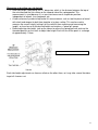
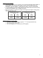
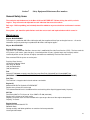
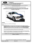
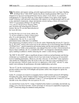
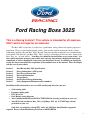
Ford Racing Boss 302S
This is a Racing Vehicle!! This vehicle is intended for off-road use
ONLY and is not legal for on-road use!
The Boss 302S is a turn-key, or in this case a push button, racing vehicle and requires proper race
preparation. Please read and understand the owner's guide and the detailed instructions for the various
components supplied with your Boss 302S. Beyond component specific maintenance we recommend that
you regularly "nut and bolt" your Boss 302S. This is a process of checking all the nuts, bolts, wiring, belts,
hoses, tires, etc…on your vehicle. Your Race Car should be checked before every session of use…it is
also equally important to inspect your vehicle after each use: this includes checking all mechanical
components as well as checking for codes using your Ford Pro-Cal tool. In addition you should also
review the data in your AIM data acquisition system outlined later in this manual. Please be diligent
with the care of your vehicle!
Section 1
Section 2
Section 3
Section 4
Section 5
Section 6
Section 7
Ford Racing Boss 302S Specifications
Driver Information / AIM system
Ford Pro-cal Instructions
Electrical Information
Torque Sheets
Brake/Chassis/Setup information
Safety Equipment/Maintenance/Part numbers
In addition to this manual there are several file on this jump drive for your use:
•
•
•
•
•
•
Sachs tuning guide
Dynamics tuning guide
DTC Error list
Ford Racing wiring diagrams
Aim Configuration File Boss302S FACTORYAIM.cfn (already preloaded on your car)
Aim GPS track coordinates Boss_302_S_GpsMngr_2011_06_13_174017.mpl (already
preloaded on your car)
Only after reviewing Pro-cal tool DTC codes and AIM data should further support be
required. Please call the Ford Racing Tech Line at 800-FORD788.
1
FORD RACING WARRANTY DISCLAIMER
FORD RACING PERFORMANCE PARTS AND VEHICLES ARE SOLD “AS IS”, “WITH ALL
FAULTS”, “AS THEY STAND” AND WITHOUT ANY EXPRESS WARRANTY WHATSOEVER. TO
THE FULLEST EXTENT ALLOWED BY THE STATE AND FEDERAL LAW, FORD MOTOR
COMPANY EXPRESSLY DISCLAIMS THE IMPLIED WARRANTIES OF MERCHANTABILITY AND
OF FITNESS FOR A PARTICULAR PURPOSE, EVEN IF A PARTICULAR PURPOSE IS
MENTIONED HEREIN. FORD ALSO EXPRESSLY DISCLAIMS ALL LIABILITY FOR DIRECT,
INDIRECT, SPECIAL, INCIDENTAL OR CONSEQUENTIAL DAMAGES, INCLUDING BUT NOT
LIMITED TO, DAMAGE OR LOSS OF PROPERTY OR EQUIPMENT, LOSS OF PROFITS OR
REVENUE, COST OF PURCHASE OR REPLACEMENT OF GOODS, OR CLAIMS OF
CUSTOMERS OF THE PURCHASER THAT RESULT FROM THE USE OF ANY AND ALL PARTS
OR VEHICLES CONTAINED IN THIS OWNER'S MANUAL. IN NO EVENT SHALL THE LIABILITY
OF FORD MOTOR COMPANY, WHETHER IN TORT, CONTRACT OR OTHERWISE, EXCEED THE
COST OF THE PART OR VEHICLE. HOWEVER, YOU MAY HAVE LEGAL RIGHTS WHICH VARY
FROM STATE TO STATE.
SHOULD ANY PARTS OR VEHICLES CONTAINED WITHIN THIS CATALOG PROVE DEFECTIVE
FOLLOWING THEIR PURCHASE, THE BUYER AND NOT THE MANUFACTURER, DISTRIBUTOR
OR RETAILER, SHALL ASSUME THE ENTIRE COST OF ALL NECESSARY SERVICING AND/OR
REPAIR. THE ENTIRE RISK AS TO THE PERFORMANCE OF SUCH PARTS OR VEHICLES IS
WITH THE BUYER.
THIS VEHICLE IS NOT STREET LEGAL OR CERTIFIED UNDER FEDERAL MOTOR VEHICLE
SAFETY STANDARDS AND REGULATIONS. THIS VEHICLE IS NEITHER INTENDED NOR
CERTIFIED FOR USE ON PUBLIC ROADS. MANY OF THE PARTS IN THIS OWNER'S MANUAL
ARE NOT DESIGNED OR TESTED FOR CRASHWORTHINESS OR TO MEET THE SAFETY
NEEDS OF THE MOTORING PUBLIC. INSTEAD, THESE PARTS ARE DESIGNED AND
INTENDED FOR RACE VEHICLES ON RACE TRACKS WITH ENGINEERS SUPERVISING THE
INSTALLATION AND USE OF THE RACE PARTS TO ENSURE THAT THE SAFETY NEEDS OF
THE RACE DRIVER ARE MET. THE RACING PARTS COULD CONCEIVABLY BE COMBINED IN
AN INFINITE COMBINATION, AND THE USE OF SOME PARTS ON SOME VEHICLES COULD
ADVERSELY AFFECT THE PERFORMANCE OF THE VEHICLE OR OTHER RACE PARTS.
TO THE EXTENT THAT A PART CONTAINED WITHIN THIS OWNER'S MANUAL COMES WITH A
WARRANTY FROM THE ORIGINAL MANUFACTURER, NOT FORD RACING PERFORMANCE
PARTS OR FORD MOTOR COMPANY, THE BUYER SHOULD CONTACT THE ORIGINAL
MANUFACTURER FOR ANY AND ALL WARRANTY REPAIR OR REPLACEMENT. TO
DETERMINE WHICH PARTS COME WITH A WARRANTY FROM THE ORIGINAL
MANUFACTURER, NOT FORD RACING PERFORMANCE PARTS, PLEASE CONTACT THE
FORD RACING PERFORMANCE CALL CENTER AT (800) 367-3788 OR:
FORD RACING PERFORMANCE PARTS
P.O. BOX 490
DEARBORN, MI 48121
2
Section 1
Ford Racing Boss 302S Specifications
Engine
5.0L Ford Racing Motorsport Engine, based on 2012 Mustang Boss 302 engine
Ford Racing Oil Pan, M-6675-M50BR
Ford Racing Oil Filter, CM-6731-FL820
Engine Oil: Motorcraft 5W50 full synthetic or equivalent
Setrab ProLine Engine oil cooler
Upgraded electrical connectors
FR intake badge
Boss 302 fuel system
Upgraded cooling system
Driveline
6 speed transmission with Dual Disc Clutch
Torsen T2R Diff
3.73 gears
Chassis
Front: coil over dampers
Front lower control arms with delrin bushing kit
FR adjustable front anti-roll bar
Caster/Camber plates
Rear: coil over dampers
Rear tubular lower control arms with spherical bearings
FR anti-roll bar FR adjustable panhard bar
EPAS with unique Ford Racing calibration
FIA Spec 6 point roll cage
FR1 Muffler
Electrical
Lightened FR wiring harness
AMB Transponder
Switch plate – Start/ignition, aux switches
Interior
AIM MXL data acquisition system with GPS
Recaro HANS Pro Racer seat
Fire system with 2 nozzles
Quick release racing steering wheel
Window net
Safety system triangle nets
6 point racing harness
Master cut off switch
Exterior
FR front splitter
Rear adjustable CF wing
Unique Carbon hood with air extractors
Hood pins
19X9″ and 19x10" wheels
Boss 302S graphics package
F/R tow hooks
Brakes
Brembo race 4 piston front brake system
2 piece 14″ front rotors
PFC racing pads
3
Carbon Fiber Brake duct kit
Stainless steel brake lines
FR brake booster assembly
Unique FR ABS calibration
Section 2
Driver Information/ AIM system
Your Boss 302S includes a MXL Pista which is a digital dash, gauge, and race data acquisition system featuring a tachometer, 8
analog inputs, 1 speed input, CAN/serial ECU connector, gear position indicator (From ECU), internal lateral G sensor, and lap
timer.
With standard features including a wide, fully configurable display, six configurable alarm LED’s, backlight, and USB connector,
the MXL is a stylish, powerful unit that re-defines the state of the art in data acquisition for performance vehicles.
It is very important that the AIM data is reviewed and retained….the software allows you to save information
such as date, driver and track. Also use the notes function after every download this will help you to recall
information at a later time.
The MXL Pista is interfaced with the Boss 302S PCM and allows you to monitor:
Lateral Acceleration: From the head unit's accelerometer (use this to compare setups, conditions or driving technique)
Battery Voltage: Recommended alarm for this channel is less than 13.5 Volts
P_RPM (Engine RPM): From the Boss PCM
P_ACT : Inlet air charge temperature
P_VSPD (Vehicle speed): Averaged vehicle speed
P_PEDAL: Throttle pedal position in percentage
P_GEAR: Manual transmission gear position
P_CMP_FAIL_FLAG: Normally zero…non-zero value indicates a camshaft error (see camshaft status codes)
P_EPOS_STATUS: Normally zero…non-zero value indicates a crankshaft position error
P_COIL_ERROR_FLG: Normally zero…non-zero value indicates a issue
P_HSF: 0=Cooling fan off 1= cooling fan on
P_FUELUSED: Fuel totalizer, when used with the Channel report the signal range will return Liters of fuel used per lap
A_WS_FL: The individual wheel speed of the Front Left wheel
A_WS_FR: The individual wheel speed of the Front Right wheel
A_WS_RL: The individual wheel speed of the Rear Left wheel
A_WS_RR: The individual wheel speed of the Rear Right wheel
P_CMP_STAT_I1: Normally 1, other values indicate camshaft issues on Bank #1 intake
P_CMP_STAT_E1: Normally 1, other values indicate camshaft issues on Bank #1 exhaust
4
P_CMP_STAT_I2: Normally 1, other values indicate camshaft issues on Bank #2 intake
P_CMP_STAT_E2: Normally 1, other values indicate camshaft issues on Bank #2 exhaust
P_LAMBDA_1: The air fuel ratio of bank #1 (a static value of 1 indicates a missing or problematic O2 sensors)
P_LAMBDA_2: The air fuel ratio of bank #2 (a static value of 1 indicates a missing or problematic O2 sensors)
The Boss 302S specific add-on hardware/channels are Oil Temp, Oil pressure and a GPS module.
The Oil pressure should not drop below 30 PSI during normal operating conditions (except hot idle). Oil Temperature should not
exceed 300 degrees Fahrenheit. The GPS module is included for lap timing without requiring a conventional beacon; it also
provides the following channels:
GPS_SPEED: Absolute vehicle speed (useful when comparing individual speed during abs events)
GPS_NSAT: Number of Satellites in range
GPS LAT_ACC: Calculated Lateral Acceleration
GPS LONG_ACC: Calculated Longitudinal Acceleration
Your AIM system will come preloaded with most tracks in North America….you can add additional tracks using GPSMANAGER
available on AIM's web site.
RPM 2-STEP / PIT LANE SPEED CONTROL (PLSC)
The Boss 302S has a RPM 2-STEP feature that will maintain a set engine speed while the accelerator pedal is
depressed. This feature is built into the powertrain control module (PCM) and does not require aftermarket
components.
1) RPM Indicator
When the ignition switch is turned "ON", the tachometer will momentarily display the current set point.
2)RPM Setting
The system utilizes a toggle switch in the center console to set the desired launch engine speed. Proper precautions
have been made to ensure the setting mode cannot be entered unless the vehicle is stopped. To set the 2-STEP RPM,
a simple 3 step process is required:
1. Depress the brake pedal with the engine running and simultaneously hold the toggle switch up for
approximately 2 seconds. The AIM tachometer will display the current 2 STEP set point. After the
tachometer sweeps and is displaying the current set point, release the toggle switch. The brake pedal can
also be released and is not necessary for the rest of the procedure.
5
2. The RPM point is adjusted by moving the toggle switch up or down. The RPM will change in 100 RPM
increments. The user range for the launch control is 2000 rpm to 7000 rpm and the PCM will not allow any
settings beyond these limits.
3. Once the desired launch control set point is achieved, press the "PLSC" button. The AIM tachometer will
again sweep to 8000 rpm, then back to the desired set point, and finally back to the current engine speed.
The system set point is now stored in the PCM's memory and will maintain this value until it is changed
again even if the power is removed from the PCM.
PIT LANE SPEED CONTROL (PLSC)
The Pit lane speed control is adjusted identically to the 2-STEP….however instead of holding the toggle switch
up…hold the toggle switch down to set the PLSC. The information will be displayed on the speed readout of the MXL.
After setting the desired speed once again store the setting by depressing the PLSC button on the steering wheel.
Section 3
Ford Pro-cal Instructions
Prepare ProCal II:
STEP 1: Remove the ProCal II from its plastic bag. Peel back the rubber boot from the lower portion of the
ProCal II to expose the MMC socket. Remove the MMC from its plastic case. Insert the MMC into the socket of the ProCal II
with the label of the MMC facing the same direction as the ProCal II display screen. Return the rubber boot
to its original position to cover the MMC.
STEP 2: Remove the J1962 cable from its plastic packaging. Insert the DB25 connector of the cable into the top of
the ProCal II. Finger-tighten the retaining screws of the DB25 so that it is firmly fastened to the ProCal II.
STEP 3: Make sure your vehicle’s battery is fully charged (at least 12.0 volts) and all accessories (radio, interior
fan, headlights, etc.) are off. If you are unsure if your vehicle’s battery is fully charged, connect a battery
charger prior to beginning the programming process.
CAUTION: If your ProCal II aborts programming due to low voltage or interrupted programming
process, you may be required to have the vehicle towed to an authorized Ford Dealer to
reprogram your PCM back to its original stock calibration.
STEP 4: Locate the onboard Diagnostic Link Connector (DLC) at the passenger side air vent.
STEP 5: Connect your OBDII connector of your ProCal II tool to the vehicle DLC.
Note: For the first time the ProCal II is plugged in, you may receive a message indicating BootLoader
firmware is updating. The RED error light will be on while the firmware is updating. This is normal for first
time power-up. Do not disconnect the ProCal II during this process once it has begun.
STEP 6: Turn the ignition key of your vehicle to the ON position….move to the diagnostic menu
6
Diagnostics Menu Structure:
Read DTC
Clear DTC
Select Protocol
Select Module
Other Tools
• Select Protocol
-HSCAN-ISO14229 (Boss 302S PCM & ABS)
• Select Module
-Select PCM
-Select ABS
• Read DTC(Diagnostic Trouble Codes)
-Once Module and Protocol are set will return PCM and ABS error codes.
• Clear DTC
-Once Module and Protocol are set will clear selected module codes.
• Other Tools
-KOEO-Key ON Engine OFF Diagnostic self test, warning fan will activate as part of self test
-KOER-Key ON Engine Running Diagnostic self test, you must press the brake and turn steering
wheel once during this test.
Section 4
Electrical Information
Additional information about the Boss Crate Motor harness used on the 302S can be found on the Ford Racing
website at http://www.fordracingparts.com/download/instructionsheets/FordInstShtM-6017-A504V_A54SC.pdf
OBDII Connector
Located on the passenger side air vent.
7
Controls Pack Power Distribution Box
The Controls Pack Power Distribution Box (PDB) is responsible for base engine electrical functions and is located
under the passenger side air bag cover. Fuse and relay locations in this PDB are indicated on the circuit board.
Refer to the circuit board picture below for clarification of fuse/relay locations in the Controls Pack PDB.
8
Vehicle Power Distribution Box
The Vehicle PDB shown in the following picture contains the fuses/relays used for headlights, taillights and other
vehicle functions. This PDB is located in the passenger side kick panel.
Fuse and relay locations for this PDB are shown below.
9
Relay
R1
R1
R1
R1
R2
R2
R2
R2
R4
R4
R4
R4
R5
R5
R5
R5
R8
R8
R8
R8
R12
R12
R12
R12
Pin
1
2
3
5
1
2
3
5
1
2
3
5
30
85
86
87
30
85
86
87A
30
85
86
87
Circuit #
300B
21B
22
20B
24A
26
23
20C
300C
25A
27A
20D
530
300D
201A
1600A
26
21C
300E
300H
1230
300J
1286C
555
To
C1200
C1200
C1200
S20
S24
R8
C1200
S20
C1200
S25
C1200
S20
F7
C1200
C1200
S1600
R2
C1200
C1200
C1200
F33
C1200
C1200
C1200
Pin
Description
35 Ground
14 High Beam Switch
6
High Beam Feed
12V HAAT 30A (F22)
Low Beam Coil
30 Low Beam Coil Ground
7
Low Beam Feed
12V HAAT 30A (F22)
36 Ground
Parking Lamps Coil
31 Parking Lamps Feed
12V HAAT 30A (F22)
2
12V HAAT 40A (F7)
37 Ground
16 Ignition On
R/S Feed to PDB
2
Low Beam Coil Ground
15 High Beam Switch
38 Ground
39 Ground
2
12V HAAT 30A (F33)
40 Ground
30 Intercooler Trigger
42 Intercooler Feed
Fuse
F3
F5
F7
F8
F9
F10
F13
F22
F25
F26
F29
F33
F34
F35
F39
F40
F46
F47
F48
Type
HAAT
HAAT
HAAT
HAAT
HAAT
HAAT
HAAT
HAAT
HAAT
HAAT
HAAT
HAAT
HAAT
HAAT
R/S
R/S
R/S
R/S
R/S
Source
BATT
BATT
BATT
BATT
BATT
BATT
BATT
BATT
BATT
BATT
BATT
BATT
BATT
BATT
S1600
S1600
S1600
S1600
S1600
Amps
20
20
40
40
30
30
15
30
20
10
30
30
30
10
10
10
15
15
10
Circuit #
200
80
530
110
70
120
270
20A
180A
220A
50
1230
40
230
250
260
140A
240A
170A
To
C1200
C1200
R5
C1200
C1200
C1200
C1200
S20
C1200
C1200
C1200
R12
C1200
C1200
C1200
C1200
C1200
S240
S170
Pin
3
5
30
9
34
1
13
25
26
29
30
8
17
20
24
4
Description
T1 - 12V HAAT
Power Point / Line Lock
12V to 'Key-On Power' Fuses
ABS Power
Wiper Motor
ABS Power
Mirrors
Headlamps
Brake Lamps / Flashers / Turn
Cluster / Light Switch Feed
Power Window Motor LT
Intercooler Pump
Power Window Motor RT
T4 - Aux 1
T5 - Aux 2
T6 - Aux 3
Window Switch
RCM/ABS/SPS Feed
Cluster/Wiper/MFS Feed
Splice
S20
S20
S20
S20
S24
S24
S24
S25
S25
S25
S1600
S1600
S1600
S1600
S1600
S1600
S240
S240
S240
S170
S170
S170
Circuit #
20A
20B
20C
20D
24A
24B
24C
25A
25B
25C
1600A
1600B
1600C
1600D
1600E
1600F
240A
240B
240C
170A
170B
170C
To
F22
R1
R2
R4
R2
D1
C1200
R4
D1
C1200
R5
F39
F40
F46
F47
F48
F47
C1200
C1200
F48
C1200
C1200
Pin
2
5
5
5
1
1
2
2
2
11
87
1
1
1
1
1
2
22
23
2
18
19
Description
12V HAAT 30A (F22)
High Beam Feed
Low Beam Feed
Parking Lamps Feed
Low Beam Coil
Diode to Parking Lamps
Low Beam Signal
Parking Lamps Coil
Diode from Low Beam
Parking Lamps Signal
R/S Power Feed
R/S Power Feed
R/S Power Feed
R/S Power Feed
R/S Power Feed
R/S Power Feed
12V R/S 15A (F47)
12V R/S 15A (F47)
12V R/S 15A (F47)
12V R/S 10A (F48)
12V R/S 10A (F48)
12V R/S 10A (F48)
Future Expansion
Three fused 10Amp circuits are available on the center console for addition of customer accessories such as data
loggers, radios, etc. These circuits can be accessed by removing the center console and adding the circuit to the
output side of the desired switch. One of the circuits uses 12V Hot At All Times (HAAT) power while the other two
circuits interface to Run/Start (R/S) Power and will only provide power when the ignition switch is in the ON position.
Please find the individual wiring diagrams on the FR thumb drive.
10
Section 5
Torque Sheets
Bolt Torque Spec. Sheet
Location:
Engine Mount to Crossmember
Engine Mount to Engine Block Bracket
Engine Block Bracket to Engine Block
Flywheel to Crank
Pressure Plate to Flywheel
Transmission Bellhousing to Engine
Starter Motor to Transmission Bellhousing
Transmission Mount to Transmission
Transmission Mount to Body
Transmission Lever to Transmission
Shift Lever Mount to Body
Driveshaft to Transmission
Driveshaft Mid-Bearing to Body
Driveshaft to Rear Axle
H-Pipe Flange to Manifold
H-Pipe to Tail Pipe Clamp
Tailpipe to Muffler Clamp
Steering Rack to Crossmember
Jam Nut, Outer to Inner Tie Rod
Outer Tie Rod to Spindle
Caliper Bracket to Spindle
Caliper to Caliper Bracket (Front)
Spindle to Coilover
Coilover to Camber Plate
Camber Plate to Body
Wheel Hub to Spindle
Lower Control Arm to Crossmember PT3 (Front)
Lower Control Arm to Crossmember PT4 (Front)
Lower Control Arm to Spindle PT6
Sway Bar Link to Coilover
Sway Bar Link to Sway Bar
Sway Bar Mount to Crossmember
Crossmember to Body
Pencil Brace to Crossmember
Drop Bracket to Axle
Drop Bracket to Coilover
Coilover to Top Clevis Bracket
Top Clevis Bracket to Body
Axle to 3rd Link
3rd Link to Body Bracket
3rd Link Body Bracket to Body Forward
3rd Link Body Bracket to Body Rearward
Cailper to Axle (Rear)
ABS Sensor to Hub
Lug Nut
Type of Fastener
Torque in Nm
Torque in Ft Lbs
Bolt
Nut
Bolt
Bolt
Bolt
Bolt
Bolt
Bolt
Bolt
Bolt
Nut
Bolt
Bolt
Bolt
Bolt & Nut
Nut
Nut
Bolt
Nut
Nut
Bolt
Stud
Bolt
Nut
Bolt & Nut
Nut
Bolt
Bolt & Nut
Bolt & Nut
Nut
Nut
Nut
Bolt & Nut
Nut
Bolt & Nut
Bolt & Nut
Bolt & Nut
Nut
Bolt & Nut
Bolt & Nut
Bolt
Bolt
Bolt
Bolt
Nut
55.0
62.5
55.0
20.0 + 60 degrees
62.5 + 60 degrees
47.5
25.0
47.5
62.5
40.0
10.5
109.0
47.5
55.0
40.0
47.5
30.0
115.0
55.0
80.0
115.0
47.5
225.0
103.0
35.0
340.0
210.0
185.0
103.0
115.0
115.0
70.0
115.0
47.5
115.0
115.0
115.0
40.0
175.0
175.0
440.0
115.0
103.0
15.0
135.0
40.5
46.1
40.5
10 + 60 degrees
46.1 + 60 degrees
35.0
18.0
35.0
46.1
29.5
7.8
80.4
35.0
40.5
29.5
35.0
22.1
84.8
40.5
59.0
84.8
35.0
165.9
75.9
25.8
251.0
154.8
136.4
75.9
84.8
84.8
51.6
84.8
35.0
84.8
84.8
84.8
29.5
129.0
129.0
325.0
85.0
75.9
11.0
100.0
11
Section 6
Brake/Chassis/Setup information
Brakes
Your Boss 302S comes equipped with Brembo road race brakes, a Ford Racing brake booster, PFC racing pads and a
TRW Race ABS system that is uniquely tuned to the car. Changing any of these components from the intended
design will degrade brake system performance. This could result in increased stopping distances or degraded pedal
feel.
Dampers
The base 2-way dampers are manufactured by SACH. These were originally used on the FR500S and were retuned
for the Boss 302S.
The Optional 3 way dampers are Dynamics manufactured by Multimatic, these are uniquely tuned to the Boss 302S..
These are serviced by:
Carl Haas Automobile Imports, Inc
Contact Alan O'Leary
500 Tower Parkway
Lincolnshire, IL 60069
Phone: (847) 634-8200
Fax: (847) 634-8208
Both the Sachs and Dynamics tuning guides are on this FR thumb drive.
Chassis Setup Specifications and Procedures
The following setup specifications and procedures are recommended starting points for the BOSS
302S. Optimal ride height and alignment will vary by track.
Preparing the vehicle for setup:
• Fill the vehicle with fuel. The saddle type fuel tank in this vehicle does not maintain even
fuel levels between the two sides, so the only way to ensure consistent left/right balance
and setup is to fill the tank.
• Make sure that the vehicle is setup in as-raced conditions, with all extra equipment and
ballast installed.
• Install an unused (or clean, lightly used) set of tires if possible; the variation in diameter and
stuck-on rubber bits typical of used tires can affect corner weights. Set tire pressures to
30psi, or another nominal setting that is the same on both axles.
• Ballast the driver's seat to simulate the driver's weight, or use the actual driver (if you have a
very patient driver with nothing better to do)
• Optional - setting the shocks to full soft in compression and rebound will help the car to
settle more consistently and will result in a more accurate setup.
• Make sure that the vehicle has been rolled forward in a straight line and bounced up and
down to settle the suspension before making any measurements.
12
•
Changes to ride heights, corner weights, and alignment will have effects on each other.
Getting these settings correct is an iterative process. If you are making a major change or a
new installation/re-installation, make a rough setup of height and alignment before starting
with fine adjustments
Measuring and setting front ride height:
• Front ride height is defined by the "C" dimension, which is the difference in height between
the inner pivot of the front lower control arm and the bottom of the balljoint can. This
measurement is used because it is a consistent measure of suspension position,
independent of wheels, tires, bodywork, etc.
• Measuring the height of the center of the balljoint can be difficult because it is inside the
wheel. One method is to use a dial indicator base with a pointer, setting the base on a
ground reference and setting the pointer on the center of the can; with the pointer locked in,
remove the base/pointer and set it on a flat surface and measure the height. This
measurement is independent of ride height, and will not change as long as the same
wheel/tire/pressure is used, so it only needs to be measured once per setup session.
• The inner pivot height can be measured with a tape measure from the ground to the center
of the bolt.
• Before adjusting ride height, jack up the corner to relieve the spring pressure and use the
threaded perches on the struts to adjust ride height. Each full turn of the perch is a change
of approximately 1.5mm.
Front "C" Dimension = 11mm
(Inner pivot higher than balljoint)
13
Measuring and setting rear ride height:
• Rear ride height is defined by the "D" dimension, which is the distance between the top of
the axle tube and the flat surface on the inboard side of the spring pocket. This
measurement is used because it is a consistent measure of suspension position,
independent of wheels, tires, bodywork, etc.
• A tool can be easily made to help make this measurement, such as two flat pieces of metal
with a bolt and wingnut to lock them together at a given setting. This can be used to
measure the current height (setting it on the vehicle, then removing and measuring the
length), or it can be set to the desired height and used as a "go/no-go" gauge.
• Before adjusting ride height, jack up the corner to relieve the spring pressure and use the
threaded perches on the struts to adjust ride height. Each full turn of the perch is a change
of approximately 1.5mm.
Rear "D" Dimension = 90mm
Each ride height adjustment can have an effect on the other three, so it may take several iterations
to get all 4 corners set.
14
Adjusting corner weights:
• Once initial ride heights are set, use corner scales to measure and adjust corner weights so
that the diagonal (RF+LR and LF+RR) weights are 50% (OR AS CLOSE TO 50% AS
POSSIBLE). The "Cross Weight %" (shown on many scales) is the RF+LR Percentage
• It is recommended that all corner weight adjustments be made at the rear of the car, raising
or lowering the appropriate side as needed. (See chart)
• Note that the process of setting corner weights will change the ride heights and they will no
longer be equal side-to-side.
To RAISE Cross Weight %
(RF+LR)
LF
RF
LOWER
RAISE
LR
RAISE
RR
LOWER
To LOWER Cross Weight %
(RF+LR)
LF
RF
RAISE
LOWER
LR
LOWER
RR
RAISE
Adjusting alignment (In this order):
• Set caster. Recommended setting is typically 7° - 7.5°, but equal on both sides;
• Set Camber on both sides to -3.0°
• Set Toe to 0 degrees or 1/8" total toe out on 30" toe plates
15
Section 7
Safety Equipment/Maintenance/Part numbers
General Safety items
The seat belts and window nets in the Boss 302S are NOT PRE SET. Before driving the vehicle, set belt
lengths. They will need to be adjusted for each individual that races this vehicle.
Roll cage – Roll bar padding (not included) should be added to any areas the driver could come in contact
with.
Fire system – pin should be pulled before each time out on track and replaced when vehicle comes in.
Maintenance
Engine: M-6007-M50BR
The engine is a production 2012 Boss 302 engine with the exception of the oil pan and engine harness…all service
information and parts pertaining to a production 2012 Boss 302 engine applies.
Oil pan: M-6675-M50BR
Engine Wiring harness
This harness is a production 5.0L Boss harness that is modified by Precision Race Services (PRS). The four camshaft
VCT phasers (cam covers, front of engine), 4 camshaft position sensors (cylinder head, rear of engine) and the
crankshaft position sensor (RH rear of engine) connection are modified by Precision Race Services.
Please contact PRS for spares or service parts:
Precision Race Services
16749 Dixie Highway Suite 9
Davisburg, MI 48350
(248) 634-4010 office
(248) 634-4014 fax
Fuel
Sunoco GT 260 www.sunocoinc.com/Site/Consumer/RaceFuels/UnleadedFuels/Sunoco260GT.htm
(WARNING! USING A LOWER OCTANE FUEL WILL CAUSE PERMANENT DAMAGE TO THE ENGINE)
Fuel Filter
The Fuel filter is integral to the fuel tank and non-serviceable.
Engine Oil
Motorcraft 5W-50 Full Synthetic XO-5W50-QGT
Replace every 4 hours on-track usage
The recommended oil level is the bottom of the crosshatching of the dipstick (approximately 14 quarts)
Oil Filter
Ford Racing M-6731-FL1A (case of 12) or CM6731-FL820 (individual)
Replace every 4 hours of on-track usage
Regularly check the catch can for oil located on the passenger side rear of the engine compartment.
Capacity: 13 Quarts
Engine Coolant
Motorcraft Premium Gold VC-7B
50/50 Mix Ratio
Change annually and follow guidelines on container for freeze protection
Use only distilled water!
16
Transmission Fluid
XT-2-QDX Mercon ATF
Replace every 4 hours on-track usage
Capacity: 3.46L
Clutch: CR3V-7B546-AA 2012 GT500 Dual Disc
Note refer to factory service manual when servicing.
Differential Oil
75W140 Synthetic Gear Lube Motorcraft XY-75W140-QL
Replace every 4 hours on-track usage
Capacity: Fill to bottom of filler hole.
Brake Fluid
Use only High Performance DOT3 PM-1-C
Bleed brakes after each session. Replace Fluid after each event
Wheel/Tires
Front; Pirelli P Zero 255/40ZR19
Rear; Pirelli P Zero 285/35ZR19
Wheel torque: 95 ft-lbs
For World Challenge competition the following wheel and tires are required….
Wheels 18x10" Ford Racing M-1007-R1810 (requires unique lug nuts)
Part
Allstar-ALL44102
Number:
Product
Photo:
Description:
LUG NUTS 1/2-20
STEEL 10PK
Tires: Pirelli 305/645-18 P Zero Race Slick
Air Filter
FA1897-Motorcraft
Replace after every 12 hours of usage
Spark Plugs
BR3E-12405-DA (Heat Range 1) or M-12405-M50 (Heat range 0)
SP519-Motorcraft
GAP= 0.04 (1.0 mm)
Replace after every 6 hours of usage
Fuel Pressure,
55±2 psi gauge, fuel pump on and engine off
17
Part number listing
Part description
Part number
Button, Start Engine
M-11572-GT
Shock Mount, Rear
M-18197-A
Booster, Race Brake
M-2005-R
Pad, Rear Brake Kit
M-2200-R
Differential
Kit, Ring & Pinion Install
Crossbrace, Trans Cooler Air Scoop
Muffler, SVT Kit
M-4204-T31H
M-4210-B1
M-5025-MBR
M-5230-MGTCA1
Bar, Front Anti Roll
M-5490-A
Bar, Rear Anti Roll
M-5490-A
Adaptor, Remote Oil Filter (On Engine Block)
M-6881-M50
Shifter Assembly
M-7210-B
Lever, Shift
M-7213-J
Radiator Assembly
M-8005-MGT
GT500 Transmission
AR3V-7003-BC
18