1
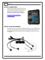
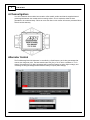
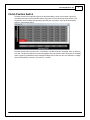
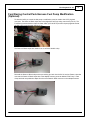
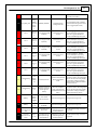
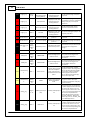
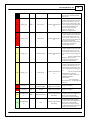
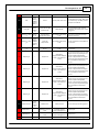
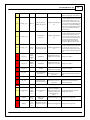
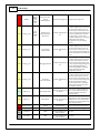
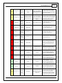
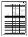
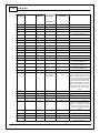
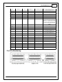
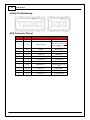
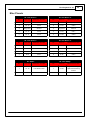
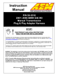
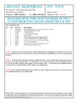
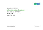
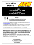
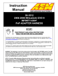
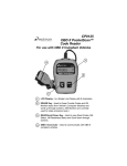
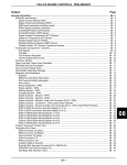
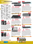
Instruction
Manual
P/N 30-3812
Ford Coyote 5.0L V8
with Ford Racing Controls Pack
Plug & Play Adapter Harness
STOP!
THIS PRODUCT HAS LEGAL RESTRICTIONS.
READ THIS BEFORE INSTALLING/USING!
THIS PRODUCT MAY BE USED SOLELY ON VEHICLES USED IN SANCTIONED COMPETITION WHICH MAY NEVER BE USED UPON A
PUBLIC ROAD OR HIGHWAY, UNLESS PERMITTED BY SPECIFIC REGULATORY EXEMPTION. (VISIT THE “EMISSIONS” PAGE AT HTTP://
WWW.SEMASAN.COM/EMISSIONS FOR STATE BY STATE DETAILS.)
IT IS THE RESPONSIBILITY OF THE INSTALLER AND/OR USER OF THIS PRODUCT TO ENSURE THAT IT IS USED IN COMPLIANCE WITH
ALL APPLICABLE LAWS AND REGULATIONS. IF THIS PRODUCT WAS PURCHASED IN ERROR, DO NOT INSTALL AND/OR USE IT. THE
PURCHASER MUST ARRANGE TO RETURN THE PRODUCT FOR A FULL REFUND.
THIS POLICY ONLY APPLIES TO INSTALLERS AND/OR USERS WHO ARE LOCATED IN THE UNITED STATES; HOWEVER CUSTOMERS
WHO RESIDE IN OTHER COUNTRIES SHOULD ACT IN ACCORDANCE WITH THEIR LOCAL LAWS AND REGULATIONS.
WARNING: This installation is not for the tuning novice! Use this system with EXTREME caution! The AEM
Infinity Programmable EMS allows for total flexibility in engine tuning. Misuse or improper tuning of this
product can destroy your engine! If you are not well versed in engine dynamics and the tuning of engine
management systems DO NOT attempt the installation. Refer the installation to an AEM-trained tuning
shop or call 800-423-0046 for technical assistance.
NOTE: All supplied AEM calibrations, Wizards and other tuning information are offered as potential
starting points only. IT IS THE RESPONSIBILITY OF THE ENGINE TUNER TO ULTIMATELY CONFIRM IF THE
CALIBRATION IS SAFE FOR ITS INTENDED USE. AEM holds no responsibility for any engine damage that
results from the misuse or mistuning of this product!
AEM Performance Electronics
AEM Performance Electronics, 2205 126th Street Unit A, Hawthorne, CA 90250
Phone: (310) 484-2322 Fax: (310) 484-0152
http://www.aemelectronics.com
Instruction Part Number: 10-3812
Document Build 7/31/2015
2
P/N 30-3812
OVERVIEW
The 30-3812 AEM Infinity Adapter Kit was designed to interface the Ford Coyote 5.0L Engine wiring
harness and the Ford Racing Control Pack – 5.0L 4V TI-VCT Manual Transmission. This is a true
standalone system that eliminates the use of the Ford Racing ECU. The use of this adapter makes the
kit “plug and play” so no cutting or splicing wires is necessary. The base configuration files available for
the Infinity EMS are starting points only and will need to be modified for every specific application.
The available Infinity EMS part numbers for this adapter kit are:
30-7101 INFINITY-8
30-7100 INFINITY-10
Please read this document in its entirety before attempting to start or run an engine.
GETTING STARTED
Refer to the 10-7100 for EMS 30-7100 Infinity Quick Start Guide for additional information on getting
the engine started with the Infinity EMS. The Ford Coyote V8 base session is located in C:\Documents
\AEM\Infinity Tuner\Sessions\Base Sessions.
Application
Ford Racing 5.0L 4V TI-VCT Mustang Crate Engine Ford Racing P/N M-6007-M50
Ford Racing Controls Pack – 5.0L 4V TI-VCT Manual Transmission Ford Racing P/N M-6017-A504V
Important Application Notes
Before installing the 30-3812 Adapter Kit it is suggested to completely install the Ford Racing Control
Pack as per the Ford Racing supplied instructions.
The Infinity Adapter Harness included in the 30-3812 kit includes Intake Air Temperature (Infinity C1-67)
wired to both the AUX connector and the Ford Racing MAF connector. Only one of these signals can be
connected to the Infinity at a time. If the AUX connector input is used either de-pin or disconnect the
Ford Racing MAF signal wire or connector.
The coils used for testing were factory two-wire ignition coils (Motorcraft P/N BR3Z-12029-A). This
adapter harness kit includes two AEM 4 Channel Coil Drivers (AEM P/N 30-2840) required to drive these
coils.
The Ford Racing Controls Pack wiring harness includes connectors for factory LSU 4.9 Wideband
Oxygen sensors, which the Infinity EMS does not currently support. Included with this kit are two LSU
4.9 to LSU 4.2 adapter harnesses. These harnesses allow the existing Ford Racing harness to interface
with AEM LSU 4.2 Wideband Oxygen sensors (p/n 30-2001, sold separately) to be controlled by the
Infinity EMS.
The Ford Racing Control Pack powers the fuel pump relay any time 12v is supplied to the ‘Ignition Switch
Position’ wire. A modification can be made to the Ford Racing wiring harness to allow the Infinity EMS to
control the fuel pump and is provided in the "Fuel Pump Modification" section of this document.
The Ford Racing Controls Pack includes a Power Distribution Box containing relays for A/C, PCM,
Intercooler, Fuel Pump, Start, and Fan. With the fuel pump relay modification mention above, the Infinity
EMS will control all of these relays with the exception of the A/C relay, which is not wired into the Ford
Racing harness.
© 2015 AEM Performance Electronics
Ford Coyote 5.0L V8
3
The base configuration file provided for the Coyote application was created with the use of the Ford
Racing Mustang Boss 302 Alternator Kit (P/N M-8600-M50BALT). The calibration has Lowside 0 duty
and frequency tables setup to charge at ~14.7 volts. See "Alternator Control" section for more
information on controlling the charging system.
The base calibration provided was created without the use of the Ford Racing Controls Pack air box, inlet
tube, or MAF sensor. The Factory MAF sensor is not currently supported by the Infinity EMS for airflow
calculations; however the Air Temperature sensor within the MAF has been characterized and may be
utilized.
The Infinity EMS requires a MAP sensor for airflow calculations. A custom adapter was fabricated to
replace the PCV inlet pipe into the passenger side of the throttle body assembly. A vacuum line from this
adapter to a MAP sensor was utilized. The MAP sensor will need to be wired into the proved 12-pin AUX
plug.
The base calibration utilizes the Clutch Position (Neutral Switch) flying lead on the Ford Racing wiring
harness as an input into the Infinity EMS. Once grounded, the Infinity EMS provides the ground for the
Starter Relay control circuit. If the user wishes not to provide a ground to this flying lead, follow the steps
provided in the "Clutch Position Switch" section to modify the LS8_Duty [%] table values to allow the
starter to be engaged without a clutch signal.
The factory Cylinder Head Temperature sensor, Intake Air Temperature sensor, and fuel injector have
been fully characterized and their calibrations are utilized in the base calibration.
DOWNLOADABLE FILES
Files can be downloaded from www.aeminfinity.com. An experienced tuner must be available to configure
and manipulate the data before driving can commence. The Quick Start Guide and Full Manual describe
the steps for logging in and registering at www.aeminfinity.com. These documents are available for
download here: http://w w w .aemelectronics.com/products/support
Kit Contents
AEM P/N
36-3812
36-3812-00
35-2840
4-1009
4-1010
4-1008
1062-20-0122
35-3014
10-3812
Description
Harness, Infinity Coyote Adapter
Harness, UEGO LSU4.2 to LSU4.9 Adapter
Ignitor, 4-Channel with Thermal Paste
Dust Cap, Flash Enable and Fuel Pump
Jumper, Flash Enable
Connector, DTM06-12SA Plugged
Socket, DTM Size 20
Cable, USB Comms 9.8'
Instruction Sheet, 30-3812
Qty
1
2
2
2
1
1
14
1
1
OPTIONS
30-2001 UEGO Wideband O2 Sensor
Bosch LSU4.2 Wideband O2 Sensor that connects to AEM 30-3600 UEGO Wideband O2 Sensor
Extension Harness
30-3602 IP67 Logging Cable
USB A-to-A extension cable: 39” long with right angled connector and bayonet style lock
© 2015 AEM Performance Electronics
4
P/N 30-3812
INFINITY CONNECTORS
The AEM Infinity EMS uses the MX123 Sealed Connection
System from Molex. AEM strongly recommends that users
become familiar with the proper tools and procedures for
working with these high density connectors before
attempting any modifications. The entire Molex MX123
User Manual can be downloaded direct from Molex at:
http://www.molex.com/mx_upload/family//
MX123UserManual.pdf
INFINITY ADAPTER HARNESS
Included with the Ford Coyote 5.0L PNP to Ford Racing Control Pack kit is an Infinity adapter harness.
This is used to make the connection between the AEM Infinity EMS and both the Ford Engine harness
and Ford Racing Control Pack harness plug and play. This is depicted below with the two Infinity
connectors and the Ford header. There are also a few other integrated connectors within this harness
described below.
© 2015 AEM Performance Electronics
Ford Coyote 5.0L V8
5
There are two AEM 4 Channel Coil Drivers included with this kit. Each must be connected to the adapter
harness with one 4P and one 5P connector. Ensure that the 4P and 5P connectors marked “Coil 1”
connect to opposite ends of the same 4 Channel Coil Driver. Similarly, the 4P and 5P connectors
marked “Coil 2” should also be connected to opposite ends of the second AEM 4 Channel Coil Driver.
The grey Deutsch 2P DTM “Flash” connector is used for secondary hardware flashing. The included
shunt connector jumps the 2 wires together. Once initially flashed, the EMS is normally upgraded in the
software, not requiring this connector.
The grey Deutsch 2P DTM “Fuel Pump” connector is used for an optional user modification discussed in
the "Fuel Pump Modification" section allowing the Infinity EMS to control the Ford Racing harness Fuel
Pump relay.
The grey Deutsch 12P DTM “AUX” connector is used to adapt many common ancillary inputs and
outputs easily. Included in the kit are a DTM 12P mating connector, 12 DTM terminals, and a DTM 12P
wedgelock. If used, these components will need to be terminated by the installer or end user with 1622awg wire (not included). Note: the pin numbering is molded into the connector, as shown. See Page
28 for pinout.
WIDEBAND/UEGO SENSOR ADAPTER HARNESS
Included with the AEM Infinity EMS PNP adapter harness kit are two LSU4.9 to LSU4.2 adapter
harnesses. These are used to make the connection between the Ford Racing Control Pack harness and
LSU4.2 Wideband 02 sensors (AEM P/N 30-2001).
NOTE: The AEM Infinity EMS is compatible ONLY with Bosch LSU4.2 sensors. These adapters are
supplied to ease installation and minimize the need to modify wiring. An AEM Infinity EMS should never
be plugged in and turned on with Bosch LSU4.9 (original Ford Coyote sensors) connected. It is
imperative that the original Ford O2 sensors are unplugged from the wiring harness before connecting the
AEM Infinity EMS.
© 2015 AEM Performance Electronics
6
P/N 30-3812
4-Channel Ignitors
It is critical that this driver module be mounted to a flat metallic surface and that the supplied thermal
grease applied between the module and its mounting surface. This is required to allow the heat
generated to be conducted away. Failure to mount the driver in this manner will cause a premature failure
and will void the warranty.
Alternator Control
The Ford Mustang Boss 302 Alternator is controlled by a fixed frequency and a duty percentage that
controls the charge set point. The base session sets LS0_Duty to 35 % which correlates to ~14.7v
charge. Decreasing the LS0_Duty percentage will increase the battery set point (higher voltage), and
increasing the duty percentage will decrease the battery set point (lower voltage).
© 2015 AEM Performance Electronics
Ford Coyote 5.0L V8
7
Clutch Position Switch
The base session will not provide a ground for the Starter Relay control circuit unless a ground is
provided to the Clutch Position (Neutral Switch) flying lead on the Ford Racing wiring harness. This
requirement can be modified through setting the LS8_Duty [%] table to 100% at all ClutchSwitch
positions. See example below:
The base session sets the input for the ‘ClutchSwitch’ 1D table channel to Analog20, which is pulled up
to 5 volts. The pinout provided in this manual suggests wiring the Clutch Position flying lead to Analog20.
When a ground is provided this drops Analog20’s voltage from 5 volts to 0 volts, this transition in voltage
sets the ClutchSwitch channel to 0 (5 volts) or 1 (0 volts).
© 2015 AEM Performance Electronics
8
P/N 30-3812
Drive By Wire
The base calibration will set most of the Drive-By-Wire (DBW) channels for the stock 5.0L Coyote throttle
body. If a different throttle body is used, Supra Cobra or Cobra Jet, then further adjustments to the DBW
channels may be required. To complete the DBW setup the Drive By Wire Wizard must be ran.
Select Calibrate sensor data only and follow the DBW Setup steps.
Note: There are a few integrated DBW fail safes incorporated into the Infinity system. For instance, if the
accelerator pedal and throttle position sensors do not track each other, or if the maximum DBW current
is exceeded, there will be a fatal error which will kill the engine for safety purposes. This error will reset
when the ignition key is turned off momentarily, and then turned back on.
Variable Valve Control (VVC)
The AEM Infinity system supports Fords Coyote’s Variable Valve Control. The base calibration is
configured with base VVC settings that may need adjustment.
For proper VVC function, the user must sync the cam timing by following the instructions listed in Setup
Wizard: Wizards>Setup Wizard>VVC>VVC Cam Sync. Once the cam sync has been verified for all four
cams, variable valve control may be enabled by checking the boxes next to each camshaft in the VVC
Enable section of the Wizard.
© 2015 AEM Performance Electronics
Ford Coyote 5.0L V8
9
Ford Racing Control Pack Harness Fuel Pump Modification
(Optional):
To allow the Infinity to control the fuel pump a modification must be made to the C47 flying lead
connector. The Green w/ Black stripe wire is the Highside Fuel Pump relay control wire (C47-01). The
Ford Racing harness double crimps 12v Start & Run (C47-03 ISP-R) to this fuel pump highside so that
the fuel pump is running when the key is on.
The Green w/ Black stripe wire needs to be cut off of this double crimp.
Reinstall the Green w/ Black stripe wire’s pre-existing pin back into the C47-01 socket. Route a wire that
connects the Green w/ Black stripe wire to the adapter harness connector labeled “Fuel Pump”. Extra
crimp terminals are provided to adapt this wire to the Deutsch DTM connector on the adapter harness.
© 2015 AEM Performance Electronics
10
P/N 30-3812
PINOUTS
Infinity Pinout
Infinity
Pin
Infinity
Assignment
C1-1
LowsideSwitch_
4
Dedicated
Dedicated and not reconfigurable
Assigned
Assigned but reconfigurable
Available
Available for user setup
Not Applicable
Not used in this configuration
Required
Required for proper function
Pin
Destinati
on
Ford Coyote with FR
Control Pack
Description
Infinity Hardware
Specification
Ford
Racing
PCM70 51
Intercooler Pump
Relay Control (SCICP
PCM signal)
Lowside switch, 4A max,
NO internal flyback
diode.
'See Setup Wizard Page "LowSide
Assignment Tables" for configuration
options. See 2D table "LS4_Duty [%]"
for activation settings.
Engine
E - 16
Variable Camshaft
Timing 21 Solenoid
(Driverside Intake)
Lowside switch, 4A max
with internal flyback
diode. Inductive load
should NOT have full time
power.
'See Setup Wizard Page "LowSide
Assignment Tables" for configuration
options. See 2D table "LS5_Duty [%]"
for activation settings. See Setup
Wizard page 'VVC' for options.
LowsideSwitch_
6
Engine
E - 56
Variable Camshaft
Timing 12 Solenoid
(Passengerside
Exhaust)
Lowside switch, 4A max
with internal flyback
diode. Inductive load
should NOT have full time
power.
'See Setup Wizard Page "LowSide
Assignment Tables" for configuration
options. See 2D table "LS6_Duty [%]"
for activation settings. See Setup
Wizard page 'VVC' for options.
C1-4
UEGO 1 Heat
Ford
Racing
PCM50 24
UEGO 1 Heat
Bosch UEGO controller
Lowside switch for UEGO heater
control. Connect to pin 4 of Bosch
UEGO sensor. NOTE that pin 3 of the
Sensor is heater (+) and must be
power by a fused/switched 12V
supply.
C1-5
UEGO 1 IA
Ford
Racing
PCM50 29
UEGO 1 IA
Trim Current signal. Connect to pin 2
of Bosch UEGO sensor
C1-6
UEGO 1 IP
Ford
Racing
PCM50 17
UEGO 1 IP
Pumping Current signal. Connect to
pin 6 of Bosch UEGO sensor
C1-7
UEGO 1 UN
Ford
Racing
PCM50 - 4
UEGO 1 UN
Nernst Voltage signal. Connect to
pin 1 of Bosch UEGO sensor
UEGO 1 VM
Ford
Racing
PCM50 15
UEGO 1 VM
Virtual Ground signal. Connect to pin
5 of Bosch UEGO sensor.
Flash_Enable
2P "Flash
Enable" 2
C1-2
C1-3
C1-8
C1-9
LowsideSwitch_
5
Flash Enable
10K pulldown
Notes
Not usually needed for automatic
firmware updates through Infinity
Tuner. If connection errors occur
during update, connect 12 volts to
this pin before proceeding with
© 2015 AEM Performance Electronics
Ford Coyote 5.0L V8
11
upgrade. Disconnect the 12 volts
signal after the update.
C1-10
+12V_R8C_CPU
Ford
Racing
PCM70 62 and 2P
"Flash
Enable" 1
KAPWR / 12VHAAT
Dedicated power
management CPU
Full time battery power. MUST be
powered before the ignition switch
input is triggered (See C1-65).
25 mA max source
current
0-5V Falling edge fire. DO NOT
connect directly to coil primary.
Must use an ignitor OR CDI that
accepts a FALLING edge fire signal.
C1-11
Coil 4
5P "Coil
Coil on Plug Assembly
Driver 1" 4 (COP-D)
5
C1-12
Coil 3
5P "Coil
Coil on Plug Assembly
Driver 1" 3 (COP3F)
4
25 mA max source
current
0-5V Falling edge fire. DO NOT
connect directly to coil primary.
Must use an ignitor OR CDI that
accepts a FALLING edge fire signal.
Coil 2
5P "Coil
Coil on Plug Assembly
Driver 1" 2 (COP2H)
2
25 mA max source
current
0-5V Falling edge fire. DO NOT
connect directly to coil primary.
Must use an ignitor OR CDI that
accepts a FALLING edge fire signal.
Coil 1
5P "Coil
Coil on Plug Assembly
Driver 1" 1 (COP1A)
1
25 mA max source
current
0-5V Falling edge fire. DO NOT
connect directly to coil primary.
Must use an ignitor OR CDI that
accepts a FALLING edge fire signal.
C1-15
Coil 6
5P "Coil
Coil on Plug Assembly
Driver 2" 6 (COP6E)
2
25 mA max source
current
0-5V Falling edge fire. DO NOT
connect directly to coil primary.
Must use an ignitor OR CDI that
accepts a FALLING edge fire signal.
C1-16
Coil 5
5P "Coil
Coil on Plug Assembly
Driver 2" 5 (COP5B)
1
25 mA max source
current
0-5V Falling edge fire. DO NOT
connect directly to coil primary.
Must use an ignitor OR CDI that
accepts a FALLING edge fire signal.
C1-13
C1-14
Ford
Racing
PCM70 18
Fan Relay Control
Lowside switch, 4A max,
NO internal flyback
diode.
See Setup Wizard Page "LowSide
Assignment Tables" for configuration
options. See 2D table "LS5_Duty [%]"
for activation settings. See Setup
Wizard page 'User GPOs' for default
activation criteria.
LowsideSwitch_
3
Engine
E-2
Variable Camshaft
Timing 11 Solenoid
(Passengerside
Intake)
Lowside switch, 4A max
with internal flyback
diode. Inductive load
should NOT have full time
power.
'See Setup Wizard Page "LowSide
Assignment Tables" for configuration
options. See 2D table "LS3_Duty [%]"
for activation settings. See Setup
Wizard page 'VVC' for options.
C1-19
AGND_1
Ford
Racing
PCM70 - 2
and AUX 3
IAT and AUX
Sensor Ground
Dedicated analog ground Analog 0-5V sensor ground
C1-20
AGND_1
Engine
E - 32
Digital Cams Ground
(E-SIGRTN)
Dedicated analog ground Analog 0-5V sensor ground
C1-21
Crankshaft
Position Sensor
Hall
---
Crankshaft Position
Sensor Hall
10K pullup to 12V. Will
work with ground or
floating switches.
See Setup Wizard page 'Cam/Crank'
for options.
C1-22
Camshaft
Position Sensor
1 Hall
Engine
E - 41
Camshaft Position
Bank 1 (Passenger
Intake) (CMP11)
10K pullup to 12V. Will
work with ground or
floating switches.
See Setup Wizard page 'Cam/Crank'
for options.
C1-17
C1-18
LowsideSwitch_
2
© 2015 AEM Performance Electronics
12
P/N 30-3812
C1-23
Digital_In_2
Engine
E - 42
Camshaft Position
Bank 2 (Driverside
Intake) (CMP21)
10K pullup to 12V. Will
work with ground or
floating switches.
See Setup Wizard page 'Cam/Crank'
for options.
See Setup Wizard page 'Turbo Speed'
for calibration constant. TurboSpeed
[RPM] = Turbo [Hz] * Turbo Speed
Calibration.
C1-24
Digital_In_3
---
Turbo Speed Hz
10K pullup to 12V. Will
work with ground or
floating switches.
C1-25
Digital_In_4
---
Vehicle Speed Sensor
10K pullup to 12V. Will
work with ground or
floating switches.
See Setup Wizard page 'Vehicle
Speed' for calibration constant.
C1-26
Digital_In_5
AUX - 6
Flex Fuel
10K pullup to 12V. Will
work with ground or
floating switches.
See channel FlexDigitalIn [Hz] for raw
frequency input data.
C1-27
Knock Sensor 1
Engine
E-7
Knock Sensor+ [KS1+]
Dedicated knock signal
processor
See Setup Wizard page 'Knock Setup'
for options.
C1-28
Knock Sensor 2
Engine
E - 45
Knock Sensor+ [KS2+]
Dedicated knock signal
processor
See Setup Wizard page 'Knock Setup'
for options.
C1-29
+12V_Relay_Con
trol
Ford
Racing
PCM70 38
PCM Relay control
0.7A max ground sink for
external relay control
Will activate at key on and at key off
according to the configuration
settings.
C1-30
Power Ground
---
Shield Drain
Power Ground
Connect directly to battery ground
C1-31
CANL_Aout
Ford
Racing
PCM70 58
AEMNet CANL
Dedicated High Speed
CAN Transceiver
Recommend twisted pair (one twist
per 2") with terminating resistor.
Contact AEM for additional
information.
C1-32
CANH_Aout
Ford
Racing
PCM70 59
AEMNet CANH
Dedicated High Speed
CAN Transceiver
Recommend twisted pair (one twist
per 2") with terminating resistor.
Contact AEM for additional
information.
Boost Control
Lowside switch, 4A max
with internal flyback
diode. Inductive load
should NOT have full time
power.
See Setup Wizard Page "LowSide
Assignment Tables" for configuration
options. See 2D table "LS1_Duty [%]"
for activation settings. See Setup
Wizard page 'Boost Control' for
options. Monitor BoostControl [%]
channel for output state.
GENRC
Lowside switch, 4A max,
NO internal flyback
diode.
See Setup Wizard Page "LowSide
Assignment Tables" for output
assignment and 2D table "LS0_Duty
[%]" for activation.
C1-33
LowsideSwitch_
1
AUX - 7
C1-34
LowsideSwitch_
0
Ford
Racing
PCM70 53
C1-35
C1-36
Analog_In_7
Analog_In_8
Engine
E - 39
AUX - 5
DBW Negative Slope
(TP1)
0-5V analog signal. Use +5V Out pins
as power supply and Sensor Ground
pins as the low reference. Do not
connect signals referenced to +12V
12 bit A/D, 100K pullup to as this can permanently damage the
5V
ECU. See the Setup Wizard Set
Throttle Range page for automatic
min/max calibration. Monitor the
Throttle [%] channel. Also DB1_TPSA
[%] for DBW applications.
MAP Sensor
0-5V analog signal. Use +5V Out pins
as power supply and Sensor Ground
12 bit A/D, 100K pullup to pins as the low reference. Do not
5V
connect signals referenced to +12V
as this can permanently damage the
ECU. See the Setup Wizard Set
© 2015 AEM Performance Electronics
Ford Coyote 5.0L V8
13
Manifold Pressure page for setup
and calibration. Monitor the MAP
[kPa] channel.
C1-37
C1-38
C1-39
Analog_In_9
Analog_In_10
Analog_In_11
AUX - 1
---
---
Fuel Pressure
0-5V analog signal. Use +5V Out pins
as power supply and Sensor Ground
pins as the low reference. Do not
connect signals referenced to +12V
12 bit A/D, 100K pullup to
as this can permanently damage the
5V
ECU. See the Setup Wizard Fuel
Pressure page for setup and
calibration. Monitor the
FuelPressure [psig] channel.
Baro Sensor
0-5V analog signal. Use +5V Out pins
as power supply and Sensor Ground
pins as the low reference. Do not
connect signals referenced to +12V
12 bit A/D, 100K pullup to
as this can permanently damage the
5V
ECU. See the Setup Wizard
Barometric Pressure page for setup
and calibration. Monitor the
BaroPress [kPa] channel.
Shift Switch Input
0-5V analog signal. Use +5V Out pins
as power supply and Sensor Ground
pins as the low reference. Do not
connect signals referenced to +12V
12 bit A/D, 100K pullup to as this can permanently damage the
5V
ECU.
See the 1D lookup table
'ShiftSwitch' for setup. Also
assignable to multiple functions.
See Setup Wizard for details.
0-5V analog signal. Use +5V Out pins
as power supply and Sensor Ground
pins as the low reference. Do not
connect signals referenced to +12V
as this can permanently damage the
ECU.
12 bit A/D, 100K pullup to
See the 1D lookup table
5V
'ModeSwitch' for input state.
A multi-position rotary switch such
as AEM P/N 30-2056 is
recommended.
Also assignable to
multiple functions. See Setup Wizard
for details.
C1-40
Analog_In_12
---
Mode Switch
C1-41
+5V_Out_1
Engine
E-9
'Electronic Throttle
Control (ETCREF)
Regulated, fused +5V
supply for sensor power
Analog sensor power
C1-42
+5V_Out_1
AUX - 4
+5V Out
Regulated, fused +5V
supply for sensor power
Analog sensor power
C1-43
HighsideSwitch_
1
HS1 (switched 12V)
0.7A max, High Side Solid
State Relay
See Setup Wizard page 'HighSide
Assigment Tables' for configuration
options. See 2D lookup table
'HS1_Table' for activation settings.
0.7A max, High Side Solid
State Relay
See Setup Wizard page 'HighSide
Assigment Tables' for configuration
options. See 2D lookup table
'HS0_Table' for activation settings.
See Setup Wizard page 'Honda VTEC'
for default activation criteria.
C1-44
HighsideSwitch_
0
© 2015 AEM Performance Electronics
AUX - 9
---
VTEC
14
P/N 30-3812
C1-45
Crankshaft
Position Sensor
VR+
Engine
E - 13
Crankshaft Position
(CKP+)
C1-46
Crankshaft
Position Sensor
VR-
Engine
E - 12
Crankshaft Position
Sensor (CKP-)
C1-47
Camshaft
Position Sensor
1 VR-
Engine
E - 29
VR Reluctance Sensor
(VRSRTN)
C1-48
Camshaft
Position Sensor
1 VR+
Engine
E - 46
Camshaft Position
Bank 1 In
(Passengerside
Exhaust) (CMP12)
C1-49
VR+_In_2
Engine
E - 47
Camshaft Position
Bank 2 In (Driverside
Exhaust) (CMP22)
C1-50
VR-_In_2
Engine
E - 48
Variable Reluctance
Sensor (VRSRTN2)
C1-51
VR-_In_3
---
Driven Left Wheel
Speed Sensor -
C1-52
VR+_In_3
---
Driven Left Wheel
Speed Sensor +
C1-53
DBW1 Motor -
Engine
E - 67
C1-54
DBW1 Motor +
C1-55
Differential Variable
Reluctance Zero Cross
Detection
See Setup Wizard page 'Cam/Crank'
for options.
Differential Variable
Reluctance Zero Cross
Detection
See Setup Wizard page 'Cam/Crank'
for options.
Differential Variable
Reluctance Zero Cross
Detection
See Setup Wizard page 'Cam/Crank'
for options.
Differential Variable
Reluctance Zero Cross
Detection
See 'Driven Wheel Speed Calibration'
in the Setup Wizard 'Vehicle Speed'
page.
Throttle Actuator
Control Motor
(TACM-)
5.0A max Throttle
Control Hbridge Drive
+12V to close
Engine
E - 68
Throttle Actuator
Control Motor (TACM
+)
5.0A max Throttle
Control Hbridge Drive
+12V to open
Power Ground
Engine
E -11
Crankshaft Position
Sensor Shield
(SHDRTN)
Power Ground
C1-56
Injector 6
Engine
E - 64
Fuel Injector Driver 6
(INJ6)
Saturated or peak and
hold, 3A max continuous
Injector 6
C1-57
Injector 5
Engine
E - 63
Fuel Injector Driver 5
(INJ5)
Saturated or peak and
hold, 3A max continuous
Injector 5
C1-58
Injector 4
Engine
E - 62
Fuel Injector Driver 4
(INJ4)
Saturated or peak and
hold, 3A max continuous
Injector 4
C1-59
Injector 3
Engine
E - 55
Fuel Injector Driver 3
(INJ3)
Saturated or peak and
hold, 3A max continuous
Injector 3
Power Ground
Ford
Racing
PCM70 69
PWR Ground
Power Ground
Injector and Digital
Cam Sensor +12V
Power
12 volt power from relay
12 volt power from relay. Relay must
be controlled by +12V Relay Control
signal, pin C1-29 above.
C1-60
Ford
Racing
PCM70 21 &
Engine E 36
Connect directly to battery ground
Connect directly to battery ground
C1-61
+12V
C1-62
Injector 2
Engine
E - 54
Fuel Injector Driver 2
(INJ2)
Saturated or peak and
hold, 3A max continuous
Injector 2
C1-63
Injector 1
Engine
Fuel Injector Driver 1
Saturated or peak and
Injector 1
© 2015 AEM Performance Electronics
Ford Coyote 5.0L V8
15
E - 53
(INJ1)
hold, 3A max continuous
+12V
Ford
Racing
PCM70 67 and
AUX - 8
+12V In
12 volt power from relay
C1-65
+12V_SW
Ford
Racing
PCM70 42
12V Start & Run (ISPR) Blunt Lead
10K pulldown
C1-66
Analog_In_Temp
_1
Engine
E - 30
Cylinder Head
Temperature (CHT)
12 bit A/D, 2.49K pullup
to 5V
See 'Coolant Temperature' Setup
Wizard for selection.
C1-67
Analog_In_Temp
_2
Ford
Racing
PCM70 47 and
AUX -2
Intake Air
Temperature
12 bit A/D, 2.49K pullup
to 5V
See 'Air Temperature' Setup Wizard
for selection.
C1-68
Analog_In_Temp
_3
---
Oil Temperature
Sensor
12 bit A/D, 2.49K pullup
to 5V
See 'Oil Temperature' Setup Wizard
for selection.
Stepper 2A
Automotive,
Programmable Stepper
Driver, up to 28V and
±1.4A
Be sure that each internal coil of the
stepper motor are properly paired
with the 1A/1B and 2A/2B ECU
outputs. Supports Bi-Polar stepper
motors only. See Setup Wizard page
'Idle - Show Advanced Setup' for
options.
Stepper 1A
Automotive,
Programmable Stepper
Driver, up to 28V and
±1.4A
Be sure that each internal coil of the
stepper motor are properly paired
with the 1A/1B and 2A/2B ECU
outputs. Supports Bi-Polar stepper
motors only. See Setup Wizard page
'Idle - Show Advanced Setup' for
options.
Stepper 2B
Automotive,
Programmable Stepper
Driver, up to 28V and
±1.4A
Be sure that each internal coil of the
stepper motor are properly paired
with the 1A/1B and 2A/2B ECU
outputs. Supports Bi-Polar stepper
motors only. See Setup Wizard page
'Idle - Show Advanced Setup' for
options.
Be sure that each internal coil of the
stepper motor are properly paired
with the 1A/1B and 2A/2B ECU
outputs. Supports Bi-Polar stepper
motors only. See Setup Wizard page
'Idle - Show Advanced Setup' for
options.
C1-64
C1-69
C1-70
C1-71
Stepper_2A
Stepper_1A
Stepper_2B
---
---
---
12 volt power from relay. Relay must
be controlled by +12V Relay Control
signal pin C1-29 above.
Full time battery power must be
available at C1-10 before this input
is triggered.
Stepper_1B
---
Stepper 1B
Automotive,
Programmable Stepper
Driver, up to 28V and
±1.4A
C1-73
Power Ground
Ford
Racing
PCM70 70
PWR Ground
Power Ground
C2-1
DBW2 Motor +
--
DBW Motor Control
Open
5.0A max Throttle
Control Hbridge Drive
+12V to open
C2-2
DBW2 Motor -
--
DBW Motor Control
Close
5.0A max Throttle
Control Hbridge Drive
+12V to close
C2-3
Power Ground
--
Ground
Power Ground
C1-72
© 2015 AEM Performance Electronics
Connect directly to battery ground
Connect directly to battery ground
16
P/N 30-3812
C2-4
Injector 7
Engine
E - 65
Fuel Injector Driver 7
(INJ7)
Saturated or peak and
hold, 3A max continuous
Injector 7
C2-5
Injector 8
Engine
E - 66
Fuel Injector Driver 8
(INJ8)
Saturated or peak and
hold, 3A max continuous
Injector 8
C2-6
Injector 9
---
Injector 9
Saturated or peak and
hold, 3A max continuous
Injector 9
C2-7
Injector 10
---
Injector 10
Saturated or peak and
hold, 3A max continuous
Injector 10
Power Ground
Ford
Racing
PCM70 50
Case Ground
Power Ground
C2-9
+12V
Ford
Racing
PCM70 68
VPWR
12 volt power from relay
12 volt power from relay. Relay must
be controlled by +12V Relay Control
signal, pin C1-29 above.
C2-10
Injector 11
---
Injector 11
Saturated or peak and
hold, 3A max continuous
Not used
C2-11
Injector 12
---
Injector 12
Saturated or peak and
hold, 3A max continuous
Not used
C2-8
Connect directly to battery ground
Mode Switch Input
0-5V analog signal. Use +5V Out pins
as power supply and Sensor Ground
pins as the low reference. Do not
connect signals referenced to +12V
12 bit A/D, 100K pullup to
as this can permanently damage the
5V
ECU. See Setup Wizard 'Input
Functions' page for input selection.
See AC_Request_In 1-axis table for
activation logic.
DBW_APP1 [%]
0-5V analog signal. Use +5V Out pins
as power supply and Sensor Ground
12 bit A/D, 100K pullup to pins as the low reference. Do not
5V
connect signals referenced to +12V
as this can permanently damage the
ECU.
Analog_In_19
Ford
Racing
PCM70 29
DBW_APP2 [%]
0-5V analog signal. Use +5V Out pins
as power supply and Sensor Ground
12 bit A/D, 100K pullup to pins as the low reference. Do not
5V
connect signals referenced to +12V
as this can permanently damage the
ECU.
C2-15
Analog_In_Temp
_4
---
Charge Out
Temperature
12 bit A/D, 2.49K pullup
to 5V
See ChargeOutTemp [C] table for
calibration data and ChargeOutTemp
[C] for channel data.
C2-16
Analog_In_Temp
_5
---
Airbox Temperature
12 bit A/D, 2.49K pullup
to 5V
See AirboxTemp [C] table for
calibration data and AirboxTemp [C]
for channel data.
C2-17
Analog_In_Temp
_6
---
Fuel Temperature
12 bit A/D, 2.49K pullup
to 5V
See FuelTemp [C] table for
calibration data and FuelTemp [C] for
channel data.
C2-12
Analog_In_17
AUX - 10
Analog_In_18
Ford
Racing
PCM70 28
C2-14
C2-13
C2-18
Analog_In_13
AUX - 11
Oil Pressure
0-5V analog signal. Use +5V Out pins
as power supply and Sensor Ground
12 bit A/D, 100K pullup to pins as the low reference. Do not
5V
connect signals referenced to +12V
as this can permanently damage the
ECU. See Setup Wizard 'Oil Pressure'
© 2015 AEM Performance Electronics
Ford Coyote 5.0L V8
17
page for setup options. See
OilPressure [psig] for channel data.
C2-19
C2-20
Analog_In_14
Analog_In_15
AUX - 12
---
Traction Control
Mode / Sensitivity
0-5V analog signal. Use +5V Out pins
as power supply and Sensor Ground
pins as the low reference. Do not
connect signals referenced to +12V
12 bit A/D, 100K pullup to
as this can permanently damage the
5V
ECU. See the TC_SlipTrgtTrim [MPH]
1-axis table. A multi-position rotary
switch such as AEM P/N 30-2056 is
recommended.
Exhaust Back
Pressure
0-5V analog signal. Use +5V Out pins
as power supply and Sensor Ground
pins as the low reference. Do not
12 bit A/D, 100K pullup to connect signals referenced to +12V
5V
as this can permanently damage the
ECU. See Setup Wizard 'Exhaust
Pressure' page for setup options.
See EBPress [kPa] for channel data.
0-5V analog signal. Use +5V Out pins
as power supply and Sensor Ground
12 bit A/D, 100K pullup to pins as the low reference. Do not
5V
connect signals referenced to +12V
as this can permanently damage the
ECU.
Analog_In_16
Engine
E - 10
Throttle Position #
Positive Slope (TP2)
C2-22
+5V_Out_2
Ford
Racing
PCM70 45
APPVREF (1)
Regulated, fused +5V
supply for sensor power
Analog sensor power
C2-23
+5V_Out_2
Ford
Racing
PCM70 61
APPVREF (2)
Regulated, fused +5V
supply for sensor power
Analog sensor power
C2-24
+5V_Out_2
---
+5V Out
Regulated, fused +5V
supply for sensor power
Analog sensor power
C2-25
VR+_In_5
---
Driven Right Wheel
Speed Sensor +
Differential Variable
Reluctance Zero Cross
Detection
C2-26
VR-_In_5
---
C2-27
VR-_In_4
---
C2-28
V R+_In_4
---
C2-29
LowsideSwitch_
9
Ford
Racing
PCM70 10
Tacho (CTO) Blunt
Lead
C2-30
AGND_2
Engine
E-8
DBW Ground
(ETCRTN)
C2-31
AGND_2
Engine E 6 &
Engine E 44
C2-21
© 2015 AEM Performance Electronics
See Driven Wheel Speed Calibration
in the Setup Wizard 'Vehicle Speed'
page.
Driven Right Wheel Speed Sensor Non Driven Right
Wheel Speed Sensor -
Differential Variable
Reluctance Zero Cross
Detection
See Non Driven Wheel Speed
Calibration in the Setup Wizard
'Vehicle Speed' page.
Non Driven Right Wheel Speed Sensor +
Lowside switch, 4A max
with internal flyback
diode, 2.2K 12V pullup.
Inductive load should
NOT have full time
power.
See Setup Wizard page 'Tacho' for
configuration options.
Dedicated analog ground Analog 0-5V sensor ground
Knock Sensor 1 & 2
Dedicated analog ground Analog 0-5V sensor ground
Ground [KS1 - & KS2 -]
18
P/N 30-3812
C2-32
C2-33
C2-34
C2-35
C2-36
C2-37
AGND_2
Analog_In_20
Analog_In_21
Analog_In_22
Analog_In_23
Digital_In_6
Ford
Racing
PCM70 44 &
PCM70 60
Ford
Racing
PCM50 19
---
---
---
---
APP Sensor 1 & 2
Ground
APPRTN (1) & (2)
Dedicated analog ground Analog 0-5V sensor ground
Clutch Position
(Neutral Switch)
Blunt Lead
0-5V analog signal. Use +5V Out pins
as power supply and Sensor Ground
pins as the low reference. Do not
connect signals referenced to +12V
as this can permanently damage the
12 bit A/D, 100K pullup to
ECU. 'See ClutchSwitch 1-axis table
5V
for setup options. Input can be
assigned to different pins. See Setup
Wizard page 'Input Function
Assignments' for input mapping
options.
3 Step Enable
Switch / TPS2A
0-5V analog signal. Use +5V Out pins
as power supply and Sensor Ground
pins as the low reference. Do not
12 bit A/D, 100K pullup to
connect signals referenced to +12V
5V
as this can permanently damage the
ECU. See 3StepSwitch 1-axis table for
setup.
USB Logging Activate
0-5V analog signal. Use +5V Out pins
as power supply and Sensor Ground
pins as the low reference. Do not
connect signals referenced to +12V
12 bit A/D, 100K pullup to
as this can permanently damage the
5V
ECU. See USBLoggingRequestIn
channel for input state. See Setup
Wizard page 'USB Logging' for
configuration options.
Charge Out
Pressure / TPS2B
0-5V analog signal. Use +5V Out pins
as power supply and Sensor Ground
pins as the low reference. Do not
connect signals referenced to +12V
12 bit A/D, 100K pullup to
as this can permanently damage the
5V
ECU. See ChargeOutPress [kPa]
channel for input state. See Setup
Wizard page 'Charge Out Pressure'
for calibration options.
Spare Digital Input
Input can be assigned to different
No pullup. Will work with pins. See Setup Wizard page Input
TTL signals.
Function Assignments for input
mapping options.
See BrakeSwitch 1-axis table for
setup options. Input can be assigned
No pullup. Will work with
to different pins. See Setup Wizard
TTL signals.
page 'Input Function Assignments' for
input mapping options.
C2-38
Digital_In_7
---
Brake Switch
C2-39
Power Ground
---
Ground
Power Ground
Connect directly to battery ground
C2-40
Power Ground
---
Ground
Power Ground
Connect directly to battery ground
CanH_Bout
---
CANH
Dedicated High Speed
CAN Transceiver
Not used
CanL_Bout
---
CANL
Dedicated High Speed
CAN Transceiver
Not used
C2-41
C2-42
© 2015 AEM Performance Electronics
Ford Coyote 5.0L V8
C2-43
LowsideSwitch_
8
19
Ford
Racing
PCM70 7
Starter Motor Control
(SMC)
Lowside switch, 4A max
with internal flyback
diode. Inductive load
should NOT have full time
power.
See Setup Wizard Page "LowSide
Assignment Tables" for configuration
options. See 2D table "LS8_Duty [%]"
for activation settings.
Lowside switch, 4A max
with internal flyback
diode. Inductive load
should NOT have full time
power.
'See Setup Wizard Page "LowSide
Assignment Tables" for configuration
options. See 2D table "LS7_Duty [%]"
for activation settings. See Setup
Wizard page 'VVC' for options.
Bosch UEGO Controller
Virtual Ground signal. Connect to pin
5 of Bosch UEGO sensor.
C2-44
LowsideSwitch_
7
Engine
E - 57
Variable Camshaft
Timing 22 Solenoid
(Driverside Exhaust)
C2-45
UEGO 2 VM
Ford
Racing
PCM50 40
UEGO 2 VM
UEGO 2 UN
Ford
Racing
PCM50 39
UEGO 2 UN
Nernst Voltage signal. Connect to
pin 1 of Bosch UEGO sensor
C2-47
UEGO 2 IP
Ford
Racing
PCM50 16
UEGO 2 IP
Pumping Current signal. Connect to
pin 6 of Bosch UEGO sensor
C2-48
UEGO 2 IA
Ford
Racing
PCM50 28
UEGO 2 IA
Trim Current signal. Connect to pin 2
of Bosch UEGO sensor
C2-49
UEGO 2 HEAT
Ford
Racing
PCM50 35
UEGO 2 HEAT
Lowside switch for UEGO heater
control. Connect to pin 4 of Bosch
UEGO sensor. NOTE that pin 3 of the
Sensor is heater (+) and must be
power by a fused/switched 12V
supply.
C2-50
+12V_R8C_CPU
---
Battery Perm Power
C2-51
Coil 7
Coil 8
C2-46
C2-52
Dedicated power
management CPU
Optional full time battery power.
MUST be powered before the ignition
switch input is triggered (See C1-65).
5P "Coil
Coil on Plug Assembly
Driver 2" 7 (COP7G)
4
25 mA max source
current
0-5V Falling edge fire. DO NOT
connect directly to coil primary.
Must use an ignitor OR CDI that
accepts a FALLING edge fire signal.
5P "Coil
Coil on Plug Assembly
Driver 2" 8 (COP8D)
5
25 mA max source
current
0-5V Falling edge fire. DO NOT
connect directly to coil primary.
Must use an ignitor OR CDI that
accepts a FALLING edge fire signal.
0-5V Falling edge fire. DO NOT
connect directly to coil primary.
Must use an ignitor OR CDI that
accepts a FALLING edge fire signal.
C2-53
Coil 9
---
Coil 9
25 mA max source
current
C2-54
Coil 10
---
Coil 10
25 mA max source
current
0-5V Falling edge fire. DO NOT
connect directly to coil primary.
Must use an ignitor OR CDI that
accepts a FALLING edge fire signal.
Fuel Pump
Multi-function pin
depending on hardware
configuration
See Setup Wizard page 'HighSide
Assigment Tables' for configuration
options. See 2D lookup table
'HS1_Table' for activation settings.
See Setup Wizard page 'User GPOs'
for default activation criteria.
C2-55
2P
HighsideSwitch_ "Highside
2
Fuel
Pump" - 1
© 2015 AEM Performance Electronics
20
P/N 30-3812
C2-56
Not used
---
Not used
Not used
Not used
Ford PCM Pinout
Ford Racing Infinity Assignment
Pin
Ford Coyote with FR
PCM70
Destination
Control Pack
Description
Infinity Hardware
Specification
Notes
1
---
---
---
---
---
2
AGND_1
C1-19 and
AUX-3
IAT Sensor Ground
Dedicated analog
ground
Analog 0-5V sensor ground
3
---
---
---
---
---
4
---
---
---
---
---
5
---
---
---
---
---
---
---
6
---
---
---
7
LowsideSwitch_8
C2-43
Starter Motor
Control (SMC)
8
---
---
---
9
---
---
---
---
---
10
Lowside switch, 4A max See Setup Wizard Page "LowSide
with internal flyback
Assignment Tables" for
diode. Inductive load configuration options. See 2D table
should NOT have full
"LS8_Duty [%]" for activation
time power.
settings.
-----
C2-29
11
---
---
---
---
---
12
---
---
---
---
---
13
---
---
---
---
---
14
---
---
---
---
---
15
---
---
---
---
---
16
---
---
---
---
---
17
---
---
---
---
---
18
C1-17
19
---
---
---
---
---
20
---
---
---
---
---
21
+12V
C1-61 and
Engine E-36
Injector +12V
Power
12 volt power from
relay
12 volt power from relay. Relay
must be controlled by +12V Relay
Control signal, pin C1-29 above.
22
---
---
---
---
---
23
---
---
---
---
---
24
---
---
---
---
---
25
---
---
---
---
---
26
---
---
---
---
---
27
---
---
---
---
---
© 2015 AEM Performance Electronics
Ford Coyote 5.0L V8
28
Analog_In_18
C2-13
DBW_APP1 [%]
29
Analog_In_19
C2-14
DBW_APP2 [%]
30
---
---
---
31
---
---
---
---
---
32
---
---
---
---
---
33
---
---
---
---
---
34
---
---
---
---
---
35
---
---
---
---
---
36
---
---
---
---
---
37
---
---
---
---
---
38
21
12 bit A/D, 100K pullup 0-5V analog signal. Use +5V Out pins
to 5V
as power supply and Sensor Ground
pins as the low reference. Do not
connect signals referenced to +12V
as this can permanently damage
the ECU.
12 bit A/D, 100K pullup 0-5V analog signal. Use +5V Out pins
to 5V
as power supply and Sensor Ground
pins as the low reference. Do not
connect signals referenced to +12V
as this can permanently damage
the ECU.
-----
C1-29
39
---
---
---
---
---
40
---
---
---
---
---
41
---
---
---
---
---
42
+12V_Relay_Contro
l
C1-65
PCM Relay control
0.7A max ground sink Will activate at key on and at key off
for external relay
according to the configuration
control
settings.
-----
43
---
---
---
44
AGND_2
APP Sensor 1
Ground APPRTN(1)
Dedicated analog
ground
Analog 0-5V sensor ground
45
+5V_Out_2
C2-32 and
Ford Racing
PCM70-60
C2-22
APPVREF (1)
Regulated, fused +5V
supply for sensor power
Analog sensor power
46
---
---
---
---
---
47
Analog_In_Temp_2
C1-67 and
AUX-2
Intake Air
Temperature
48
---
---
---
---
---
49
---
---
---
---
---
50
Power Ground
C2-8
Case Ground
Power Ground
Connect directly to battery ground
51
LowsideSwitch_4
C1-1
Intercooler Pump
Relay Control
(SCICP PCM signal)
Lowside switch, 4A
max, NO internal
flyback diode.
52
---
---
---
---
'See Setup Wizard Page "LowSide
Assignment Tables" for
configuration options. See 2D table
"LS4_Duty [%]" for activation
settings.
---
53
LowsideSwitch_0
C1-34
GENRC
Lowside switch, 4A
max, NO internal
flyback diode.
© 2015 AEM Performance Electronics
12 bit A/D, 2.49K pullup See 'Air Temperature' Setup Wizard
to 5V
for selection.
Caution: Only one Intake Air Temp
Sensor can be connected at a time.
See Setup Wizard Page "LowSide
Assignment Tables" for output
assignment and 2D table "LS0_Duty
[%]" for activation.
22
P/N 30-3812
54
---
---
---
---
---
55
---
---
---
---
---
56
---
---
---
---
---
57
---
---
---
---
---
58
CANL_Aout
C1-31
AEMNet CANL
59
CANH_Aout
C1-32
AEMNet CANH
60
AGND_2
C2-32 and
Ford Racing
PCM70-44
APP Sensor 2
Ground
APPRTN(2)
61
+5V_Out_2
C2-23
APPVREF (2)
62
+12V_R8C_CPU
63
---
---
64
---
65
---
66
Dedicated High Speed Recommend twisted pair (one twist
CAN Transceiver
per 2") with terminating resistor.
Contact AEM for additional
information.
Dedicated High Speed Recommend twisted pair (one twist
CAN Transceiver
per 2") with terminating resistor.
Contact AEM for additional
information.
Dedicated analog
Analog 0-5V sensor ground
ground
Regulated, fused +5V
supply for sensor power
Analog sensor power
Dedicated power
management CPU
Full time battery power. MUST be
powered before the ignition switch
input is triggered (See C1-65).
---
---
---
---
---
---
---
---
---
---
---
---
---
---
---
---
67
+12V
C1-64 and
AUX-8
+12V In
12 volt power from
relay
12 volt power from relay. Relay
must be controlled by +12V Relay
Control signal pin C1-29 above.
68
+12V
C2-9
VPWR
12 volt power from
relay
12 volt power from relay. Relay
must be controlled by +12V Relay
Control signal, pin C1-29 above.
69
Power Ground
C1-60
PWR Ground
Power Ground
Connect directly to battery ground
70
Power Ground
C1-73
PWR Ground
Power Ground
Connect directly to battery ground
Infinity Hardware
Specification
Notes
---
---
C1-10 and 2P KAPWR / 12VHAAT
"Flash Enable"
-1
Ford Engine Infinity Assignment
Pin
Ford Coyote with FR
E
Destination
Control Pack
Description
1
---
---
---
2
LowsideSwitch_3
C1-18
3
---
---
4
---
---
---
---
---
5
---
---
---
---
---
Variable Camshaft Lowside switch, 4A max 'See Setup Wizard Page "LowSide
Timing 11 Solenoid with internal flyback
Assignment Tables" for
(Passengerside
diode. Inductive load configuration options. See 2D table
Intake)
should NOT have full
"LS3_Duty [%]" for activation
time power.
settings. See Setup Wizard page
'VVC' for options.
-------
© 2015 AEM Performance Electronics
Ford Coyote 5.0L V8
Knock Sensor 1
Ground [KS1 -]
Dedicated analog
ground
23
6
AGND_2
C2-31 and
Engine E-44
Analog 0-5V sensor ground
7
Knock Sensor 1
C1-27
8
AGND_2
C2-30
9
+5V_Out_1
C1-41
'Electronic Throttle Regulated, fused +5V
Control (ETCREF) supply for sensor power
10
Analog_In_16
C2-21
11
Power Ground
C1-55
Throttle Position # 12 bit A/D, 100K pullup 0-5V analog signal. Use +5V Out pins
Positive Slope (TP2)
to 5V
as power supply and Sensor Ground
pins as the low reference. Do not
connect signals referenced to +12V
as this can permanently damage
the ECU.
Crankshaft Position
Power Ground
Connect directly to battery ground
Sensor Shield
(SHDRTN)
12
Crankshaft Position
Sensor VR-
C1-46
13
Crankshaft Position
Sensor VR+
C1-45
14
---
---
Knock Sensor+ [KS1 Dedicated knock signal See Setup Wizard page 'Knock Setup'
+]
processor
for options.
DBW Ground
(ETCRTN)
Dedicated analog
ground
Analog 0-5V sensor ground
Analog sensor power
Crankshaft Position Differential Variable 'See Setup Wizard page 'Cam/Crank'
Sensor (CKP-)
Reluctance Zero Cross
for options.
Detection
Crankshaft Position Differential Variable 'See Setup Wizard page 'Cam/Crank'
(CKP+)
Reluctance Zero Cross
for options.
Detection
-------
15
---
---
16
LowsideSwitch_5
C1-2
17
---
---
18
Coil 2
4P "Coil Driver
1" - 2
Coil on Plug
Assembly 2
(COP2H)
25 mA max source
current
0-5V Falling edge fire. DO NOT
connect directly to coil primary.
Must use an ignitor OR CDI that
accepts a FALLING edge fire signal.
19
---
---
---
---
---
20
---
---
---
---
---
21
---
---
---
---
---
22
---
---
---
---
---
23
---
---
---
---
---
24
---
---
---
---
---
25
---
---
---
---
---
26
---
---
---
---
---
27
---
---
---
---
---
28
---
---
---
---
---
29
Camshaft Position
Sensor 1 VR-
C1-47
VR Reluctance
Sensor (VRSRTN)
30
Analog_In_Temp_1
C1-66
© 2015 AEM Performance Electronics
---
---
---
Variable Camshaft Lowside switch, 4A max 'See Setup Wizard Page "LowSide
Timing 21 Solenoid with internal flyback
Assignment Tables" for
(Driverside Intake) diode. Inductive load configuration options. See 2D table
should NOT have full
"LS5_Duty [%]" for activation
time power.
settings. See Setup Wizard page
'VVC' for options.
-------
Differential Variable See Setup Wizard page 'Cam/Crank'
Reluctance Zero Cross
for options.
Detection
Cylinder Head 12 bit A/D, 2.49K pullup See 'Coolant Temperature' Setup
Temperature (CHT)
to 5V
Wizard for selection.
24
P/N 30-3812
31
---
---
---
---
---
32
AGND_1
C1-20
Digital Cams
Ground (E-SIGRTN)
Dedicated analog
ground
Analog 0-5V sensor ground
25 mA max source
current
0-5V Falling edge fire. DO NOT
connect directly to coil primary.
Must use an ignitor OR CDI that
accepts a FALLING edge fire signal.
---
---
12 volt power from
relay
12 volt power from relay. Relay
must be controlled by +12V Relay
Control signal, pin C1-29 above.
33
34
Coil 5
4P "Coil Driver Ignition Coil on Plug
2" - 4
Assembly 5 (COP5B)
35
---
36
+12V
37
---
---
---
---
---
38
---
---
---
---
---
39
Analog_In_7
C1-35
DBW Negative
Slope (TP1)
40
---
---
---
41
Camshaft Position
Sensor 1 Hall
C1-22
Camshaft Position 10K pullup to 12V. Will See Setup Wizard page 'Cam/Crank'
Bank 1 (Passenger work with ground or
for options.
Intake) (CMP11)
floating switches.
42
Digital_In_2
C1-23
Camshaft Position 10K pullup to 12V. Will See Setup Wizard page 'Cam/Crank'
Bank 2 (Driverside work with ground or
for options.
Intake) (CMP21)
floating switches.
43
---
---
---
---
---
44
AGND_2
C2-31 and
Engine E-6
Knock Sensor 2
Ground [KS2 -]
Dedicated analog
ground
Analog 0-5V sensor ground
45
Knock Sensor 2
C1-28
46
Camshaft Position
Sensor 1 VR+
C1-48
47
VR+_In_2
C1-49
48
VR-_In_2
C1-50
49
---
---
Knock Sensor+ [KS2
+]
Camshaft Position
Bank 1 In
(Passenger side
Exhaust) (CMP12)
Camshaft Position
Bank 2 In (Driver
side Exhaust)
(CMP22)
Variable
Reluctance Sensor
(VRSRTN2)
---
50
Coil 4
---
---
C1-61 and Digital Cam Sensor
Ford Racing
+12V Power
PCM70-21
4P "Coil Driver Ignition Coil On Plug
1" - 1
Assembly 4 (COP-D)
12 bit A/D, 100K pullup 0-5V analog signal. Use +5V Out pins
to 5V
as power supply and Sensor Ground
pins as the low reference. Do not
connect signals referenced to +12V
as this can permanently damage
the ECU. See the Setup Wizard Set
Throttle Range page for automatic
min/max calibration. Monitor the
Throttle [%] channel. Also DB1_TPSA
[%] for DBW applications.
-----
Dedicated knock signal See Setup Wizard page 'Knock Setup'
processor
for options.
Differential Variable See Setup Wizard page 'Cam/Crank'
Reluctance Zero Cross
for options.
Detection
Differential Variable See Setup Wizard page 'Cam/Crank'
Reluctance Zero Cross
for options.
Detection
Differential Variable See Setup Wizard page 'Cam/Crank'
Reluctance Zero Cross
for options.
Detection
----25 mA max source
current
0-5V Falling edge fire. DO NOT
connect directly to coil primary.
Must use an ignitor OR CDI that
accepts a FALLING edge fire signal.
© 2015 AEM Performance Electronics
Ford Coyote 5.0L V8
51
52
53
54
55
56
57
58
Coil 7
4P "Coil Driver Ignition Coil on
2" - 1
Plug Assembly 7
(COP7G)
25
25 mA max source
current
0-5V Falling edge fire. DO NOT
connect directly to coil primary.
Must use an ignitor OR CDI that
accepts a FALLING edge fire signal.
Coil 2
4P "Coil Driver Ignition Coil On Plug 25 mA max source
0-5V Falling edge fire. DO NOT
1" - 3
Assembly 2 (COP2H)
current
connect directly to coil primary.
Must use an ignitor OR CDI that
accepts a FALLING edge fire signal.
Injector 1
C1-63
Fuel Injector Driver Saturated or peak and
Injector 1
1 (INJ1)
hold, 3A max
continuous
Injector 2
C1-62
Fuel Injector Driver Saturated or peak and
Injector 2
2 (INJ2)
hold, 3A max
continuous
Injector 3
C1-59
Fuel Injector Driver Saturated or peak and
Injector 3
3 (INJ3)
hold, 3A max
continuous
LowsideSwitch_6
C1-3
Variable Camshaft Lowside switch, 4A max 'See Setup Wizard Page "LowSide
Timing 12 Solenoid with internal flyback
Assignment Tables" for
(Passengerside
diode. Inductive load configuration options. See 2D table
Exhaust)
should NOT have full
"LS6_Duty [%]" for activation
time power.
settings. See Setup Wizard page
'VVC' for options.
LowsideSwitch_7
C2-44
Variable Camshaft Lowside switch, 4A max 'See Setup Wizard Page "LowSide
Timing 22 Solenoid with internal flyback
Assignment Tables" for
(Driverside
diode. Inductive load configuration options. See 2D table
Exhaust)
should NOT have full
"LS7_Duty [%]" for activation
time power.
settings. See Setup Wizard page
'VVC' for options.
-----------
59
---
---
---
---
---
60
---
---
---
---
---
---
---
61
---
---
62
Injector 4
C1-58
63
Injector 5
64
Injector 6
65
Injector 7
66
Injector 8
67
DBW1 Motor -
68
DBW1 Motor +
69
Coil 6
70
Coil 1
© 2015 AEM Performance Electronics
Fuel Injector Driver Saturated or peak and
4 (INJ4)
hold, 3A max
continuous
C1-57
Fuel Injector Driver Saturated or peak and
5 (INJ5)
hold, 3A max
continuous
C1-56
Fuel Injector Driver Saturated or peak and
6 (INJ6)
hold, 3A max
continuous
C2-4
Fuel Injector Driver Saturated or peak and
7 (INJ7)
hold, 3A max
continuous
C2-5
Fuel Injector Driver Saturated or peak and
8 (INJ8)
hold, 3A max
continuous
C1-53
Throttle Actuator
5.0A max Throttle
Control Motor
Control Hbridge Drive
(TACM-)
C1-54
Throttle Actuator
5.0A max Throttle
Control Motor
Control Hbridge Drive
(TACM+)
4P "Coil Driver Ignition Coil on Plug 25 mA max source
2" - 3
Assembly 6 (COP6E)
current
4P "Coil Driver Ignition Coil on Plug
1" - 4
Assembly 1 (COP1A)
25 mA max source
current
--Injector 4
Injector 5
Injector 6
Injector 7
Injector 8
+12V to close
+12V to open
0-5V Falling edge fire. DO NOT
connect directly to coil primary.
Must use an ignitor OR CDI that
accepts a FALLING edge fire signal.
0-5V Falling edge fire. DO NOT
connect directly to coil primary.
Must use an ignitor OR CDI that
accepts a FALLING edge fire signal.
26
P/N 30-3812
Ford Racing Infinity Assignment
Pin
Ford Coyote with FR
PCM50
Destination
Control Pack
Infinity Hardware
Specification
Notes
Description
1
---
---
---
---
---
2
---
---
---
---
---
3
---
---
---
---
---
4
UEGO 1 UN
C1-7
UEGO 1 UN
Bosch UEGO controller
5
---
---
---
---
Nernst Voltage signal. Connect to
pin 1 of Bosch UEGO sensor
---
6
---
---
---
---
---
7
---
---
---
---
---
8
---
---
---
---
---
9
---
---
---
---
---
10
---
---
---
---
---
11
---
---
---
---
---
12
---
---
---
---
---
13
---
---
---
---
---
14
---
---
---
---
---
15
UEGO 1 VM
C1-8
UEGO 1 VM
Bosch UEGO controller
16
UEGO 2 IP
C2-47
UEGO 2 IP
17
UEGO 1 IP
C1-6
UEGO 1 IP
Virtual Ground signal. Connect to
pin 5 of Bosch UEGO sensor.
Bosch UEGO controller Pumping Current signal. Connect to
pin 6 of Bosch UEGO sensor
Bosch UEGO controller Pumping Current signal. Connect to
pin 6 of Bosch UEGO sensor
-----
18
---
---
---
19
Analog_In_20
C2-33
Clutch Position
(Neutral Switch)
Blunt Lead
20
---
---
---
21
---
---
---
---
---
22
---
---
---
---
---
23
---
---
---
---
---
24
UEGO 1 Heat
C1-4
UEGO 1 Heat
Bosch UEGO controller
25
---
---
---
---
Lowside switch for UEGO heater
control. Connect to pin 4 of Bosch
UEGO sensor. NOTE that pin 3 of the
Sensor is heater (+) and must be
power by a fused/switched 12V
supply.
---
26
---
---
---
---
---
27
---
---
---
---
---
28
UEGO 2 IA
C2-48
UEGO 2 IA
12 bit A/D, 100K pullup 0-5V analog signal. Use +5V Out pins
to 5V
as power supply and Sensor Ground
pins as the low reference. Do not
connect signals referenced to +12V
as this can permanently damage
the ECU. 'See ClutchSwitch 1-axis
table for setup options. Input can
be assigned to different pins. See
Setup Wizard page 'Input Function
Assignments' for input mapping
options.
-----
Bosch UEGO controller Trim Current signal. Connect to pin
2 of Bosch UEGO sensor
© 2015 AEM Performance Electronics
Ford Coyote 5.0L V8
27
29
UEGO 1 IA
C1-5
UEGO 1 IA
30
---
---
---
31
---
---
---
---
---
32
---
---
---
---
---
33
---
---
---
---
---
34
---
---
---
---
---
35
UEGO 2 HEAT
C2-49
UEGO 2 HEAT
Bosch UEGO controller
36
---
---
---
---
Lowside switch for UEGO heater
control. Connect to pin 4 of Bosch
UEGO sensor. NOTE that pin 3 of the
Sensor is heater (+) and must be
power by a fused/switched 12V
supply.
---
37
---
---
---
---
---
38
---
---
---
---
---
39
UEGO 2 UN
C2-46
UEGO 2 UN
Bosch UEGO controller
40
UEGO 2 VM
C2-45
UEGO 2 VM
Bosch UEGO controller
41
---
---
---
---
Nernst Voltage signal. Connect to
pin 1 of Bosch UEGO sensor
Virtual Ground signal. Connect to
pin 5 of Bosch UEGO sensor.
---
42
---
---
---
---
---
43
---
---
---
---
---
44
---
---
---
---
---
45
---
---
---
---
---
46
---
---
---
---
---
47
---
---
---
---
---
48
---
---
---
---
---
49
---
---
---
---
---
50
---
---
---
---
---
Ford Pin Numbering
© 2015 AEM Performance Electronics
Bosch UEGO controller Trim Current signal. Connect to pin
2 of Bosch UEGO sensor
-----
28
P/N 30-3812
Infinity Pin Numbering
AUX Connector Pinout
Deutsch Pin
Infinity Pin
Pin Nam e
Default Pin Function
1
C1-37
Analog_In_9
Fuel Pressure
2
C1-67
Analog_In_Temp_2
Intake Air Temperature
*MAF sensor connector must
be disconnected if using this
input.
3
C1-19
AGND
Sensor Ground
4
C1-42
+5V_OUT
Sensor +5V
5
C1-36
Analog_In_8
MAP Sensor
6
C1-26
Digital_In_5
Flex Fuel
7
C1-33
LowsideSwitch_1
Boost Control
8
C1-64
+12V
+12V
9
C1-43
HighsideSw itch_1
Available 12V Sw itched
Output
10
C2-12
Analog_In_17
Mode Sw itch
11
C2-18
Analog_In_13
Oil Pressure
12
C2-19
Analog_In_14
TC Slip Target Trim
© 2015 AEM Performance Electronics
Ford Coyote 5.0L V8
29
Misc Pinouts
5P "Coil Driver 1"
5P "Coil Driver 2"
Pin
Dest. Pin
Default Pin Function
Pin
Dest. Pin
Default Pin Function
1
C1-14
Coil 1
1
C1-16
Coil 5
2
C1-13
Coil 2
2
C1-15
Coil 6
3
Ring Term.
Ground
3
Ring Term.
Ground
4
C1-12
Coil 3
4
C1-51
Coil 7
5
C1-11
Coil 4
5
C1-52
Coil 8
4P "Coil Driver 1"
4P "Coil Driver 2"
Pin
Dest. Pin
Default Pin Function
Pin
Dest. Pin
Default Pin Function
1
E-50
Coil 4
1
E-51
Coil 8
2
E-18
Coil 3
2
E-33
Coil 7
3
E-52
Coil 2
3
E-69
Coil 6
4
E-70
Coil 1
4
E-34
Coil 5
2P "Flash"
2P "Fuel Pump"
Pin
Dest. Pin
Default Pin Function
Pin
Dest. Pin
Default Pin Function
1
C1-10
+12V Perm Power
1
C2-55
HighsideSwitch_2
*Optional Fuel Pump
Control
2
C1-9
Flash Enable
2
---
---
© 2015 AEM Performance Electronics
30
P/N 30-3812
12 MONTH LIMITED WARRANTY
Advanced Engine Management Inc. warrants to the consumer that all AEM High Performance products
will be free from defects in material and workmanship for a period of twelve (12) months from date of the
original purchase. Products that fail within this 12-month warranty period will be repaired or replaced at
AEM’s option, when determined by AEM that the product failed due to defects in material or
workmanship. This warranty is limited to the repair or replacement of the AEM part. In no event shall this
warranty exceed the original purchase price of the AEM part nor shall AEM be responsible for special,
incidental or consequential damages or cost incurred due to the failure of this product. Warranty claims
to AEM must be transportation prepaid and accompanied with dated proof of purchase. This warranty
applies only to the original purchaser of product and is non-transferable. All implied warranties shall be
limited in duration to the said 12-month warranty period. Improper use or installation, accident, abuse,
unauthorized repairs or alterations voids this warranty. AEM disclaims any liability for consequential
damages due to breach of any written or implied warranty on all products manufactured by AEM.
Warranty returns will only be accepted by AEM when accompanied by a valid Return Merchandise
Authorization (RMA) number. Product must be received by AEM within 30 days of the date the RMA is
issued.
Please note that before AEM can issue an RMA for any electronic product, it is first necessary for the
installer or end user to contact the EMS tech line at 1-800-423-0046 to discuss the problem. Most
issues can be resolved over the phone. Under no circumstances should a system be returned or a RMA
requested before the above process transpires.
AEM will not be responsible for electronic products that are installed incorrectly, installed in a nonapproved application, misused, or tampered with.
Any AEM electronics product can be returned for repair if it is out of the warranty period. There is a
minimum charge of $50.00 for inspection and diagnosis of AEM electronic parts. Parts used in the repair
of AEM electronic components will be extra. AEM will provide an estimate of repairs and receive written
or electronic authorization before repairs are made to the product.
© 2015 AEM Performance Electronics