1
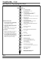
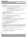
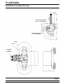
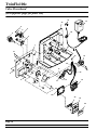
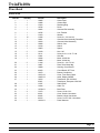
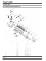
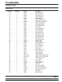
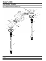
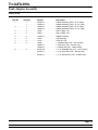
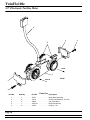
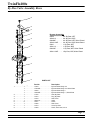
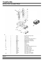
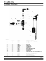
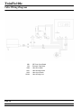
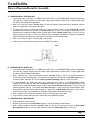
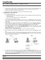
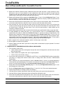
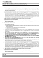
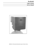
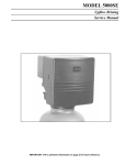
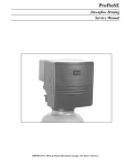
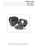
TwinFlo100e Downflow Brining Service Manual Page 2 Printed in U.S.A. TwinFlo100e Table of Contents CONTROL VALVE DATA Specifications . . . . . . . . . . . . . . . . . . . . . . . . . . . . . . . . . . . . . . . . . . . . . . . . . . . . . . . . . . . . . . . . . .4 TIMER PROGRAMMING Calculating Meter Settings. . . . . . . . . . . . . . . . . . . . . . . . . . . . . . . . . . . . . . . . . . . . . . . . . . . . . . . . .5 Quick Reference Programming Flow Chart . . . . . . . . . . . . . . . . . . . . . . . . . . . . . . . . . . . . . . . . . . . .6 Master Programming Reference . . . . . . . . . . . . . . . . . . . . . . . . . . . . . . . . . . . . . . . . . . . . . . . . . . . .7-10 ASSEMBLY Dimensional Drawing. . . . . . . . . . . . . . . . . . . . . . . . . . . . . . . . . . . . . . . . . . . . . . . . . . . . . . . . . . . . .11 INSTALLATION AND START-UP General notes, Tanks, Plumbing and Start Up . . . . . . . . . . . . . . . . . . . . . . . . . . . . . . . . . . . . . . . . .12-13 ASSEMBLIES Valve Power Head . . . . . . . . . . . . . . . . . . . . . . . . . . . . . . . . . . . . . . . . . . . . . . . . . . . . . . . . . . . . . . .14 List of Parts . . . . . . . . . . . . . . . . . . . . . . . . . . . . . . . . . . . . . . . . . . . . . . . . . . . . . . . . . . . . . . . . . .15 Control Valve . . . . . . . . . . . . . . . . . . . . . . . . . . . . . . . . . . . . . . . . . . . . . . . . . . . . . . . . . . . . . . . . . . .16 List of Parts . . . . . . . . . . . . . . . . . . . . . . . . . . . . . . . . . . . . . . . . . . . . . . . . . . . . . . . . . . . . . . . . . .17 Tank Adapters . . . . . . . . . . . . . . . . . . . . . . . . . . . . . . . . . . . . . . . . . . . . . . . . . . . . . . . . . . . . . . . . . .18 List of Parts . . . . . . . . . . . . . . . . . . . . . . . . . . . . . . . . . . . . . . . . . . . . . . . . . . . . . . . . . . . . . . . . . .19 3/4″ Electronic Turbine Meter . . . . . . . . . . . . . . . . . . . . . . . . . . . . . . . . . . . . . . . . . . . . . . . . . . . . . .20 List of Parts . . . . . . . . . . . . . . . . . . . . . . . . . . . . . . . . . . . . . . . . . . . . . . . . . . . . . . . . . . . . . . . . . .20 Brass Bypass Valve and Parts. . . . . . . . . . . . . . . . . . . . . . . . . . . . . . . . . . . . . . . . . . . . . . . . . . . . . .21 Plastic Bypass Valve and Parts . . . . . . . . . . . . . . . . . . . . . . . . . . . . . . . . . . . . . . . . . . . . . . . . . . . . .22 2310 Safety Brine Valve and Parts . . . . . . . . . . . . . . . . . . . . . . . . . . . . . . . . . . . . . . . . . . . . . . . . . .23 Valve Wiring Diagram . . . . . . . . . . . . . . . . . . . . . . . . . . . . . . . . . . . . . . . . . . . . . . . . . . . . . . . . . . . .24 Trouble Shooting . . . . . . . . . . . . . . . . . . . . . . . . . . . . . . . . . . . . . . . . . . . . . . . . . . . . . . . . . . . . . . . .25 Tools for Servicing . . . . . . . . . . . . . . . . . . . . . . . . . . . . . . . . . . . . . . . . . . . . . . . . . . . . . . . . . . . . . . .26 How to Assemble or Disassemble the Valve . . . . . . . . . . . . . . . . . . . . . . . . . . . . . . . . . . . . . . . . . . .27-32 Service Assemblies . . . . . . . . . . . . . . . . . . . . . . . . . . . . . . . . . . . . . . . . . . . . . . . . . . . . . . . . . . . . . .33 Page 3 Printed in U.S.A. TwinFlo100e Valve Specifications ELECTRICAL SPECIFICATIONS 220 or 110 volts, 50/60 Hz, using a plug-in transformer to reduce it to 24 volts ELECTRONIC CONTROLLER Non-Volatile memory. Set program is retained when power fails TEMPERATURE LIMITS 34 - 110° F or 1 - 38° C WATER PRESSURE RANGE 20 - 125 psi or 1.4 - 8.8 Kgf/sq. cm. REGENERATION SETTINGS Gallons/Liters/Cubic meters INLET/OUTLET PIPE SIZE 3/4″ and 1″. See bypass valves for options. VALVE BASE THREAD 2-1/2″, 8 NPSM RISER PIPE 1.05″ Outside Diameter REGENERATION TYPE Upflow or Downflow Valve Body Injector Piston Seals Spacers Rotor Seals Valve O-Rings Timer Available Flows Noryl GTX Noryl Ethylene Propylene Noryl Ethylene Propylene Ethylene Propylene Electronic Meter Service Cv = 3.8 Backwash Cv = 0.8 OPTIONS: INJECTORS DLFC BLFC 0000, 000, 00, 0, 1, 2 0.6 / 0.8 / 1.0 / 1.2 / 1.3 / 1.5 /1.7 / 2.0 / 2.4 .125 / 0.25 / 0.5 BRINING SYSTEM 1610 ACCESSORIES: 2310 Plastic Safety Brine Valve 500 Air Check Upper and Lower Distributors (Fine / Standard / Wide slots) Page 4 Printed in U.S.A. TwinFlo100e Calculating Meter Settings Your TwinFlo100e consists of one valve/controller with a water meter that controls two tanks in an alternating mode. It can be used to remove Hardness, Alkalinity or Nitrates from the water. Consult factory for any other applications. THE TwinFlo100e IS HIGHLY RECOMMENDED FOR (UP - FLOW) COUNTER CURRENT REGENERATION AS IT REGENERATES WITH SOFT WATER. Your TwinFlo100e valve regeneration cycles have been factory preset. YOU MAY NEED TO CHANGE SETTINGS TO REFLECT EQUIPMENT SIZE, SALT DOSAGE AND OTHERS. Salt Dosage: One gallon of water dissolves 3 lbs. of salt One liter of water dissolves 360 grams of salt CALCULATIONS TO SET CONTROLLER Standard Downflow Resin Capacity per unit of resin (Ft^3 or liters) United States of America 30,000 grains 27,000 grains 24,000 grains 20,000 grains 15 lbs. of salt 12 lbs. of salt 9 lbs. of salt 6 lbs. of salt Metric System 68.7 g of CaCO3/l 61.8 g of CaCO3/l 55.0 g of CaCO3/l 45.8 g of CaCO3/l 240 g/l of salt 192 g/l of salt 144 g/l of salt 96 g/l of salt If the selected timer settings are: TIMER SETTINGS: Fast Rinse Backwash Brine & Slow Rinse Time Refill Time = = = = 8 minutes 8 minutes 50 minutes 8 minutes METER SETTINGS: Example: For a 1 cu. ft. softening tank, regenerated with six pounds of salt per cubic foot of resin, installed to soften a water with Total Hardness 342 ppm. Its a good practice to use a 0.9 factor to calculate the equipments capacity. It will give you a 10% safety margin. Tank Total Capacity = (20,000 gr/cu.ft.)x(1 cu.ft./Regeneration)x(0.9) Tank Total Capacity = 18,000 gr/Regeneration Total Hardness(TH) = (342 ppm)/17.1 = 20 grains/gallon Equipment Capacity= (18,000 gr/Regeneration)/(20 gr/gallon) = 900 gallons/Regeneration Since the TwinFlo100e regenerates with soft water, subtract the regeneration water from the Equipment capacity to get the meter settings. REGENERATION WATER: For a unit with a DLFC = 2, BLFC - 0.25 and #0 Injector. Fast Rinse = (8 minutes) x (DLFC) = (8) x (2) = Backwash = (8 minutes) x (DLFC) = (8) x (2) = Brine & Slow R. = (50 minutes) x (Slow R.) = (50)x(0.3) = Brine Tank Refill = (8 minutes) x (BLFC) = (8)x(0.25) = Total Regeneration Water = 16.0 gallons 16.0 gallons 15.0 gallons 2.0 gallons 49.0 gallons Set water meter at = (Equipment Capacity) - (Regeneration water) Set water meter at = 900 gallons - 49.0 gallons = 851.0 gallons Page 5 Printed in U.S.A. TwinFlo100e - V2.0 Quick Reference Programming Flow Chart Units U-1 = Gallons and US time U-2 = Liters & 24 Hr. time U-4 = Cubic meters & 24 Hr. time Regeneration Type 7-1 = Timeclock delayed, 7-3 = Meter delayed, 7-2 = Meter immediate (TwinFlo100e) Treated Water Capacity XXXX water meter setting in gallons, liters or cubic meters Regeneration Time This display will not be shown when regeneration type is meter immediate. Regeneration Day Override A-x, x = Sets maximum amount of days between regenerations. Water meter override A-OFF = No override GENERAL INSTRUCTIONS 1. Push extra cycle button once per display until all displays are programmed and normal operation is resumed. Fast Rinse Of Standby Unit Before Going On Line 1-x, x = minutes 2. Option setting displays may be changed as required by pushing either the UP or DOWN arrows Backwash Exhausted Unit 2-x, x = minutes 3. Certain displays will not be viewed depending on current valve program. Brine Draw And Slow Rinse Of Exhausted Unit 3-x, x = minutes TO PROGRAM: 1. Set time of day display to 12:01 P.M. for the US or 12:01 in the metric system. Brine Refill 4-x, x = minutes 2. To start programming, push and hold the UP and DOWN arrows simultaneously until the program light indicator comes on (approximately five seconds). Make sure that the time of day does not change: Regeneration Cycle Step #5 5-Off, Off = Cancelled Water Meter Pulse Rate Set at 132 for (TwinFlo100e) US format Set at 34.9 for (TwinFlo100e) metric formats Control Valve Type Set at o-2 (TwinFlo100e) Unit In Service (On Line) Indicator -U1- or -U2- Set to match number on gear below motor Electrical Line Frequency LF60 = 60 Hertz (cycles) LF50 = 50 Hertz Master Programming Mode is Exited Normal Operation is Resumed Page 6 Printed in U.S.A. TwinFlo100e Master Programming Reference Service Flow Program P.M. Set Up Button Set Down Button Extra Cycle Button Regeneration Display Step 1 - Rinse Step 3 - Brine/Rinse Step 2 - Backwash Step 4 - Brine Refill NOTE #1: The time of day can be changed at any time during the service mode by depressing the UP or DOWN arrows. NOTE #2: Manual regeneration can be initiated at any time during the service mode by depressing the Extra Cycle Button (ECB). TwinFlo100e is to be programmed for immediate regeneration (7-2) and the manual regeneration starts immediately. NOTE #3: Always change the timer factory settings to the ones for your specific application. NOTE #4: When left inactive for five (5) minutes, in the programming mode, the control will exit this mode, without storing any new settings, and it will resume normal operation. Enter the Master Programming Mode to view the current program or to re-program the unit. Depending on current option settings, some displays will not be shown. Entering Master Programming Mode Set time of day at 12:01 p.m. in the US System (U-1) or at 12:01 in the metric system (U-2, or U-4 for the 24 hours military time). Push and hold the UP and DOWN arrows simultaneously, making sure that the time of day does not change, until the program light indicator comes on (approximately five seconds) and the first display is viewed. 1. US/Metric Display Format (U) This display is used to set the desired display format. This option setting is identified by the letter (U) in the first digit. There are three possible settings: Example: [ U - - 1 ] for US gallons Metric format uses liters or cubic meters with a 24-hour timekeeping format. Regeneration timing in tenths of minutes. Example: [ U - - 2 ] for liters [ U - - 4 ] for cubic meters The set UP or DOWN buttons will adjust this value. Depress the Extra Cycle Button to proceed to the next step. Page 7 Printed in U.S.A. TwinFlo100e Master Programming Reference (Cont’d.) 2. Regeneration Type (7) This display is used to set the regeneration type. This option setting is identified by the number (7) in the first digit. There are three possible settings with [7-2] being the desired option for TwinFlo100e: Example: [ 7 - - 1 ] Timeclock delayed, not typically used with the TwinFlo100e [ 7 - - 2 ] Meter immediate, the regeneration is started immediately after the meter zeroes down Setting used with the TwinFlo100e. [ 7 - - 3 ] Meter delayed, after the meter zeroes, the unit will regenerate at a pre-selected regeneration time. Setting not typically used with the TwinFlo100e. The set UP or DOWN buttons will adjust this value. Depress the Extra Cycle Button to proceed to the next step. 3. Treated Water Capacity (No display code) This display is used to set the equipment capacity in volume of treated water (gallons/liters/cubic meters) between regenerations. Example: Using UP and Down buttons to set the calculated volume figure [ It will be gallons, liters or cubic meters if it is [ 851] U - 1 ], [ U - 2 ] or [ U - 4 ] Depress the Extra Cycle Button to proceed to the next step. 4. Regeneration Time (No Display Code) It should not be viewed if the existent program is set for the TwinFlo100e, immediate regeneration. This model will regenerate immediately after the water meter setting comes down to zero regardless of the time of day. Example: 2:00 am regeneration time [ 2:00 pm regeneration time 2:00 ] with P.M. indicator dot off. [ 2:00 ] with P.M. indicator dot on. The set UP or DOWN buttons will adjust this value. Depress the Extra Cycle Button to proceed to the next step. 5. Regeneration Day Override (A) This display is used to set the maximum amount of days the unit can be in service without regenerating. This option setting is identified by the letter (A) in the first digit. When a Day Override has been selected, the unit will regenerate at the same point in time it regenerated the previous time if the unit has been programmed for immediate regeneration. With a timeclock or a meter delayed program, the unit will regenerate at the set Regeneration Time. An [AOFF] setting will cancel this feature with all regeneration types except timeclock regeneration. Example: Override every 7 days [A--7] Cancel setting [ A OFF ] for meter immediate or delayed regeneration only. The set UP and Down buttons will adjust this value. Depress the Extra Cycle Button to proceed to the next step. Page 8 Printed in U.S.A. TwinFlo100e Master Programming Reference (Cont’d.) 6. Regeneration Cycle Step Programming (1) (2) (3) (4) (5) (6) The next 1-4 displays viewed are part of a series of option settings used to program the Regeneration Cycle. Up to 4 steps can be programmed. Each display is used to set the duration time in minutes (or tenths of minutes - Metric) of that specific step in a regeneration cycle. A step # will turn on for the regeneration cycle step being programmed. Regeneration steps are skipped by setting the display to 0 and regeneration ended by setting the step # after the last active step to OFF, as shown below and on the next page: Setting the display to 0 skips regeneration steps and the regeneration is ended by setting the last step to OFF. Example: [1--8] Backwash Cycle step #2 - 8 minutes [ 2 - - 8 ] Brine/Rinse Cycle step #3 - 50 minutes [ 3 - 50 ] Brine Refill Cycle step #4 - 8 minutes [ 4 - - 8 ] Rinse Cycle step #1 - 8 minutes US Format US Format US Format US Format Other examples: Metric cycle step #4 [ 2 - - 0 ] US Format [ 4 - 8.5 ] Metric Format Regeneration is ended [ 5 OFF ] Both Formats. Not used on the TwinFlo100e. Skipped cycle step #2 Depress the Extra Cycle Button once per display to advance through Regeneration Cycle Step Programming. The set UP or DOWN buttons will adjust this value. Calculate your Brine Refill time based on your desired salt dosage and your refill rate controlled by the selected Brine Line Flow Control (BLFC). See page 5. Example: Refill Time= (Lbs. of salt) /(3)/(Selected BLFC) = (12/(3)/(0.25) = 16 minutes Depress the Extra Cycle Button to proceed to the next step. 7. Flow Meter Size (F) This display is used to set the meter pulse for the control valve used. This option setting is identified by the letter F in the first digit. In this display, set the proper amount of pulses generated by the flow meter for each US gallon or liter of water flow. The same metric setting is used for liters or cubic meters. Example: [ F 1 3 2 ] 3/4″ Turbine Flow Meter (US Format) [ F 3 4.9 ] 3/4″ Turbine Flow Meter (Metric Formats) The set UP or DOWN buttons will adjust this value. Depress the Extra Cycle Button to proceed to the next step. 8. Valve Type (o) This display is used to set the type of valve used with the control. This option setting is identified by the letter [o] in the first digit. There are two possible selections with #2 being the required setting. Examples: [ o - - 1 ] Setting not used for the TwinFlo100e [ o - - 2 ] Used on the TwinFlo100e The set UP or DOWN buttons will adjust this value. Depress the Extra Cycle Button to proceed to the next step. Page 9 Printed in U.S.A. TwinFlo100e Master Programming Reference (Cont’d.) 9. Tank In Service This display is used to identify which tank is in service. Look for the number indicated on gear below motor. Tank #1 is on the right when you are facing the TwinFlo100e. Tank #2 is on the left. Example: [ o - U1 ] Tank #1 in service [ o - U2 ] Tank #2 in service 10. Line Frequency (LF) This display is used to set the frequency of the power applied to the control. When properly set, all timekeeping functions will remain accurate. This option setting is identified by the letters LF in the first two digits. There are two possible selections. Example: [ L F 5 0 ] 50Hz Line frequency Operation. [ L F 6 0 ] 60Hz Line frequency Operation. Exiting This Option Setting Level Push the Extra Cycle Button once per display until all have been viewed. The Program Mode will be exited and normal operation resumed. Resetting Permanent Programming Memory Push and hold the Set Up and Down Buttons for 25 seconds or until the Time Of Day Display resets to 12:00 P.M. All option settings will then reset to default values. Control programming will then have to be reset as necessary. Page 10 Printed in U.S.A. TwinFlo100e Installation/Assembly Drawing 10.83 2.45 DRAIN, QUICK CONNECT WITH 1/2″ NPT FEMALE THD. 3.60 .75 1.16 5.30 8.36 BRINE TANK CONNECTION 3/8″ TUBE FITTING 10″ TANK 7″ TANK 2.00 1″ NPT MALE OR 3/4″ NPT MALE 7.96 Page 11 Printed in U.S.A. TwinFlo100e Installation & Start-Up GENERAL NOTES: 1. Locate the two treatment tanks and the brine tank as close as possible to a floor drain and to each other on a smooth, clean, level and firm surface. 2. Water pressure must be between: 20 - 125 psi (1.4 - 8.8 Kgf/sq.cm.). Install pressure reducer if necessary. 3. All electrical connections should be done according to local codes. A 120V, 50/60 Hz or 220V, 50/60 Hz electric supply is needed. Be sure that a remote switch can not turn off the receptacle. A power cord with a transformer is supplied to bring the power down to 24V to operate the valve. 4. Replace any existing plumbing, which is heavily scaled with hardness or fouled with corrosion products. 5. Allow 6″ - 12″ (150 - 300 mm) behind the TwinFlo100e and four feet (1.22 m) above it for ease of installation and service. 6. The existing drain must be able to handle the TwinFlo100e backwash flow rate. TANKS: 1. Both treatment tanks must be the same height and diameter, and must be filled with equal amounts of media. 2. Place a 1.05″ OD distributor tube with an installed collector on the bottom of each tank. Make sure the distributors are centered and rest at the lowest point in the bottom of each tank. Mark distributors flush with the top of each tank, remove and cut each tube evenly at the mark. File, cut, or sand an outside bevel on the tube assuring that there will be no o-ring damage when installing tank adapters. 3. After locating the tanks, install the distributor tubes with their openings temporarily covered to prevent resin from entering. Manually place enough water into each tank to be 2″ over the lower distributors for cushioning purposes. If used, install and level under-bed material. Using a large funnel, and while keeping the tube centered, pour the proper volume of resin into each tank. 4. Using only silicone lubricant, lubricate both distributors o-rings (inside tank adapters) and tank o-rings (near tank thread on adapters). Uncover distributor tubes top openings and assemble the tanks, tank adapters, and distributor tubes, making sure that the distributor tubes properly engage into the tank adapters. 5. Align and install the tanks with tank adapters to the TwinFlo100e. Be sure to match the numbers on the tank adapters to the corresponding numbers on the TwinFlo100e. Number one is on the right of the valve as you face it. PLUMBING: 1. All plumbing should be done according to local codes. 2. Proper pipe alignment and support is required to prevent locking the turbine meter. 3. Install bypass valve or plumbing adapter being sure that the connecting clips are firmly seated and tightened. Failure to do so may cause meter malfunction. Inlet and outlet valve ports are identified with white arrows. Meter cable socket must be on top. Use only Teflon tape on pipe threads. All necessary adjacent soldering must be done before connections to TwinFlo100e are made. Failure to do this may damage plastic parts. Installation of a bypass valve is recommended. 4. Install a 1/2″ I.D. drain line making sure to keep its maximum height no more than 4′ above the TwinFlo100e. Many plumbing code restrictions apply to drains (Air gaps, anti-siphon devices, others). Be sure these are understood and followed. 5. Connect a 3/8″ O.D. x 1/4″ I.D. polyethylene brine line between the TwinFlo100e and the 2310 safety brine valve in the brine tank. Add water to brine tank up to the top of the air check. Page 12 Printed in U.S.A. TwinFlo100e Installation and Start-Up START-UP: 1. Open bypass valve and turn on the nearest treated cold water faucet. Allow water to run 2 - 3 minutes to clear pipes of solder or other material loosened during installation. 2. Plug TwinFlo100e to electrical outlet. Press up or down arrows to set the correct time of day. REVIEW QUICK REFERENCE PROGRAMMING FLOW CHART ON PAGE 6. 3. Position the bypass valve to service (close bypass). Allow water to enter slowly into the media tank. Run water for five minutes through the open faucet to rid tank of entrapped air. One tank is now full of water but still contains some air. 4. Push the “extra cycle button” to manually regenerate the tank just filled. The first cycle is to PRE RINSE the unit on standby before it goes to service. Allow water to enter slowly into the standby media tank. Run water for five minutes through the open faucet to rid tank of entrapped air. The standby media tank is now full of water but still contains some air. 5. Push the “extra cycle button” to manually advance valve to BACKWASH. Air is rapidly expelled in this cycle and media may be lost if flow is not restricted. . Be sure that the inlet shut off valve is only slightly open during this step. 6. Push the “extra cycle button” to manually advance the valve to the BRINE/RINSE position to draw the excess water in the brine tank down to the air check level. 7. Push the “extra cycle button” to manually advance the valve to the BRINE REFILL position. Allow the timer to run its predetermined time to ensure the proper refill volume for the desired salt dosage. Review that the water level in the brine tank is above the salt grid. Allow valve to automatically return to SERVICE. 8. Start another regeneration to remove the air from the first tank. Repeat all cycle steps, including the slightly open inlet valve but do not include neither drawing or refill time. 9. Fill brine tank with salt. Page 13 Printed in U.S.A. TwinFlo100e Valve Powerhead (See opposite page for parts list) 18 27 30 8 7 6 5 28 9 2 4 3 1 31 16 8 31 18 19 31 15 8 31 29 10 13 20 35 21 8 8 8 8 14 23 15 12 8 8 22 24 25 26 Page 14 Printed in U.S.A. TwinFlo100e Powerhead Parts List Item No. Quantity 1. . . . . . . . . . . 1 . . . . . . . . . . . 2. . . . . . . . . . . 1 . . . . . . . . . . . 3. . . . . . . . . . . 2 . . . . . . . . . . . 4. . . . . . . . . . . 1 . . . . . . . . . . . 5. . . . . . . . . . . 1 . . . . . . . . . . . 6. . . . . . . . . . . 1 . . . . . . . . . . . 7. . . . . . . . . . . 1 . . . . . . . . . . . 8 . . . . . . . . . . . 14 . . . . . . . . . . 9. . . . . . . . . . . 1 . . . . . . . . . . . 10 . . . . . . . . . . 1 . . . . . . . . . . . 12 . . . . . . . . . . 1 . . . . . . . . . . . 13 . . . . . . . . . . 2 . . . . . . . . . . . 14 . . . . . . . . . . 1 . . . . . . . . . . . 15 . . . . . . . . . . 2 . . . . . . . . . . . 16 . . . . . . . . . . 2 . . . . . . . . . . . 18 . . . . . . . . . . 4 . . . . . . . . . . . 19 . . . . . . . . . . 1 . . . . . . . . . . . 20 21 22 23 24 25 26 27 .......... .......... .......... .......... .......... .......... .......... .......... 2 1 1 1 1 1 1 1 ........... ........... ........... ........... ........... ........... ........... ........... 28 29 30 31 32 33 34 35 .......... .......... .......... .......... .......... .......... .......... .......... 1 1 1 4 1 2 2 1 ........... ........... ........... ........... ........... ........... ........... ........... Part No. 19890 . . . . . . . . . . . . . . . 14896 . . . . . . . . . . . . . . . 15810 . . . . . . . . . . . . . . . 18796 . . . . . . . . . . . . . . . 19062 . . . . . . . . . . . . . . . 18785 . . . . . . . . . . . . . . . 13363 . . . . . . . . . . . . . . . 13296 . . . . . . . . . . . . . . . 19061 . . . . . . . . . . . . . . . 19354 . . . . . . . . . . . . . . . 19940 . . . . . . . . . . . . . . . 10218 . . . . . . . . . . . . . . . 18803 . . . . . . . . . . . . . . . 10339 . . . . . . . . . . . . . . . 19111 . . . . . . . . . . . . . . . 12681 . . . . . . . . . . . . . . . 19046 . . . . . . . . . . . . . . . 18898 . . . . . . . . . . . . . . . 11384 . . . . . . . . . . . . . . . 18807 . . . . . . . . . . . . . . . 19889 . . . . . . . . . . . . . . . 40283 . . . . . . . . . . . . . . . 19473 . . . . . . . . . . . . . . . 19471-02 . . . . . . . . . . . . . 19697-03 . . . . . . . . . . . . . 19674 . . . . . . . . . . . . . . . 25651 . . . . . . . . . . . . . . . 13547 . . . . . . . . . . . . . . . 14044 . . . . . . . . . . . . . . . 18798-01 . . . . . . . . . . . . . 12473 . . . . . . . . . . . . . . . 40231 . . . . . . . . . . . . . . . 40232 . . . . . . . . . . . . . . . 40274 . . . . . . . . . . . . . . . 19474-01 . . . . . . . . . . . . . Description Center Plate Geneva Disk Retaining Ring Pinion Gear and Pin Assembly Link, Transfer Washer Screw, 6 x 1/2″ Hex Hd. Gear and Cam Assembly Downflow Gear and Label Assembly Switch, Cam Switch Spacer Nut, 4-40 Screw, 4-40 x 1-1/2″ Fl. Hd. Wire Nut Motor, 24V/50 Hz Motor, 24V/60 Hz Screw, 6 x 1/4″ Fill. Hd. Plate, Drive Motor Mtg. Housing, Circuit Board Circuit Board, SE Timer Buttons, Conductive Cover, Front Panel, Black Label, Display 5600SE Transformer, US 120V/24V Transformer, European 230V/24V Strain Relief Cable Tie Back Plate Screw, 10-20 x 5/8″ Cover, Smoke, Not shown Bracket, Hinge, Not shown Screw, 1/4-20 x 3/8″, Not shown Power Harness Page 15 Printed in U.S.A. TwinFlo100e Control Valve (See opposite page for parts list) 20 19 18 Item No. Quantity Part No. 1. . . . . . . . . . . 1 . . . . . . . . . . . .18770-01 . . . . . . . . . . . . . 2. . . . . . . . . . . 1 . . . . . . . . . . . .18783 . . . . . . . . . . . . . . . . 3. . . . . . . . . . . 1 . . . . . . . . . . . .19004 . . . . . . . . . . . . . . . . 4. . . . . . . . . . . 1 . . . . . . . . . . . .19005 . . . . . . . . . . . . . . . . 5. . . . . . . . . . . 1 . . . . . . . . . . . .19054 . . . . . . . . . . . . . . . . 6. . . . . . . . . . . 1 . . . . . . . . . . . .19055 . . . . . . . . . . . . . . . . 7. . . . . . . . . . . 1 . . . . . . . . . . . .19056 . . . . . . . . . . . . . . . . 8. . . . . . . . . . . 1 . . . . . . . . . . . .19057 . . . . . . . . . . . . . . . . 9. . . . . . . . . . . 1 . . . . . . . . . . . .18782 . . . . . . . . . . . . . . . . 10 . . . . . . . . . . 1 . . . . . . . . . . . .18874 . . . . . . . . . . . . . . . . 11 . . . . . . . . . . 1 . . . . . . . . . . . .18875 . . . . . . . . . . . . . . . . 12 . . . . . . . . . . 1 . . . . . . . . . . . .18876 . . . . . . . . . . . . . . . . Page 16 Printed in U.S.A. Description Valve Body, Machined Cage Seal, Molded Inlet Seal, Molded Outlet Seal, O-Ring, -124 Seal, O-Ring, -128 Seal, O-Ring, -129 Seal, O-Ring, -133 Rotor Seal, Q-Ring, -118 Seal, Q-Ring, -121 Seal, Q-Ring, -123 TwinFlo100e Control Valve Parts List Item No. Quantity Part No. 13 . . . . . . . . . . . 1 . . . . . . . . . . . . 18877. . . . . . . . . . . . . . . . 14 . . . . . . . . . . . 1 . . . . . . . . . . . . 18781. . . . . . . . . . . . . . . . 15 . . . . . . . . . . . 1 . . . . . . . . . . . . 14926. . . . . . . . . . . . . . . . 16 . . . . . . . . . . . 1 . . . . . . . . . . . . 18776. . . . . . . . . . . . . . . . 17 . . . . . . . . . . . 1 . . . . . . . . . . . . 18784. . . . . . . . . . . . . . . . 18 . . . . . . . . . . . 1 . . . . . . . . . . . . 15820. . . . . . . . . . . . . . . . 19 . . . . . . . . . . . 1 . . . . . . . . . . . . 13245. . . . . . . . . . . . . . . . 20 . . . . . . . . . . . 1 . . . . . . . . . . . . 60022-xx . . . . . . . . . . . . . 21 . . . . . . . . . . . 4 . . . . . . . . . . . . 18871. . . . . . . . . . . . . . . . 22 . . . . . . . . . . . 4 . . . . . . . . . . . . 18870. . . . . . . . . . . . . . . . 23 . . . . . . . . . . . 1 . . . . . . . . . . . . 19667. . . . . . . . . . . . . . . . 24 . . . . . . . . . . . 1 . . . . . . . . . . . . 18779. . . . . . . . . . . . . . . . 25 . . . . . . . . . . . 1 . . . . . . . . . . . . 19237. . . . . . . . . . . . . . . . 26 . . . . . . . . . . . 1 . . . . . . . . . . . . 18808. . . . . . . . . . . . . . . . 27 . . . . . . . . . . . 1 . . . . . . . . . . . . 14925. . . . . . . . . . . . . . . . 28 . . . . . . . . . . . 1 . . . . . . . . . . . . 12626. . . . . . . . . . . . . . . . 29 . . . . . . . . . . . 2 . . . . . . . . . . . . 13302. . . . . . . . . . . . . . . . 30 . . . . . . . . . . . 1 . . . . . . . . . . . . 12550. . . . . . . . . . . . . . . . 31 . . . . . . . . . . . 1 . . . . . . . . . . . . 13167. . . . . . . . . . . . . . . . 32 . . . . . . . . . . . 1 . . . . . . . . . . . . 13165. . . . . . . . . . . . . . . . 33 . . . . . . . . . . . 1 . . . . . . . . . . . . 11973. . . . . . . . . . . . . . . . 34 . . . . . . . . . . . 1 . . . . . . . . . . . . 16098. . . . . . . . . . . . . . . . 35 . . . . . . . . . . . 1 . . . . . . . . . . . . 11981-01 . . . . . . . . . . . . . 36 . . . . . . . . . . . 1 . . . . . . . . . . . . 18786. . . . . . . . . . . . . . . . 37 . . . . . . . . . . . 1 . . . . . . . . . . . . 18777. . . . . . . . . . . . . . . . 38 . . . . . . . . . . . 1 . . . . . . . . . . . . 18809. . . . . . . . . . . . . . . . 39 . . . . . . . . . . . 4 . . . . . . . . . . . . 12112. . . . . . . . . . . . . . . . 40 . . . . . . . . . . . 1 . . . . . . . . . . . . 18276. . . . . . . . . . . . . . . . 41 . . . . . . . . . . . 2 . . . . . . . . . . . . 10141. . . . . . . . . . . . . . . . 42 . . . . . . . . . . . 2 . . . . . . . . . . . . 13771. . . . . . . . . . . . . . . . 43 . . . . . . . . . . . 1 . . . . . . . . . . . . 18810. . . . . . . . . . . . . . . . 44 . . . . . . . . . . . 1 . . . . . . . . . . . . 18273. . . . . . . . . . . . . . . . 45 . . . . . . . . . . . 1 . . . . . . . . . . . . 18274-XXX . . . . . . . . . . . 46 . . . . . . . . . . . 1 . . . . . . . . . . . . 18275-XXX . . . . . . . . . . . 47 . . . . . . . . . . . 1 . . . . . . . . . . . . 15243. . . . . . . . . . . . . . . . 48 . . . . . . . . . . . 1 . . . . . . . . . . . . 18774. . . . . . . . . . . . . . . . 49 . . . . . . . . . . . 2 . . . . . . . . . . . . 17063. . . . . . . . . . . . . . . . 50 . . . . . . . . . . . 1 . . . . . . . . . . . . 12977. . . . . . . . . . . . . . . . 51 . . . . . . . . . . . 1 . . . . . . . . . . . . 13244-01 . . . . . . . . . . . . . 52 . . . . . . . . . . . 1 . . . . . . . . . . . . 10332. . . . . . . . . . . . . . . . 53 . . . . . . . . . . . 1 . . . . . . . . . . . . 10330. . . . . . . . . . . . . . . . 54 . . . . . . . . . . . 1 . . . . . . . . . . . . 10329. . . . . . . . . . . . . . . . 55 . . . . . . . . . . . 1 . . . . . . . . . . . . 11385-01 . . . . . . . . . . . . . 56 . . . . . . . . . . . 1 . . . . . . . . . . . . 11183. . . . . . . . . . . . . . . . 57 . . . . . . . . . . . 1 . . . . . . . . . . . . 12338. . . . . . . . . . . . . . . . 58 . . . . . . . . . . . 1 . . . . . . . . . . . . 18312. . . . . . . . . . . . . . . . Description Seal, Q-Ring, -126 End Plug, Rotor Seal, Q-Ring, -012 Shaft, Rotor Drive Crank, Transfer Seal, O-Ring, -134 Retainer, BLFC Button BLFC Button, Specify Size Spacer, Regeneration Seal, Regeneration Piston, Regeneration Piston Rod End Plug Assembly Pin, Drive Roller Brine, Valve Stem Seat, Brine Valve Seal, O-Ring, -014 Seal, Q-Ring, -009 Spacer, Brine Valve Cap, Brine Valve Spring, Brine Valve Washer, Nylon Retaining Ring Spacer, Brine Valve Plate, Retainer Pin, Cam Bearing Screw, 10 x 1/2″ Plug, Injector Seal, O-Ring, -010 Seal, O-Ring, -012 Screen, Injector Vortex Generator Injector Nozzle - Specify Size Injector Throat - Specify Size Seal, O-Ring, -028 Cover, Injector Screw, 10 x 1″ Seal, O-Ring, -015 Adapter, BLFC Insert, 3/8″ Sleeve, 3/8″, Delrin Nut, 3/8″ Tube Fitting Flow Control Hsg., Plastic Seal, O-Ring, -017 Hose Barb Retainer, DLFC Page 17 Printed in U.S.A. TwinFlo100e Tank Adapter Assembly (See opposite page for parts list) 8 9 8 9 Page 18 Printed in U.S.A. TwinFlo100e Tank Adapter Assembly Parts List Item No. Quantity 1. . . . . . . . . . . 1 . . . . . . . . . . . 1 ........... 2. . . . . . . . . . . 1 . . . . . . . . . . . 1 ........... 3. . . . . . . . . . . 2 . . . . . . . . . . . 4. . . . . . . . . . . 2 . . . . . . . . . . . 5. . . . . . . . . . . 4 . . . . . . . . . . . 6. . . . . . . . . . . 4 . . . . . . . . . . . 7. . . . . . . . . . . 4 . . . . . . . . . . . 8. . . . . . . . . . . 2 . . . . . . . . . . . Part No. 19242-01 . . . . . . . . . . . . . 19242-03 . . . . . . . . . . . . . 19242-02 . . . . . . . . . . . . . 19242-04 . . . . . . . . . . . . . 13304 . . . . . . . . . . . . . . . 18303 . . . . . . . . . . . . . . . 15078-01 . . . . . . . . . . . . . 13255 . . . . . . . . . . . . . . . 13314 . . . . . . . . . . . . . . . 18280 . . . . . . . . . . . . . . . 18280-01 . . . . . . . . . . . . . 18280-02 . . . . . . . . . . . . . 9 . . . . . . . . . . . 2 . . . . . . . . . . . 60795 -00 . . . . . . . . . . . . 60795-01 . . . . . . . . . . . . . 60795-01 . . . . . . . . . . . . . Description Adapter Assembly, Tank 1, 6″-8″ Tanks Adapter Assembly, Tank 1, 9″-10″ Tanks Adapter Assembly, Tank 2, 6″-8″ Tanks Adapter Assembly, Tank 2, 9″-10″ Tanks Seal, O-Ring, -121 Seal, O-Ring, -336 Adapter Coupling Clip, Mounting Screw, 8 x 5/8″ 1″ Standard Slot (.010 - .012 slot size) 1″ Wide Slot (.019 - .022 slot size) 1″ Narrow Slot (.007 - .009 slot size) 1″ x 72″ Standard Slot (.010 - .012 slot size) 1″ x 72″ Wide Slot (.019 - .022 slot size) 1″ x 72″ Narrow Slot (.007 - .009 slot size) Page 19 Printed in U.S.A. TwinFlo100e 3/4″ Electronic Turbine Meter 4 3 5 INLET 1 OUTLET 3 VALVE 2 Parts List Item No. Quantity Part No. Description 1 . . . . . . . . . . . 1. . . . . . . . . . . . 19797. . . . . . . . . . . . . . . . Meter Body Assembly 2 . . . . . . . . . . . 2. . . . . . . . . . . . 13314. . . . . . . . . . . . . . . . Screw, Hex Washer, 8-18 x 5/8″ 3 . . . . . . . . . . . 2. . . . . . . . . . . . 19569. . . . . . . . . . . . . . . . Clip, Flow Meter 4 . . . . . . . . . . . 1. . . . . . . . . . . . 19791-01 . . . . . . . . . . . . . Electrical Harness 5 . . . . . . . . . . . 4. . . . . . . . . . . . 13305. . . . . . . . . . . . . . . . O-Ring, -119 Page 20 Printed in U.S.A. 2 TwinFlo100e By-Pass Valve Assembly, Brass 9 8 6 5 By-pass Assemblies 60040 . . . . . . . . . . 3/4″ By-Pass, NPT 60040-10 . . . . . . . . 3/4″ By-Pass, BSP 60040NP . . . . . . . . 3/4″ By-Pass, NPT, Nickel Plated 60040-10NP . . . . . 3/4″ By-Pass, BSP, Nickel Plated 60041 . . . . . . . . . . 1″ By-Pass, NPT 60041-10 . . . . . . . . 1″ By-Pass, BSP 60041NP . . . . . . . . 1″ By-Pass, NPT, Nickel Plated 60041-10NP . . . . . 1″By-Pass, BSP, Nickel Plated 4 3 1 2 7 6 PARTS LIST Item No. Quantity 1 . . . . . . . . . . . .1 . . . . . . . . . . . . 1. . . . . . . . . . . . 1. . . . . . . . . . . . 1. . . . . . . . . . . . 2 . . . . . . . . . . . .1 . . . . . . . . . . . . 3 . . . . . . . . . . . .1 . . . . . . . . . . . . 4 . . . . . . . . . . . .1 . . . . . . . . . . . . 5 . . . . . . . . . . . .1 . . . . . . . . . . . . 6 . . . . . . . . . . . .8 . . . . . . . . . . . . 7 . . . . . . . . . . . .1 . . . . . . . . . . . . 8 . . . . . . . . . . . .1 . . . . . . . . . . . . 9 . . . . . . . . . . . .1 . . . . . . . . . . . . Part No. Description 17290 . . . . . . . . . . . . . . . . 17290NP . . . . . . . . . . . . . . 13399 . . . . . . . . . . . . . . . . 13399NP . . . . . . . . . . . . . . 11726 . . . . . . . . . . . . . . . . 11972 . . . . . . . . . . . . . . . . 11978 . . . . . . . . . . . . . . . . 13604-01. . . . . . . . . . . . . . 15727 . . . . . . . . . . . . . . . . 11986 . . . . . . . . . . . . . . . . 11979 . . . . . . . . . . . . . . . . 11989 . . . . . . . . . . . . . . . . By-Pass Valve Body, 3/4″ By-Pass Valve Body, 3/4″ Nickel Plate By-Pass Valve Body, 1″ By-Pass Valve Body, 1″, Nickel Plate Seal, By-Pass Plug, By-Pass Side Cover Label Screw Side Cover Lever, By-Pass Screw, Hex Head, 1/4-14 Page 21 Printed in U.S.A. TwinFlo100e By-Pass Valve Assembly, Plastic 8 5B 5A 6 7 1 2 3 4 12C 11 10 9 12A 12B Item No. Quantity 1. . . . . . . . . . . 1 . . . . . . . . . . . 2. . . . . . . . . . . 1 . . . . . . . . . . . 3. . . . . . . . . . . 1 . . . . . . . . . . . 4. . . . . . . . . . . 2 . . . . . . . . . . . 5A . . . . . . . . . . 1 . . . . . . . . . . . 5B . . . . . . . . . . 1 . . . . . . . . . . . 6. . . . . . . . . . . 4 . . . . . . . . . . . 7. . . . . . . . . . . 2 . . . . . . . . . . . 8. . . . . . . . . . . 2 . . . . . . . . . . . 9. . . . . . . . . . . 2 . . . . . . . . . . . 10 . . . . . . . . . . 2 . . . . . . . . . . . 11 . . . . . . . . . . 2 . . . . . . . . . . . 12A . . . . . . . . . 1 . . . . . . . . . . . 1 ........... 12B . . . . . . . . . 1 . . . . . . . . . . . 1 ........... 1 ........... 1 ........... 12C . . . . . . . . . 1 . . . . . . . . . . . Part No. 19723 . . . . . . . . . . . . . . . 11183 . . . . . . . . . . . . . . . 19724 . . . . . . . . . . . . . . . 17512 . . . . . . . . . . . . . . . 17820 . . . . . . . . . . . . . . . 17820-01. . . . . . . . . . . . . 18661 . . . . . . . . . . . . . . . 18662 . . . . . . . . . . . . . . . 18660 . . . . . . . . . . . . . . . 13305 . . . . . . . . . . . . . . . 13255 . . . . . . . . . . . . . . . 13314 . . . . . . . . . . . . . . . 18706 . . . . . . . . . . . . . . . 18706-02. . . . . . . . . . . . . 13708 . . . . . . . . . . . . . . . 13708NP . . . . . . . . . . . . . 13398 . . . . . . . . . . . . . . . 13398NP . . . . . . . . . . . . . 19620 . . . . . . . . . . . . . . . Page 22 Printed in U.S.A. Description By-Pass Valve Body, Plastic O-Ring, -015 Cap, By-Pass Screw, Hex Washer Head, #6-24 x 3 Plug, By-Pass, Inlet (White) Plug, By-Pass, Outlet (White) O-Ring, -218 Retaining Ring O-Ring O-Ring, -119 Clip, Mounting Screw, Hex Washer Head, 8-18 x 5/8 Yoke, Plastic, 1″ NPT Yoke, Plastic, 3/4″ NPT Yoke, Brass, 3/4″ NPT Yoke, 3/4″ NPT Nickel Plated Yoke, Brass, 1″ NPT Yoke, 1″ NPT Nickel Plated Yoke, Plastic, 3/4″, 90 °NPT TwinFlo100e 2310 Safety Brine Valve Item No. Quantity 1. . . . . . . . . . . 1 . . . . . . . . . . . 2. . . . . . . . . . . 1 . . . . . . . . . . . 3. . . . . . . . . . . 1 . . . . . . . . . . . 4. . . . . . . . . . . 1 . . . . . . . . . . . 5. . . . . . . . . . . 1 . . . . . . . . . . . 6. . . . . . . . . . . 1 . . . . . . . . . . . 7. . . . . . . . . . . 1 . . . . . . . . . . . 8. . . . . . . . . . . 1 . . . . . . . . . . . 9. . . . . . . . . . . 2 . . . . . . . . . . . 10 . . . . . . . . . . 1 . . . . . . . . . . . 11 . . . . . . . . . . 1 . . . . . . . . . . . 12 . . . . . . . . . . 2 . . . . . . . . . . . 13 . . . . . . . . . . 1 . . . . . . . . . . . 14 . . . . . . . . . . 1 . . . . . . . . . . . Part No. 19645 . . . . . . . . . . . . . . . 19803 . . . . . . . . . . . . . . . 19804 . . . . . . . . . . . . . . . 19805 . . . . . . . . . . . . . . . 19652-01 . . . . . . . . . . . . . 19649 . . . . . . . . . . . . . . . 11183 . . . . . . . . . . . . . . . 19647 . . . . . . . . . . . . . . . 19625 . . . . . . . . . . . . . . . 18312 . . . . . . . . . . . . . . . 60014 . . . . . . . . . . . . . . . 10150 . . . . . . . . . . . . . . . 60068 . . . . . . . . . . . . . . . 60002 . . . . . . . . . . . . . . . Description Safety Brine Valve Body Safety Brine Valve Arm Assembly Stud, 10-24 Nut, 10-24 Poppet & Seal Flow Dispenser O-Ring, -017 Elbow, Safety Brine Valve Nut Assembly, 3/8 Retaining Clip Safety Brine Valve, 2310 (includes items 1-10) Grommet (included with item 13) Float Assembly, 2310 500 Air Check Assembly Page 23 Printed in U.S.A. TwinFlo100e Valve Wiring Diagram CB1 EM VDM SW1 SW2 HCAM - SE Timer Circuit Board Electronic Flow Meter Valve Drive Motor Valve Homing Switch Valve Cycle Switch Valve Homing Cam Page 24 Printed in U.S.A. TwinFlo100e Troubleshooting Guide Note #5: Is this an old or a new unit? An old unit may develop problems due to mechanical, chemical or operating conditions. Note #6: Consult the manufacturer if you are unsure of the compatibility of any chemicals you would like to use with the control valve. SYMPTOM 1. 2. 3. 4. Failure to regenerate. Hard water to service. Salty water to service. Excessive salt use. CAUSE CORRECTION A. Loss of electrical power. A. Reestablish power/Reset time of day. B. Defective timer. B. Replace timer. C. Locked water meter. C. Correct pipe misalignment or clean the meter. D. Motor failure. D. Replace motor. A. Unit failed to regenerate. A. See #1 above. B. By-pass valve is open. B. Close by-pass. C. Lack of salt in brine tank. C. Add salt. Keep salt level above water at all times. D. Brine draw failure. D. See problem #5. E. Low brine refill level. E. Reset refill time/clean brine line flow control. F. F. Loss of resin. Air in resin tank. See problem #9. G. Mushy resin (chlorine damage). G. Replace resin. Remove chlorine with carbon filtration. H. Leak at distributor tube. H. Check for cracks or O-ring failure at valve base and distributor. Fix. I. Increased water hardness. I. Modify timer/settings accordingly. J. Hot water hard. Cold water soft. J. System ran short, review gallon settings. A. Poor brine draw. A. Clean injector and its screen. Unplug DLFC/BLFC. Check for brine liner air leaks. B. Brine valve seat leaks. B. Inspect brine valve seals/change if needed. C. Reduced inlet water pressure. C. Adjust pressure or change injector for new pressure. A. Excessive water in brine tank. A. Check refill time, brine valve seals. B. Improper salt setting. B. Check refill time or BLFC. C. Regenerates too often. C. Review gallon settings. Page 25 Printed in U.S.A. TwinFlo100e Troubleshooting Guide (Cont’d.) SYMPTOM 5. 6. 7. 8. 9. Unit fails to draw brine. Excessive water in brine tank. Unit fails to refill brine tank. Excessive Pressure drop. Loss of mineral to drain. 10. Iron in conditioned water. CAUSE A. Damaged inlet/outlet cage seals. A. Replace cage seals. B. Plugged injector/screen/D&BLFC. B. Clean them. C. Dropped inlet water pressure. C. Reset to original pressure or change injector for new pressure. D. Excessive demand to service. D. Install flow control on service line. E. Drawing air in brine line. E. Check brine line and fittings for air leaks. A. Unit fails to draw brine. A. See item #4 and #5. B. Brine valve seat leaks. B. Review brine valve seals/change if needed. A. Excessive demand to service. A. Install flow control on service line B. Plugged injector/BLFC. B. Clean them. A. Plugged upper distributor. A. Clean or replace them. Prevent. B. Chlorine damaged resin. B. Replace resin. Install equipment to remove chlorine. C. Compacted resin bed. C. Clean DLFC/Excessive demand to service. Check for proper size DLFC. A. Air or gas in raw water. A. Install air eliminator. B. Air check not sealing. B. Review air check/Clean brine tank. C. Cracked lower distributor. C. Replace. A. Galvanic corrosion. A. Check/fix piping metallurgy. B. Colloidal iron. B. Test for colloidal iron. TOOLS FOR SERVICING Part Number 12664 12874 16908 16909 16174 16586-8 19640 40157 60136-xxxx CORRECTION Description 1/4″ Nut Driver Seal Hook Phillips Bit Large, 1/4″ Drive 5/16″ Magnetic Socket, 1/4″ Drive Silicone Grease 2 oz. Tube Silicone Grease 8 lb. Pail Cage Puller Wrench, Plastic By-Pass Service Repair Kit Page 26 Printed in U.S.A. TwinFlo100e How to Disassemble and/or Assemble A. REMOVE/INSTALL CENTER PLATE 1. Cycle control valve to put tank 2 in SERVICE and SE Timer is in the BRINE/RINSE position (Regeneration cycle step # 3). Unplug electrical cord from outlet. Unplug meter cable at turbine meter. To unplug meter cable see letter I. Remove/Install Turbine Meter. 2. With a 1/4″ nut driver, remove 7 Screws (Page 15, item # 8) securing center plate only to backplate, then pull away. All components are mounted to this plate. 3. To install center plate, be certain that tank 2 is in service and SE Timer is in the BRINE/RINSE position (Regeneration cycle step # 3). Make sure Transfer Link (Page 15, item # 6) is resting on alignment pin. (The alignment pin is molded at the bottom back of center plate). Rotate Transfer Crank (Page 17, item # 17) to its lowermost position (See fig. 1). Feed meter cable thru hole in backplate and position center plate on backplate. Align the backplate post pilots into center plate as the transfer link into transfer crank. 4. With a 1/4″ nut driver, replace 7 screws, plug in meter cable. 5. Plug electrical cord into outlet and cycle control to SERVICE position. FIG. 1 B. REMOVE/INSTALL BACKPLATE 1 Cycle control valve and put tank 2 in SERVICE and SE Timer is in the BRINE/RINSE position (regeneration cycle step # 3). Unplug electrical cord from outlet. Unplug meter cable at turbine meter. To unplug meter cable see letter I. Remove/Install Turbine Meter. 2. With a magnetic 5/16″ socket and extension, remove 4 Screws (Page 15, item # 34) securing backplate to valve body, then pull backplate away. The locations of 4 screws are on each side of the Switch Cam (Page 15, item #12) in back, below the SE Timer and Gear and Label Assembly (Page15, item # 10) in back. 3. To install backplate be certain that tank 2 is in service and SE Timer is in the BRINE/RINSE position (regeneration cycle step # 3). Make sure Transfer Link (Page 15, item # 6) is resting on alignment pin. (The alignment pin is molded at the bottom back of center plate). Rotate Transfer Crank (Page 17, item # 17) to its lowermost position (See fig. 1) and rotate the Piston Rod (Page 17 item # 24) in the vertical position. Note: rotate transfer crank in the area indicated in figure 1. Make sure the Drive Roller Pin (Page 17, item # 26) is inserted in piston rod. Place backplate on valve body; align transfer link into transfer crank. 4. With a magnetic 5/16″ socket and extension, replace 4 screws, plug in meter cable. 5. Plug electrical cord into outlet and cycle control valve to the SERVICE position. C. REMOVE/INSTALL DRIVE MOTOR 1. Unplug electrical cord from outlet 2. Remove 2 wire nuts securing Drive Motor (Page 15, item # 19) leads to electrical wires. 3. With a Phillip screwdriver remove 2 Screws (Page 15, item # 20) securing drive motor to Drive Motor Mounting Plate (Page 15, item # 21) and pull drive motor out of Pinion Gear (Page 15, item # 4). Page 27 Printed in U.S.A. TwinFlo100e How to Disassemble and/or Assemble (Cont’d.) 4. Install drive motor into pinion gear, if mounting holes of drive motor do not line up, lift motor slightly and rotate clockwise until holes line up. Push drive motor against drive motor mounting plate and install 2 screws. 5. Reconnect motor leads to electrical wires with wire nuts. 6. Plug electrical cord into outlet and cycle control valve to service position if needed. D. REMOVE/INSTALL CAGE AND ROTOR 1. Turn off water to control valve. a. If water softener has a three-valve bypass, first open the valve in the bypass line, and then close the valves at the inlet and outlet. b. If water softener has a bypass valve, put it in bypass position. c. If there is only a shut off valve, close it. 2. Cycle control valve and put tank 2 in SERVICE and SE Timer is in the BRINE/RINSE position (regeneration cycle step # 3). Unplug meter cable at turbine meter. To unplug meter cable, see letter I. Remove/Install Turbine Meter. 3. With a magnetic 5/16″ socket and extension, remove 4 Screws (Page 15, item # 34) securing backplate to valve body, then pull backplate away. The locations of 4 screws are on each side of the Switch Cam (Page 15, item # 12) in back, below the SE Timer and Gear and Label Assembly (Page15, item # 10) in back. 4. Pull Transfer Crank (Page17, item # 17) from Rotor Drive Shaft (Page 17, item # 16). With a 5/16″ socket remove 4 Screws (Page 17, item # 39) and Cam Bearing Pin (Page 17, item # 38) from valve body. Lift Retainer Plate (Page 17, item # 37) off of valve. 5. With pliers grasp a rib on Rotor End Plug (Page 17, item # 14) and pull out of valve body. 6. With a screwdriver (See fig. 2) insert under Rotor (Page 16, item # 9) and pry rotor from Cage (Page 16, item # 2). 7. With the cage puller tool (Part # 19640), insert into cage (See fig. 3) and insert screwdriver thru hole in puller and pry cage valve body. Use care as Inlet and Outlet Molded Seal (Page 16, item #’s 3 and 4) may fall from cage as it is removed from valve body. FIG. 2 FIG. 3 8. To install cage and rotor, replace and lubricate (Silicone grease) 4 rotor Quad Ring Seals (Page 16 & 17, item #’s 10, 11, 12, 13), use care to assure that quad ring seals are not twisted around the rotor. Replace and lubricate (Silicone grease) 4 cage O-Ring Seals (Page 17, item #’s 5, 6, 7, 8). Install rotor until it snaps into cage. Face rotor ports to large openings of cage; use a slight back and forth rotation of rotor to assist in seating the rotor quad ring seals properly in cage. Page 28 Printed in U.S.A. TwinFlo100e How to Disassemble and/or Assemble (Cont’d.) 9. Replace and lubricate (Silicone grease) molded inlet and outlet seals and place on large openings of cage. Note there is only one correct position for each molded inlet outlet seals to be placed on cage. Keep the molded inlet and outlet seals facing up until cage and rotor is inside valve body then rotate 180 to properly position cage in valve body. Push rotor flush with valve body face. 10. Replace and lubricate (Silicone grease) the Quad Seal (Page 17, item # 15) and O-Ring Seal (Page 17, item # 18) on end plug. To replace quad seal, pull out rotor drive shaft from end plug. Install new quad seal into bottom of end plug. Leave rotor drive shaft out of end plug. 11. Place rotor drive shaft arms into mating slots in rotor. There is only one correct position. Note: The thickest arm of rotor drive shaft should be in odd slot of rotor. Do not force rotor drive shaft arms into slots 12. Push end plug over rotor drive shaft and rotate around until cage pins pick up slots in the end plug, then continue to push end plug and cage into valve body until end plug is almost flush with valve body face. There are internal keys in valve that only allow cage to be in only one proper position, a slight rotation may be necessary to obtain this position. 13. Install retainer plate and secure with 4 screws and cam bearing pin. Install transfer crank on rotor drive shaft. 14. To install backplate be certain that tank 2 is in service and SE Timer is in the BRINE/RINSE position (regeneration cycle step # 3). Make sure Transfer Link (Page 15, item # 6) is resting on alignment pin. (The alignment pin is molded at the bottom back of center plate). Rotate Transfer Crank (Page 17, item # 17) to its lowermost position (See fig. 1) and rotate the Piston Rod (Page 17 item # 24) in the vertical position. Note: rotate transfer crank in the area indicated in figure 1. Make sure the Drive Roller Pin (Page 17, item # 26) is inserted in piston rod. Place backplate on valve body; align transfer link into transfer crank. 15. With a magnetic 5/16″ socket and extension, replace 4 screws, plug in meter cable. 16. Return bypass to normal service position. 17. Check for leaks at all seal areas. Cycle valve to each position on both tanks for proper operation. Put control valve in SERVICE. E. REMOVE/INSTALL REGENERATION PISTON, SEALS, AND SPACERS 1. Turn off water to control valve. a. If water softener has a three-valve bypass, first open the valve in the bypass line, and then close the valves at the inlet and outlet. b. If water softener has a bypass valve, put it in bypass position. c. If there is only a shut off valve, close it. 2. Cycle control valve and put tank 2 in SERVICE and SE Timer is in the BRINE/RINSE position (regeneration cycle step # 3). Unplug meter cable at turbine meter. To unplug meter cable, see letter I. Remove/Install Turbine Meter. 3. With a magnetic 5/16″ socket and extension, remove 4 Screws (Page 15, item # 31) securing backplate to valve body, then pull backplate away. The locations of 4 screws are on each side of the Switch Cam (Page 15, item # 12) in back, below the SE Timer and Gear and Label Assembly (Page15, item # 10) in back. 4. Grasp piston rod and pull End Plug Assembly (Page 17, item # 25) and Regeneration Piston (Page 17, item # 23) straight out of control valve. 5. Remove all Regeneration Seals and Spacers (Page 17, item #’s 21, 22). There are 4 seals and spacers. 6. Inspect seals and piston for damage, replace as necessary. 7. Lubricate (Silicone grease) regeneration seals and install starting with a spacer then alternate each. 8. Lubricate (Silicone grease) regeneration piston and install into seal/spacer stack. 9. Place rotor drive shaft arms into mating slots in rotor. There is only one correct position. Note; the thickest arm of rotor drive shaft should be in odd slot of rotor. Do not force rotor drive shaft arms into slots Page 29 Printed in U.S.A. TwinFlo100e How to Disassemble and/or Assemble (Cont’d.) 10. Push end plug over rotor drive shaft and rotate around until cage pins pick up slots in the end plug, then continue to push end plug and cage into valve body until end plug is almost flush with valve body face. There are internal keys in valve that only allow cage to be in only one proper position, a slight rotation may be necessary to obtain this position. 11. Install retainer plate and secure with 4 screws and cam bearing pin. Install transfer crank on rotor drive shaft. 12. To install backplate be certain that tank 2 is in service and SE Timer is in the BRINE/RINSE position (regeneration cycle step # 3). Make sure Transfer Link (Page 15, item # 6) is resting on alignment pin. (The alignment pin is molded at the bottom back of center plate). Rotate Transfer Crank (Page 17, item # 17) to its lowermost position (See fig. 1) and rotate the Piston Rod (Page 17 item # 24) in the vertical position. Note: rotate transfer crank in the area indicated in figure 1. Make sure the Drive Roller Pin (Page 17, item # 26) is inserted in piston rod. Place backplate on valve body; align transfer link into transfer crank. 13. With a magnetic 5/16″ socket and extension, replace 4 screws, plug in meter cable. 14. Return bypass to normal service position. 15. Check for leaks at all seal areas. Cycle valve to each position on both tanks for proper operation. Put control valve in SERVICE position. F. REMOVE/INSTALL BRINE VALVE 1. Turn off water to control valve. a. If water softener has a three-valve bypass, first open the valve in the bypass line, and then close the valves at the inlet and outlet. b. If water softener has a bypass valve, put it in bypass position. c. If there is only a shut off valve, close it. 2. Cycle control valve and put tank 2 in SERVICE and SE Timer is in the BRINE/RINSE position (regeneration cycle step # 3). Unplug meter cable at turbine meter. To unplug meter cable, see letter I. Remove/Install Turbine Meter. 3. With a magnetic 5/16″ socket and extension, remove 4 Screws (Page 15, item # 34) securing backplate to valve body, then pull backplate away. The locations of 4 screws are on each side of the Switch Cam (Page 15, item # 12) in back, below the SE Timer and Gear and Label Assembly (Page 15, item # 10) in back. 4. Grasp Brine Valve Stem (Page 17, item # 27) with pliers and pull out of control valve, save the white Brine Valve Spacer (Page 17, item # 36). 5. Remove and replace bottom O-Ring Seal (Page 17, item # 29) of brine valve assembly. Note: this o-ring usually stays in valve body when brine valve is pulled out. 6. Lubricate (Silicone grease) o-ring on brine valve assembly and press into valve body. Install white brine valve spacer over brine valve, top of brine valve spacer should be flush with valve body face. 7. Install retainer plate and secure with 4 screws and cam bearing pin. Install transfer crank on rotor drive shaft. 8. To install backplate be certain that tank 2 is in service and SE Timer is in the BRINE/RINSE position (regeneration cycle step # 3). Make sure Transfer Link (Page 15, item # 6) is resting on alignment pin. (The alignment pin is molded at the bottom back of center plate). Rotate Transfer Crank (Page 17, item # 17) to its lowermost position (See fig. 1) and rotate the Piston Rod (Page 17 item # 24) in the vertical position. Note: rotate transfer crank in the area indicated in figure 1. Make sure the Drive Roller Pin (Page 17, item # 26) is inserted in piston rod. Place backplate on valve body; align transfer link into transfer crank. 9. With a magnetic 5/16″ socket and extension, replace 4 screws, plug in meter cable. 10. Return bypass to normal service position. 11. Check for leaks at all seal areas. Cycle valve to each position on both tanks for proper operation. Put control valve in SERVICE position. Page 30 Printed in U.S.A. TwinFlo100e How to Disassemble and/or Assemble (Cont’d.) G. REMOVE /INSTALL INJECTOR ASSEMBLY 1. Turn off water to control valve. a. If water softener has a three-valve bypass, first open the valve in the bypass line, and then close the valves at the inlet and outlet. b. If water softener has a bypass valve, put it in bypass position. c. If there is only a shut off valve, close it. 2. Cycle control valve to RINSE (Regeneration cycle step # 1) position to relieve pressure in control valve. Unplug electrical cord from outlet. 3. With a 5/16″ nut driver remove 2 Screws (Page 17, item # 49) securing Injector Cover (Page 17, item # 48). Remove injector cover and discard O-Ring Seal (Page 17, item # 47). Pry Injector Nozzle and Throat (Page 17, item #’s 45, 46) assembly from control valve with a screwdriver. Note: There is a slot that goes around injector nozzle to pry with a screwdriver. 4. Push in new injector nozzle and throat assembly until it snaps into control valve. Clean or replace Injector Screen (Page 17, item # 43). 5. Lubricate (Silicone grease) new o-ring seal place on injector pad. Place injector cover on control valve, line up screw holes and tighten securely with 2 screws. 6. Return bypass to normal service position. 7. Check for leaks at all seal areas. Cycle valve to each position on both tanks for proper operation. Put control valve in SERVCE position. H. REMOVE/INSTALL CONTROL VALVE 1.Turn off water to control valve. a. If water softener has a three-valve bypass, first open the valve in the bypass line, and then close the valves at the inlet and outlet. b. If water softener has a bypass valve, put it in bypass position. c. If there is only a shut off valve, close it. 2. Cycle control valve to RINSE (Regeneration cycle step # 1) position to relieve pressure in control valve. Unplug electrical cord from outlet. 3. With a 1/4″ nut driver remove 2 Screws (Page 19, item # 7) and Mounting Clips (Page 19, item # 6) on side of control valve at either Adapter Assembly (Page 19, item # 2). 4. Pull resin tank with adapter assembly away from control valve. 5. Temporarily support control valve, and repeat steps 2 and 3 for remaining adapter. 6. With a 1/4″ nut driver remove 2 screws and clips from meter at the yoke or bypass. 7. Pull valve and meter away from plumbing connections. 8. Replace and lubricate (Silicone grease) O-Ring Seals (Page 20, item # 5) on meter into yoke or bypass. Attach with clips and screws, being certain clips are seated firmly against meter body. 9. Replace and lubricate (Silicone grease) o-ring seals on all Couplings (Page 19, item # 5) and install in control valve. 10. Push resin tank and adapter assembly into couplings that are in control valve and with a 1/4″ nut driver attach clips and screws, being certain clips are seated firmly against adapter assembly. 11. Repeat steps 8 and 9 for remaining resin tank. 12. Return bypass to normal service position. 13. Check for leaks at all seal areas. Cycle valve to each position on both tanks for proper operation. Put control valve in SERVICE position. Page 31 Printed in U.S.A. TwinFlo100e How to Disassemble and/or Assemble (Cont’d.) I. REMOVE/INSTALL TURBINE METER 1. Turn off water to control valve. a. If water softener has a three-valve bypass, first open the valve in the bypass line, and then close the valves at the inlet and outlet. b. If water softener has a bypass valve, put it in bypass position. c. If there is only a shut off valve, close it. 2. Cycle control valve to RINSE (Regeneration cycle step # 1) position to relieve pressure in control valve. Unplug electrical cord from outlet. 3. With a 1/4″ nut driver remove 2 Screws (Page19, item # 2) and Flow Meter Clip (Page 19, item # 3) securing turbine meter to control valve and yoke or bypass. 4. Pull meter out from control valve and bypass or yoke. Turn turbine meter upside down. 5. Remove Meter Cable (Page19, item # 4) Use a screwdriver at the bottom of meter (turbine or outlet side) push down the snap clip on the meter cable and pull out cable from top of turbine. 6. Replace and lubricate (Silicone grease) O-Ring Seals (Page 19, item # 8) on turbine meter and install to control valve and into yoke or bypass. With a 1/4″ nut driver attach clips and screws, being certain clips are seated firmly against turbine meter. 7. Install meter cable into turbine meter. 8. Return bypass to normal service position. 9. Plug electrical cord into outlet. Check for leaks at all seal areas. Put control valve in SERVICE position. Page 32 Printed in U.S.A. TwinFlo100e Service Assemblies BRINE LINE FLOW CONTROLS (BLFC) 60022-12 60022-25 60022-50 Model 1600 with .125 GPM Flow Control Model 1600 with .25 GPM Flow Control Model 1600 with .50 GPM Flow Control BRINE VALVE 60350 Brine Valve CAGE & ROTOR 60147 19314 Cage and Rotor Kit Lower Cage Assembly COLLECTORS, UPPER 18280 1″ Standard Slot (.010 - .012 slot size) 18280-01 1″ Wide Slot (.019 - .022 slot size) 18280-02 1″ Narrow Slot (.007 - .009 slot size) COVER 48260-00 DISTRIBUTORS 60795 -00 60795-01 60795-02 Smoked Cover 1″ x 72″ Standard Slot (.010 - .012 slot size) 1″ x 72″ Wide Slot (.019 - .022 slot size) 1″ x 72″ Narrow Slot (.007 - .009 slot size) DRAIN LINE FLOW CONTROLS 60705 Drain Line Flow Control FLOW CONTROL WASHERS Brine Line Flow Controls 17307 .125 GPM 12094 .25 GPM 10759 .50 GPM Drain Line Flow Controls 19153 .06 GPM 19151 .08 GPM 19152 1.0 GPM 12085 1.2 GPM 19150 1.3 GPM 12086 1.5 GPM 19149 1.7 GPM 12087 2.0 GPM 12088 2.4 GPM INJECTORS (1610) 18272-000 #000 Brown Injector 18272-00 #00 Violet Injector 18272-0 #0 Red Injector 18272-1 #1 White Injector 18272-2 #2 Blue Injector METER MODULE 60626 3/4 Turbine Meter PISTON 60112 60112-60 Upper Piston Assembly Downflow Upper Piston Assembly Upflow POWER HEAD 60429-03 60429-04 Powerhead 110V, 60 Hz Powerhead 220V, 50 Hz SAFETY BRINE VALVE 60014 2310 Plastic 60027-FFA 2300 Brass Fitting Facing Arm 60027-FFS 2300 Brass Fitting Facing Stud SALES & SERVICE AIDS 40237 TwinFlo 100 Brochure 40249 Service Manual 16700 Product Line Brochure SEALS & SPACERS 60148 Upper Seal and Spacer Kit TIMER 60327-01 SE Timer Assembly YOKES 13708 13708-10 13708NP 13708-10NP 13708-45 13708-45NP 13708-40 13708-40NP 13398 13398-10 13398NP 13398-10NP 18706 18706-10 18706-02 18706-12 19275 19275-10 19275NP 19275-10NP 19275-45 19275-45NP 19620-01 3/4″ NPT 3/4″ BSP 3/4″ NPT, Nickel Plated 3/4″ BSP, Nickel Plated 3/4″ Sweat 3/4″ Sweat, Nickel Plated 1″ Sweat 1″ Sweat, Nickel Plated 1″ NPT 1″ BSP 1″ NPT, Nickel Plated 1″ BSP, Nickel Plated 1″ Plastic, MNPT 1″ Plastic, MBSP 3/4″ Plastic, MNPT 3/4″ Plastic, MBSP 3/4″ 90° Angle, NPT 3/4″ 90° Angle, BSP 3/4″ 90° Angle, NPT, Nickel Plated 3/4″ 90° Angle, BSP, Nickel Plated 3/4″ 90° Angle Sweat 3/4″ 90° Angle Sweat, Nickel Plated 90° Adapter Coupling Page 33 Printed in U.S.A. Notes P/N 40249 Rev. 2 9/99 Printed 11/99