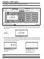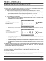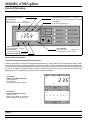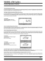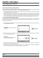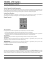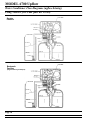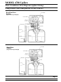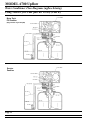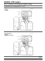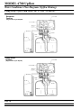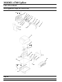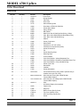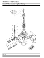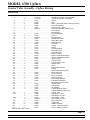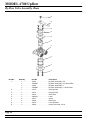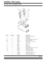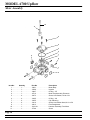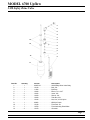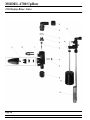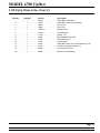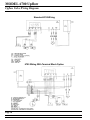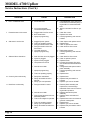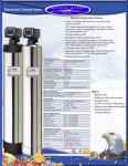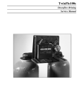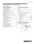
1
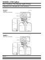
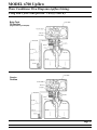
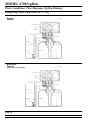
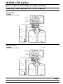
MODEL 6700
Upflow Brining
Service Manual
IMPORTANT: Fill in pertinent information on page 2 for future reference.
MODEL 6700 Upflow
Job Specification Sheet
Job Number ____________________________________________
Model Number __________________________________________
Water Test _____________________________________________
Capacity Of Unit ________________________ Max. _____________ Per Regeneration
Mineral Tank Size: Diameter ___________________ Height _____________________
Under Bedding ____________________________ Amount _______________________
Type Of Media ____________________________ Cubic Feet _____________________
Brine Tank Size __________________________________________________________
Salt Setting Per Regeneration _______________________________________________
Valve Programming
Water Hardness___________________________________
System Capacity __________________________________
Regeneration Time ________________________________
Regeneration Cycle Step #1__________________________
Regeneration Cycle Step #2__________________________
Regeneration Cycle Step #3__________________________
Regeneration Cycle Step #4__________________________
Regeneration Cycle Step #5__________________________
Notes:
________________________________________________________________________________
________________________________________________________________________________
________________________________________________________________________________
________________________________________________________________________________
________________________________________________________________________________
________________________________________________________________________________
Page 2
Printed in U.S.A.
MODEL 6700 Upflow
General Residential Installation Check List
WATER PRESSURE: A minimum of 25 pounds of water pressure is required for regeneration valve to operate
effectively.
ELECTRICAL FACILITIES: An uninterrupted alternating current (A/C) supply is required. Please make sure your
voltage supply is compatible with your unit before installation.
EXISTING PLUMBING: Condition of existing plumbing should be free from lime and iron buildup. Piping that is built up
heavily with line and/or iron should be replaced. If piping is clogged with iron, a separate iron filter unit should be
installed ahead of the water softener.
LOCATION OF SOFTENER AND DRAIN: The softener should be located close to a clean working drain and
connected according to local plumbing codes.
BY-PASS VALVES: Always provide for the installation of a by-pass valve if unit is not equipped with one.
CAUTION: Water pressure is not to exceed 120 p.s.i., water temperature is not to exceed 110°F, and the unit cannot be
subjected to freezing conditions.
Installation And Start-Up Procedures
1. Place the softener tank where you want to install the unit, making sure the tanks are level and on a firm base.
2. During cold weather it is recommended that the installer warm the valve up to room temperature before operating.
3. All plumbing should be done in accordance with local plumbing codes. The pipe size for the drain should be a
minimum of 1/2″. Backwash flow rates in excess of 7 gpm or length in excess of 20´ require 3/4″ drain line.
4. The 1″ distributor tube (1.050 O.D.) should be cut 2.00″ below the top of each tank. Note: Only use silicone
lubricant.
5. Lubricate the distributor o-ring seal and tank O-ring seal. Place the main control valve on tank.
6. Solder joints near the drain must be done prior to connecting the Drain Line Flow Control fitting (DLFC). Leave at
least 6″ between the DLFC and solder joints when soldering pipes that are connected on the DLFC. Failure to do
this could cause interior damage to DLFC.
7. Teflon tape is the only sealant to be used on the drain fitting.
8. Make sure that the floor is clean beneath the salt storage tank and that it is level.
9. Place approximately 1″ of water above the grid plate. If a grid is not utilized, fill to the top of the air check in the salt
tank. Do not add salt to the brine tank at this time.
10. On units with a by-pass, place in by-pass position. Turn on the main water supply. Open a cold soft water tap
nearby and let run a few minutes or until the system is free from foreign material (usually solder) that may have
resulted from the installation. Once clean, close the water tap.
11. Place the by-pass in service position and let water flow into the mineral tank. When water flow stops, slowly open a
cold water tap nearby and let run until the air is purged from the unit.
12. Plug the valve into an approved power source. Once the valve is powered it will drive to the Service Position.
Page 3
Printed in U.S.A.
MODEL 6700 Upflow
Installation and Start-Up Procedures (Cont’d.)
Reserve Indicator:
Volume Remaining Above Reserve
- Arrow Off
Volume Remaining At Or Below Reserve - Arrow Flashing
Time Of Day Display Indicator
Service Indicator:
Valve In Service
- Arrow On
Manual Regeneration Tonight - Flashing Arrow
Flow Indicator:
Arrow Flashes With Water Flow
Regeneration Indicator
Valve In Regeneration - Arrow On
Figure #1
Volume Remaining display Indicator
13. Once the valve has reached Service position normal operation is resumed. In normal operation the Time Of Day,
and if flow meter equipped, Volume Remaining Displays alternate being viewed. Set the Time Of Day Display by
depressing the Up or Down Set Button, to the correct time. (See Fig. 1) Note: Time Of Day must be set correctly to
either A.M. or P.M.
For Example:
12:59 A.M.
(Valve in Service)
14. Flow Meter Equipped Valves Only: The Volume Remaining Display is the volume of water (In gallons) remaining
prior to regeneration, including any reserve capacity. Without any water usage the Meter Arrow should be either off
or on but not changing. Open a soft water tap. The Meter Arrow should begin flashing at a rate that varies with flow
rate. Close the tap after 3-5 gallons of water flow.
For Example:
833 Gallons Of Water Remaining
For Example:
0 Gallons Of Water Remaining
(Valve in Service)
(No water flow)
(Valve in Service)
(Water flowing, Meter Arrow flashing)
(Volume is below reserve capacity)
(Reserve Arrow flashing)
Page 4
Printed in U.S.A.
MODEL 6700 Upflow
Installation And Start-Up Procedures (Cont’d.)
15. Manually initiate a regeneration cycle and allow water to run to drain for 3 to 4 minutes. Next, manually step the
valve through a regeneration cycle checking valve operation in each step.
A. Initiating Regeneration (Depending on the timer regeneration type you have one or two (2) Options):
1. Press and Release the Extra Cycle Button. With Immediate Regeneration Timers the control will go into
regeneration immediately. With Delayed Regeneration Timers the Service Arrow will begin to flash
immediately and a regeneration will occur at the preset regeneration time (i.e. 2:00 a.m.)
2. Press and Hold for 5 seconds the Extra Cycle Button. The control will go into regeneration immediately.
B. Control Operation During Regeneration:
1. During regeneration the control will display the regeneration step number the valve is advancing to, or has
reached, and the time remaining in that step.
For Example:
(Valve is advancing to Regeneration Step #1)
(#1 flashing)
(Regeneration Arrow on)
Backwash
2. When the first cycle step is reached, a red LED will turn on to indicate the current regeneration cycle step.
For Example:
(Regeneration Step #1 has been reached)
(10.0 minutes remain in Step #1)
Backwash
3. Pushing the Extra Cycle Button during a regeneration step will immediately advance the valve to the next
regeneration step position.
4. Pushing Up or Down Set Button during a regeneration step will adjust the time remaining in that current
regeneration step. Programmed Regeneration Steps will not be changed.
5. Once all regeneration cycle steps have been completed the valve will return to service and resume normal
operation.
16. Add water to the brine tank to the top of the air check. Manually step the valve to the Brine Draw position (see Step
#14) and allow the valve to draw water from the brine tank until it stops. Note: The air check will check at
approximately the midpoint of the screened intake area.
17. Manually step the valve to the brine refill position and allow the valve to return to service automatically.
18. Make sure the brine refill time (salt dosage) is set as recommended by the manufacturer.
19. With the valve in service, check that there is about 1″ of water above the grid in the brine tank, if used.
20. Fill the brine tank with salt.
21. A 9V Alkaline Battery is recommended to be installed at all times for proper valve operation. The control will
indicate when the battery needs to be replaced by turning on the Low Battery LED.
Page 5
Printed in U.S.A.
MODEL 6700 Upflow
Control Operation
Reserve Indicator:
Volume Remaining Above Reserve
- Arrow Off
Volume Remaining At Or Below Reserve - Arrow Flashing
Time Of Day Display Indicator
Service Indicator:
Valve In Service
- Arrow On
Manual Regeneration Tonight - Flashing Arrow
Flow Indicator:
Arrow Flashes With Water Flow
Regeneration Indicator
Valve In Regeneration - Arrow On
Sensor Indicator:
Lockout Indicator:
Lockout Signal - Arrow On
Sensor Input Signal
- Flashing Arrow
Valid Regeneration Signal - Arrow On
Volume Remaining Display Indicator
Normal Control Operation
Flow Meter Equipped Delayed Regeneration Valves
In Normal Operation the Time Of Day Display will alternate being viewed with the Volume Remaining Display. Water
flow through the unit is indicated by the Meter Arrow that will flash in a direct relationship to flow rate. As treated water
is used, the Volume Remaining Display will count down from a maximum value to the calculated reserve capacity. Once
this occurs, the Reserve Arrow will begin to flash as a indication that reserve capacity is being used. At the preset
Regeneration Time a regeneration cycle will then be initiated immediately.
For Example:
235 Gallons Of Water Remaining
(Valve in Service)
(No water flow)
(Volume is below reserve capacity)
For Example:
0 Gallons Of Water Remaining
(Valve in Service)
(Water Flowing, Meter Arrow Flashing)
(Volume is below reserve capacity)
Page 6
Printed in U.S.A.
MODEL 6700 Upflow
Control Operation (Cont’d.)
Timeclock Regeneration Valves
In Normal Operation the Time Of Day Display will be viewed at all times. The control will operate normally until the days
since the last regeneration reaches the preset number of days. Once this occurs, a regeneration cycle will then be
initiated immediately at the preset Regeneration Time.
Flow Meter Equipped Immediate Regeneration Valves
In Normal Operation the Time Of Day Display will alternate being viewed with the Volume Remaining Display. Water
flow through the unit is indicated by the Meter Arrow that will flash in a direct relationship to flow rate. As treated water
is used, the Volume Remaining Display will count down from a maximum value to zero. Once this occurs a regeneration
cycle will then be initiated immediately.
For Example:
525 Gallons Of Water Remaining
(Valve In Service)
(Water Flowing, Meter Arrow Flashing)
Sensor Immediate Regeneration Valves
In Normal Operation the Time Of Day Display will be viewed at all times. The control will operate normally until a valid
sensor input signal is received. Once this occurs, a regeneration cycle will then be initiated immediately. The Sensor
Input Arrow will flash until the signal is determined to be valid.
Sensor Delayed Regeneration Valves
In Normal Operation the Time Of Day Display will be viewed at all times. The control will operate normally until a valid
sensor input signal is received. Once this occurs, a regeneration cycle will then be initiated immediately at the preset
Regeneration Time. The Sensor Input Arrow will flash until the signal is determined to be valid. Then the Reserve
Arrow will begin to flash as a indication that reserve capacity is being used.
For Example:
12:58 P.M. With Invalid Sensor Signal
(Valve In Service)
(Sensor Arrow Flashing)
For Example:
12:59 P.M. With Valid Sensor Signal
(Valve In Service)
(Sensor Arrow On)
(Reserve arrow flashing) (Delayed Regen)
Immediate Regeneration Valves With Days Between Regeneration Override Set
When the valve reaches its set Days Since Regeneration Override value a regeneration cycle will be initiated
immediately. This event occurs regardless of the Volume Remaining display having reached zero.
Delayed Regeneration Valves With Days Between Regeneration Override Set
When the valve reaches its set Days Since Regeneration Override value a regeneration cycle will be initiated at the
preset Regeneration Time. This event occurs regardless of the Volume Remaining display having reached the
calculated reserve capacity.
Page 7
Printed in U.S.A.
MODEL 6700 Upflow
Control Operation (Cont’d.)
Control Operation During A Power Failure
During a power failure all control displays will be turned off and regeneration cycles delayed. The control will otherwise
continue to operate normally until line power is restored or battery backup power is lost.
1. If battery backup power is never lost during a power outage, the control will continue to operate normally, without
the loss of data, until line power is restored.
2. If battery backup power is lost during a power outage, the control will store the current Time Of Day, Volume
Remaining, Regeneration Cycle Status, and various diagnostic displays. These stored displays will then be used
upon line power restoration until updated ones are created. To indicate this type of failure, the control will flash the
current Time Of Day Display to indicate that this display and the Volume Remaining Display may not be correct.
Control Operation During Regeneration
In regeneration the control will display what regeneration step number the valve is advancing to, or has reached, and
the time remaining in that step. Once all regeneration cycle steps have been completed the valve will return to service
and resume normal operation.
1. First the Regeneration Arrow turns on. Then the display below is viewed to indicate that the valve is advancing to
the first regeneration cycle step.
For Example:
(Valve is advancing to Regeneration Step #1)
(#1 flashing)
Backwash
2. When the first cycle step is reached, the display becomes as shown below. A red LED will also turn on to indicate
the current regeneration cycle step.
For Example:
(Regeneration Step #1 has been reached)
(10.0 minutes remain in Step #1)
Backwash
3. Pushing the Extra Cycle Button during a regeneration cycle will immediately advance the valve to the next cycle
step position and resume normal step timing.
4. Pushing the Up or Down Set Button during a regeneration cycle will adjust the time remaining in a regeneration
cycle step. Actual Regeneration Cycle Step programming will not be changed.
Page 8
Printed in U.S.A.
MODEL 6700 Upflow
Control Operation (Cont’d.)
Control Operation During Programming
The control will only enter the Program Mode with the valve in Service and operating on line power. While in the
Program Mode the control will continue to operate normally monitoring water usage and keeping all displays up to date.
Control programming is stored in memory permanently with or without line or battery backup power.
Lockout Input Operation
The Lockout Arrow will turn on whenever a Lockout Signal is being received by the control. Any requests for
regeneration will be delayed until this signal is removed. Regeneration will then proceed normally.
Keypad Operation
Extra Cycle Button
Pushing this button will initiate a regeneration cycle independently of actual valve conditions.
1. With immediate regeneration valves this extra regeneration would occur immediately.
2. With delayed regeneration valves this extra regeneration would occur at the set Regeneration Time. A regeneration
cycle can be forced to occur immediately by pushing and holding in for 5 seconds this button.
Program Button
This button is used by the installer to program those settings indicated on the front panel by red LEDs.
Up Set Button
This button is used to set the current time of day, adjust time remaining in a regeneration cycle step, and in valve
programming. The Up Arrow Button will increment a display setting.
Down Set Button
This button is used to set the current time of day, adjust time remaining in a regeneration cycle step, and in valve
programming. The Down Arrow Button will decrement a display setting.
Low Battery Indicator
When the control is operating on line power this red LED will turn on whenever the 9V Alkaline Battery (Not Included)
used for memory backup needs to be replaced. The battery is stored inside the top cover. In the event of a power
outage, the battery will maintain current operating data for approximately 24 hours at maximum battery capacity.
Page 9
Printed in U.S.A.
MODEL 6700 Upflow
Water Conditioner Flow Diagrams (upflow brining)
Using Yellow Cycle Cam (part no. 24598)
Service
Position
Backwash
Position
(Regeneration Cycle Step #1)
Page 10
Printed in U.S.A.
MODEL 6700 Upflow
Water Conditioner Flow Diagrams (upflow brining)
Using Yellow Cycle Cam (part no. 24598) (Cont’d.)
Brine/Slow Rinse
Position
(Regeneration Cycle Step #2)
Rapid Rinse
Position
(Regeneration Cycle Step #3)
Page 11
Printed in U.S.A.
MODEL 6700 Upflow
Water Conditioner Flow Diagrams (upflow brining)
Using Yellow Cycle Cam (part no. 24598) (Cont’d.)
Brine Tank
Fill Position
(Regeneration Cycle Step #4)
Service
Position
Page 12
Printed in U.S.A.
MODEL 6700 Upflow
Water Conditioner Flow Diagrams (upflow brining)
Using Red Cycle Cam (part no. 17885)
Service
Position
Brine/Slow Rinse
Position
(Regeneration Cycle Step #1)
Page 13
Printed in U.S.A.
MODEL 6700 Upflow
Water Conditioner Flow Diagrams (upflow brining)
Using Red Cycle Cam (part no. 17885) (Cont’d.)
Backwash
Position
(Regeneration Cycle Step #2)
Rapid Rinse
Position
(Regeneration Cycle Step #3)
Page 14
Printed in U.S.A.
MODEL 6700 Upflow
Water Conditioner Flow Diagrams (upflow brining)
Using Red Cycle Cam (part no. 17885) (Cont’d.)
Brine Tank
Fill Position
(Regeneration Cycle Step #4)
Service
Position
Page 15
Printed in U.S.A.
MODEL 6700 Upflow
Water Conditioner Flow Diagrams (Upflow Brining)
Using Gray Cycle Cam (Part No. 17919)
Service
Position
Brine Refill
Position
(Regeneration Cycle Step #1)
Page 16
Printed in U.S.A.
MODEL 6700 Upflow
Water Conditioner Flow Diagrams (Upflow Brining)
Using Gray Cycle Cam (Part No. 17919) - (Cont’d.)
Brine Making
Position
(Regeneration Cycle Step #2)
Brine/Slow Rinse
Position
(Regeneration Cycle Step #3)
Page 17
Printed in U.S.A.
MODEL 6700 Upflow
Water Conditioner Flow Diagrams (Upflow Brining)
Using Gray Cycle Cam (Part No. 17919) - (Cont’d.)
Backwash
Position
(Regeneration Cycle Step #4)
Rapid Rinse
Position
(Regeneration Cycle Step #5)
Page 18
Printed in U.S.A.
MODEL 6700 Upflow
Notes
Page 19
Printed in U.S.A.
MODEL 6700 Upflow
Valve Powerhead
(See Opposite Page for Parts List)
16
1
2
8
9
3
4
5
13
6
7
11
12
36
14
10
15
34
17
18
19
20
21
27
23
24
1
25
26
29
22
30
28
31
32
33
Page 20
Printed in U.S.A.
MODEL 6700 Upflow
Valve Powerhead
Parts List
Item No.
Quantity
1. . . . . . . . . . . 1 . . . . . . . . . . .
2. . . . . . . . . . . 1 . . . . . . . . . . .
3. . . . . . . . . . . 1 . . . . . . . . . . .
4. . . . . . . . . . . 1 . . . . . . . . . . .
5. . . . . . . . . . . 1 . . . . . . . . . . .
6. . . . . . . . . . . 1 . . . . . . . . . . .
7. . . . . . . . . . . 3 . . . . . . . . . . .
8. . . . . . . . . . . 2 . . . . . . . . . . .
9. . . . . . . . . . . 2 . . . . . . . . . . .
10 . . . . . . . . . . 1 . . . . . . . . . . .
11 . . . . . . . . . . 1 . . . . . . . . . . .
12
13
14
15
..........
..........
..........
..........
16
17
18
19
20
21
..........
..........
..........
..........
..........
..........
22
23
24
25
26
..........
..........
..........
..........
..........
27 . . . . . . . . . .
28 . . . . . . . . . .
29
30
31
32
33
34
35
36
..........
..........
..........
..........
..........
..........
..........
..........
Part No.
Description
14193-03 . . . . . . . . . . Drive Panel
13299 . . . . . . . . . . . . Spring Washer
13017 . . . . . . . . . . . . Idler Gear
23045 . . . . . . . . . . . . Drive Gear
13175 . . . . . . . . . . . . Motor Mounting Plate
16944 . . . . . . . . . . . . Drive Motor 2 RPM 24V 50/60 Hz
11384 . . . . . . . . . . . . Screw, Motor Mount
19080 . . . . . . . . . . . . Spring, Detent
13300 . . . . . . . . . . . . Ball, Detent
24958 . . . . . . . . . . . . Main Drive Gear & Shaft (Upflow Brining - White)
18722 . . . . . . . . . . . . Cam, Brine Valve (Backwash and Brine/Rinse First)
19025 . . . . . . . . . . . . Cam, Brine Valve (Variable Brining)
1 . . . . . . . . . . . 12037 . . . . . . . . . . . . Washer
2 . . . . . . . . . . . 13296 . . . . . . . . . . . . Screw, Component
1 . . . . . . . . . . . 13547 . . . . . . . . . . . . Strain Relief
1 . . . . . . . . . . . 19674 . . . . . . . . . . . . Transformer, U.S. 24V (120V)
25651 . . . . . . . . . . . . Transformer, European 24V (230V)
2 . . . . . . . . . . . 12473 . . . . . . . . . . . . Screw, Drive Mount
2 . . . . . . . . . . . 18754 . . . . . . . . . . . . Pin
4 . . . . . . . . . . . 17798 . . . . . . . . . . . . Screw, Mounting Plate
1 . . . . . . . . . . . 17844 . . . . . . . . . . . . Mounting Plate
1 . . . . . . . . . . . 19079 . . . . . . . . . . . . Friction Washer
1 . . . . . . . . . . . 24598 . . . . . . . . . . . . Cycle Cam (Upflow - Yellow) Backwash First
1 . . . . . . . . . . . 17885 . . . . . . . . . . . . Cycle Cam (Upflow - Red) Brine Draw/Slow Rinse First
1 . . . . . . . . . . . 17919 . . . . . . . . . . . . Cycle Cam (Upflow - Grey) Variable Brining
1 . . . . . . . . . . . 15151 . . . . . . . . . . . . Screw, Cycle Cam
2 . . . . . . . . . . . 10218 . . . . . . . . . . . . Microswitch
1 . . . . . . . . . . . 10302 . . . . . . . . . . . . Insulator
2 . . . . . . . . . . . 17876 . . . . . . . . . . . . Screw, Microswitch
1 . . . . . . . . . . . 19313-XXX . . . . . . . . Circuit Board Housing Assy. (State if optional relay is
installed, and cycle cam color)
1 . . . . . . . . . . . . 40042-01/40042-02 . . Wire Harness, Power (Std. 6700/6700 with
Terminal Block Option)
1 . . . . . . . . . . . . 19119-01/40041-02 . . Wire Harness, Low Voltage (Std. 6700/6700 with
Terminal Block Option)
1 . . . . . . . . . . . 18615-01 . . . . . . . . . . Seal
1 . . . . . . . . . . . . . . . . . . . . . . . . . . . . . 9V Alkaline Battery (Not Included)
1 . . . . . . . . . . . 18679 . . . . . . . . . . . . Tapered Cap
1 . . . . . . . . . . . 17845 . . . . . . . . . . . . Hinge Pin
1 . . . . . . . . . . . 17841-xx . . . . . . . . . . Bottom Cover (Specify Color)
1 . . . . . . . . . . . 17842-xx . . . . . . . . . . Top Cover (Specify Color)
4 . . . . . . . . . . . 12681 . . . . . . . . . . . . Wire Nut, Beige (Not Shown)
1 . . . . . . . . . . . 40214 . . . . . . . . . . . . Screw
Page 21
Printed in U.S.A.
MODEL 6700 Upflow
Control Valve Assembly - Upflow Brining
11
10
7
6
5
4
3
12
2
13
14
15
16
17
1
18
58
57
17
59
51
20
56
26
58
22
49
00
48 47
23
28
46
45
29
25
24
40
41
52
39
42
53
43
31
44
55
Page 22
Printed in U.S.A.
54B
54A
MODEL 6700 Upflow
Control Valve Assembly - Upflow Brining
Parts List
Item No.
Quantity
Part No.
Description
1 . . . . . . . . . . . 1 . . . . . . . . . . . . 17703-20 . . . . . . . . . . . . . . Valve Body, Up-Flow 13/16″ Distributor
1 . . . . . . . . . . . . 17703-10 . . . . . . . . . . . . . . Valve Body, Up-Flow 1″ Distributor
2 . . . . . . . . . . . 4 . . . . . . . . . . . . 14241 . . . . . . . . . . . . . . . . . Spacer
3 . . . . . . . . . . . 5 . . . . . . . . . . . . 13242 . . . . . . . . . . . . . . . . . Seal
4 . . . . . . . . . . . 1 . . . . . . . . . . . . 18848 . . . . . . . . . . . . . . . . . Piston - (Used with Yellow or Red Cycle Cam)
5 . . . . . . . . . . . 1 . . . . . . . . . . . . 14309 . . . . . . . . . . . . . . . . . Piston Rod Retainer
6 . . . . . . . . . . . 1 . . . . . . . . . . . . 15561 . . . . . . . . . . . . . . . . . End Plug Assy - White
7 . . . . . . . . . . . 1 . . . . . . . . . . . . 13001-03 . . . . . . . . . . . . . . Piston Rod Assembly, 6600 Up Flow
8 . . . . . . . . . . . . . . . . . . . . . . . . . . . . . . . . . . . . . . . . . . . . . . . . Not Assigned
9 . . . . . . . . . . . . . . . . . . . . . . . . . . . . . . . . . . . . . . . . . . . . . . . . Not Assigned
10 . . . . . . . . . . . 1 . . . . . . . . . . . . 13546 . . . . . . . . . . . . . . . . . End Plug Retainer
11 . . . . . . . . . . . 3 . . . . . . . . . . . . 12473 . . . . . . . . . . . . . . . . . Screw
12 . . . . . . . . . . . 1 . . . . . . . . . . . . 11981-01 . . . . . . . . . . . . . . Retaining Ring
13 . . . . . . . . . . . 1 . . . . . . . . . . . . 16098 . . . . . . . . . . . . . . . . . Washer Brine Valve
14 . . . . . . . . . . . 1 . . . . . . . . . . . . 11973 . . . . . . . . . . . . . . . . . Spring Brine Valve
15 . . . . . . . . . . . 1 . . . . . . . . . . . . 13165 . . . . . . . . . . . . . . . . . Brine Valve Cap
16 . . . . . . . . . . . 1 . . . . . . . . . . . . 12550 . . . . . . . . . . . . . . . . . Quad Ring
17 . . . . . . . . . . . 2 . . . . . . . . . . . . 13302 . . . . . . . . . . . . . . . . . O-Ring
18 . . . . . . . . . . . 1 . . . . . . . . . . . . 13167 . . . . . . . . . . . . . . . . . Spacer
19 . . . . . . . . . . . 1 . . . . . . . . . . . . 14613 . . . . . . . . . . . . . . . . . Flow Straightener
20 . . . . . . . . . . . 1 . . . . . . . . . . . . 13172 . . . . . . . . . . . . . . . . . Brine Valve Stem
21 . . . . . . . . . . . 1 . . . . . . . . . . . . 12626 . . . . . . . . . . . . . . . . . Brine Valve Seat
22 . . . . . . . . . . . 1 . . . . . . . . . . . . 13163 . . . . . . . . . . . . . . . . . Injector Housing
23 . . . . . . . . . . . 1 . . . . . . . . . . . . 10913 . . . . . . . . . . . . . . . . . Injector Nozzle (Specify Size)
24 . . . . . . . . . . . 1 . . . . . . . . . . . . 10914 . . . . . . . . . . . . . . . . . Injector Throat (Specify Size)
25 . . . . . . . . . . . 1 . . . . . . . . . . . . 10227 . . . . . . . . . . . . . . . . . Injector Screen
26 . . . . . . . . . . . 2 . . . . . . . . . . . . 13301 . . . . . . . . . . . . . . . . . O-Ring Injector
28 . . . . . . . . . . . 1 . . . . . . . . . . . . 13303 . . . . . . . . . . . . . . . . . O-Ring Injector Cover
29 . . . . . . . . . . . 1 . . . . . . . . . . . . 13166 . . . . . . . . . . . . . . . . . Injector Cover
31 . . . . . . . . . . . 2 . . . . . . . . . . . . 13315 . . . . . . . . . . . . . . . . . Screw
39 . . . . . . . . . . . 1 . . . . . . . . . . . . 13245 . . . . . . . . . . . . . . . . . BLFC Button Retainer
40 . . . . . . . . . . . 1 . . . . . . . . . . . . 12977 . . . . . . . . . . . . . . . . . O-Ring
41 . . . . . . . . . . . 1 . . . . . . . . . . . . . . . . . . . . . . . . . . . . . . . . . . . BLFC Button (Specify Size)
42 . . . . . . . . . . . 1 . . . . . . . . . . . . 13244 . . . . . . . . . . . . . . . . . BLFC Fitting 3/8″
43 . . . . . . . . . . . 3 . . . . . . . . . . . . 10332 . . . . . . . . . . . . . . . . . BLFC Insert 3/8″
44 . . . . . . . . . . . 3 . . . . . . . . . . . . 10330 . . . . . . . . . . . . . . . . . BLFC Ferrule 3/8″
45 . . . . . . . . . . . 1 . . . . . . . . . . . . 13308 . . . . . . . . . . . . . . . . . Drain Hose Barb
46 . . . . . . . . . . . 1 . . . . . . . . . . . . 13173 . . . . . . . . . . . . . . . . . DLFC Button Retainer
47 . . . . . . . . . . . 1 . . . . . . . . . . . . 15348 . . . . . . . . . . . . . . . . . O-Ring DLFC Retainer
48 . . . . . . . . . . . 1 . . . . . . . . . . . . . . . . . . . . . . . . . . . . . . . . . . . DLFC Button (Specify Size)
49 . . . . . . . . . . . 1 . . . . . . . . . . . . 13333 . . . . . . . . . . . . . . . . . Injector Label
50 . . . . . . . . . . . 1 . . . . . . . . . . . . 12638 . . . . . . . . . . . . . . . . . O-Ring Drain
51 . . . . . . . . . . . 1 . . . . . . . . . . . . 13497 . . . . . . . . . . . . . . . . . Air Disperser
52 . . . . . . . . . . . 1 . . . . . . . . . . . . 13304 . . . . . . . . . . . . . . . . . O-Ring Distributor Tube 1″
10244 . . . . . . . . . . . . . . . . . O-Ring Distributor Tube 13/16″
53 . . . . . . . . . . . 1 . . . . . . . . . . . . 12281 . . . . . . . . . . . . . . . . . O-Ring, -338
54A . . . . . . . . . . 1 . . . . . . . . . . . . 13398 . . . . . . . . . . . . . . . . . Yoke, Brass, 1″ NPT
1 . . . . . . . . . . . . 13708 . . . . . . . . . . . . . . . . . Yoke, Brass, 3/4″ NPT
54B . . . . . . . . . . 1 . . . . . . . . . . . . 18706 . . . . . . . . . . . . . . . . . Yoke, Plastic, 1″ NPT
1 . . . . . . . . . . . . 13706-02 . . . . . . . . . . . . . . Yoke, Plastic, 3/4″ NPT
55 . . . . . . . . . . . 3 . . . . . . . . . . . . 10329 . . . . . . . . . . . . . . . . . BLFC Fitting Nut
*56 . . . . . . . . . . . 2 . . . . . . . . . . . . 13255 . . . . . . . . . . . . . . . . . Adapter Clip
*57 . . . . . . . . . . . 2 . . . . . . . . . . . . 19228 . . . . . . . . . . . . . . . . . Adapter Coupling
*58 . . . . . . . . . . . 4 . . . . . . . . . . . . 13305 . . . . . . . . . . . . . . . . . O-Ring - Adapter Coupling
*59 . . . . . . . . . . . 2 . . . . . . . . . . . . 13314 . . . . . . . . . . . . . . . . . Screw - Adapter Coupling
*Not used with meter controls.
Page 23
Printed in U.S.A.
MODEL 6700 Upflow
By-Pass Valve Assembly, Brass
9
8
6
5
4
3
1
2
7
6
Item No.
Quantity
Part No.
Description
1 . . . . . . . . . . . 1. . . . . . . . . . . . 17290. . . . . . . . . . . . . . . . By-Pass Valve Body, 3/4″
1. . . . . . . . . . . . 17290NP . . . . . . . . . . . . . By-Pass Valve Body, 3/4″ Nickel Plate
1. . . . . . . . . . . . 13399. . . . . . . . . . . . . . . . By-Pass Valve Body, 1″
1. . . . . . . . . . . . 13399NP . . . . . . . . . . . . . By-Pass Valve Body, 1″, Nickel Plate
2 . . . . . . . . . . . 1. . . . . . . . . . . . 11726. . . . . . . . . . . . . . . . Seal, By-Pass
3 . . . . . . . . . . . 1. . . . . . . . . . . . 11972. . . . . . . . . . . . . . . . Plug, By-Pass
4 . . . . . . . . . . . 1. . . . . . . . . . . . 11978. . . . . . . . . . . . . . . . Side Cover
5 . . . . . . . . . . . 1. . . . . . . . . . . . 13604-01 . . . . . . . . . . . . . Label
6 . . . . . . . . . . . 8. . . . . . . . . . . . 15727. . . . . . . . . . . . . . . . Screw
7 . . . . . . . . . . . 1. . . . . . . . . . . . 11986. . . . . . . . . . . . . . . . Side Cover
8 . . . . . . . . . . . 1. . . . . . . . . . . . 11979. . . . . . . . . . . . . . . . Lever, By-Pass
9 . . . . . . . . . . . 1. . . . . . . . . . . . 11989. . . . . . . . . . . . . . . . Screw, Hex Head, 1/4-14
Page 24
Printed in U.S.A.
MODEL 6700 Upflow
By-Pass Valve Assembly, Plastic
5A
8
5B
6
7
1
2
3
4
11
10
9
12A
12B
Item No.
Quantity
1. . . . . . . . . . . 1 . . . . . . . . . . .
2. . . . . . . . . . . 1 . . . . . . . . . . .
3. . . . . . . . . . . 1 . . . . . . . . . . .
4. . . . . . . . . . . 2 . . . . . . . . . . .
5A . . . . . . . . . . 1 . . . . . . . . . . .
5B . . . . . . . . . . 1 . . . . . . . . . . .
6. . . . . . . . . . . 4 . . . . . . . . . . .
7. . . . . . . . . . . 2 . . . . . . . . . . .
8. . . . . . . . . . . 2 . . . . . . . . . . .
9. . . . . . . . . . . 2 . . . . . . . . . . .
10 . . . . . . . . . . 2 . . . . . . . . . . .
11 . . . . . . . . . . 2 . . . . . . . . . . .
12A . . . . . . . . . 1 . . . . . . . . . . .
12B . . . . . . . . .
...........
...........
...........
1
1
1
1
...........
...........
...........
...........
Part No.
17819 . . . . . . . . . . . . . . .
11183 . . . . . . . . . . . . . . .
18582 . . . . . . . . . . . . . . .
17512 . . . . . . . . . . . . . . .
17820 . . . . . . . . . . . . . . .
17820-01 . . . . . . . . . . . . .
18661 . . . . . . . . . . . . . . .
18662 . . . . . . . . . . . . . . .
18660 . . . . . . . . . . . . . . .
13305 . . . . . . . . . . . . . . .
13255 . . . . . . . . . . . . . . .
13314 . . . . . . . . . . . . . . .
18706 . . . . . . . . . . . . . . .
18706-02 . . . . . . . . . . . . .
13708 . . . . . . . . . . . . . . .
13708NP . . . . . . . . . . . . .
13398 . . . . . . . . . . . . . . .
13398NP . . . . . . . . . . . . .
Description
By-Pass Valve Body, Plastic
O Ring, -015
Cap, By-Pass
Screw, Hex Washer Head, #6-24 x 3
Plug, By-Pass, Inlet
Plug, By-Pass, Outlet (White)
O Ring, -218
Retaining Ring
O Ring
O Ring, -119
Clip, Mounting
Screw, Hex Washer Head, 8-18 x 5/8
Yoke, Plastic, 1″ NPT
Yoke, Plastic, 3/4″ NPT
Yoke, Brass, 3/4″ NPT
Yoke, 3/4″ NPT Nickel Plated
Yoke, Brass, 1″ NPT
Yoke, 1″ NPT Nickel Plated
Page 25
Printed in U.S.A.
MODEL 6700 Upflow
Meter Assembly
10
11
5
4
3
2
1
9
8
7
6
Item No.
Quantity
Part No.
Description
1 . . . . . . . . . . . 1. . . . . . . . . . . . 13821. . . . . . . . . . . . . . . . Meter Body
2 . . . . . . . . . . . 1. . . . . . . . . . . . 13509. . . . . . . . . . . . . . . . Impeller
3 . . . . . . . . . . . 1. . . . . . . . . . . . 13847. . . . . . . . . . . . . . . . O Ring, -137
4 . . . . . . . . . . . 1. . . . . . . . . . . . 14716. . . . . . . . . . . . . . . . Meter Cap Assembly, Electronic
5 . . . . . . . . . . . 4. . . . . . . . . . . . 12473. . . . . . . . . . . . . . . . Screw, Hex Washer, 10-24 x 5/8
6 . . . . . . . . . . . 4. . . . . . . . . . . . 13305. . . . . . . . . . . . . . . . O Ring, -119
7 . . . . . . . . . . . 4. . . . . . . . . . . . 13255. . . . . . . . . . . . . . . . Clip, Mounting
8 . . . . . . . . . . . 4. . . . . . . . . . . . 13314. . . . . . . . . . . . . . . . Screw, Hex Washer Head, 8-18 x 5/8
9 . . . . . . . . . . . 1. . . . . . . . . . . . 14613. . . . . . . . . . . . . . . . Flow Straightener
10. . . . . . . . . . . 1. . . . . . . . . . . . 19121-01 . . . . . . . . . . . . . Harness Assembly, Flow Meter
11. . . . . . . . . . . 1. . . . . . . . . . . . 17798. . . . . . . . . . . . . . . . Screw
Page 26
Printed in U.S.A.
MODEL 6700 Upflow
2300 Safety Brine Valve
7
6
5
4
3
12
2
1
10
8
5
6
7
12
9
11
Item No.
Quantity
1. . . . . . . . . . . 1 . . . . . . . . . . .
2. . . . . . . . . . . 1 . . . . . . . . . . .
3. . . . . . . . . . . 1 . . . . . . . . . . .
4. . . . . . . . . . . 1 . . . . . . . . . . .
5. . . . . . . . . . . 2 . . . . . . . . . . .
6. . . . . . . . . . . 2 . . . . . . . . . . .
7. . . . . . . . . . . 2 . . . . . . . . . . .
8. . . . . . . . . . . 1 . . . . . . . . . . .
9. . . . . . . . . . . 1 . . . . . . . . . . .
10 . . . . . . . . . . 1 . . . . . . . . . . .
11 . . . . . . . . . . 1 . . . . . . . . . . .
12 . . . . . . . . . . 4 . . . . . . . . . . .
Part No.
60027-00 . . . . . . . . . . . . .
10138 . . . . . . . . . . . . . . .
11566 . . . . . . . . . . . . . . .
10328 . . . . . . . . . . . . . . .
10332 . . . . . . . . . . . . . . .
10330 . . . . . . . . . . . . . . .
10329 . . . . . . . . . . . . . . .
10186 . . . . . . . . . . . . . . .
60002 . . . . . . . . . . . . . . .
10149 . . . . . . . . . . . . . . .
10700 . . . . . . . . . . . . . . .
10150 . . . . . . . . . . . . . . .
Description
2300 Safety Brine Valve Body
Ball, 3/8″
Bull Stop
Elbow, 1/4 x 1/4 T
Insert, 3/8″
Sleeve, 3/8″
Tube Nut, 3/8″
Nut, Hex, 10-32, Nylon
#500 Air Check
Float Rod, 30″
Float Assembly, Blue/White
Grommet
Page 27
Printed in U.S.A.
MODEL 6700 Upflow
2310 Safety Brine Valve
Page 28
Printed in U.S.A.
MODEL 6700 Upflow
2310 Safety Brine Valve (Cont’d.)
Item No.
Quantity
1. . . . . . . . . . . 1 . . . . . . . . . . .
2. . . . . . . . . . . 1 . . . . . . . . . . .
3. . . . . . . . . . . 1 . . . . . . . . . . .
4. . . . . . . . . . . 1 . . . . . . . . . . .
5. . . . . . . . . . . 1 . . . . . . . . . . .
6. . . . . . . . . . . 1 . . . . . . . . . . .
7. . . . . . . . . . . 1 . . . . . . . . . . .
8. . . . . . . . . . . 1 . . . . . . . . . . .
9. . . . . . . . . . . 2 . . . . . . . . . . .
10 . . . . . . . . . . 1 . . . . . . . . . . .
11 . . . . . . . . . . 1 . . . . . . . . . . .
12 . . . . . . . . . . 2 . . . . . . . . . . .
13 . . . . . . . . . . 1 . . . . . . . . . . .
14 . . . . . . . . . . 1 . . . . . . . . . . .
Part No.
19645 . . . . . . . . . . . . . . .
19803 . . . . . . . . . . . . . . .
19804 . . . . . . . . . . . . . . .
19805 . . . . . . . . . . . . . . .
19652-01 . . . . . . . . . . . . .
19649 . . . . . . . . . . . . . . .
11183 . . . . . . . . . . . . . . .
19647 . . . . . . . . . . . . . . .
19625 . . . . . . . . . . . . . . .
18312 . . . . . . . . . . . . . . .
60014 . . . . . . . . . . . . . . .
10150 . . . . . . . . . . . . . . .
60068 . . . . . . . . . . . . . . .
60002 . . . . . . . . . . . . . . .
Description
Safety Brine Valve Body
Safety Brine Valve Arm Assembly
Stud, 10-24
Nut, 10-24
Poppet & Seal
Flow Dispenser
O-Ring, -017
Elbow, Safety Brine Valve
Nut Assembly, 3/8
Retaining Clip
Safety Brine Valve, 2310 (includes items 1-10)
Grommet (included with item 13)
Float Assembly, 2310
500 Air Check Assembly
Page 29
Printed in U.S.A.
MODEL 6700 Upflow
Upflow Valve Wiring Diagram
Standard 6700 Wiring
6700 Wiring With Terminal Block Option
Page 30
Printed in U.S.A.
MODEL 6700 Upflow
Service Instructions
A. TO REPLACE TIME BRINE VALVE, INJECTORS, AND
SCREEN
11. Check for leaks at all seal areas. Check drain seal with
the control in the backwash position.
1.
Turn off water supply to conditioner:
12. Plug electrical cord into outlet.
a.
If the conditioner installation has a “three valve” bypass system, first open the valve in the by-pass line,
then close the valves at the conditioner inlet and
outlet.
13. Set time of day and cycle the control valve manually to
assure proper function. Make sure control valve is
returned to the service position.
b.
If the conditioner has an integral by-pass valve, put it
in the by-pass position.
c.
If there is only a shut-off valve near the conditioner
inlet, close it.
2.
Relieve water pressure in the conditioner by stepping the
control into the backwash position momentarily. Return
the control to the service position.
3.
Unplug electrical cord from outlet.
4.
Disconnect brine tube and drain line connections at the
injector body.
Remove the two injector body mounting screws. The
injector and brine module can now be removed from the
control valve. Remove and discard brine body O-rings.
6A. To replace brine valve.
14. Make sure there is enough salt in the brine tank.
15. Start regeneration cycle manually if water is hard.
B. TO REPLACE TIMER
1.
Follow Steps A.1 through A.3.
2.
Remove the control valve back cover. Remove the
control valve front cover. Disconnect the meter
dome signal wire from the front cover and feed it
back through the control.
3.
Remove screw and washer at drive yoke. Remove
timer mounting screws. The entire timer assembly
will now lift off easily.
4.
Put new timer on top of valve. Be sure drive pin on
main gear engages slot in drive yoke.
5.
Replace timer mounting screws. Replace screw and
washer at drive yoke. Replace meter signal wire.
6.
Return by-pass or inlet valving to normal service
position. Water pressure should now be applied to
the conditioner, and any by-pass line shut off.
7.
Replace the control valve back cover.
8.
Follow Steps A.12 through A.15.
5.
1.
Pull brine valve from injector body, also remove and
discard O-ring at bottom of brine valve hole.
2.
Apply silicone lubricant to new O-ring and reinstall
at bottom of brine valve hole.
3.
Apply silicone lubricant to O-ring on new valve
assembly and press into brine valve hole, shoulder
on bushing should be flush with injector body.
6B. To replace injectors and screen.
1.
Remove injector cap and screen, discard O-ring.
Unscrew injector nozzle and throat from injector
body.
2.
Screw in new injector throat nozzle, be sure they are
sealed tightly. Install a new screen.
3.
Apply silicone lubricant to new O-ring and install
around oval extension on injector cap.
7.
Apply silicone lubricant to three new O-rings and install
over three bosses on injector body.
8.
Insert screws with washers thru injector cap and injector.
Place this assembly thru hole in timer housing and into
mating holes in the valve body. Tighten screws.
9.
C. TO REPLACE PISTON ASSEMBLY
1.
Follow Steps A.1 through A.3.
2.
Remove the control valve back cover. Remove the
control valve front cover. Disconnect the meter
dome signal wire from the front cover and feed it
back through the control.
3.
Remove screw and washer at drive yoke. Remove
timer mounting screws. The entire timer assembly
will now lift off easily. Remove end plug retainer
plate.
4.
Pull upward on end of piston yoke until assembly is
out of valve.
5.
Inspect the inside of the valve to make sure that all
spacers and seals are in place, and that there is no
foreign matter that would interfere with the valve
operation.
Reconnect brine tube and drain line.
10. Return by-pass or inlet valving to normal service
position. Water pressure should now be applied to the
conditioner, and any by-pass line shut off.
Page 31
Printed in U.S.A.
MODEL 6700 Upflow
Service Instructions (Cont’d.)
6.
Take new piston assembly as furnished and push
piston into valve by means of the end plug. Twist
yoke carefully in a clockwise direction to properly
align it with drive gear. Replace end plug retainer
plate.
3.
Remove two screws and clips at by-pass valve or
yoke. Pull resin tank away from plumbing
connections.
4.
Remove two screws and clips at control valve. Pull
meter module out of control valve.
7.
Place timer on top of valve. Be sure drive pin on
main gear engages slot in drive yoke.
5.
Apply silicone lubricant to four new O-rings and
assemble to four ports on new meter module.
8.
Replace timer mounting screws. Replace screw and
washer at drive yoke.
6.
9.
Return by-pass or inlet to normal service position.
Water pressure should now be applied to the
conditioner, and any by-pass line shut off.
Assemble meter to control valve. Note: meter
portion of module must be assembled at valve
outlet.
7.
Attach two clips and screws at control valve. Be sure
clip legs are firmly engaged with lugs.
8.
Brush resin tank back to the plumbing connections
and engage meter ports with by-pass valve or yoke.
9.
Attach two clips and screws at by-pass valve or
yoke. Be sure clip legs are firmly engaged with lugs.
10. Replace the control valve back cover.
11. Follow Steps A.12 through A.15.
D. TO REPLACE SEALS AND SPACERS
1.
Follow Steps A.1 through A.3.
2.
Remove the control valve back cover. Remove the
control valve front cover. Disconnect the meter
dome signal wire from the front cover and feed it
back through the control.
3.
4.
5.
6.
7.
8.
9.
Remove screw and washer at drive yoke. Remove
timer mounting screws. The entire timer assembly
will now lift off easily. Remove end plug retainer
plate.
10. Return by-pass or inlet valving to normal service
position. Water pressure should now be applied to
the conditioner, and any by-pass line shut off.
11. Check for leaks at all seal areas.
12. Connect meter dome signal wire.
13. Follow Steps A.12 through A.15.
F.
TO REPLACE METER COVER AND/OR IMPELLER
Pull upward on end of piston rod yoke until
assembly is out of valve. Remove and replace seals
and spacers.
1.
Follow Steps A.1 through A.3.
2.
Remove screw holding signal wire from meter
dome.
Take piston assembly and push piston into valve by
means of the end plug. Twist yoke carefully in a
clockwise direction to properly align it with drive
gear. Replace end plug retainer plate.
3.
Remove four screws on cover.
4.
Lift cover off of meter module, discard O-ring.
5.
Place timer on top of valve. Be sure drive pin on
main gear engages slot in drive yoke.
Remove and inspect impeller for gear or spindle
damage, replace if necessary.
6.
Replace timer mounting screws. Replace screw and
washer at drive yoke.
Apply silicone lubricant to new O-ring and assemble
to the smallest diameter on meter cover.
7.
Return by-pass or inlet valving to normal service
position. Water pressure should now be applied to
the conditioner, and any by-pass line shut off.
Assemble cover to meter module. Be sure impeller
spindle enters freely into cover. Press firmly on
cover and rotate if necessary to assist in assembly.
8.
Replace four screws and tighten.
Replace the control valve back cover.
9.
Return by-pass or inlet valving to normal service
position. Water pressure should now be applied to
the conditioners, and any by-pass shut off.
10. Follow Steps A.12 through A.15.
E. TO REPLACE METER
10. Check for leaks at all seal areas.
1.
Follow Steps A.1 through A.3.
2.
Remove screw holding signal wire from meter
dome.
11. Connect meter dome signal wire.
12. Follow Steps A.12 through A.15.
Page 32
Printed in U.S.A.
MODEL 6700 Upflow
Service Instructions (Cont’d.)
PROBLEM
1.
Softener fails to regenerate.
CAUSE
A. Electrical service to unit has been
interrupted.
B. Timer is not operating properly.
C. Defective valve drive motor.
D. Timer Programming Bad
(Improper programming)
2.
Softener delivers hard water.
A. By-pass valve is open.
B. No salt in brine tank.
C. Injectors or screen plugged.
D. Insufficient water flowing into
brine tank.
E. Hot water tank hardness.
F.
Leak at distributor tube.
G. Internal valve leak
H. Flow meter jammed.
I.
J.
Flow mete cable disconnected or
not plugged into meter cap.
Improper programing.
CORRECTION
A. Assure permanent electrical
service (check fuse, plug, pull chain
or switch).
B. Replace timer.
C. Replace drive motor.
D. Check programming and reset as
needed.
A. Close by-pass valve.
B. Add salt to brine tank and maintain
salt level above water level.
C. Replace injectors and screen.
D. Check brine tank fill time and clean
brine line flow if plugged.
E. Repeated flushings of the hot water
tank is required.
F. Make sure distributor tube is not
cracked. Check O-ring and tube
pilot.
G. Replace seals and spacers and/or
piston.
H. Remove obstruction from flow
meter.
I. Check meter cable connection to
timer and meter cap.
J. Reprogram the control to the proper
regeneration type, inlet water hardness, capacity or flow meter size.
3.
Unit uses too much salt.
A. Improper salt setting.
B. Excessive water in brine tank.
C. Improper programming.
A. Check salt usage and salt setting.
B. See problem No. 7.
C. Check programming and reset as
needed.
4.
Loss of water pressure.
A. Iron buildup in line to water
conditioner.
B. Iron buildup in water conditioner.
A. Clean line to water conditioner.
C. Inlet of control plugged due to
foreign material broken loose from
pipes by recent work done on
plumbing system.
5.
Loss of resin through drain line.
A. Air in water system.
B. Drain line flow control is too large.
B. Clean control and add resin cleaner
to resin bed. Increase frequency of
regeneration.
C. Remove piston and clean control.
A. Assure that well system has proper
air eliminator control check for dry
well condition.
B. Ensure drain line flow control is
sized.
Page 33
Printed in U.S.A.
MODEL 6700 Upflow
Service Instructions (Cont’d.)
PROBLEM
6.
Iron in conditioned water.
CAUSE
A. Fouled resin bed.
B. Iron content exceeds
recommended parameters
CORRECTION
A. Check Backwash, brine draw and
brine tank fill. Increase frequency of
regeneration. Increase backwash
time.
B. Add Iron removal from filter or system.
7.
Excessive water in brine tank.
A. Plugged drain line flow control.
B. Brine valve failure
C. Improper programming.
A. Clean flow control.
B. Replace brine valve
C. Check programming and reset as
needed.
8.
Salt water in service line.
A.
B.
C.
D.
Plugged injector system.
Timer not operating properly.
Foreign material in brine valve.
Foreign material in brine line
flow control.
E. Low water pressure
F. Improper programming.
A.
B.
C.
D.
A.
B.
C.
D.
A.
B.
C.
D.
Clean injector and replace screen.
Replace timer.
Clean or replace brine valve.
Clean brine line flow control.
E. Raise water pressure.
F. Check programming and reset as
needed.
G. Timer not operating properly.
Clean drain line flow control.
Clean or replace injectors.
Replace screen.
Increase line pressure (line pressure must be at least 20 PSI at all
times.)
E. Change seals and spacers and/or
piston assembly.
F. Check programming and reset as
needed.
G. Replace timer.
10. Control cycles continuously.
A. Faulty timer mechanism.
B. Faulty microswitches and or
harness.
C. Faulty cycle cam operation.
A. Replace timer.
B. Replace faulty microswitch or
harness.
C. Replace cycle cam or reinstall.
11. Drain flows continuously.
A. Foreign material in control.
A. Remove piston assembly and
inspect bore, remove foreign
material & check control in various
regeneration positions.
B. Replace seals and/or piston
assembly.
C. Replace piston and seals and
spacers.
D. Replace timer motor and check all
gears for missing teeth.
E. Replace timer.
F. Replace cycle cam or reinstall
G. Replace faulty microswitch and/or
harness.
9.
Softener fails to draw brine.
Drain line flow control is plugged.
Injector is plugged.
Injector screen plugged.
Line pressure is too low.
E. Internal control leak.
F.
Improper programming.
B. Internal control leak.
C. Control valve jammed in brine or
backwash position.
D. Timer motor stopped or jammed.
E. Timer not operating properly.
F. Faulty cycle cam operation
G. Faulty microswitches and/or harness.
Page 34
Printed in U.S.A.
MODEL 6700 Upflow
Service Assemblies
60022-12 . . . . .
60022-25 . . . . .
60022-50 . . . . .
60022-100 . . . .
1 . . . . . . . . . . 17307. . . . . . . .
12094. . . . . . . .
12095. . . . . . . .
12097. . . . . . . .
1 . . . . . . . . . . 12977. . . . . . . .
1 . . . . . . . . . . 13244. . . . . . . .
1 . . . . . . . . . . 13245. . . . . . . .
BLFC .125 GPM
BLFC .25 GPM
BLFC .50 GPM
BLFC 1.0 GPM
For Illustration, See page 22
Flow Washer .125 GPM
Flow Washer .25 GPM
Flow Washer .50 GPM
Flow Washer 1.0 GPM
O-Ring, - 015
Adapter, BLFC
Retainer, BLFC
60032. . . . . . . . Brine Valve
For Illustration, See page 22
1 . . . . . . . . . . 11973. . . . . . . .
1 . . . . . . . . . . 11981-01 . . . . .
1 . . . . . . . . . . 12550. . . . . . . .
1 . . . . . . . . . . 13165. . . . . . . .
1 . . . . . . . . . . 13167. . . . . . . .
2 . . . . . . . . . . 13302. . . . . . . .
1 . . . . . . . . . . 16098. . . . . . . .
1 . . . . . . . . . . 13172. . . . . . . .
1 . . . . . . . . . . 12626. . . . . . . .
60040. . . . . . . .
60040NP . . . . .
60041. . . . . . . .
60041NP . . . . .
Spring, Brine Valve
Retaining Ring
Quad Ring, -009
Cap, Brine Valve
Spacer, Brine Valve
O-Ring, -014
Washer, Plain, Nylon
Brine Valve Stem
Seat, Brine Valve
By Pass, 3/4”, Brass
By Pass, 3/4”, Nickel
By Pass, 1", Brass
By Pass, 1", Nickel
For Illustration and Parts List,
See page 24
60049. . . . . . . . Bypass, Plastic 3/4”
For Illustration, and Parts List,
See page 25
60102-62 . . . . . 6700 Piston Assembly –
Upflow
For Illustration, See page 22
1 . . . . . . . . . . 13001-03 . . . . . Piston Rod Assembly
1 . . . . . . . . . . 14309. . . . . . . . Piston Rod Retainer
1 . . . . . . . . . . 15561. . . . . . . . End Plug Assembly - White
1 . . . . . . . . . . 18848. . . . . . . . Piston
60125. . . . . . . . 6700 Seal and Spacer Kit
For Illustration and Parts List,
See page 22 and page 23
5 . . . . . . . . . . 13242. . . . . . . . Seal
4 . . . . . . . . . . 14241. . . . . . . . Spacer
60084- . . . . . . . Injector Drain Module
Assembly
(Specify Inj. Number, D.L.F.C.
Size, B.L.F.C. Size)
For Illustration and Parts List,
See page 22 and page 23.
60086-50 . . .6700 Meter Assembly
For Illustration and Parts List,
See page 26
19313- . . . . .Assembly, Circuit Board
Housing, 1 Relay
-111 24V Brine Rinse 1st, Black
-112 24V B/W Brine Rinse,
Black
-113 24V Variable Brining,
Black
60341- . . . . .(Specify Voltage)
6700 Metered Power Head
Assembly
Upflow, Brine Rinse 1st, less Cover
-1111 24V 50/60HZ, Black, 1
Relay
60342- . . . . .(Specify Voltage)
6700 Time Clock Power Head
Assembly
Upflow, Brine Rinse 1st, less Cover
-1111 24V 50/60HZ, Black, 1
Relay
60343- . . . . .(Specify Voltage)
6700 Metered Power Head
Assembly
Upflow B/W Brine Rinse, less Cover
-1121 24V 50/60HZ, Black, 1
Relay
60344- . . . . .(Specify Voltage)
6700 Time Clock Power Head
Assembly
Upflow B/W Brine Rinse, less Cover
-1121 24V 50/60HZ, Black, 1
Relay
60345 . . . . . .(Specify Voltage)
6700 Metered Power Head
Assembly
Upflow Variable Brining, less cover
-1131 24V 50/60Hz, Black, 1
Relay
For Illustrations and Parts List
of Power Heads, See page 20 and
page 21.
Page 35
Printed in U.S.A.
P/N 19086
Rev. 2
04/01