1
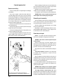
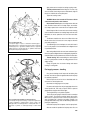
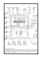
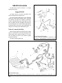
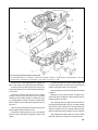
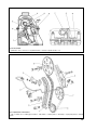
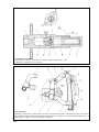
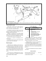
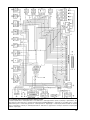
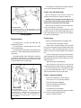
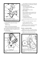
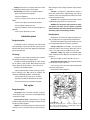
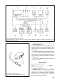
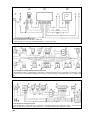
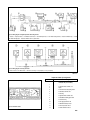
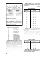
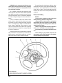
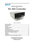
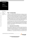
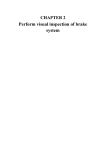
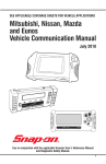
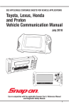
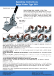
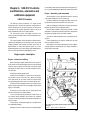
Chapter 9. VAZ-21213 vehicle
modifications, alternative and
additional equipment
VAZ-21214 vehicle
The VAZ-21214 vehicle is fitted with 1.7-L engine, Central
Fuel Injection (CFI). Instead of the carburettor, a single injector is
used for injecting fuel into the central injection unit. Here fuel is
mixed with air, the resulting combustion mixture is fed to the
intake manifold and further to the engine cylinders.
The fuel injection system and catalytic converter in the
exhaust system help reduce exhaust emission and improve vehicle performance.
This chapter provides a brief description of design features,
operation and diagnostics of fuel injection system, removal and
refitting procedures and methods for engine repair. Refer to
Repair Manual for Central Fuel Injection System for a more
detailed description of the system design, repair and diagnostics
with the help of specialized tools and diagnostic charts.
the accelerator cable and check the operation of fuel injection system, as recommended in Repair Manual for Central Fuel Injection.
Engine - dismantling and reassembly
Remove bracket 3 (Fig.9-1) with ignition module 4, then plug
2 with gasket and detent 1 with the sealing ring.
Disconnect and remove the supply/return pipes from the central injection unit and from the bracket on the valve cover.
Undo the retaining pins and remove the central injection unit,
withdraw the gasket from the intake pipe surface.
Remove intake manifold 2 (Fig.9-2) with preheater 1. When
applicable, on a work bench, detach the preheater complete with
the gasket and sealing ring from the intake manifold.
Unscrew the crankshaft position sensor, mounted on the timing cover.
Further dismantling of the engine is carried out in the usual
order as outlined in section 2.
Reassembly is the reversal of dismantling. There is a disposal gasket under the central injection unit, always remember to
renew it during reassembly.
Engine repair - description
Engine - removal and refitting
Before removing the engine, depressurize the fuel system. To
do this, detach the fuel pump wiring plug from the injection wiring
connector, start the engine, run it for a while, then stop the engine
and operate the starter motor for 3 seconds to equalize the pressure in the line.
Disconnect the battery negative lead.
Slacken the nuts holding the air cleaner to the central injection unit and to the pin in the valve cover, detach the relevant
hoses and remove the air cleaner. Detach the injector wiring;
then temporarily plug the filler neck of the central injection unit.
Disconnect the fuel supply/return hoses from the pipes on the
engine. Plug the open ends of the hoses and pipes to prevent dirt
ingress or fuel leaking.
Disconnect the throttle cable from the central injection unit
and from the bracket on the intake manifold.
On the central injection unit disconnect all vacuum hoses to
the charcoal canister and MAP sensor, detach the crankcase
vent hose. Disconnect the wiring from all injection-related units fitted to the engine.
Further steps for removing the engine are in accordance with
the established procedure.
Refitting is the reverse order of removal. On completion adjust
Fig.9-1. Removing the original components from the front left-hand side
of the engine:
1 - detent; 2 - plug; 3 - bracket; 4 - ignition module
185
Central Injection Unit
Removal and refitting
Select the neutral position of the gearchange lever and apply
the handbrake.
Since, after the engine is stalled, fuel remains under pressure, always depressurize the fuel system. To do this, disconnect
the fuel pump wiring plug from the injection wiring harness. Start
the engine and run it until it cuts off. Operate the starter motor for
three seconds to equalize pressure in the pipework. Reconnect
the fuel pump wiring plug to the injection wiring harness.
Disconnect the battery negative lead.
Remove the air cleaner and disconnect the throttle cable from
the central injection unit.
Detach the fuel pipes from the central injection unit and plug
the pipe ends to prevent fuel leakage.
Disconnect the wiring plug (Fig.9-3) of throttle position sensor
4, injector 2 and idle air control valve 9.
On the central injection unit detach the vacuum hoses to the
canister and MAP sender, along with the crankcase vent hose.
Make certain everything is reconnected properly.
Undo the retaining pins and remove the central injection unit
from the intake pipe complete with the gasket. Plug the intake
pipe end to prevent entry of extraneous matter.
Refitting is the reverse order of removing. Pay attention to the
condition of the seals and gaskets, renew if applicable.
On completion, check the fuel pressure as described below.
WARNING. Never re-use the gasket mounted under the
central injection unit and sealing rings of fuel pipes.
Dismantling and reassembly.
Undo the retaining screws and remove throttle position (TP)
sensor 10 (Fig. 9-4), injector 6, fuel pressure regulator, vacuum
hose manifold housing 13 and idle air control valve 14.
Undo two retaining screws and disconnect the fuel supply
part from the throttle housing.
Reassembly is a reverse of dismantling. Examine the seals,
renew if applicable. When refitting the TP sensor, align the throttle shaft flats with the TP sensor pickup lever.
Examination and repair
Injector is a one-piece unit. When removing the injector,
take care not to damage the wiring plug or atomizer head.
WARNING. Never clean or wash the injector with petrol
or other cleaners.
Renew the injector seals. In the event of deposits on the
injector filters (the major diameter filter is a purge filter, while the
minor diameter filter is an intake filter), blow the filters with compressed air, then flush the fuel tank and fuel pipes.
Apply sealant on the retainer screw thread when refitting the
injector.
Fuel pressure regulator. Remember that the spring under
the regulator cover is compressed, so exercise care when
unscrewing the cover.
When the regulator is removed, examine the valve seats, use
a magnifying glass if necessary. The seat must not show any pitting, dents or surface irregularities, otherwise renew the fuel supply housing of the central injection unit.
It is recommended to renew the valve diaphragm after each
dismantling. Always smear the thread of the regulator cover
securing screw with sealant.
WARNING. When refitting the fuel pressure regulator
check to see the diaphragm sits correctly without skewing.
Fig.9-2. Removing the central injection unit and intake pipe:
1 - intake manifold preheater; 2 - intake manifold; 3 - central injection unit
186
Fuel supply housing of central injection unit. During
reassembly of the central injection unit always renew the gasket
between the fuel supply housings and throttle plate. Cut-outs in
the gasket should be aligned with the bores in the throttle plate.
Apply sealant on the thread of the housing securing screws.
Throttle position sensor. Before fitting the TP sensor, fully
close the throttle, then turning the sensor anticlockwise, align the
flats of the shaft with the sensor pickup lever.
Tighten the securing screws.
WARNING. Never clean or wash the TP sensor or idle air
control valve with petrol or other cleaners.
Idle air control valve. Replace the sealing washers with new
ones. The idle air control valve is of a taper shape, 10 mm diameter. Always replace it with a new valve of the respective model.
Before fitting the idle air control valve to the throttle housing,
check the distance between the mounting flange and valve end.
Remember, an excess protrusion of the valve can cause damages.
Fig.9-3. Central injection unit:
1 - fuel pressure gauge; 2 - injector; 3 - connection for fuel delivery pipe; 4 throttle position sensor; 5 - connection for fuel return hose to tank; 6 - pipe union
for canister purge hose; 7 - pipe union for crankcase vent hose; 8 - pipe union
for MAP sensor hose; 9 - idle air control valve; 10 - quadrant for throttle actuation from pedal in the passenger compartment
The distance should be less than 23 mm. When with a new
idle air control valve it is in excess of 23 mm, sway the valve with
your hand, pushing it in.
To avoid damage, do not hand push the valve which was in
use. For this purpose it is recommended to use a diagnostic tool
or specialized monitor.
After having refitted the idle air control valve and central injection unit, reconnect a diagnostic tool to the diagnostic plug and command the ECM to reset the parameters of the idle air control valve.
Throttle housing. When reassembling the central injection
unit, it is a good practice to renew the sealing gasket of the fuel
supply housing.
Scrape the gasket from the throttle housing and vacuum
housing, fit a new gasket.
Fuel supply pressure - checking
Carry out the following checks: inspect the fuel delivery lines
for leaks, check the fuel pressure regulator and electric fuel pump
for satisfactory operation.
Relief the pressure in the fuel line, as described earlier for
removal of the central injection unit.
Reconnect the wiring plug to the fuel pump.
Disconnect the fuel pipe from the fuel supply pipe union of the
central injection unit, then using a T-piece connect a pressure
gauge between the pipe union and fuel pipe.
Fig.9-4. Components and assemblies of central injection unit:
1 - throttle stop screw (preset at the factory); 2 - fuel pressure regulator cover;
3 - spring; 4 - diaphragm; 5 - air cleaner gasket; 6 - injector; 7 - holder; 8 - fuel
delivery pipe union; 9 - fuel return pipe union; 10 - throttle position sensor; 11 throttle shaft; 12 - grommet; 13 - vacuum pipes housing; 14 - idle air control
valve
Turn the ignition key to the position «Ignition».
Check the pressure gauge is functional, check its connection
shows no leaks. The pressure should be within 190-210 kPa.
When there is no pressure, listen to hear the fuel pump cuts in
when the ignition key is turned to the position «Ignition» (the
pump operation and its relay clicks can be distinctly heard in the
passenger compartment).
Should the fuel pump fails to operate, check the pump circuit.
After two seconds of operation the fuel pump shuts off, as no
187
crankshaft position pulses are fed to the ECU when the engine is
not running. To re-activate the fuel pump, switch off the ignition
for ten seconds, then switch it on again.
Evaporative emission control system
Examine the hoses and charcoal canister. If the housing is
found cracked or damaged, renew the charcoal canister.
After the fuel pump is shut off, the fuel pressure can slightly
go down and then stabilizes; or it can go up, if the engine is warm.
When the fuel pressure fails to stabilize and instead, goes down,
operate the fuel pump and immediately after its stop, pinch the
hose that supplies fuel to the central injection unit.
Electrical equipment
If no pressure drop is evident, check the fuel line for leaks
between the fuel tank and central injection unit, check the gauze
filter for tightness, then re-check pressure in the fuel delivery system.
Refer to Fig.9-5 for electric wiring diagram that is complemented with the injection wiring harness routed between the
injection electronic control unit (ECU) and various sensors and
injection system actuators.
A lower pressure (below 190 kPa) can be caused by a faulty
fuel pressure regulator or by a restricted flow in the fuel delivery
system.
Through a separate connector, three wires of the injection
wiring harness are linked to the low tension (LT) input of the
tachometer in the instrument cluster, to the «CHECK ENGINE»
lamp and terminal «15» of the ignition switch.
The fuel delivery system capacity can be checked by return
flow. When necessary, renew the gauze filter.
The fuel pressure regulator can be checked by a pressure
gauge; for that disconnect the return hose and immerse it into a
container. Operate the electric fuel pump, pinch the return hose
and check the pump pressure by the pressure gauge. Release the
hose. The pressure gauge reading is the pressure of the fuel pressure regulator valve actuation. Renew the fuel pressure regulator
when applicable.
A higher pressure in the fuel supply system (in excess of 210
kPa) can be caused by a faulty fuel pressure regulator or a higher resistance to fuel return to the fuel tank. To check this, connect
a pressure gauge to the system; then working in the engine bay,
disconnect the return hose and immerse it to the container.
Switch off the electric fuel pump and read the pressure gauge to
check the pressure.
Should the pressure exceeds the normal value, renew the
fuel pressure regulator, otherwise, identify and eliminate the
cause of higher resistance to fuel return.
If leakage is evident, check the hose connections for tightness. Renew a leaking canister.
There are five fuses in the injection wiring harness.
Fuse 16 (50 amperes) is housed separately. It protects the
intake manifold preheater. The remaining four fuses (15 amperes
each) are located in a separate fusebox 17, on the left-hand side,
under the facia console.
Refer to Table 9-1 for detailed information on the circuits
fused.
Table 9-1
Injection system protective fuses
Fuse
1-2
Circuits protected
Fuel pump «on» relay (contacts)
Electric fuel pump. Fuel injector.
3-4
Oxygen sensor. Vehicle speed sender.
Canister valve.
Electric fuel pump
Intake manifold preheater relay (winding).
Removal and refitting. Disconnect the wiring and depressurize the fuel delivery system as described in the procedure for
removing the central injection unit.
5-6
ECU. Ignition control module.
Disconnect the fuel pipes from the fuel pump and undo the
nuts holding it to the fuel tank. Withdraw the fuel pump unit from
the fuel tank.
7-8
Reserve
Refitting is a reversal of the removal procedure.
The electric pump cannot be dismantled or repaired. In case
of failure, always replace it with a new one.
188
In addition to fuses, there is «a fusible link» at the end of the
red wire connected to the battery. This fusible link represents a
length of black wire of 1mm2 cross-section, whereas the main red
wire is of 6 mm2 cross-section.
Fig.9-5. Wiring diagram for VAZ-21214 vehicle, CFI:
1 - electric fuel pump and fuel level sender; 2 - injector; 3 - oxygen sensor; 4 - octane potentiometer; 5 - air temperature sensor; 6 - MAP sensor; 7 - throttle position sensor; 8 - coolant temperature sensor; 9 - idle air control valve; 10 - diagnostic plug; 11- speed sender; 12 - canister purge valve; 13 - spark plugs; 14 - ignition module;
15 - electronic control unit plug; 16 - intake manifold preheater fuse; 17 - fusebox, injection system; 18 - crankshaft position sensor; 19 - instrument cluster with tachometer
and «CHECK ENGINE» light; 20 - main fusebox; 21 - ignition relay; 22 - fuel pump cut-in relay; 23 - intake manifold preheater relay; 24 - intake manifold preheater;
Ä - to battery «+» terminal; Ç - to ignition switch terminal «15»
189
VAZ-21214-20 vehicle
The VAZ-21214-20 vehicle is fitted with a 1.7-L engine,
Sequential Fuel Injection.
Engine 21214-10
The engine 21214-10 is four-stroke, four-cylinder, in-line,
SOHC, with Sequential Fuel Injection System.
The 21214-10 engine is based on the 21213 engine. Both
engines have similar housing components, piston / connection
rod mechanism and power unit mounting. The differences
include the sequential ignition system used instead of the carburettor, the hydraulic valve lifters and hydraulic chain tensioner in
the valve timing gear. All this results in different engine dismantling and reassembly, with respect to removal and refitting of air
supply units, fuel metering system and lubrication system.
Power unit - removal and refitting
Before removing the power unit, depressurize the fuel supply
system. For that disconnect the fuel pump wiring plug from the
injection wiring harness, operate the engine, let it run until it
stops, then operate the starter for three seconds to equalize
pressure in the fuel lines.
Disconnect the battery negative lead.
Fig.9-7. Removing the accelerator linkage:
1 - bracket; 2 - return spring; 3 - support bracket; 4 - throttle cable; 5 - sector
with throttle lever; 6 - cable retaining bracket; 7 - throttle pedal; 8 - pedal pad.
Fig.9-6. Fuel tank and fuel pipes:
1 - return pipe; 2 - cap; 3 - electric fuel pump; 4 - petrol tank; 5 - fuel filter strap; 6 - fuel filter; 7 - fuel return hose; 8 - fuel delivery hose; 9 - fuel delivery pipe; 10 - fuel rail
190
Fig.9-8. Removing the components and units of air intake system:
1 - part throttle channel heater hose; 2 - throttle body; 3 - return hose from throttle body; 4 - air intake; 5 - air intake end piece; 6 - intake manifold hose; 7 - MAF sensor;
8 - air cleaner cover; 9 - filtering element; 10 - air filter housing; 11 - filter mounting; 12 - receiver unit; 13 - gasket
Disconnect hoses 7 and 8 (supply and return) (Fig.9-6) from
pipes 1 and 9. Plug the hose / pipe ends to prevent dirt ingress.
Disconnect accelerator cable 4 (Fig.9-7) from sector 6 on the
throttle hosing, bracket 5 on the receiver unit and from bracket 3
on valve cover.
Disconnect the crankcase evap hose from hose 6 (Fig.9-8)
connection, loosen two clips and remove hose 6 of the intake
manifold. Cut off three rubber mountings 11 holding the air cleaner to the body and one mounting that retains the cold air intake
end to the radiator, remove the air cleaner complete with mass air
flow meter 7.
From the receiver unit disconnect the vacuum hose to the fuel
pressure regulator and to the brake servo unit.
Disconnect the canister purge hose from the throttle housing
(when the vehicle is fitted with the evaporative emission control
system).
Disconnect the wiring from the throttle manifold, ignition module, injector wiring harness, all relevant sensors on the power unit
and from reversing light switch on the transmission.
Next proceed with the usual removal procedure as described
in chapter 2.
Refitting is the reverse order of removal. The rubber mountings of the air cleaner are disposal, so new mountings must be fitted when refitting the air cleaner.
After refitting the power unit, adjust the accelerator drive. At
fully released accelerator pedal 7 (Fig. 9-7), the throttle should be
fully closed. The cable should be taut. The cable deflection by
hand force should be 10 mm as a maximum. When necessary,
adjust the cable tension using the adjuster nuts at the cable end.
At fully depressed accelerator pedal, the throttle should be
wide open, throttle sector 6 should have no further movement.
191
Engine - dismantling and reassembly
Further engine dismantling is as described in chapter 2 of this
Manual. The engine reassembly is reverse of the dismantling procedure. Before refitting the fuel rail, lubricate the injector sealing
rings with motor oil.
The main differences on dismantling and reassembly are
related to alternative design of the air supply system.
Valve mechanism - design description
Check the injection system for satisfactory operation, as outlined in Repair Manual for Fuel Sequential Injection System.
Mount the engine on the test bench, drain oil from the oil pan,
dismantle the engine in the order described below.
Disconnect supply 1/return 3 coolant hoses (Fig.9-8) and idle
crankcase vent hose from throttle manifold 2. Undo the nuts holding the throttle housing to receiver unit 12 and withdraw the throttle housing with gasket 13.
Valves 2 (Fig.9-10) are operated by the cams through rocker
arms 3. One end of the lever presses down the valve, while the
other end rests on the spherical head of the hydraulic lifter. The
hydraulic lifters automatically eliminate the clearance in the valve
train, so during technical service you do not need to check or
adjust the valve clearances.
Disconnect and remove supply 9 /return 1 fuel pipes (Fig.9-6)
from fuel rail 10, fuel pressure regulator and from the bracket on
the receiver unit. Detach and remove vacuum hose 6 (Fig.9-9)
from receiver unit 8 and fuel pressure regulator 5.
Lubricating oil through pipe 3 (Fig.9-11) flows to the tensioner
cavity «E» (Fig. 9-12), through the bore «Ñ» and valve unit 2 into
the working cavity «Ç» pushing down plunger 5. Tensioner housing 1 has a 1 mm bore to release air in the cavity «Ö».
Undo five nuts holding the receiver unit to intake pipe 1 and
withdraw the receiver unit complete with gasket 7.
The diameter clearance between housing 1 and plunger 5
should be 0.018-0.024 mm and is measured as a difference
between the maximum measured diameter of plunger 5 and minimum measured diameter of housing 1.
Disconnect the wiring from the injectors, withdraw fuel rail 4
with pressure regulator 5, having undone two bolts 3 holding it to
the intake pipe. Undo retaining nuts and bolts, withdraw the
brackets, followed by the intake pipe with the shield. Detach the
ignition module and knock sensor from the left-hand side of the
engine.
The tensioner housing and plunger make a unit, where no
replacement of either part is allowed once the clearance has
been selected. Plunger 5 should easily stroke within housing 1 up
to 16 mm.
Fig.9-9. Removing the fuel system components:
1 - intake manifold; 2 - injector; 3 - bolt; 4 - fuel fail; 5 - fuel pressure regulator; 6 - vacuum hose; 7 - gasket; 8 - receiver unit
192
Fig.9-10. Valve actuation:
1 - cylinder head; 2 - valve; 3 - valve lever; 4 - rail, hydraulic valve lifter; 5 - camshaft; 6 - hydraulic valve lifter; 7 - nut
Fig.9-11. Exploded view of chain tensioner:
1 - chain; 2 - tensioner shoe; 3 - oil delivery pipe to tensioner; 4 - chain tensioner; 5 - camshaft sprocket; 6 - chain damper; 7 - oil pump shaft sprocket; 8 - crankshaft
sprocket
193
Fig.9-12. Hydraulic chain tensioner:
1 - tensioner housing; 2 - valve unit; 3 - ball, non-return valve; 4 - stop pin; 5 - plunger; 6 - volume restrictor; 7 - spring;
Ç - working cavity; ë - locating slot; Ñ - hole; Ö - reserve cavity
Fig.9-13. Cooling system:
1 - radiator pad; 2 - radiator return hose; 3 - water pump pulley; 4 - thermostat; 5 - drain pipe from throttle housing; 6 - coolant delivery hose to pump; 7 - transfer hose, thermostat; 8 - coolant delivery pipe for part throttle channel preheating; 9 - radiator delivery hose; 10 - radiator cap; 11 - hose between radiator and expansion tank; 12 - top
fan cowl securing nut; 13 - radiator; 14 - electric fan; 15 - bottom fan cowl securing nut
194
When refitting to the engine, the tensioner should be free
from oil, dowel 4 should not protrude from the housing.
Cooling system
The cooling system features two electric fans 14 (Fig.9-13).
The fan cowl is mounted in front of the radiator and is held by two
top 12 and two bottom 15 nuts.
The introduction of the throttle housing in the cooling system
has necessitated its heating-up by delivery of coolant via hose 8
from the cylinder head return pipe. The coolant is returned
through hose 5 which connects the throttle housing to the heater
matrix return pipe.
The cooling fan motor is operated by the electronic control
unit, so there is no fan blower «cut-in» sensor.
Fuel system
The fuel system is within the Engine Management System
(EMS) which is described in detail in a separate Repair and
Service Manual for EMS, Sequential Fuel Injection, therefore this
section describes only removal, refitting and replacement of the
air cleaner filter element.
The air filter is mounted at the front right-hand side of the
engine bay on three rubber mountings 11 (Fig.9-8).
Fresh air through air intake 5 and pipe 4 is drawn into air
cleaner housing 10. The air then flows through paper filter element 9, MAF sensor 7, hose 6 and throttle housing 2. From the
throttle housing the warm air is directed to receiver unit 12 and
intake pipe and further to the cylinder head and cylinders.
Filter element - renewal
1. Undo four retaining bolts, remove air cleaner cover 8 complete with MAF sensor 7 and intake pipe hose 6.
2. Renew filter element 9 so that its corrugation is parallel to
the vehicle axial line.
3. Refit and secure the air cleaner cover.
Crankcase ventilation system
Draught ventilation is provided to expel crankcase gases and
fuel vapours into the engine intake pipe.
Crankcase gases are drawn through hose 1 (Fig.9-14) into
the intake pipe hose and further via the throttle housing and
receiver unit into the intake pipe.
At low rpm and closed throttle, most of crankcase gases are
drawn along hose 2 to the throttle housing.
Flushing. To flush the system disconnect vent hoses 1 and
2 from the intake pipe hose and throttle housing 3. Remove oil
separator 8 cover 5 and wash both units with petrol or kerosine.
Flush and blow with compressed air all hoses and connectors.
Fig.9-14. Crankcase ventilation system:
1 - discharge hose; 2 - vent hose; 3 - throttle housing; 4 - oil dipstick; 5 - oil separator cover; 6 - oil pressure gauge; 7 - gasket; 8 - oil separator
195
Fig.9-15. Exhaust emission system:
1 - clasp; 2 - front exhaust pipe; 3 - lock plate; 4 - pin; 5 - nut; 6 - gasket; 7 - oxygen sensor; 8 - bracket; 9 - bolt; 10 - conical string; 11 - catalytic converter; 12 - suspension loop; 13 - main silencer; 14 - clip; 15 - front silencer
Table 9-2
Exhaust emission system
Injection system fuses
Exhaust gases are drawn from the engine through the
exhaust manifold, front exhaust pipe 2 (Fig.9-15), catalytic converter 11, front silencer 15 and main silencer 13.
The downpipe is connected to the catalytic converter flange
by means of a movable joint. Between the flanges there is a metallographite ring with a spherical surface.
Downpipe 2 is secured with nuts 5 onto exhaust manifold
studs 4, gasket 6 is fitted between them. Lock plates 3 are placed
under the nuts. The other end of the downpipe by means of clasp
1 is secured to bracket 8, fitted to the transmission cover.
Main silencer 13 is attached to the underbody by two suspension loops 12.
The silencers complete with pipes represent single units and
should be renewed as such during repair.
Fuse
Circuits protected
1-2
3-4
5-6
7-8
Electric fuel pump relay (contacts).
Electric fuel pump.
ECU.
Main relay (contacts).
Oxygen sensor. Vehicle speed sender.
Canister purge solenoid.
Electric fuel pump relay (winding).
Electrical fan blower relay (winding). ECM.
MAF meter. Injection wiring harness.
Electric fan blower relay (contacts).
Electric fans.
Besides the fuses there is «a fusible link» at the end of red
wire, which is connected to the battery «+» terminal. The «fusible
link» represents a length of black wire of 1 mm2 cross-section,
whereas the main red wire is 6 mm2 cross-section.
Electrical system
Cooling fan motors. The cooling fans are operated by two
dc motors (MP 8015 model) on permanent magnets.
An EMS wiring harness is added to the vehicle electrical system (Fig.9-16) to connect the ECU with EMS sensors and actuators. No headlamp wipe/wash is fitted to VAZ 21214-20 vehicle.
The motors are triggered by EMS ECU via a relay. With the
engine running the relay cuts in when the coolant temperature
exceeds 105°ë or cuts off when the coolant temperature goes
below 101°ë.
Three wires of the EMS wiring harness through a separate
plug are connected to the tachometer LT input in the instrument
cluster, to «CHECK ENGINE» lamp and to ignition switch terminal «15».
The motors are maintenance-free and must be renewed in
case of failure.
There are four fuses in the EMS wiring harness. They are
located in a separate fusebox 26, underneath the left-hand end
trim cover. Refer to Table 9-2 for details.
Nominal shaft speed with impeller load, rpm . . . . . . . . .2000 - 2200
Current consumption at speeds and loads
as specified, amperes, not greater . . . . . . . . . . . . . . . . . . . . . . . .15
196
Motor specification
Fig.9-16. EMS wiring diagram (Sequential Fuel Injection), VAZ-21214-20 vehicle:
1 - coolant temperature sensor; 2 - throttle position sensor; 3 - mass airflow meter; 4 - canister purge solenoid; 5 - injectors; 6 - spark plugs; 7 - ignition module; 8 - electronic control unit; 9 - idle air control valve; 10 - instrument cluster with tachometer and CHECK ENGINE light; 11 - main fusebox; 12 - LED, antitheft system ; 13 - control
module, antitheft system; 14 - to door courtesy light switch; 15 - to interior light switch; 16 - diagnostic plug; 17 - electric fuel pump and fuel level sender; 18 - fuel pump
relay; 19 - speed sender; 20 - main relay; 21 - crankshaft position sender; 22 - knock sensor; 23 - oxygen sensor; 24 - fan relay; 25 - electric fans; 26 - injection system
fusebox; Ä - to power supply
197
VAZ-21215-10 vehicle
The VAZ-21215-10 vehicle is fitted with the diesel engine
DHW (XUD-9SD).
The section gives a brief description of diagnostic procedures
for fuel and electrical systems, engine removal and refitting,
repair procedures for engine systems.
For detailed design, repair and diagnostic procedures with
respect to all engine systems using specialized tools and diagnostic charts, refer to PEUGEOT Repair Manual for Diesel
Engine.
The diesel engine operation depends much on the sound fuel
injection system, this is why this section focuses on the fuel supply units and components.
In the event the injection system has failed, do not blame the
high pressure pump, first check the following:
3. Engine does not start, emitting white smoke (cold engine):
Check the following items:
- glow plugs;
- secondary warming-up system;
- cylinder head gasket;
- injection timing.
If smoke persists after repair work, remove pump for inspection.
4. Difficult cold engine start with black smoke:
Check the following items:
- glow plugs;
- fast idle thermostat;
- injection timing;
- injectors;
- hydraulic lifters and valve clearances;
- compression.
Should smoke persists after repair, remove and test pump using specialist equipment.
– fuel tank and fuel level;
– delivery and return fuel lines;
– fuel filter;
– injectors;
– glow plugs;
– engine stop solenoid resistance.
Examine the engine, since higher flash-point temperature
depends on compression, valve and piston ring condition.
Inspect the air cleaner, battery, starter motor, check the oil
level.
5. Engine starts and stalls:
Check the following items:
- idle adjustment;
- oil grade and oil level;
- ventilation system;
- fuel feed system;
- solenoid;
- secondary warming-up system;
- air cleaner;
- non-return valve on LUCAS pump.
Should engine stalls despite repair performed, remove fuel pump.
6. Unstable idle:
Major faults and remedial actions
Check the following items:
- settings of engine stop prevention system and idle (for LUCAS);
1. Engine does not start, emitting no smoke:
- check fuel level in fuel tank;
- set engine manual stop device to normal position;
- check fuel delivery pipes; in case of leaks, tighten connections or
replace pipes;
- check engine stop solenoid for resistance, wiring conductivity and fuel
inflow.
If engine still fails to start after all these checks and remedial actions,
remove high pressure pump and test it using specialized equipment.
2. Engine does not start, emitting black smoke:
- when engine speed is below 150 rpm, check condition and fitting of battery terminals and starter motor, battery charge, oil grade and oil level;
- when engine speed is over 150 rpm, start engine without using air
cleaner; when no smoke is evident, renew filter element, check proper
mounting of air cleaner housing;
- check injection timing is correct, check fuel injectors are sound;
- check valve adjustment and compression in cylinders.
Should smoke persists despite all remedial actions, remove and test
pump using specialized equipment.
198
- settings for idle and fuel remainder return (for BOSCH);
- accelerator lever spring;
- fuel feed system;
- injectors;
- valve clearances;
- cam belt tension.
In case of failure to adjust idle speed, remove and examine pump on
a specialist test bench.
Engine - removal and refitting
Place the vehicle on the lift or over an inspection pit, chock
the front wheels and raise the rear axle from one or both sides.
Withdraw the bonnet, disconnect wiring from the battery and
electrical units fitted to the vehicle. Remove the battery and
underbonnet lamp.
Drain fluid form the cooling system and heater; to do this
unplug the expansion tank, undo the drain plugs on the radiator
(underneath, left-hand side) and on the cylinder block (left-hand
side).
Using a flat screwdriver, release the ball end and disconnect
the fuel delivery operating cable from the high pressure pump.
Undo the retaining screw and release the end piece, then disconnect the cable from the timing advance lever.
Remove the transmission, working as described in section
«Gearbox» in the Repair Manual.
Hoist the cross-piece íëé-3/379 and lock the engine on the
right-hand side at the clamp, fitted to the front exhaust manifold
securing stud, while on the left-hand side - at the hole for clutch
housing fastening. Slightly tighten the hoist chain, undo the nuts
securing engine mounting rubbers 2 (Fig.9-19) to the front suspension cross-member and lift the engine out.
Remove the heat shield of the starter motor and withdraw the
starter motor. Undo the clutch retaining bolts and withdraw the
clutch.
Refitting the engine is carried out as follows:
- refit the cooling hoses, connectors and clamps;
Fig.9-17. Engine - general view
From the engine (Fig.9-17) disconnect the coolant supply
and return hoses, remove the radiator complete with the grille
and fan cowl. Disconnect the cooling hoses from the thermostat.
Disconnect the hoses between the engine and heater.
From the air cleaner (Fig.9-18) disconnect the crankcase
vent hose, undo three securing nuts, remove the air cleaner
cover complete with the gasket; extract the filter element. Undo
four nuts which hold the air cleaner housing to the intake pipe
and withdraw the air cleaner housing and gasket.
Disconnect the fuel delivery and return hoses from the high
pressure fuel pump.
Using a box spanner, undo the nuts retaining the front
exhaust pipe to the exhaust manifold.
- check the radiator for deposits, leaks, damages;
- check the radiator cooling fan operation;
- check the radiator cap seal and valve;
- fit a new air cleaner and fuel filter elements;
- refill the engine with oil;
- adjust the controls;
- eliminate air pockets and refill the cooling system;
- start and warm-up the engine;
- adjust idle speed;
- check the lubricating and cooling systems for leaks.
Draw special attention to the engine / transmission connection: the input shaft must fully engage the splines of the clutch
disc.
Fig.9-18. Air cleaner:
1 - mounting rubber; 2 - bracket; 3 - air cleaner; 4 - clasp; 5 - air duct; 6 - cold air intake; 7 - crankcase emission hose
199
The cooling system is fitted with a built-in double-acting thermostat, the valve opening temperature is 83°ë.
Coolant - level and density check
With the cold engine (15-20°ë) the level of water in the
expansion tank must be 25-30 mm above the «MIN» mark.
WARNING. It is recommended to check the water level on
the cold engine, since on heating up water expands, so the
fluid level can rise significantly on the warm engine.
Fig.9-19. Engine support:
1 - left-hand bracket retaining pin; 2 - engine mounting rubber; 3 - right-hand
bracket /rubber assembly; 4 - bracket with rear engine support mounting; 5 - pin;
6 - bolt; 7 - rear engine support cross-piece
Cooling system
Design description
When necessary, use areometer to check the coolant density to be 1.078-1.085 g/cm3 for íÓsÓl Ä-40.
When the level in the expansion tank is below the norm, while
the density exceeds the value required, add distilled water. In
case of normal density top up the coolant of the same grade as
the coolant in the cooling system.
Coolant change
Observe the following procedure when changing coolant:
The cooling system is of closed-, pressurized type, with
expansion tank (Fig.9-20).
The coolant pump is of centrifugal type, driven by a V-belt
from the crankshaft pulley.
The cooling system includes radiator 7 with expansion tank 5,
thermostat 13, coolant temperature gauge, water jacket and connecting hoses.
During engine operation, water, warmed up in the water jacket, through the drain pipe flows to the radiator or thermostat,
depending on the thermostat valve position. Then water is sucked
by the pump and returned to the water jacket.
- set the heater controls in the position «heating»;
- undo the caps in the bottom radiator cooler and cylinder
block, remove the expansion tank cap and drain coolant through
two drain holes. Detach the expansion tank and lift it over the
radiator, then remove the coolant remainder from the expansion
tank;
- to flush the cooling system, fill the system with clean water,
start the engine and run it until the radiator bottom cooler is warm.
With engine idling, drain water through the drain holes, stop the
engine and let it cool;
- repeat flushing steps as described above;
- after flushing refit the caps and fill the system with new
coolant 25-30 mm above the «MIN» mark on the expansion tank;
Fill coolant through the filler neck of the expansion tank. Refit
the cap, start the engine and allow it to idle for 1.5-2 minutes.
Stop the engine and when necessary top up coolant.
Cambelt - removal and refitting
The cam removal procedure is as follows (Fig.9-21):
- remove covers 3, 5 Ë 6 of valve timing mechanism;
- fix the flywheel using tool OUT0000049;
- loosen the crankshaft pulley retaining bolts;
- remove the crankshaft pulley;
Fig.9-20. Cooling system:
1 - expansion tank vapour discharge pipe; 2 - expansion tank cap; 3 - engine
vapour discharge hose; 4 - radiator delivery hose; 5 - expansion tank; 6 - radiator vapour discharge pipe; 7 - radiator; 8 - top radiator mounting rubber; 9 electric fan blower; 10 - bottom mounting rubber; 11 - return hose; 12 - filler
hose; 13 - thermostat
200
- fix the flywheel with tool OUT0000015;
- secure the camshaft and fuel pump pulleys with retaining
bolts (the bolts should be hand tightened only);
- loosen nut 2 and bolt 4 (Fig.9-22);
- refit the timing belt over the pulleys in the following order:
crankshaft pulley, idler pulley 7, fuel pump pulley, camshaft pulley, tensioner pulley, water pump;
- slacken bolt 4 to release the tensioner;
- remove the retaining bolts and flywheel retainer;
- tighten bolt 4 and nut 2;
- rotate the crankshaft two turns clockwise.
Tension - checking:
- tighten the retaining bolts and refit the flywheel retainer;
- loosen bolt 4 and nut 2 to spread tension over the belt;
- tighten bolt 4 and nut 2 to 18 N•m;
- refit the crankshaft pulley;
- coat bolt 20 with Loctite 243;
- fix the flywheel with tool OUT0000049;
Fig.9-21. Removing and refitting the timing covers:
1 - securing bolts, bottom cover; 2 - nut; 3 - bottom cover; 4 - securing bolts,
left-hand cover; 5 - left-hand cover; 6 - right-hand cover; 7 - bolt
- refit the pulley retaining bolt, torque to 40 N•m, turn to further 60°;
- refit bottom cover 3 (Fig.9-21), tighten bolts 1 to 15 N•m;
- use special wrench (of 10 mm square size) for 5 mm square
hole and turn the bracket clockwise to remove spring 6;
- tighten bolt 4;
- remove the cambelt.
Refitting is the reversal of the removal procedure:
- make sure the camshaft and fuel pump pulleys are in the
position required and secured, idler pulley 7 (Fig.9-22) and tensioner 3 rotate freely, while plunger 1 and spring 6 are free within the tensioner housing;
- refit the belt providing it is taut;
Fig.9-22. Removing and refitting the cambelt:
1 - plunger; 2 - nut; 3 - tensioner roller; 4 - bolt; 5 - square-type hole; 6 - spring;
7 - idler pulley
- refit cover 5, tighten bolts 4 to 15 N•m;
- tighten right-hand cover 6 bolt 7 to 10 N•m.
Note. When you fail to refit any securing bolt or a retainer,
repeat the complete procedure for the cambelt refitting.
Alternator - removal and refitting
Removal. Loosen tensioner 2 bolt and bolt 9 (Fig.9-23).
Tighten bolt 8 until it comes against the limiter. Remove the belt.
CHECK to see pulley 4 rotates easily without seizures.
Fig.9-23. Removing and refitting the alternator drive belt:
1 - crankshaft pulley; 2 - tensioner pulley; 3 - alternator; 4 - alternator pulley; 5 nut; 6 - alternator drivebelt; 7 - vacuum pump pulley; 8 - tensioner bolt; 9 - tensioner fixing bolt
201
Refitting. Refit the belt over the pulleys and ensure the belt
is located properly within the groove of each pulley.
When refitting the injectors always renew both copper and steel
washers.
Belt tensioning is carried out in the following sequence:
Fuel filter is one-stage with a replaceable filter element, a
built-in water separator and a sludge discharge cap. Undo the
central bolt, remove the housing and clean it in diesel fuel. Renew
the filter element and oil seals.
- tighten the belt through loosening bolt 8;
- locate tool OUT0000016;
- use bolt 8 to tighten the belt until the tool reads 115±10
SEEM;
- remove the tool, tighten the tensioner bolt and bolt 9;
- turn the crankshaft clockwise four turns;
- locate tool OUT0000016, check the tension and adjust it as
applicable;
Air cleaner has a replaceable filter element made of special
cardboard and a gauge strainer from synthetic cotton.
WARNING. Fuel accessories (high pressure fuel pump,
fuel injectors, fuel filter) must be repaired at specialist
maker’s workshops. This manual does not cover the relevant
dismantling, repair and reassembly procedures.
- remove the tool, tighten bolts to 22 N•m.
Idle adjustment
Lubrication system
Design description
The lubrication system is of mixed type. The crankshaft and
camshaft bearings, oil pump shaft and inner gear are pressure
lubricated, while pistons, piston rings, gudgeon pins and cylinder
walls are fling lubricated.
Oil change
Change oil on a warm engine only. Allow at least 10 minutes
after opening the drain plug to completely drain oil.
Oil change should be accompanied by the oil filter renewal;
use tool Ä.60312 to undo the filter. When refitting the filter into
position, tighten the filter by hand only - do not use any tools.
Renew oil in the following sequence:
- stop the engine and drain oil; without removing the oil filter,
pour in cleaning oil to the «MIN» mark of the oil dipstick. Use
cleaning oils of Ççààçè-îÑ, åëè-1 or åèí-2å type;
No adjustments of maximum fuel supply and speed are possible. The adjustments can only be done by specialist dealers.
Idle speed can be adjusted. Any changes in adjustments can
result in rapid engine wear and ensued loss of guarantee.
Fast idle - setting. With the cold engine , lever 10 (Fig.9-24)
should touch limiter 9; when necessary, tighten cable 7 by tensioner 11. The cable movement should be more than 6 mm.
Accelerator - setting. Fully depress the accelerator pedal,
lever 4 should touch limiter 5. Make sure that at idle lever 4 rests
on limiter 9.
Warm up the engine, the electric fan blower must cut in.
Engine stall prevention system. Fit 4 mm gasket 8 between
lever 4 and limiter. Depress stop lever 2.
Insert 3 mm pin 3 in lever 10. Set the crankshaft speed at 900
±100 rpm by turning limiter 9.
Remove gasket 8 and locating pin 3.
- start the engine and run it at low rpm for 10 minutes;
- fully drain the cleaning oil and discard the old oil filter;
- fit a new filter and pour oil of required season grade.
Fuel system
Design description
Fuel system consists of a fuel tank, a fuel filter, a high pressure fuel pump, injectors, an air cleaner, an intake pipe and high
/ low pressure fuel pipes.
High pressure fuel pump is maintenance-free. To exclude
air leaks resulting in higher fuel consumption, remember to check
the pipes are properly tightened.
Injectors. In case of difficult engine start or black smoke form
the silencer, remove, check and if necessary, renew the injectors.
202
Fig.9-24. Idle control:
1 - throttle stop (CO adjustment) screw; 2 - stop lever; 3 - locating pin; 4 - load
lever; 5 - limiter; 6 - outer cable tensioner; 7 - accelerator cable; 8 - gasket; 9 limiter; 10 - fast idle lever; 11 - cable tensioner
Fig.9-25. Exhaust emission system:
1 - exhaust gasket; 2 - gasket; 3 - exhaust manifold; 4 - downpipe; 5 - bracket, downpipe; 6 - bolt; 7 - helical spring; 8 - sealing ring; 9 - catalytic converter; 10 - suspension loop; 11 - main silencer; 12 - clasp; 13 - front silencer
Adjust idle with the help of screw 1. The idle speed should be
800-850 rpm.
Electrical system
Engine rundown - checking. Using load lever 4 set the
engine speed at 3000 rpm. Release the load lever, the engine
rundown should be 2.5 - 3.5 seconds.
Alternator. The Valeo alternator is supplied together with the
engine. The wiring diagram for alternator is shown in Fig.9-26.
After returning to idle, the speed difference should not exceed
50 rpm.
WARNING. The adjustment screws for maximum fuel
feed and speed are sealed at the factory.
Exhaust emission system
Exhaust gases escape from the engine through exhaust manifold 3 (Fig.9-25), front exhaust pipe (downpipe) 4, catalytic converter 9, intermediate silencer 13 and front silencer 11.
There is a steel heat shield over the catalytic converter.
Exhaust gasket 1 is fitted between the downpipe flange and
exhaust manifold 1.
The downpipe is connected to the catalytic converter flange
through a moving joint. Metal/graphite ring 8 with a spherical surface is placed between the flanges, an inner spherical surface is
provided in the flange of the downpipe.
The silencer pipes are held together by means of clasp 12.
Downpipe 4 is attached by three nuts to the exhaust manifold and
in addition to bracket 5.
No dismantling or repair of the silencers or pipes is possible,
have them always replaced with new ones.
When the ignition is switched on, the alternator «Ç» terminal
is powered through warning light 6. After the engine start current
is not supplied through the warning light and it does not illuminate. The alternator «W» terminal is used for voltage supply to
electronic tachometer 4.
Starter motor. The Valeo starter motor is supplied together
with the engine. The wiring diagram for starter motor is shown in
Fig.9-27.
Engine management system (EMS). The wiring diagram
for the engine management system is shown in Fig.9-28.
The system design, operation and diagnostics are detailed in
a separate «Peugeot» Manual for Diesel Engine Diagnostics.
Vehicle antitheft system. The vehicle VAZ-21215-10 is fitted with an antitheft system of relay type (Äèë-2ê).
The antitheft system includes control module 1 (Fig.9-29),
system state indication LED 2 and code key fobs 3. The theftdeterrent system represents an electronic control module, which
allows in case of unauthorized use to inhibit the engine start
through disconnecting the relevant electrical circuits.
Refer to Fig.9-30 for the wiring diagram of theft-deterrent system. The installation of the antitheft system brought alterations in
operation of direction indicators and hazard flashers (Fig.9-31),
windscreen wipe/wash (Fig.9-32), rear window wipe/wash and
heating (Fig.9-33).
203
Fig.9-26. Wiring diagram for alternator:
1 - battery; 2 - alternator; 3 - instrument cluster; 4 - digital tachometer; 5 - resistor 50 éhm, 5 W; 6 - low battery warning light; 7 - fusebox; 8 - ignition relay; 9 - control module, theft-deterrent system; 10 - ignition switch
Fig.9-27. Wiring diagram for starter motor:
1 - starter motor; 2 - battery; 3 - alternator; 4 - ignition relay; 5 -control module, theft-deterrent system; 6 - ignition switch
204
Fig.9-28. Wiring diagram for Engine Management System:
1 - glow plug control module; 2 - glow plugs; 3 - EGR valve; 4 - fuel pump; 5 - battery; 6 - ignition switch; 7 - breaker; 8 - thermoswitch; 9 - relay, EGR valve; 10 - relay,
thermoswitch; 11 - glow plug warning light
Headlight wipe/wash. The vehicle VAZ-21215-10 is not fitted with the headlight wipe/wash.
Cooling fan motor. Two dc motors powered from constant
magnets of MP 8019/37 type are provided to operate the engine
cooling fan blower. The wiring diagram for cooling fan motor is
shown in Fig.9-34.
The motors are triggered by sensor 1 through complementary
relay 3. The sensor is fitted to the right-hand radiator cooler. The
sensor contacts close at (99±3)°ë and open at (94±3)°ë. The
relay is housed in the engine bay and is bolted to the top bulkhead reinforcement.
The motors are maintenance-free and must always be
renewed in case of failure.
Motor specification
Nominal motor shaft speed with impeller
load, rpm . . . . . . . . . . . . . . . . . . . . . . . . . . . . . . . . . .600-2800
Current consumption at speed and
load as specified, ampere, not greater . . . . . . . . . . . . . . . . .14
Fig.9-29. Automotive theft-deterrent system:
1 - control module; 2 - LED for system state indication; 3 - key fob
Instrument cluster. The instrument cluster includes:
speedometer with trip counter, coolant temperature gauge, fuel
gauge, tachometer, 13 warning lights (Fig.9-35). The wiring diagram for instrument cluster is shown in Fig.9-36. The instrument
panel pin assignment is shown in Table 9-3.
205
Fig.9-30. Wiring diagram for theft-deterrent system:
1 - LED for system state indication; 2 - control module; 3 - ignition switch;
Ä - to interior light switch; Ç - to interior light; ë - to ignition relay terminal 86; D - to starter relay terminal 86
Fig.9-31. Wiring diagram for direction indicators and hazard warning flashers:
1 - direction indicators, front lights; 2 - side repeat indicators; 3 - ignition switch; 4 - control module, theft-deterrent system; 5 - ignition relay; 6 - fuse and relay box; 7 - direction indicators, rear lights; 8 - direction indicator warning light in instrument cluster; 9 - indicators flasher relay; 10 - hazard warning flasher switch; 11 - direction indicator
switch
Fig.9-32. Wiring diagram for windscreen wipe/wash:
1 - windscreen washer motor; 2 - windscreen wiper motor; 3 - ignition switch; 4 - control module, anti-theft system; 5 - ignition relay; 6 - fusebox; 7 - windscreen wipe/wash
switch; 8 - pin assignment in switch connector; 9 - windscreen wiper relay; 10 - pin assignment in windscreen wiper relay and motor connectors.
206
Fig.9-33. Wiring diagram for tailgate wipe/wash and heating element:
1 - fusebox; 2 - wipe/wash switch; 3 - rear window washer motor; 4 - rear window wiper motor; 5 - rear window heating element; 6 - heated rear window relay; 7 - heated
rear window warning light; 8 - heated rear window switch; 9 - ignition switch
Fig.9-34. Wiring diagram for cooling fan motors:
1- motor-on sensor; 2 - fan blower motor; 3 - fan motor cut-in relay; 4 - fuse (8 ampers) 5 - fuse (16 amperes)
Table 9-3.
Instrument cluster pin assignment
Pin No
Pin assignment
Connector ï1 (red or amber)
Fig.9-35. Instrument cluster
1
2
To ignition switch terminal «15»
3
Spare
4
5
To instrument cluster lighting switch
To alternator terminal «W»
6
7
To housing
To ignition switch terminal «50»
8
9
To handbrake warning light switch
To seat belt relay
10
To fuel gauge terminal «W»
11
12
To differential lockup sensor
To low oil pressure sensor
13
To brake fluid level sensor
207
Speedometer - checking. Check the speedometer turning
its drive shaft at various speeds. The data required for checking
is shown in Fig.9-4.
Table 9-4
Speedometer specification
Fig.9-36. Wiring diagram for instrument cluster:
1 - digital tachometer; 2 - coolant temperature gauge; 3 - fuel level gauge; 4 instrument illumination light; 5 - engine overheating warning light; 6 - heated
rear window warning light; 7 - rear fog light warning light; 8 - high beam warning light; 9 - exterior lighting warning light; 10 - direction indicator warning light;
11 - low battery warning light; 12 - resistor, 50 éhm, 5 W; 13 - brake failure
warning light; 14 - low oil pressure warning light; 15 - differential lock-up warning light; 16 - fuel reserve warning light; 17 - seat belt reminder; 18 - handbrakeon warning light Connector «ï1» is red or orange
Connector ï2 (any colour, except red and amber)
1
2
3
To high beam relay
To exterior lighting switch
4
-
5
6
To indicators flasher relay
To alternator terminal «Ç»
7
8
To rear foglight switch
9
10
To heated rear window switch
To ignition switch terminal «15»
11
To fuel level sensor terminal «T»
12
13
To coolant temperature sender
To coolant temperature sender
Coolant temperature gauge - Òhecking. The coolant temperature gauge is associated with the relevant sender in the
cylinder head. At the sensor resistance of 640-1320 Ohm the
needle should be at the low end of scale, at 77-89 éhm it should
rest at the front of the red area, at resistance of 40-50 Ohm the
needle should go to the end of the red area.
Fuel level gauge - Òhecking. The fuel gauge is associated
with the relevant sensor in the petrol tank. The same sensor
operates the fuel reserve warning light, when 4 to 6 litres are left
in the petrol tank. At the sensor resistance of 200-238 Ohm the
needle should at the low end of scale, at 59-71 Ohm - at the middle scale, while at 17-23 Ohm the needle should go to the high
end of scale (mark 1).
208
Speedometer
readings, km/h
Drive shaft
speed, rpm
30
433 - 500
40
600 - 667
50
766 - 833
60
933 - 1000
80
1250 - 1333
100
1567 - 1667
120
1883 - 2000
140
2200 - 2333
160
2517 - 2667
Tachometer - checking. The tachometer operates on the
principle of measuring the voltage pulse frequency in the alternator field winding.
The tachometer is checked on a test bench simulating the
vehicle ignition system. Connect the tachometer as applicable,
apply 14 volts to the primary circuit and set the spark gap at 7
mm. Turn the ignition distributor shaft at such a speed to bring
the tachometer needle to one of main scale divisions. At this
moment the ignition distributor shaft speed should be within the
permissible limits (Refer to Table 9-5).
Table 9-5
Tachometer specification
Tachometer
reading, rpm
Ignition distributor
shaft speed, rpm
1000
900 - 1100
2000
1900 - 2250
3000
2950 - 3300
4000
3950 - 4300
Fuel level sender - checking. With an empty tank the sensor resistance should be (250±10) Ohm, with a half-filled tank (66±6) Ohm, with a full tank - (20±2) Ohm.
Steering with BREED «SRS-40» driver’s
airbag in the steering wheel
Design description
The SRS-40 system is housed in the steering wheel, being
an additional protection to the seat belt, the system is intended to
prevent serious chest and head injuries to the driver.
The system is activated at the frontal impact and at 30°
impact leftward and rightward to the vehicle centre line. The system is not activated during:
- impacts at more than 30° to the vehicle centre line;
- side impacts;
- rear impacts;
- rollover;
- minor frontal impacts.
The SRS-40 system consists of the following main components:
- gas generator (inflator) with a built-in impact sensor;
- airbag module;
- special steering wheel with fixtures.
Fig.9-37. Steering components:
1 - steering mechanism; 2 - seal; 3 - middle shaft; 4 - upper steering column
shroud; 5 - steering wheel; 6 - bracket; 7 - lower steering column shroud;
8 - clamp bolt, universal joint; 9 - securing bolts, steering mechanism; 10 -chassis arm; 11 - drop arm
The system is activated by inertial impact force via triggering
a mechanical sensor (opposite to electrical pulse), which operates the gas generator, thus making redundant wiring and power
supply. Since the system is mechanical, there is no need in the
warning light or diagnostic unit. The system is always ready to
operate, it is maintenance-free, though after seven years in field
the gas generator is subject to mandatory replacement.
Fig.9-38. Steering components:
1 - steering mechanism; 2 - seal; 3 - middle shaft; 4 - upper shaft; 5 - bracket; 6 - upper shroud; 7 - ball bearing; 8 - race; 9 - cap; 10 - steering wheel; 11 - nut; 12 - inflator unit with integral impact sensor; 13 - airbag module; 14 - lower shroud; 15,16 - fixtures, steering shaft bracket; Ä - fixing pin; Ç - D-shaped outlet, ignitor unit
209
WARNING. Never fit the steering wheel SRS-40 to other
vehicle models, since the impact sensor in the gas generator is tailored to parameters and characteristics of VAZ21213 vehicle and its versions.
Due to variations in parameters and characteristics among
vehicle models and within similar models of different production
years, NEVER use the SRS-40 components for other vehicles. In
the event the adjustments are lost or a component is damaged in
an accident or during dismantling, do not reuse the SRS-40 components.
In case of an accident the impact sensor inside the inflator
module receives an impact force pulse and at the preset pulse
level activates the system, releasing gas (nitrogen) through the
holes in the housing, filling the airbag that is folded inside the
module. During the airbag filling, it breaks through the central
seam on the steering wheel trim pad, which halves go open up
and down respectively. The airbag of 40 litre capacity is deployed
in front of the steering wheel.
The protective function of the steering wheel with the SRS-40
airbag is intended for one application only, therefore after the
accident renew the steering wheel complete with the inflator,
airbag module and other steering-related parts damaged.
Fig.9-39. Steering wheel:
1 - adapter (for inflator unit fitting); 2 - lock spring; 3 - horn button; 4 - locking tab;
Ä - device for setting system to ready position - D-shaped lug; Ç - hole in adapter
210
The steering fitted with an airbag features a different, original
steering wheel, which houses the gas generator and airbag module unit, there is also an original bracket to secure the steering
column. Refer to chapter 5 for design description and repair
instructions with respect to other steering-associated units and
components.
Removal and refitting
WARNING
1. Always use eye protection and wear gloves when
working with the gas generator or airbag module.
2. Always keep on the lateral side of the steering wheel
when working with the gas generator or airbag module.
Never place anything on the steering wheel or between the
steering wheel and a worker.
3. Never use the gas generator unit when it happened to
fall from over 1 meter height or has evident damages.
4. Do not store the gas generator at temperatures above
52°ë.
5. When handling the gas generator, always keep the
holes outward; on any surfaces position the holes upward;
never put anything on the gas generator.
6. Always check the steering wheel is reliably secured
before fitting the gas generator, never pierce or rotate the
ignitor unit through the D-shaped hole in the housing.
7. Store the gas generator in a box, while the airbag module in a plastic bag. Do not dismantle; protect the gas generator from damages, since inside its sealed housing there
are solid chemicals being poisonous, inflammable and
potentially health hazardous.
8. To exclude any misuse of the SRS-40 system, do not
employ impact tools on steering elements.
Removal. Open the bonnet and disconnect the battery negative lead. Position the front wheels in the straight-ahead position
so that steering wheel 5 top elements (Fig.9-37) are horizontal.
Next carry out the following:
hole «Ç» in the steering wheel adapter. In this position the gas
generator is set to working order. During installation turn the gas
generator by hand only. The gas generator should never be
forced into the position;
- working from the outside of the vehicle, place the airbag
module to the gas generator unit, while matching the «Ä» fixture
(Fig.9-38) on the module with the hole «Ç» (Fig.9-39) in the steering wheel adapter;
- tighten airbag module 13 securing bolts (Fig.9-38) to 7-11
N•m;
- do not cut, drill or pierce any part of the SRS-40 system
under any circumstances.
- remove two caps 9 (Fig.9-38) from the steering wheel side
trim;
- working from the side of the steering wheel, unscrew four
bolts securing airbag module 13; carefully withdraw the airbag
module from the steering wheel;
- using a screwdriver, retract spring-type locking tab 4 (Fig.939), then turn inflator unit 12 (Fig.9-38) anticlockwise to align its
base with recesses in steering wheel adapter 1 (Fig.9-39);
WARNING. Never apply excessive force to the inflator
unit when dismantling. If the inflator unit doesn’t turn, make
certain the locking tab is fully retracted.
- exercise care and withdraw the gas generator from the
steering wheel adapter;
- undo nut 11 (Fig.9-38) and remove the steering wheel.
Refer to chapter 5 of Repair Manual for further dismantling of
steering-associated parts and units.
Refitting of the steering is a reversal of the removal procedure observing the following:
- before refitting the steering wheel, make sure the unit «Ä»
(Fig.9-39) for putting the system in the ready-to-work position (Dshaped projection in the centre of the steering wheel adapter) is
not bent or broken, otherwise renew the steering wheel;
- refit the steering wheel to the steering shaft so that the top
elements of the steering wheel are horizontal. Torque the steering wheel nut to 31.4-51 N•m (3.2-5.2 kgf•m) and bend it up at
one point;
- before refitting the gas generator, make certain there are no
knocks or sticking, check the steering wheel rotates smoothly
lock-to-lock; swing the steering wheel to see there is no radial or
axial steering wheel play; eliminate all defects found;
- fit the gas generator to the steering wheel adapter with your
right hand. Position the gas generator in the adapter recesses
and turn clockwise about 40° to the full lock. A click should be
heard, the hole in locking tab 4 (Fig.9-39) should coincide with the
211