1
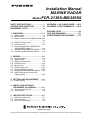
Installation Manual
MARINE RADAR
Model FCR-2139S-BB/2839S
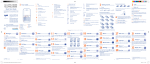
SAFTY INSTRUCTIONS ..........................i
SYSTEM CONFIGURATION ..................iii
EQUIPMENT LISTS................................iv
1. MOUNTING......................................1-1
1.1 Antenna Unit .......................................1-1
1.2 Monitor Unit.........................................1-8
1.3 Radar Control Unit/Trackball Control Unit
............................................................1-8
1.4 Radar Processor Unit........................1-11
1.5 Processor Unit ..................................1-12
1.6 Sensor Adapter MC-3000S/3010A/
3020D/3030D (option) ......................1-14
1.7 Intelligent Hub HUB-3000 (option) ....1-15
1.8 Switching HUB HUB-100 (option) .....1-16
APPENDIX 1 JIS CABLE GUIDE.....AP-1
APPENDIX 2 ROD TERMINALS ......AP-2
PACKING LISTS ................................. A-1
OUTLINE DRAWINGS ........................ D-1
INTERCONNECTION DIAGRAM........ D-1
2. WIRING............................................2-1
2.1
2.2
2.3
2.4
2.5
2.6
2.7
2.8
2.9
Interconnection ...................................2-1
Antenna Unit .......................................2-2
Radar Processor Unit..........................2-6
Processor Unit ..................................2-10
Monitor Unit.......................................2-21
Power Supply Unit ............................2-22
Sensor Adapters (option) ..................2-23
Intelligent HUB HUB-3000 (option) ...2-42
How to Extend the Control Unit
Cable (option)...................................2-43
3. SETTING AND ADJUSTMENT .......3-1
3.1 Radar Setting ......................................3-1
4. INSTALLING OPTIONAL
EQUIPMENT (for RADAR).............4-1
4.1 Gyro Converter GC-10........................4-1
4.2 Junction Box .......................................4-9
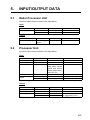
5. INPUT/OUTPUT DATA....................5-1
5.1 Radar Processor Unit..........................5-1
5.2 Processor Unit ....................................5-1
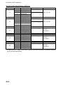
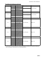
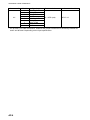
5.3 IEC 61162 Sentences .........................5-2
www.furuno.com
All brand and product names are trademarks, registered trademarks or service marks of their respective holders.
The paper used in this manual
is elemental chlorine free.
・FURUNO Authorized Distributor/Dealer
9-52 Ashihara-cho,
Nishinomiya, 662-8580, JAPAN
All rights reserved.
Printed in Japan
A : JUN . 2012
C : APR . 15, 2013
Pub. No. IME-36060-C
( REFU )
FCR-2139S-BB
0 0 0 1 7 6 1 3 7 1 2
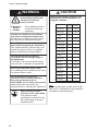
SAFTY INSTRUCTIONS
The operator and installer must read the applicable safety instructions before attempting to
install or operate the equipment.
DANGER
Indicates a potentially hazardous situation which, if not avoided,
will result in death or serious injury.
WARNING
Indicates a potentially hazardous situation which, if not avoided,
could result in death or serious injury.
CAUTION
Warning, Caution
Indicates a potentially hazardous situation which, if not avoided,
can result in minor or moderate injury.
Prohibitive Action
Mandatory Action
DANGER
Wear a safety belt and hard hat when working on the antenna unit.
Serious injury or death can result if someone falls from the radar antenna
mast.
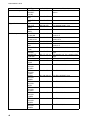
WARNING
Radio Frequency Radiation Hazard
The radar antenna emits electromagnetic radio frequency (RF) energy which can be
harmful, particularly to your eyes. Never look directly into the antenna aperture from a close
distance while the radar ius in operation or eexpose yourself to the transmitting antenna at a
close distance. Distances at which RF radiation level of 100, 50 and 10 W/m2 are given in the
table below.
Note: if the antenna unit is installed at a close distance in front of the wheel house, your
administration may require halt of transmission within a certain sector of antenna
revolution.
This is possible. Ask your FURUNO representive or dealer to provide this feature.
Transceiver Magnetron
Model
*2
FCR-2139S /
FCR-2839S
RTR-080
(S-30 kw)
MG5223F
Antenna *1
SN36AF
*1
SN36AF: 12 ft
*2
FCR-2139S: available in blackbox configuration.
100W/m 2
0.1 m
50W/m 2
0.7 m
10W/m2
2.0 m
i
SAFTY INSTRUCTIONS
WARNING
Do not open the equipment
unless totally familiar with
electrical circuits and
service manual.
ELECTRICAL
SHOCK
HAZARD
Only qualified personnel
should work inside the
equipment.
Construct a suitable service platform
from which to install the antenna unit.
Serious injury or death can result if someone falls from the radar antenna mast.
Turn off the power at the mains switchboard before beginning the installation.
Fire, electrical shock or serious injury can
result if the power is left on or is applied
while the equipment is being installed.
Be sure that the power supply is
compatible with the voltage rating of
the equipment.
Connection of an incorrect power supply
can cause fire or damage the equipment.
Use only the specified power cable.
Fire or damage to the equipment can result
if a different cable is used.
Do not install the monitor unit,
processor unit or control unit where
they may get wet from rain or
water splash, or in a dusty environment.
Water in the units can result in fire,
electrical shock, or damage the equipment.
Attach protective earth
securely to the ship's body.
The protective earth
(grounding) is required for the
AC power supply to prevent
electrical shock.
ii
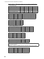
CAUTION
Observe the following compass safe
distances to prevent deviation of a
magnetic compass:
Standard Steering
compass compass
Antenna Unit
3.95 m
2.55 m
Processor
Unit(EC-3000)
2.40 m
1.55 m
1.65 m
1.05 m
0.85 m
0.55 m
Monitor Unit
(MU-190)
Monitor Unit
(MU-231)
Radar Processor
Unit (RPU-013)
ECDIS Control
Unit (RCU-024)
Radar Control
Unit (RCU-025)
1.35 m
0.85 m
0.30 m
0.30 m
0.30 m
0.30 m
Trackball Control
Unit (RCU-026)
0.30 m
0.30 m
Junction Box
(RJB-001)
1.10 m
0.70 m
0.85 m
0.55 m
1.00 m
0.60 m
Intelligent HUB
(HUB-3000)
1.20 m
0.75 m
Sensor Adapter
(MD-3000S)
2.05 m
1.35 m
Sensor Adapter
(MD-3010A)
0.75 m
0.50 m
Sensor Adapter
(MD-3020D)
1.05 m
0.70 m
Sensor Adapter
(MD-3030D)
0.90 m
0.60 m
Power Supply
Unit (PSU-007)
Switching Hub
(HUB-100)
Note
For more information, please refer to IMO
SN/Circ.271 “Guidelines for the installation
of shipborne radar equipment.”
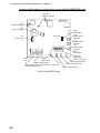
SYSTEM CONFIGURATION
220 VAC, 3ø, 60 Hz
200 VAC, 3ø, 50 Hz
440 VAC, 3ø, 60 Hz
380 VAC, 3ø, 50 Hz
For HSC spec
220 VAC, 3ø, 50 Hz
220 VAC, 3ø, 60 Hz
440 VAC, 3ø, 60 Hz
#
110 VAC, 3ø,
RU-5693
60 Hz
#
220 VAC, 3ø,
RU-6522
50 Hz
#
440 VAC, 3ø,
RU-5466-1
50 Hz
#: Not available for HSC spec.
Sub Display 1
Sub Display 2
110-115/220-230 VAC
1ø, 50/60 Hz
440VAC
1ø, 50/60 Hz
Transformer
RU-1803
Sensor Adapter**
or Switching HUB
HUB-100
Radar Control
Unit RCU-025
OR
Trackball Control Unit
RCU-026
ECDIS Control Unit
RCU-024
OR
Radar Control
Unit RCU-025
OR
Trackball Control Unit
RCU-026
POWER
SUPPLY Performance
Monitor
UNIT
PSU-007
Gyro Converter
GC-10
RPU-013
RADAR
PROCESSOR
UNIT
Radiator
SN36AF
ANTENNA UNIT
Chassis
RSB-098/099
RSB-100/101/102
(for HSC)
JB***
A-D Converter
Gyrocompass
Heading Sensor
LAN
Brake Unit
BR-001/002
Serial 1, 2
IEC-61162-2
(Gyrocompass1), AIS)
EC-3000
PROCESSOR
UNIT
Monitor Unit
MU-190*: FCR-21x9
MU-231*: FCR-28x9
Digital In (ACK IN)
VDR
Intelligent Hub
HUB-3000
Serial 3 - 8
IEC-61162-1
(EPFS2)(navigator),
SDME3)(Speed Log),
Echo sounder,
Wind, Alarm****,
Navtex, etc.)
Digital Out 1 - 6****
1: System Fail
2: Power Fail
3: Normal Close 1
4: Normal Close 2
5: Normal Open 1
6: Normal Open 2
100-115/220-230 VAC
Dashed lines indicate
Category of Units
1ø, 50/60 Hz
optional or local supply
Antenna Unit: Exposed to the weather
equipment.
All other units: Protected from the weather
1) Use the gyrocompass having an update rate that is adequate for the ship’s rate of turn.
Gyrocompass must have update rate better than 40 Hz (HSC) or 20 Hz (other than HSC).
2) Connect the EPFS which is approved in accordance with the requirements of the IMO in
resolution MSC.112(73) is used. The GPS speed may not meet IMO requirements unless
type approved for compliance with IMO resolution MSC.96(72).
3) Connect the SDME which is approved in accordance with the requirements of IMO in
resolution MSC.96(72) is used.
For FCR-2139S-BB, a monitor unit is prepared by user.
* These monitors have been approved by the IMO, MU-190 for CAT 2C and CAT 2HC, MU-231
for CAT 1C and CAT 1HC. If a different monitor is to be used on IMO vessels, its effective
diameter must meet the applicable Category requirements:
CAT 1C and CAT 1HC: effective diameter 320 mm or higher
CAT 2C and CAT 2HC: effective diameter 250 mm or higher
For installation, operation and viewing distance of other monitor, see its manuals.
** Control Serial MC-3000S, Analog IN MC-3010A, Digital IN MC-3020D, Digital OUT MC-3030D
*** Junction boxes are required for more than 100 m antenna cables.
**** Contact output for Alarm
(Load current) 250 mA
(Polarity) Normally Open: 2 ports, Normally Close: 2 ports
Serial I/O for alarm is also possible, which complies with IEC 61162-1.
iii
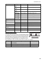
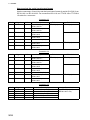
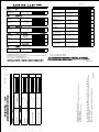
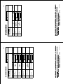
EQUIPMENT LISTS
Standard Supply
Name
Antenna Unit
Power Supply Unit
Monitor Unit
Processor Unit*
Processor Unit*
Control Unit
Installation Materials
Accessories
Spare Parts
Type
SN36AF
RSB-098
Code No.
-
RSB-099
-
RSB-100
RSB-101
RSB-102
PSU-007
MU-231
RPU-013
EC-3000
RCU-025
RCU-026
CP03-27201
CP03-35000
CP03-35010
CP03-35020
CP03-35030
CP03-35040
CP03-35050
CP03-35060
CP03-35070
CP03-27301
CP03-25602
CP24-02100
FP03-10101
FP24-00601
FP24-00701
FP24-00801
SP03-14404
SP03-14405
SP24-00601
SP24-00602
008-538-720
000-021-352
000-021-353
000-021-354
000-021-355
000-021-356
000-021-357
000-021-358
000-021-359
008-538-740
008-535-940
000-020-557
008-538-730
001-170-650
001-170-820
001-170-920
008-535-910
008-535-920
001-170-660
001-170-670
Qty
Remarks
1
Radiator
Antenna
1
200 VAC 3φ 50 Hz
Chassis
220 VAC 3φ 60Hz
380 VAC 3φ 50 Hz
440 VAC 3φ 50 Hz
200 VAC 3φ 50 Hz
Antenna
Chassis
220 VAC 3φ 60 Hz
for HSC
440 VAC 3φ 60 Hz
1
1
For FCR-2839S
1
For radar function
1
For chart function
1
Standard type
1
Trackball type
1
For antenna unit
1
15 m cable RW-9600, w/CP03-35001
30 m cable RW-9600, w/CP03-35001
40 m cable RW-9600, w/CP03-35001
50 m cable RW-9600, w/CP03-35001
15 m cable RW-9600, w/CP03-35002
30 m cable RW-9600, w/CP03-35002
40 m cable RW-9600, w/CP03-35002
50 m cable RW-9600, w/CP03-35002
1
For PSU-007
1
For RPU-016
1
For EC-3000
1
For antenna unit
1
For EC-3000
1
For RCU-025
1
For RCU-026
1
For RPU-013, 100 VAC
1
For RPU-013, 220 VAC
1
For EC-3000, 100 VAC
1
For EC-3000, 100 VAC
*: This radar has two processor units; RPU-013 and EC-3000. In this book, RPU-013 is called “radar processor unit” and EC-3000 is called “processor unit”.
iv
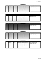
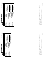
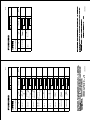
EQUIPMENT LISTS
Optional Supply
Name
Sensor Adapter
Switching HUB
Intelligent HUB
Bracket Assembly
Dust Cover
Monitor Replacement
Kit
Junction Box
Hood Assembly
Monitor Unit
Flush Mount Kit
Gyro Converter
Performance Monitor
Control Unir
Transformer Unit
Installation Materials
Spare Parts
Type
MC-3000S
MC-3010A
MC-3020D
MC-3030D
HUB-100
HUB-3000
OP26-5
OP26-15
OP26-21
26-007-1201
26-007-2141
OP26-22
OP26-23
OP26-26
OP26-27
RJB-001
OP26-6
OP26-16
OP26-24
OP26-25
MU-190
MU-231
OP26-12
OP26-17
OP26-13
OP26-14
OP26-18
OP26-19
GC-10-2
PM-51
RCU-025
RCU-026
RCU-024
Code No.
000-016-270
001-116-730
001-139-310
001-116-260-10
001-121-240-10
001-139-320
001-139-360
001-139-390
001-139-570
001-080-930
001-116-740
001-139-370
001-139-380
001-116-280
001-116-750
001-116-290
001-116-300
000-017-273
000-017-274
000-080-440
000-081-261
-
RU-1803
-
RU-3305
-
RU-5693
-
RU-6522
-
RU-5466-1
-
CP03-28900
CP03-28910
CP03-28920
SP24-00801
000-082-658
000-082-659
000-082-660
001-235-320
Remarks
Serial type
Analog IN
Digital IN
Digital OUT
See manual of HUB-100.
For MU-190
For MU-231
For MU-190
For MU-190
For MU-231
For MU-190, flushmount
For MU-190, desktop
For MU-190, hood
For MU-231, desktop
For more than 100 m antenna cable
For MU-190
For MU-231
For MU-190
For MU-231
For 21x9-BB
For MU-190
For MU-231
For two MU-190s
For three MU-190s
For two MU-231s
For three MU-231s
Mandatory for IMO radar
Radar standard type
Trackball type
ECDIS standard type
Converts 440 VAC to 100 VAC, for
processor unit
Converts 110/115/220/230 VAC to
100 VAC, for de-icer
Converts 110 VAC to 220 VAC, for
transceiver unit
Converts 220 VAC to 200 VAC, for
transceiver unit
Converts 440 VAC to 220 VAC, for
transceiver unit
FR-FTPC-CY 10 m, w/armor
FR-FTPC-CY 20 m, w/armor
FR-FTPC-CY 30 m, w/armor
For HUB-3000
v
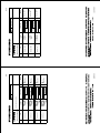
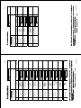
EQUIPMENT LISTS
Name
Connector Assy.
LAN Cable Assy.
Signal Cable
Cable Assy
vi
Type
DSUB9PDSUB9PL10.0M
MOD-Z072100+
MOD-Z072020+
S03-9-5 (8-8P)
S03-9-10
(8-8P)
S03-9-15
(8-8P)
DVI-D/D
S-LINK 5M
DVI-D/D
S-LINK 10 M
00619-001
DSUB9P-X2L5M
DSUB9P-X2L10M
DSUB9P-X2L5M-WP
DSUB9P-X2L10M-WP
OP24-32
DVI-BNCX5L2000
6TPSHXH12X2L5.0SP1
6TPSHXH12X2L10SP1
6TPSHXH12X2L20SP1
6TPSHXH12X230SP1
6TPSHXH12X2L5.0SP2
6TPSHXH12X2L10SP2
6TPSHXH12X2L20SP2
6TPSHXH12X2L30SP2
Code No.
000-150-676-11
Remarks
For control the MU-190/231 brilliance
000-167-177-10
10 m
000-167-175-10
2m
008-206-640
008-206-650
For external radar, 5 m
For external radar, 10 m
008-209-160
For external radar, 15 m
001-132-960-10
Between processor and control
units, 5 m
001-133-980-100 Between processor and control
units, 10 m
000-171-765-10
For MU-190/231
001-188-260
Between processor and control
units, 5 m
001-188-270
For MU-190/231 brill control, 5 m
000-177-053-10
001-188-300
001-204-150
For monitor unit, 5 m, waterproofing
type
For monitor unit, 5 m, waterproofing
type
USB cable, 5 m (w/EMI core)
For VDR connection
001-186-260-10
For RCU-024/025, 5 m
001-186-270-10
For RCU-024/025, 10 m
001-186-280-10
For RCU-024/025, 20 m
001-186-290-10
For RCU-024/025, 30 m
001-186-310-10
For RCU-026, 5 m
001-186-320-10
For RCU-026, 10 m
001-186-330-10
For RCU-026, 20 m
001-186-340-10
For RCU-026, 30 m
000-177-247-10
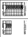
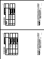
EQUIPMENT LISTS
Name
Cable
10 Core Multiple Cable
AC/DC Power Supply
Unit
Case Gasket
IPX2 Kit
Flush Mount
Control Unit Replacement Kit
Terminal Opener
Operator’s Manual
Crimping Tool
Type
MC1.5-WL600
MC1.5-WL1000
MC1.5-WL2000
MC1.5-WL3000
DTI-C5E350
VCV L=10M
DTI-C5E350
VCV L=20M
DTI-C5E350
VCV L=30M
RW-4864
PR-240
Code No.
001-187-480-10
Remarks
For sensor adapters, 6 m
001-187-480-10
For sensor adapters, 10 m
001-187-490-10
For sensor adapters, 20 m
001-187-500-10
For sensor adpters, 30 m
001-197-600-10
LAN cable, CAT5E, 10 m
001-197-610-10
LAN cable, CAT5E, 20 m
001-197-620-10
LAN cable, CAT5E, 30 m
001-103-640-10
000-013-632
10 m
OP24-28
OP24-29
OP24-23
OP24-27
OP24-31
001-169-970
001-169-960
001-171-780
001-171-820
001-181-700
For MC-3000S
For MC-3010A/3020D/3030D
For EC-3000
For RCU-026
For RCU-024/025
OP24-33
OME-36040-*
CRIMPFOX10
S
001-188-850
000-176-132-**
001-206-920
For ferrule
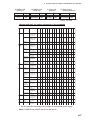
About the category sticker
Comply with MSC.192(79)
CAT 1HC
CAT 1C
CAT 2HC
CAT 2C
This radar meets the requirements in IEC62388 (Marine navigation and radio communication equipment and systems-Ship born
radar-Performance requirements, method of testing and required
Sticker for category
test results.) Check the appropriate box on the sticker which is
pre-attached on the radar processor unit, according to your radar’s specification. Refer to the table shown below to confirm your category.
Category
CAT 1C
CAT 1HC
CAT 2C
CAT 2HC
Radar type
FCR-2819, FCR-2829, FCR-2839S, FCR-2829W,
FCR-2839SW
FCR-2819, FCR-2829, FCR-2839S
FCR-2119-BB, FCR-2129-BB, FCR-2139S/BB
FCR-2119-BB, FCR-2129-BB, FCR-2139S/BB
ANT, rotation speed
Normal speed
HSC
Normal speed
HSC
vii
EQUIPMENT LISTS
This page is intentionally left blank.
viii
1.
MOUNTING
NOTICE
Do not apply paint, anti-corrosive
sealant or contact spray to coating or
plastic parts of the equipment.
Those items contain organic solvents that
can damage coating and plastic parts,
especially plastic connectors.
1.1
Antenna Unit
Mounting consideration
• The antenna unit is generally installed either on top of the wheelhouse, on the radar
mast, or on a suitable platform. Locate the antenna unit in an elevated position to
permit maximum target visibility.
• A line of sight from the antenna unit to the bow of the ship should hit the surface of
the sea in not more than 500 m or twice the ship’s length, depending which value is
smaller, for all load and trim conditions.
less than 500 m or twice the ship's length
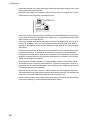
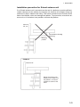
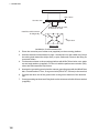
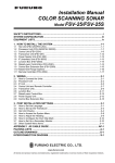
• Mount the antenna unit so that any blind sectors caused by objects (mast, etc.) are
kept to minimum. No blind sector should exist in arc of the horizon from ahead to
22.5° aft of the beam to either side (see Figure 1 below). Also, individual blind sectors of more than 5°, or the total arc of both blind sectors of more than 20°, should
not occur in the remaining arc (Figure 2). Note that any two blind sectors separated
by 3° or less are regarded as one sector.
270°
90°
22.5°
22.5°
Figure 1
a, b, c: less than 5° respectively
a+b+c+... : less than 20°
less than 3°
Figure 2
1-1
1. MOUNTING
• Install the antenna unit safety away from interfering high-power energy source and
other transmitting radio antenna.
• Keep the lower edge of the antenna unit above the safety rail by 500 mm or more.
• Two antenna units should be mounted as below:
more than 20°
more
than 1 m
• No funnel, mast or derrick should be within the vertical beamwidth of the antenna
unit in the bow direction, especially zero degrees ±5°, to prevent blind sectors and
false echoes on the radar picture.
• It is rarely possible to place the antenna unit where completely clear view in all directions is available. Thus, you should determine the angular width and relative
bearing of any shadow sector for their influence on the radar at the first opportunity
after fitting.
• Locate a direction finder antenna clear of the antenna unit to prevent interference
to the direction finder. A separation of more than two meters is recommended.
• A magnetic compass will be affected if the antenna unit is placed too close to the
magnetic compass.Observe the compass safe distances on page ii to prevent deviation of the magnetic compass.
• Do not paint the radiator aperture, to ensure proper emission of the radar waves.
• The antenna base is made of cast aluminium. To prevent electrolytic corrosion of
the antenna base, use the seal washers and corrosion-proof rubber mat ground the
unit with the ground wire (supplied).
• Deposits and fumes from a funnel or other exhaust vent can adversely affect the
aerial performance and hot gases may distort the radiator position.The antenna unit
must not be mounted where the temperature is more than 70°C.
• Leave sufficient space around the unit for maintenance and servicing. See antenna
unit outline drawing for recommended maintenance space.
1-2
1. MOUNTING
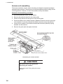
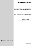
Installation precaution for S-band antenna unit
If an S-band antenna unit is mounted near the end of a platform to provide sufficient
rotation clearance for the radiator, the antenna unit, because of its weight, swings up
and down by ship’s vibration and rolling. This exerts excessive levels of stress at the
base of the radiator, which can damage the radiator. To prevent this, relocate the antenna unit, or if relocation is not possible, reinforce the platform.
Mast for
DF, etc.
Remarkable vibration
(pitching)
Mounting
position
EXAMPLE
Mast for DF
Mount the antenna unit
directly on the mast or on
the platform, as near as
possible to center of the
mast.
1-3
1. MOUNTING
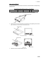
Antenna unit assembling
The antenna radiation and the antenna housing are shipped in separate packages.
Assemble them as below. The antenna unit may be assembled before hosting it to the
mounting platform. However, do not lift the antenna unit by the radiator.
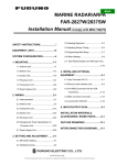
Antenna unit assembling procedure
1. Screw the guide pins (2 pcs.) in the radiator.
2. Remove the protective cap from the choke guide.
3. Grease O-ring and set it to the groove of the choke guide.
4. Place the radiator on the radiator bracket. (Radiator direction is shown by the logo
on the bracket. If reversely oriented the radiator cannot be set to the bracket.)
5. Loosely fix the radiator to the radiator bracket with hex bolts (M10x25), spring
washers and flat washers.
6. Remove the guide pins and tighten hex bolts.
Antenna radiator
Radiator
front
Guide pin (2 pcs.)
Arrow mark for the radiator front.
Assembling the radiator bracket
CAUTION
Be sure to remove the guide pins
after fixing the radiator.
Injury may result if the guide pins loosen
and fall.
1-4
1. MOUNTING
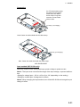
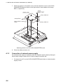
How to lift the antenna unit
1. Fix the antenna radiator to the antenna unit chassis as shown on page 1-3.
2. Attach the lifting fixtures and collars as shown below.
3. Position the radiator as shown below and arrange the rope A and B.
Lifting fixture
Collar for fixing
Supplied as accessories.
Remove after installation.
Spring washer
Plat washer (M12)
Lifting hook (2 pcs.)
Hex bolt (M12X20)
(Torque 63.5Nm)
Remove lifting fixture, coat threads
of hex bolts with silicone grease, and
then insert bolts in antenna chassis.
B
1.8m
*
A
2m
*
* Protect radiator with
cardboard or cloth at
locations marked with
asterisk.
Attachment of lifting fixtures, collar and ropes
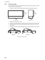
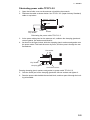
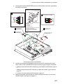
Fastening the antenna unit to the mounting platform
See the figure on the next page for antenna unit mounting.
1. Referring to the antenna outline drawing, drill eight fixing holes of 15 mm in diameter in the radar mast platform or the deck.
• The diameter of the mast for fixing the antenna unit platform must be over 250
mm.
• The thickness of the antenna unit platform must be over 15 mm.
• The reinforcement rib must be installed diagonally as shown below.
1-5
1. MOUNTING
Over 15mm
Use two nuts.
250mm diameter or more,
6 mm thick or more
Install the reinforcement
rib diagonally.
Ship's bow
Bottom view
installation of reinforcement ribs
2. Place the corrosion-proof rubber mat (supplied) on the mounting platform.
3. Hoist the antenna unit as shown on page 1-4 and place it on the rubber mat. Orient
the cable gland toward the ship’s stern (or port, starboard). Remove the lifting fixtures and collars.
4. Fix the antenna base to the mounting platform with M12x70 hex bolts, nuts, washers and seal washers (supplied). For the unit with the performance monitor (PM),
orient the PM toward the ship’s stern.
5. Arrange the grounding terminal at the nearest grounding spot with the M6x25 hex
bolt, nut and washers. Then, fix a ground wire (RW-4747, 340 mm) to the terminal.
6. Connect the other end of the ground wire to the ground terminal of the antenna
unit.
7. Coast grounding terminal and fixing bolts on the antenna unit with silicone sealant
(supplied).
1-6
1. MOUNTING
Seal
washer
Corrosion
proof
rubber
mat
Use two nuts.
(Torque 63.5Nm)
Ground terminal
G1_1/4-A
Set corrosion-proof rubber mat,
bolt antenna unit to mounting
location, and coat exposed
hardware with silicone sealant.
Hex bolt
Flat washer
Flat washer
Spring washer
Hex nut
Ground wire
Coat with
silicone
sealant.
Coat with silicone sealant after
fastening ground wire.
OR
Ground wire
Hex nut
Spring washer
Flat washer
Hex bolt
Ground wire
Welding
Antenna chassis
Arrange ground terminal as close
as possible to antenna unit.
Ground terminal provided on antenna base.
Mounting of antenna unit
1-7
1. MOUNTING
1.2
Monitor Unit
To mount the monitor unit, see the operator’s manual for MU-231 (OMC-44690).
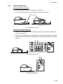
1.3
Radar Control Unit/Trackball Control Unit
The control units can be mounted on a desktop, with or without the KB fixing metal
(supplied), which mounts the control units at an angle. The control unit also can be
mounted in a console panel using the optional kit.
Note: The control unit RCU-025 can be used instead of the RCU-020 (for FAR-2xx7)
mounted in the connection stand (OP03-184 or OP26-20) using the option OP24-31.
Mounting consideration
When you select a mounting location, keep in mind the following points:
• Select a location where the control unit can be operated conventionally.
• Locate the unit away from heat sources because of heat that can build up inside the
cabinet.
• Locate the equipment away from places subject to water splash and rain.
• Leave sufficient space at the sides and rear of the unit to facilitate maintenance.
• Determine the mounting location considering the length of the signal cable between
the control unit and the processor unit.
• A magnetic compass will be affected if the control unit is placed too close to the
magnetic compass. Observe the compass safe distances on page i to prevent compass malfunction.
• Make sure that the ground wire
is connected between the earth
terminal on the chassis and the
ship’s earth.
• Fasten the USB cable with the
cable tie.
USB cable
1-8
Cable routing peg
Cable tie
Ex. ECDIS control unit, bottom view RCU-02
1. MOUNTING
1.3.1
Desktop Mounting
Fixing with KB fixing metal
1. Fix the KB fixing metal to the bottom of the control unit.
2. Fix it to a desired location with self-tapping screws (local supply).
KB fixing metal
RCU-026
RCU-025
Side view of control units
Fixing without KB fixing metal
1. Drill four mounting holes of 5 mm diameter referring to the outline drawing at the
back of this manual.
2. Fix the control unit with four screws (M4) from under side of the desktop. (The M4
screws with a sufficient length for the thickness of the desktop should be provided
locally.)
Control Unit RCU-025
Control unit RCU-026
1-9
1. MOUNTING
1.3.2
Flush mounting
Use the optional flush mount kit (RCU-025: OP24-24, RCU-026: OP24-27) to mount
the control unit in a console panel.
1. Prepare a cutout in the mounting location as shown in the figure as below.
170+2
170+2
388+2
110+2
For RCU-025
For RCU-026
2. Set the control unit to the cutout.
3. Attach the mounting plate to the control unit with four screws from the rear side.
4. Screw the wing screw to each mounting plate and then insert hex. bolt to each
wing screw.
5. Fasten each wing screw and then fasten the hex. nuts as shown in figure below.
RCU-026
RCU-025
Side view of control units
1-10
1. MOUNTING
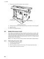
1.4
Radar Processor Unit
Mounting considerations
When selecting a mounting location, keep in mind the following points:
• Locate the processor unit away from heat sources because of heat that can build
up inside the cabinet.
• Locate the equipment away from places subject to water splash and rain.
• Leave sufficient space at the sides and rear of the unit to facilitate maintenance.
• A magnetic compass will be affected if the processor unit is placed too close to the
magnetic compass. Observe the compass safe distances on page ii to prevent deviation of a magnetic compass.
Mounting procedure
1. Fix the unit with four M6 bolts, or self-tapping screws.
2- 7 FIXING HOLES
R3
2-FIXING NOTCH
.5
7
Floor mounting or bulkhead mounting
Note: If you fix the unit, cable entry upside, never remove the screw M3x10 that joints
the upper case assy. and lower case assy. of the processor unit.
Upper case assy.
Lower case assy.
Unfasten this screw.
M3x10
Processor unit
1-11
1. MOUNTING
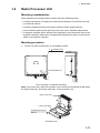
1.5
Processor Unit
1.5.1
Mounting considerations
When you select a mounting location, keep in mind the following points:
• Locate the processor unit away from heat sources because of heat that can build
up inside the cabinet.
• The vibration at the mounting location should be minimum.
• Locate the equipment away from places subject to water splash and rain.
• Make the service clearance of 100 mm in front of the vent hole (left side).
• Leave sufficient space at the sides and rear of the unit to facilitate maintenance.
• Make sure that the ground wire is connected between the earth terminal on the
chassis and the ship’s earth.
• A magnetic compass will be affected if the processor unit is placed too close to the
magnetic compass. Observe the compass safe distances on page ii to prevent compass malfunction.
• Do not remove the dummy plate to prevent the wrong operation of the power switch.
The items behind the plate are for use by the serviceman.
Keep the dummy
plate in this
position.
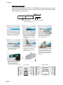
Processor unit, front view
• Mount the processor unit on the floor, or on a bulkhead with the following direction
(horizontal), because of the DVD drive unit.
UP
OK
1-12
1. MOUNTING
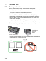
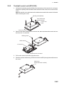
1.5.2
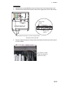
How to mount the processor unit
Use six bolts (M6, local supply) to mount the processor unit.
1. Use 10 binding head screws (M4x8, supplied) to attach the chassis bases 1 and
2 to the processor unit.
Note: For bulkhead mounting, attach the chassis base 2 so that the notches on it
are facing the deck.
Chassis base 1
Notches
Notches
Chassis base 2
2. Use six bolts (M6, local supply) to fix the processor unit.
: Bolt holes (notches)
1-13
1. MOUNTING
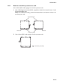
1.6
Sensor Adapter MC-3000S/3010A/3020D/3030D
(option)
Mounting considerations
When you select a mounting location, keep in mind the following points:
• Locate the adapter away from heat sources because of heat that can build up inside
the cabinet.
• The vibration should be minimal.
• Locate the equipment away from places subject to water splash and rain.
• Make sure that the ground wire is connected between the earth terminal on chassis
and the ship’s earth.
• Leave sufficient space at the sides and rear of the unit to facilitate maintenance.
• A magnetic compass will be affected if the adapter is placed too close to the magnetic compass. Observe the compass safe distances at the front of this manual to
prevent interference to a magnetic compass.
• Select the mounting location considering the numbers of the sensor adapters connected.
Maximum eight MC-3000S can be connected to a sensor network.
Maximum 10 sensor adapters (MC-3010A/3020D/3030D) can be connected to a
MC-3000S. However, note that five MC-3010A can be connected.
• Select the mounting location so that the length of cables among the sensor adapters
(MC-3000S, 3010A, 3020D and 3030D) is less than 6 m. If the length is more than
6 m, the equipment may not work properly.
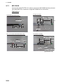
How to mount the sensor adapter
1. Unfasten a pan head screws to remove the cover from the sensor adapter.
2. Fasten four self-tapping screws (4x20, supplied) to fix the sensor adapter.
3. Reattach the cover.
MC-3000S
1-14
MC-3010A/3020D/3030D
1. MOUNTING
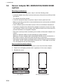
1.7
Intelligent Hub HUB-3000 (option)
Use the optional Intelligent Hub HUB-3000 to connect gateway network equipment.
This network cannot be connected with the LAN network on board. Note that a commercial PC cannot be connected in this network, other than for the maintenance.
Mounting considerations
When you select a mounting location, keep in mind the following points:
• Locate the adapter away from heat sources because of heat that can build up inside
the cabinet.
• The vibration should be minimal.
• Locate the equipment away from places subject to water splash and rain.
• Make sure that the ground wire is connected between the earth terminal on chassis
and the ship’s earth.
• Leave sufficient space at the sides and rear of the unit to facilitate maintenance.
• A magnetic compass will be affected if the adapter is placed too close to the magnetic compass. Observe the compass safe distances at the front of this manual to
prevent interference to a magnetic compass.
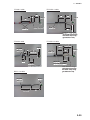
How to mount the intelligent hub HUB-3000
1. Use two binding screws (M3x6, supplied) to attach the cable clamp (supplied) to
the bottom of the HUB-3000.
Binding screw
(M3x6, 2 pcs)
Cable clamp
HUB-3000, bottom view
2. Fasten four self-tapping screws (4x20, supplied) to fix the unit.
: Screw holes
1-15
1. MOUNTING
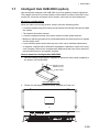
1.8
Switching HUB HUB-100 (option)
Use the optional Switching HUB HUB-100 to connect sensor networks. This network
cannot be connected with the LAN network on board. Note that a commercial PC cannot be connected in this network, other than for the maintenance. The total length of
all cables connected to the hub is 6 m.
For the mounting procedures, see the operator’s manual for HUB-100 (Pub. No.OMC35191).
Mounting considerations
When you select a mounting location, keep in mind the following points:
• Locate the adapter away from heat sources because of heat that can build up inside
the cabinet.
• The vibration should be minimal.
• Locate the equipment away from places subject to water splash and rain.
• Make sure that the ground wire is connected between the earth terminal on chassis
and the ship’s earth.
• Leave sufficient space at the sides and rear of the unit to facilitate maintenance.
• A magnetic compass will be affected if the adapter is placed too close to the magnetic compass. Observe the compass safe distances at the front of this manual to
prevent compass malfunctions.
1-16
2.
WIRING
2.1
Interconnection
Wiring consideration
To lessen the chance of picking un electrical interference, avoid where possible routing the signal cable near other onboard electrical equipment (radars, transmitting radio antennas, etc.). Also avoid running the cable in parallel with power cables. When
crossing with other cable, the angle should be 90° to minimize the magnetic field coupling.
The signal cable between the antenna and processor units is available in lengths of
15 m, 30 m, 40 m, and 50 m. Whatever length is used, it must be unbroken; namely,
no splicing allowed. Use the signal cable as short as possible to minimize attenuation
of the signal.
The radar should be connected to an emergency power source, as required by SOLAS II-1.
Notice for the network construction
• Use the optional Switching Hub HUB-100 to connect the sensor networks. For the
gateway networks, use the optional Intelligent Hub HUB-3000.
• Do not connect the LAN network on board to the above optional HUBs. Also, commercial PCs cannot be connected to the gateway network, other than for maintenance.
• When connecting the FEA-2xx7 or FAR-2xx7 series via LAN network, use the INS
network.
Notice on wiring
• Use the optional USB cable (type: OP24-32) to connect to USB port on the control
unit.
• The length of the USB cable should be within 5 m to prevent equipment trouble.
• The length of LAN cables should be within 50 m.
• Use the CAT5E or CAT6 LAN cables for the network if available locally.
• If LAN cables are not available locally, use the optional LAN cables (FR-FTPC-CY
for sensor network, DTI-C5E350 VCV for gateway network).
• If extension or division of the DVI or ERGB cables is necessary, use the dividers
shown below.
• DVI cable divider: DVI-12A (maker: INAGICS)
• RGB divider: CIF-12H, DD-106 or WBD-14F (maker: INAGENICS)
• Make sure that the ground wires are connected between the ground terminals on
each equipment and the ship’s earth.
• If a UPS (user supply) is connected to this equipment, be sure that the grounding
lamp does not light.
2-1
2. WIRING
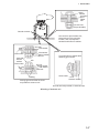
Antenna unit
Monitor Unit
MU-231
(FCR-28x9)
TB801
TB802
Junction Box
RJB-001*
100-230 VAC
DVI-D/D SINGLE LINK cable
5 m/10 m
DSUB9P-X2 cable
5 m/10 m
RW-9600
15/30/40/50 m
(Max.100 m)
FR-FTPC-CY cable Sensor Adapter
or HUB-100
Radar
Processor unit
RPU-013
TTYC-10 cable
MOD-Z702 cable
Processor Unit
EC-3000
XH10P-XH2P cable
(2 m)
System fail, Power fail,
Normal close 1/2.
Normal open 1/2,
ACK IN
TTYCS-4
TTYCS-1Q
Junction Box
RJB-001*
MPYC-7
HUB-3000
or TTYC-1T
GYRO
(SYNCHRO, 100-230 VAC
STEPPER, or
IEC61162-2)
USB
memory
100-115 VAC/220-230 VAC
x2
GPS, LOG, E/S,
WIND, ALRM,
NAVTEX etc.
x6
100-230 VAC
x2
30 m
5m
(for USB)
DPYC-2.5
GYRO, AIS
Trackball Control Unit
RCU-026
Radar Control Unit
RCU-025
USB
memory
*: If the cable run between the antenna unit and radar processor unit is more than 100m,
use Junction box RJB-001. However, the maximum length is 300m.
: Cable requires fabrication
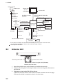
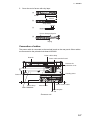
2.2
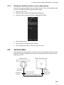
Antenna Unit
G1-A
G3/4-C
Gland for power cable
Antenna motor switch
G1_1/4-A
G1_1/4-A
Gland for signal cable (RW-9600)
Antenna unit, bow view
1. Open the right side cover on the antenna unit with the hex wrench.
2. Unfasten the cable gland for the signal cable and remove the gasket, flat washers
and blind lid.
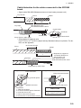
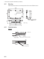
3. Fabricate the signal cable RW-9600 as follows.
a) Remove the outer sheath, armor and inner sheath as shown on the next page.
b) Unravel the shield to expose the wires in the inner layer.
2-2
2. WIRING
c) Adjust the length of each core considering its location on the terminal board
TB801.
d) Trim each wire (except coaxial wire) considering its location on the terminal
board.
e) Trim the shield leaving 200 mm and attach crimp-on lug FV5.5-4.
f) Remove insulation of each wire by about 6mm.
g) Fabricate the coaxial cable as shown right.
Outer sheath
Armor
Inner sheath
20 mm
Shield
460 mm
5 mm
Coaxial cable
360
Vinyl cable
Shield
Wire
6
14 5 9
200
mm
Conductor
Fold back shield.
FV5.5-4
Shield wire
Coaxial cable
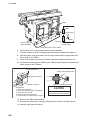
4. As shown in the figure below, side the clamping gland, flat washer, gasket and flat
washer on the signal cable.
5. Fold back armor and pass the flat washer as shown in the figure below. Cut and
trim the armor around the flat washer.
Flat washer
Vinyl sheath
Clamping gland
Gasket
Cut and trim armor.
Passing clamping gland, washer and gasket on the signal cable
2-3
2. WIRING
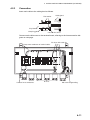
TB801
TB801
Coaxial cable
TB802
TB board
Pass the signal
cable RW-9600.
Clamp shield of
coaxial cable.
Grounding point for the shield.
6. Confirm that armor is grounded between two flat washers.
7. Coat the screw part of the clamping gland with silicone sealant and tighten it.
8. Use the opener, and insert each core (except coaxial cable) to appropriate connector plug on the TB801.
9. Loosen two screws and slide the TB board assembly upward and pull it out.
10. Connect the coaxial cable to TB802 on the TB board and clamp the shield with the
cable clamp on the TB board.
Wiring for WAGO connector
Press downward.
Wiring for Coaxial cable
Clamp shied with bracket.
Terminal opener
Wire
WAGO connector
Twist
Procedures
1. Twist the conductor.
2. Press the terminal opener downward.
3. Insert the wire to hole.
4. Remove the terminal opener.
5. Pull the wire to confirm that it is ecure.
Tighten conductor with screw.
CAUTION
Do not use crimp-on lug to prevent
contact resistance from increasing.
11. Remount the TB board assembly.
12. Connect the shield wire to the grounding point as shown in the figure above.
13. Seal the cable gland with putty.
2-4
2. WIRING
Fabricating power cable TPYCY-2.5
1. Open the left side cover on the antenna unit with the hex wrench.
2. Fabricate the cable as shown below. Use TPYCY-2.5 (Japan Industry Standard)
cable or equivalent.
Approx. 170 mm
25 mm
5 mm
FV2-4
Anti-corrosive
Vinyl sheath
Armor
Sheath
Fabricating the power cable TPYCY-2.5
3. At the power cable gland on the antenna unit, unfasten the clamping gland and
remove gasket, flat washers and blind lid.
4. As shown in the figure below, slide the clamping gland, washers and gasket onto
the power cable. Fold back the armor by 5mm, and then pass it through the two
flat washers.
Flat washer
Vinyl sheath
Clamping gland
Gasket
Cut and trim armor.
Passing clamping gland, washers and gasket on power cable TPYCY-2.5
5. Coat the screw part of the clamping gland with silicone sealant and tighten it.
6. Pass the power cable behind the terminal block, and then pass it through the locking wire saddle.
2-5
2. WIRING
7. Fix the crimp-on-lug FV2-4 (blue) to each conductor.
Terminal board
for power cable
Pass the power
supply cable here.
Antenna unit, left view
8. Connect crimp-lug to the terminal block referring to the interconnection diagram.
9. Attach the cover.
10. Seal the cable gland with putty.
2.3
Radar Processor Unit
Four cables are terminated at the radar processor unit: the antenna unit cable, LAN
cable, power switch cable, and the power cable. Cables other than the power cable
come with a connector pre-attached to them for connection to the processor unit. Fabricate the power cable as below. For the power cable, use DPYC-2.5 (Japan Industry
Standard) cable or the equivalent.
Note: For AC: Pass the AC line through a double-contact breaker (shipyard supply)
2.3.1
Fabricating the power cable
1. Cut armor of the cable by 40 mm.
2. Cut vinyl sheath by 35 mm.
3. Remove insulation of wires by about 10 mm. Fix crimp-on lugs to the cores.
4. Scrape off paint of the armor by 40 mm.
2-6
2. WIRING
5. Cover the end of armor with vinyl tape.
(a)
DPYC-2.5
Approx. 40 mm
Armor
35 mm
(b)
Vinyl sheath
10 mm
(c)
40 mm: Scrape off paint.
(d)
Taping
Connection of cables
The power cable is connected to the terminal board on the rear panel. Other cables
are connected to the printed circuit board 03P9342.
Power cable clamp
Network
Power cable terminal board
Remove the
protection cover.
F70
FUSE
1
15
DC/AC
F1
2
Heading senor
Power cable
9 14
ACK
Cable clamp
GND TERMINAL
17
21
2
3
4
5
HDG
f9
6
18
19
20
RSD
f18.9
1
7
AIS
AD100
8
28
GYRO
PSU004
24
24'
f7
VDR IN
VDR OUT
f7.4
26
Power control cable
Antenna unit
Gyrocompass
AD-100
Processor unit
2-7
2. WIRING
Location of connectors
Cable clamp
03P9342
J621
J612
J608
Gyro converter board
or AD-100
J607
J620
J606
J611
J619
J605
J603
Gyro converter board
To Sub display *
(SEMI-LOG)
To Sub display *
(FULL-LOG)
Do not use this
connector to input
the radar video.
J618
J610
J604
J602
PSU
J617
Cable from antenna unit
J614 J615
J601
J609
J654
Tx HV line
03P9342
2-8
Power control cable
to EC-3000
J616
J613
Heading sensor
Coaxial cable
2. WIRING
Cable fabrication for the cables connected to the 03P9342
board
• Signal cable RW-9600 (Between antenna unit and radar processor unit)
Vinyl sheath
Armor
Shield
450
60
5
After exposing cores,
wind shield around the armor.
Vinyl tape
Coaxial cable
6
14 5 9
Coaxial cable
Clamp here by cable clamp.
Conductor
Fold back shield.
• Other cables for optional units
Use TTYCS-1 or TTYCS-1Q (Japan Industry Standard cable) or equivalent. For details, see the appendix.
Armor
60: Scrape off paint.
Shield
L= Depends on equipment
connected. Measure at
the processor unit.
After exposing cores,
wind shield around the armor.
L
Vinyl tape
5
6
Clamp here by cable clamp.
Wiring for WAGO connector
Press downward.
Wiring for Coaxial cable
Clamp shied with bracket.
Terminal opener
Wire
WAGO connector
Twist
Procedures
1. Twist the conductor.
2. Press the terminal opener downward.
3. Insert the wire to hole.
4. Remove the terminal opener.
5. Pull the wire to confirm that it is ecure.
Tighten conductor with screw.
CAUTION
Do not use crimp-on lug to prevent
contact resistance from increasing.
2-9
2. WIRING
Connection of Sub-display
A conventional remote display and/or FCR-2107 series radar can be connected to
J617 and J 618 in processor unit as sub-display. However, the GAIN and STC controls
function differently depending on J617 and J618. Refer to the tablet to connect subdisplays.
Port
J617
Overall gain
(FULL-LOG)
Conventional remote display
FCR-2107 series radar
Even if input video level is adThe gain is 8 dB lower than that on
justed to 4 Vp-p, the gain is 8 dB the master radar.
lower than that on the master radar.
GAIN control The GAIN control functions.
The GAIN control does not function.
STC control The STC control functions.
The STC control does not function.
J618
Overall gain When input video level is adjust- The gain is almost same as that on
(SEMI-LOG)
ed to 4 Vp-p, the gain becomes the master radar.
the same as that on the master
radar.
GAIN control The GAIN control functions.
The GAIN control does not functon.
STC control The STC control functions, how- The STC control does not function.
ever this control is added on the
signal adjusted by the master radar. So this port is not recommended to use.
2.4
Processor Unit
2.4.1
How to connect cables to terminals on the processor unit
Use screws (M3x6, supplied) to attach the wiring plate 1 and wiring plate 2 assy to the
processor unit. Connect the cables shown below to the connectors at the front of the
processor unit. After the connection, bind cables to the appropriate fixing metal with
the cable ties (supplied).
For the cables from the monitor unit (type: DVI-D/D SLINK5M/10M (MU-190 only),
DSUB9P-X2-L5/10M) and ground wire, connect them to the processor unit directly
(without fixing to a wiring plate). Tighten the fixing screws on these connectors to prevent disconnection from the processor unit.
Note: Connect the cables so that they do not interfere with the opening or closing of
the DVD tray.
2-10
2. WIRING
Slide the plate toward
the unit to hide LED
and switches.
Wiring plate 2 assy
Wiring plate 1
COM2
DVI3
Cable clamp
(See the next page.)
MU-190/231
(DVI3: DVI-D/D S-LINK cable
or DVI-BNCX5-L2000 cable,
COM2: DSUB9P-X2-L cable)
DVI2 MU-190/231
LAN1
HUB-3000
(DTI-C5E350 VCV
cable)
Power cable
(IEC60320-C13L5M cable)
(DVI2: DVI-D/D
S-LINK cable
or DVI-BNCX5L2000 cable)
LAN2
Ground wire
(IV-2sq.,
local supply)
USB1
HUB-100/MC-3000S
(FR-FTPC-CY cable,
within 50m)
LAN3
RCU-024/026
(TS-20-071-1 cable)
Not used.
USB4
For USB printer
USB2/3
Optional control unit
RCU-024/026
(TS-20-071-1 cable)
COM1
DVI1
MU-190/231
(DVI1: DVI-D/D S-LINK cable,
COM1: DSUB9P-X2-L cable)
Cables connected at the wiring plate 1
• Power cable (Type: IEC60320-C13-L5M)
• LAN cable to the LAN3 port
Cables connected at wiring plate 2 assy
• USB cables from the control units
• Printer cable
• LAN cable (type: DTI-C5E350 VCV) from the HUB-3000
• LAN cable (type: FR-FTPC-CY) from the HUB-100/MC-3000S
2-11
2. WIRING
Fabricating LAN cable
Fabricate the LAN cable (FR-FTPC-CY, DTI-C5E350 VCV), as shown below. (Wrap
both edges of the armor with vinyl tape.) Confirm that the shield of the cable touches
to the shell of the modular plug.
Armor
Outer vinyl sheath
30
55
Inner vinyl sheath
Wrap vinyl tape
1
3
2
25mm
approx. 9mm
Remove the outer sheath by
approx 25 mm. Be careful
not to damage inner shield
and cores.
Expose inner vinyl sheath.
4
6
5
approx. 11mm
approx. 9mm
Drain wire
Fold back drain wire and
cut it, leaving 9 mm.
Straighten and flatten the
core in order and cut them,
leaving 11 mm.
7
Using special crimping tool
MPT5-8 (PANDUIT CORP.),
crimp the modular plug.
Finally check the plug visually.
Insert the cable into the modular
plug so that the folded part of
the shield enters into the plug
housing. The drain wire should
be located on the tab side of
the jack.
[Cross cable]
1 WHT/GRN
2 GRN
3 WHT/ORG
4 BLU
5 WHT/BLE
6 ORG
7 WHT/BRN
8 BRN
2-12
Fold back the shield, wrap it
onto the outer sheath and
cut it, leaving 9 mm.
WHT/ORG 1
ORG 2
WHT/GRN 3
BLU 4
WHT/BLE 5
GRN 6
WHT/BRN 7
BRN 8
[Straight cable]
1 WHT/ORG
2 ORG
3 WHT/GRN
4 BLU
5 WHT/BLE
6 GRN
7 WHT/BRN
8 BRN
WHT/ORG 1
ORG 2
WHT/GRN 3
BLU 4
WHT/BLE 5
GRN 6
WHT/BRN 7
BRN 8
2. WIRING
IPX2 kit
The optional IPX2 kit (Type: OP24-23, Code No.: 001-171-780) protects the connectors shown below to waterproofing standard IPX2.
Contents of IPX2 kit
Name
Binding Screw
Connector Gasket 1
Connector Gasket 2
Rainproof Cover
Gasket Clamping Plate
Type
#4-40UNCX3/16
24-014-0107
24-014-0108
24-014-0109
24-014-0114
24-014-0115
Code No.
000-176-619-10
100-367-730-10
100-367-741-10
100-372-202-10
100-372-210-10
100-372-220-10
Qty
10
2
3
1
2
3
Remarks
For D-sub connectors
For DVI connectors
For D-sub connectors
For DVI connectors
1. Set the connector gasket to the unused connector not used.
2. Fasten two binding screws to fix the connector gasket.
Gasket clamping plate
Connector gasket
3. Peel the paper from the double-sided tape on the rainproof cover, then attach the
cover to the position shown below by using four screws preattached to the processor unit.
Processor unit
Screws to fix the rainproof cover
Rainproof cover
2-13
2. WIRING
2.4.2
How to connect cables inside the processor unit
Fabrication
Fabricate JIS cables as shown below to connect them to the WAGO connectors on
the I/O Board 24P0124 inside the processor unit.
For locations of cables and cores, see the sticker on the reverse side of the top cover.
(All dimensions in millimeters)
Fabrication of TTYCS series
Armor
Shield
L
30
5
Vinyl tape
After exposing cores,
wind shield around the armor.
6
Clamp here by cable clamp.
Cable tie
(supplied)
Cable type (JIS)
TTYCS-4, TTYCSLA-4,
TTYCS-1Q, TTYCSLA-1Q
Length of “L”
TTYCS-10, TTYCSLA-10
380
400
Fabrication of TTYCSLA series
Sheath
30
100
Drain wire
L
5
Vinyl tape
Pass the vinyl sheath (local supply)
onto the drain wire, then attach the
crimp-on lug (preattached to the
earth clamp on the processor unit) to it.
6
Cable tie
(supplied)
Clamp here by cable clamp.
Crimp-on lugs
for drain wires
Wiring for WAGO connector
Press downward.
Terminal opener
Wire
Twist
WAGO connector
Procedures
1. Twist the conductor.
2. Press the terminal opener downward.
3. Insert the wire to hole.
4. Remove the terminal opener.
5. Pull the wire to confirm that it is ecure.
2-14
Processor unit, cover removed
2. WIRING
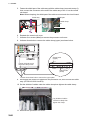
Connection
1. Unfasten four screws (M4x8) to remove the top cover from the processor unit.
2. Unfasten three bolts shown below to remove the upper plate of the cable clamp.
J5 J8 J3 J12
J11 J6 J9 J4
J14
J7 J10 J13
Clamp holes
(upper)
Loosen this bolt to use
the lower clamp holes.
Clamp holes
(lower)
Loosen these three bolts to remove the upper plate.
Processor unit, top view
3. Pass the cables through the clamp holes, then fasten the bolts removed at step 2
to fix the cables.
Lay shields of cables
under this clamp then
tighten the clamp.
2-15
2. WIRING
4. Connect the WAGO connectors appropriately to the I/O Board, referring to the interconnection diagram.
J12 (main control unit)
For J13 and J14 (sub
control units), see the figure
at step 2 on the previous page.
5. Bind the cables to the fixing metal in the processor unit with the cable ties (supplied).
Fixing metal
Screws for drain wires
of TTYCSLA cables
(Pass the drain wires through
the shrink tubes (local supply),
then attach these crimp-on lugs
to the drain wire.)
6. For TTYCSLA series cables, pass the drain wire into the shrink tube (local supply), then fasten crimp-on lugs at the end of drain wires to screws shown above.
Example of wiring (inside the processor unit)
2-16
2. WIRING
2.4.3
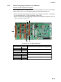
How to set jumper blocks on I/O Board
How to set the termination resistors
Use the jumper blocks JP1 and JP2 on the I/O Board (24P0124) to set the termination
resistor J3 and J4 on or off. The default setting is termination resistor: on.
• When setting the starting/ending terminal for the multipoint connection, or multipoint
is not connected (CH1 or CH2): termination resistor ON
• When not setting the starting/ending terminal for the multipoint connection (CH1 or
CH2): termination resistor OFF
JP1
J3
JP2
J4
J11
Processor unit, I/O Board (24P0124)
1-2
2-3
1-2
2-3
Jumper block J1
SHORT
OPEN
OPEN
SHORT
1-2
2-3
1-2
2-3
Jumper block J2
SHORT
OPEN
OPEN
SHORT
Connector J3
Termination resistor: ON (default setting)
Termination connector: OFF
Connector J4
Termination resistor: ON (default setting)
Termination connector: OFF
2-17
2. WIRING
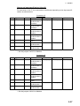
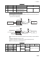
How to select the serial input/output format
Use the connectors J3 and J4 to set the input/output format for serial CH1/CH2, from
IEC-61162-1 or IEC-61162-2. For connectors J5 to J10, use TTYCS-1Q or TTYCSLA1Q cable for a connector.
Connector J3
Pin #
Signal
1
TD1-A
In/Out
Out
2
TD1-B
Out
3
RD1-A
In
4
RD1-B
In
5
6
ISOGND1
RD1-H
In
7
RD1-C
In
-
Description
Serial CH1, output
IEC61162-1/2
Serial CH1, output
IEC61162-1/2
Serial CH1, input
IEC61162-2
Serial CH1, input
IEC61162-2
Isolation GND (CH1)
Serial CH1, input
IEC61162-1
Serial CH1, input
IEC61162-1
IEC61162-2
TTYCS(LA)-4
IEC61162-1
TTYCS(LA)-4
No connection
No connection
TTYCS(LA)-4
IEC61162-2
TTYCS(LA)-4
IEC61162-1
TTYCS(LA)-4
Connector J4
Pin #
Signal
1
TD2-A
In/Out
Out
2
TD2-B
Out
3
RD2-A
In
4
RD2-B
In
5
6
ISOGND2
RD2-H
In
7
RD2-C
In
-
Description
Serial CH2, output
IEC61162-1/2
Serial CH2, output
IEC61162-1/2
Serial CH2, input
IEC61162-2
Serial CH2, input
IEC61162-2
Isolation GND (CH2)
Serial CH2, input
IEC61162-1
Serial CH2, input
IEC61162-1
No connection
No connection
TTYCS(LA)-4
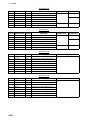
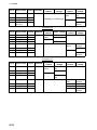
Connector J5
Pin#
1
2
3
4
5
2-18
Signal
TD3-A
TD3-B
RD3-H
RD3-C
GND
In/Out
Out
Out
In
In
-
Description
Serial CH3, output IEC61162-1
Serial CH3, output IEC61162-1
Serial CH3, input IEC61162-1
Serial CH3, input IEC61162-1
GND
Remarks
Use TTYCS(LA)-1Q,
IREC61162-1 only
2. WIRING
Connector J6
Pin#
1
2
3
4
5
Signal
TD4-A
TD4-B
RD4-H
RD4-C
GND
In/Out
Out
Out
In
In
-
Description
Serial CH4, output IEC61162-1
Serial CH4, output IEC61162-1
Serial CH4, input IEC61162-1
Serial CH4, input IEC61162-1
GND
Remarks
Use TTYCS(LA)-1Q,
IREC61162-1 only
Connector J7
Pin#
1
2
3
4
5
Signal
TD5-A
TD5-B
RD5-H
RD5-C
GND
In/Out
Out
Out
In
In
-
Description
Serial CH5, output IEC61162-1
Serial CH5, output IEC61162-1
Serial CH5, input IEC61162-1
Serial CH5, input IEC61162-1
GND
Remarks
Use TTYCS(LA)-1Q,
IREC61162-1 only
Connector J8
Pin#
1
2
3
4
5
Signal
TD6-A
TD6-B
RD6-H
RD6-C
GND
In/Out
Out
Out
In
In
-
Description
Serial CH6, output IEC61162-1
Serial CH6, output IEC61162-1
Serial CH6, input IEC61162-1
Serial CH6, input IEC61162-1
GND
Remarks
Use TTYCS(LA)-1Q,
IREC61162-1 only
Connector J9
Pin#
1
2
3
4
5
Signal
TD7-A
TD7-B
RD7-H
RD7-C
GND
In/Out
Out
Out
In
In
-
Description
Serial CH7, output IEC61162-1
Serial CH7, output IEC61162-1
Serial CH7, input IEC61162-1
Serial CH7, input IEC61162-1
GND
Remarks
Use TTYCS(LA)-1Q,
IREC61162-1 only
Connector J10
Pin#
1
2
3
4
5
Signal
TD8-A
TD8-B
RD8-H
RD8-C
GND
In/Out
Out
Out
In
In
-
Description
Serial CH8, output IEC61162-1
Serial CH8, output IEC61162-1
Serial CH8, input IEC61162-1
Serial CH8, input IEC61162-1
GND
Remarks
Use TTYCS(LA)-1Q,
IREC61162-1 only
2-19
2. WIRING
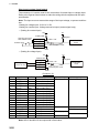
How to set contact input/output
The connector J11 can be used for the connection of contact input or voltage input.
Refer to the figures shown below to make the wiring which complies with the input
specification.
Note: The input must not exceed the range of the input voltage, to prevent malfunction.
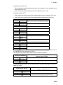
-Setting for voltage input: 21.6V to 31.2V
-Setting for contact input: Voltage cannot be input (contact signal only).
• (Setting for contact input)
5V
12V
470Ω/ 0.5W
Use NH connector
and AWG24 wire.
Contact input
Register
DC12V_OUT
DIGI_INx
DIGI_RTNx
GND(DC12V)
2.2kΩ / 1W
to MC-DIN
circuit
GND
Photocoupler circuit
GND
• (Setting for voltage input)
5V
12V
470Ω/ 0.5W
DC voltage input
(21.6V to 31.2V)
DC12V_OUT
DIGI_INx
DIGI_RTNx
GND(DC12V)
+
-
Register
2.2kΩ / 1W
GND
Photocoupler circuit
to MC-DIN
circuit
GND
Connector J11
Pin #
1
2
3
4
5
6
7
8
9
10
11
12
13
14
15
16
17
Signal name
SYS_FAIL-A
SYS_FAIL-B
PWR_FAIL-A
PWR_FAIL-B
NC1-A
NC1-B
NC2-A
NC2-B
NO1-A
NO1-B
NO2-A
NO2-B
DC12V_OUT
DIGI_IN1
DIGI_RTN1
GND (DC12V)
GND
In/Out
Out
Out
Out
Out
Out
Out
Out
Out
Out
Out
Out
Out
Out
In
Out
In
-
Description
System fail output
System fail output
Power fail output
Power fail output
Alarm output (NC1)
Alarm output (NC1)
Alarm output (NC2)
Alarm output (NC2)
Alarm output (NO1)
Alarm output (NO1)
Alarm output (NO2)
Alarm output (NO2)
ACK input
ACK input
ACK input
ACK input
GND
Contact input
TTYCS(LA)-10
Voltage input
TTYCS(LA)-10
#13-#14: short
No connection
TTYCS(LA)-10
TTYCS(LA)-10
No connection
NO connection
Note: NC1/2 and NO1/2 are output with a fixed value.
2-20
2. WIRING
2.5
Monitor Unit
For the wiring of the monitor unit MU-190/231, see the operator’s manual supplied with
the monitor unit.
Mounting consideration
(Standard type)
• Connect the ECDIS main monitor to the DVI1 and COM1 ports.
• For the sub ECDIS monitor, connect it to the DVI2 and COM2 port.
(Conning type)
• ECDIS main monitor: DVI1 and COM1 ports, conning monitor: DVI3 port and COM2
ports
• When an ECDIS sub monitor is added to the above connection, connect it to the
DVI2 port (the brilliance adjustment is not available).
(VDR connection, ask your dealer)
To connect a VDR, it is necessary to output data in analog format. See the installation
manuals for VDR to prepare the cables to use.
• When connecting a VDR to the DVI3 port::
Use the optional DVI-BNCX5-L2000 cable to output RGB signal from the DVI-I. Adjustment of the output picture is necessary.
• When connecting a VDR to the DVI2 port:
Use a DVI/RGB converter (maker: IMAZINICS, type: DVI-12A, local supply) to convert DVI output from DVI2 port to RGB.
The [INSTALLATION SETTING] menu appears only when the power is turned on for
the first time after installation of the monitor unit.
Menu
INSTALLATION SETTING
EXT BRILL CTRL
RS-485
SERIAL BAUDRATE 4800bps
COLOR CALIBRATION
ON
KEY LOCK
ON
(OFF/DVI1/DVI2/RS-232C/RS-485/USB)
(4800/9600/19200/38400)
(OFF/ON)
(OFF/ON)
SAVE AND EXIT
(NO/YES)
YES
Menu item
Adjust the settings referring to the following table.
EXT BRILL
CTRL
RS-485
SERIAL
BAIDRATE
4800bps
COLOR
CALIBRATION
ON
KEY LOCK
ON
DVI PWR
SYNC*
YES
*: [DVI PWR SYNC] is the slide switch at the bottom rear of the monitor unit. Confirm
that this switch is set to [ON] (default setting). See Slide switch below for details.
2-21
2. WIRING
Slide switch
Set the slide switch to “ON” (default setting). This setting automatically powers the
monitor unit on or off according to the DVI signal input. The power switch of the monitor unit is inoperative.
Note: The OFF position provides control of the monitor unit power with the power
switch of the monitor unit.
How to open the [INSTALLATION SETTING] menu
Turn off the monitor unit. While you hold the DISP key, press the BRILL key to turn on
the monitor unit. Press and hold the DISP key for more than five seconds.
Note: When the [DVI PWR SYNC] slide switch is ON, turn on the connected external
equipment while you press the DISP key to turn on the monitor unit.
2.6
Power Supply Unit
Wire the unit as shown in the interconnection diagram.
Thermal relay
Relay
K2: Connect
input line.
(W)(v)
XK1: Connect output line.
TB1: Connect control line.
Cable clamp: Clamp the armors of the cable.
2-22
2. WIRING
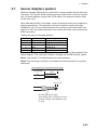
2.7
Sensor Adapters (option)
Maximum eight MC-3000S can be connected to a sensor network (for the redundant
connection: 16). The MC-3000S (serial input/output, IEC61162-2/1, 4ch) can connect
max. 10 sensor adapters using the MC1.5-W cables. The maximum number of MC3010A units is five.
When fabricating the MC1.5-W cables, use the lot terminal (ferrule type, supplied) to
maintain performance. This fabrication requires the optional crimping tool (type:
CRIMPFOX 10S). For the relations between the connectors and rod terminals, see
page AP-2. Also, the stickers attached on the reverse side of the covers show the detailed connections.
Attache the cables to the applicable pins.
Pin No.
1
2
3
4
5
Cable color
Red
Black
White
Blue
Gray
Signal
24V_OUT or 24V_IN
24V_GND
MODBUS-A
MODBUS-B
GND
Use the ferrule-type terminals (supplied) to connect the cables to the terminals in the
sensor adapters. This connection requires a crimping tool (CRIMPFOX10S, option).
Note 1: Use the MC1.5-W cable between the sensor adapters.
Note 2: The total length of the MC1.5-W cables should be less than 6 m to prevent
malfunction.
How to attach the rod terminal (ferrule type)
Vinyl sheath
6mm
Core
0.5 to 1 mm
Rod terminal (ferrule type):
After attaching the rod terminal, use the
optional crimping tool CRIMPFOX 10S
to crimp.
2-23
2. WIRING
2.7.1
MC-3000S
Use the LAN cable FR-FTPC-CY cable to connect the MC-3000S and the processor
unit. With HUB-100, a maximum of eight MC-3000S can be connected.
Fabrications
TTYCS-1Q cable
LAN cable (FR-FTPC-CY)
(J8)
#1 to 4: 110
#5 to 8: 95
See section 2.1.2. for
the fabrication.
50
30
80 or
more
30
Vinyl tape
(width: 10)
MC1.5-W-L600/1000/2000/3000 cable
(J9)
#1 to 4: 100
#5 to 8: 90
Core: 6
Shield (fold back)
TTYCSLA-1Q cable
(J8)
#1 to 4: 110
#5 to 8: 95
Shield
(fold back)
Vinyl tape
10
20
2-24
100
Core: 6
80 or
more
Vinyl tape
(width: 10)
(J9)
#1 to 4: 100
#5 to 8: 90
Core: 6
60 mm:
Pass drain wire through
vinyl sheath (local supply),
then attach crimp-on lug
(pre-attached in unit).
2. WIRING
TTYCSLA-1 cable
TTYCS-1 cable
100
30
100
80
Core: 6
Core: 6
80
Shield (fold back)
Vinyl tape
(width: 10)
Vinyl tape
(width: 10)
60
Pass drain wire through
vinyl sheath (local supply),
then attach crimp-on lug
(pre-attached in unit).
TTYCS-4 cable
TTYCSLA-4 cable
80 or
more
Core: 6
Vinyl tape
(width: 10)
20
Vinyl tape
(width: 10)
J4/J6: 100
J5/J7: 120
80 or
more
No use: 50
(Wind tape to insulate.)
J4/J6: 100
J5/J7: 120
60
Core: 6
No use: 50
(Wind tape to insulate.)
Pass drain wire through
shrink tube (local supply),
then attach crimp-on lug
(pre-attached in unit).
DPYC-1.5 cable
Vinyl tape
(width: 10)
Core: 6
80
(or more)
85
2-25
2. WIRING
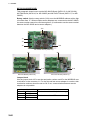
Connections
Unfasten four screws to remove the cover, pass the cables through the clamps and
attach the cables to respective connectors. The shield part of the cable (or drain wire)
must be fastened by (connected to) the clamp.
For TTYCSLA cables, pass the drain
wire into the shrinking tube (local supply),
then use these crimp-on lugs and screws
to connect drain wires from TTYCSLA cables
to here.
J7
J5
J2 J1
J4
J8
J6
DPYC1.5
J9
TTYCS-4/
TTYCSLA-4
FR-FTPC-CY cable
IV-1.25sq. (Local supply)
TTYCS-1Q/
TTYCSLA-1Q
MC1.5-W-L cable
Note: Fasten the cable shield with the cable clamp.
How to set NC/NO output (J2)
The POWER FAIL signal on the connector J2 can be set to NC (normal close) output
or NO (normal open) output as shown in the table below.
Connector J2
Pin #
1
2
3
4
5
2-26
Signal name
24V_IN
24V_GND
PWR_FAIL_A
PWR_FAIL_COM
PWR_FAIL_B
In/Out
Out
Out
Out
Remarks
24 VDC
GND (24 VDC)
Power fail output
Power fail output
Power fail output
NO
DPYC-1.5
TTYCS(LA)-1
No connection
NC
No connection
TTYCS(LA)-1
2. WIRING
How to set input specification (J4 to J9)
For connectors J4 to J7, the connections are different depending on the input specifications as shown below.
Connector J4
Pin # Signal name
1
TD1-A
In/Out
Out
2
TD1-B
Out
3
RD1-A
In
4
RD1-B
In
5
ISOGND1
6
RD1-H
In
7
RD1-C
In
-
Remarks
Serial CH1, output IEC61162-1/
2/modbus
Serial CH1, output IEC61162-1/
2/modbus
Serial CH1, output IEC61162-2/
modbus
Serial CH1, output IEC61162-2/
modbus
Isolation, GND
(CH1)
Serial CH1, output IEC61162-1
Serial CH1, output IEC61162-1
IEC61162-2
TTYCS(LA)-4
IEC61162-1
TTYCS(LA)-4
Modbus*
TTYCS(LA)-4
No connection No connection
No connection TTYCS(LA)-4
*: Set the jumpers J20/J21 to Modbus.
Connector J5
Pin # Signal name
1
TD2-A
In/Out
Out
2
TD2-B
Out
3
RD2-A
In
4
RD2-B
In
5
ISOGND2
6
RD2-H
In
7
RD2-C
In
-
Remarks
Serial CH2, output IEC61162-1/
2/modbus
Serial CH2, output IEC61162-1/
2/modbus
Serial CH2, output IEC61162-2/
modbus
Serial CH2, output IEC61162-2/
modbus
Isolation, GND
(CH2)
Serial CH2, output IEC61162-1
Serial CH2, output IEC61162-1
IEC61162-2
TTYCS(LA)-4
IEC61162-1
TTYCS(LA)-4
Modbus*
TTYCS(LA)-4
No connection No connection
No connection TTYCS(LA)-4
*: Set the jumpers J20/J21 to Modbus.
2-27
2. WIRING
Connector J6
Pin #
1
2
3
4
5
6
7
Signal name
TD3-A
TD3-B
RD3-A
RD3-B
ISOGND3
RD3-H
RD3-C
In/Out
Out
Out
In
In
In
In
Remarks
IEC61162-2
IEC61162-1
Serial CH3, output IEC61162-1/2 TTYCS(LA)-4 TTYCS(LA)-4
Serial CH3, output IEC61162-1/2
Serial CH3, output IEC61162-2
No connection
Serial CH3, output IEC61162-2
Isolation, GND (CH3)
Serial CH3, output IEC61162-1
No connection TTYCS(LA)-4
Serial CH3, output IEC61162-1
Connector J7
Pin #
1
2
3
4
5
6
7
Signal name
TD4-A
TD4-B
RD4-A
RD4-B
ISOGND4
RD4-H
RD4-C
In/Out
Out
Out
In
In
In
In
Remarks
IEC61162-2
IEC61162-1
Serial CH4, output IEC61162-1/2 TTYCS(LA)-4 TTYCS(LA)-4
Serial CH4, output IEC61162-1/2
Serial CH4, output IEC61162-2
No connection
Serial CH4, output IEC61162-2
Isolation, GND (CH4)
Serial CH4, output IEC61162-1
No connection TTYCS(LA)-4
Serial CH4, output IEC61162-1
Connector J8
Pin#
1
2
3
4
5
6
7
8
Signal name
TD5-A
TD5-B
RD5-H
RD5-C
TD6-A
TD6-B
RD6-H
RD6-C
In/Out
Out
Out
In
In
Out
Out
In
In
Description
Serial CH5, output IEC61162-1
Serial CH5, output IEC61162-1
Serial CH5, input IEC61162-1
Serial CH5, input IEC61162-1
Serial CH6, output IEC61162-1
Serial CH6, output IEC61162-1
Serial CH6, input IEC61162-1
Serial CH6, input IEC61162-1
Used cable
TTYCS-1Q or TTYCSLA-1Q
Connector J9
Pin#
1
2
3
4
5
6
7
8
2-28
Signal name
TD7-A
TD7-B
RD7-H
RD7-C
TD8-A
TD8-B
RD8-H
RD8-C
In/Out
Out
Out
In
In
Out
Out
In
In
Description
Serial CH7, output IEC61162-1
Serial CH7, output IEC61162-1
Serial CH7, input IEC61162-1
Serial CH7, input IEC61162-1
Serial CH8, output IEC61162-1
Serial CH8, output IEC61162-1
Serial CH8, input IEC61162-1
Serial CH8, input IEC61162-1
Used cable
TTYCS-1Q or TTYCSLA-1Q
2. WIRING
Case packing OP24-28
The optional kit OP24-28 protects the connectors on the MC-3000C to waterproofing
standard IPX2.
Case packing (type: OP24-28, code no.: 001-169-970)
Name
Case packing (serial)
Type
21-014-2051
Code No.
Qty
Remarks
100-367-880-10 2
For MC-3000S
1. Unfasten four binding screws to remove the cover from the adapter.
Binding screw
Cover
2. Peel the paper from the case packing, then attach the case packing to the reverse
side of the cover and the body unit as shown below.
Case packing
Cover (reverse side)
Case packing
Case packing
Body unit
Case packing
3. Attach the cover to the MC-3000S body unit.
2-29
2. WIRING
2.7.2
MC-3010A/3020D/3030D
• MC-3010A: Inputs analog signal. To use MC-3010A as current input, connect short
pins to each terminals.
• MC-3020D: Inputs digital signal (8ch contact input). Contact or voltage input is selectable (contact input requires jumper pins).
• MC-3030D: Outputs digital signal (8ch, normal open/close).
Fabrications
MC1.5-W-L600/1000/2000/3000 cable
TTYCSLA-1 (MC-3010A)
(Input)
80
120
30
60
Core: 6
Vinyl tape
(width: 10)
Vinyl tape Shield
(width: 10) (fold back)
Core: 6
60
Pass drain wire into
vinyl sheath (local supply),
then attach crimp-on lug
(pre-attached in unit).
MC1.5-W-L600/1000/2000/3000 cable
(Output)
30
100
80 or
more
Vinyl tape Shield
(width: 10) (fold back)
Core: 6
MPYC-12 cable (MC-3030D)
80 or
more
TTYCS-1 (MC-3010A)
125
Vinyl tape
(width: 10)
Shield
(fold back)
MPYC-12 cable (MC-3020D)
80 or
more
2-30
135
95
85
Not used: Cut with 50,
and wind tape to insulate.
Core: 6
60
30
Core: 6
Not used: Cut with 50,
and wind tape to insulate.
Core: 6
2. WIRING
Connection
For TTYCSLA cables, pass
the drain wire through the
shrink tube, then attach
these crimp-on lugs and
screws to connect drain
wires to here.
J5
J4
J3
J2
IV-1.25sq. (Local supply)
TTYCS-1/
TTYCSLA-1
J1
MC1.5-W-L cable
Note: Fasten the cable shield with the cable clamp.
J4
J6
J3 J5
J2
J1
MPYC-12
IV-1.25sq. (Local supply)
MC1.5-W-L cable
Note: Fasten the cable shield with the cable clamp.
MC-3020D/3030D
Input method (MC-3010A only)
Select the method of the analog data input, power voltage or power current.
Note 1: The input must not exceed the range of the input voltage, to prevent malfunction.
-Setting for voltage input: -10V to +10V or 0 to 10V (depending on the setting)
-Setting for contact input: Voltage 4mA to 20mA.
Note 2: When changing the input method, turn off the MC-3010A and on again to put
change in effect.
2-31
2. WIRING
• Power voltage: Input the amount of power voltage change to the operational amplifier.
AN +15V
+15V
+VS1
AN-IN
AN-GND
CURR-JP1
Voltage
source
Vin
+VS2
Opeamp
OutGnd
- VS2
InGnd
CURR-JP2
Jumper: open
- VS1
GND
1kΩ 1%0.5Wx2
Load
- 15V
AN GND AN - 15V
• Power current: Pass the power current to the shunt resistor, 1kΩ/parallel (combined
resistance: 500Ω) to input the amount of voltage change at the both ends of the resistor to the operational amplifier.
AN +15V
+15V
+VS1
AN- IN
AN- GND
CURR- JP1
CURR- JP2
Current
source
Jumper short
Vin
+VS2
Opeamp
OutGnd
- VS2
InGnd
- VS1
GND
1kΩ 1%0.5Wx2
Load
Use NH connector
and AWG24 cable.
- 15V
AN GND AN - 15V
Connector J3
Pin # Signal name
1
AN1_IN
2
AN1_GND
3
CURR1_JP1
In/Out
In
-
4
-
CURR1_JP2
Description
Power voltage
Analog 1 input
TTYCS(LA)-1
Analog 1 GND
Analog 1 input, power current/ Pin #3-#4: open
voltage setting jumper 1
Analog 2 input, power current/
voltage setting jumper 1
Power current
Pin #3-#4: short
Connector J4
Pin # Signal name
1
AN2_IN
2
AN2_GND
3
CURR2_JP1
In/Out
In
-
4
-
2-32
CURR2_JP2
Description
Power voltage
Analog 2 input
TTYCS(LA)-1
Analog 2 GND
Analog 2 input, power current/ Pin #3-#4: open
voltage setting jumper 1
Analog 2 input, power current/
voltage setting jumper 1
Power current
Pin #3-#4: short
2. WIRING
Connector J5
Pin # Signal name
1
AN3_IN
2
AN3_GND
3
CURR3_JP1
In/Out
In
-
4
-
CURR3_JP2
Description
Power voltage
Analog 3 input
TTYCS(LA)-1
Analog 3 GND
Analog 3 input, power current/ Pin #3-#4: open
voltage setting jumper 1
Analog 3 input, power current/
voltage setting jumper 1
Power current
Pin #3-#4: short
How to set ACK input (MC-3020D)
Use the connectors J3 to J6 on the MC-DIN Board (24P0116) to set the ACK input for
ACK1 to ACK8 as shown below.
• Input circuit for voltage input
5V
12V
470Ω/ 0.5W
DC voltage input
(21.6V to 31.2V)
+
-
Register
DC12V_OUT
DIGI_IN1
DIGI_RTN1
GND(DC12V)
2.2kΩ / 1W
to Processor unit
circuit
GND
Photocoupler circuit
GND
• Input circuit for contact input
5V
12V
Use NH connector
and AWG24 wire.
Contact input
470Ω/ 0.5W
Register
DC12V_OUT
DIGI_IN1
DIGI_RTN1
GND(DC12V)
2.2kΩ / 1W
GND
Photocoupler circuit
to Processor unit
circuit
GND
Note 1: The input must not exceed the range of the input voltage, to prevent malfunction.
-Setting for voltage input: 21.6V to 31.2V
-Setting for contact input: Voltage cannot be input (contact signal only).
Note 2: For analog input, see paragraph 2.7.2
Connector J3
Pin #
Signal name
In/Out
Remarks
1
DC12V_OUT
Out
ACK1 In
2
3
4
DIGI_IN1
DIGI_RTN1
GND
(DC12V)
In
Out
In
ACK1
contact
Pin #1-#2:
short
ACK
voltage
No connection
MPYC-12
MPYC-12
ACK2
contact
ACK2
voltage
Depending on ACK1 input
No connection
2-33
2. WIRING
Pin #
Signal name
In/Out
Remarks
5
DC12V_OUT
Out
ACK2 In
6
7
8
DIGI_IN2
DIGI_RTN2
GND
(DC12V)
In
Out
In
ACK1
contact
ACK
voltage
Depending on ACK2 input
ACK2
contact
Pin #1-#2:
short
ACK2
voltage
No connection
MPYC-12
MPYC-12
NO connection
Connector J4
Pin #
Signal name
In/Out
Remarks
1
2
3
4
5
DC12V_OUT
DIGI_IN3
DIGI_RTN3
GND (DC12V)
DC12V_OUT
Out
In
Out
In
Out
ACK3 In
6
7
8
DIGI_IN4
In
DIGI_RTN4
Out
GND (DC12V) In
ACK1
contact
Pin #1-#2:
short
ACK1 voltage
ACK2
contact
No connection
MPYC-12
ACK2
voltage
-
MPYC-12
No connection
ACK4 In
Pin #1-#2:
short
-
No connection
MPYC-12
MPYC-12
No connection
Connector J5
Pin #
Signal name
In/Out
Remarks
1
DC12V_OUT
Out
ACK5 In
2
3
4
DIGI_IN5
In
DIGI_RTN5
Out
GND (DC12V) In
5
DC12V_OUT
6
7
8
DIGI_IN6
In
DIGI_RTN6
Out
GND (DC12V) In
2-34
Out
ACK1
contact
Pin #1-#2:
short
ACK
voltage
No connection
MPYC-12
ACK2
contact
ACK2
voltage
-
MPYC-12
No connection
ACK6 In
Pin #1-#2:
short
-
No connection
MPYC-12
MPYC-12
NO connection
2. WIRING
Connector J6
Pin #
Signal name
In/Out
Remarks
1
DC12V_OUT
Out
ACK1 In
2
3
4
DIGI_IN1
In
DIGI_RTN1
Out
GND (DC12V) In
5
DC12V_OUT
6
7
8
DIGI_IN2
In
DIGI_RTN2
Out
GND (DC12V) In
Out
ACK1
contact
Pin #1-#2:
short
ACK
voltage
No connection
MPYC-12
ACK2
contact
ACK2
voltage
-
MPYC-12
No connection
ACK2 In
Pin #1-#2:
short
-
No connection
MPYC-12
MPYC-12
NO connection
How to set alarm output (MC-3030D)
Use the connector J3 to J6 on the MC_OUT Board (24P0117) to select NC (normal
close) or NO (normal open) for alarm output 1 to 8.
Connector J3
Pin
#
1
2
3
4
5
6
Signal
name
A1
COM1
B1
A2
COM2
B2
In/
Out
Out
Remarks
Alarm1
Out
Alarm1 NO
Out
MPYC-12
Alarm1 NC
Out
No connection
MPYC-12
Alarm2 NO
Out
Alarm2 NC
Out
-
No connection
Alarm2
Out
MPYC-12
No connection
MPYC-12
No connection
Connector J4S
Pin
#
1
2
3
4
5
6
Signal
name
A3
COM3
B3
A4
COM4
B4
In/
Out
Out
Remarks
Alarm3
Out
Alarm3 NO
Out
MPYC-12
Alarm3 NC
Out
No connection
MPYC-12
Alarm4 NO
Out
Alarm4 NC
Out
-
No connection
Alarm4
Out
MPYC-12
-
No connection
MPYC-12
No connection
2-35
2. WIRING
Connector J4
Pin
#
1
2
3
4
5
6
Signal
In/
name Out
A5
Out
COM5
B5
A6
COM6
B6
Remarks
Alarm5
Out
Alarm1 NO
Out
MPYC-12
Alarm1 NC
Out
No connection
MPYC-12
Alarm2 NO
Out
Alarm2 NC
Out
-
No connection
Alarm5
Out
MPYC-12
No connection
MPYC-12
No connection
Connector J6
Pin
#
1
2
3
4
5
6
2-36
Signal
In/
name Out
A7
Out
COM7
B7
A8
COM8
B8
Remarks
Alarm7
Out
Alarm7 NO
Out
MPYC-12
Alarm7 NC
Out
No connection
MPYC-12
Alarm8 NO
Out
Alarm8 NC
Out
-
No connection
Alarm8
Out
MPYC-12
No connection
No connection
MPYC-12
2. WIRING
Case packing OP24-29
The optional kit OP24-29 protects the connectors on the MC-3010A/3020D/3030D to
waterproofing standard IPX2.
Case packing (type: OP24-29, code no.: 001-169-970)
Name
Case packing (analog)
Type
21-014-2052-2
Code No.
100-367-961-10
Qty
Remarks
2
MC-3010A/3020D/3030D
1. Unfasten four binding screws to remove the cover from the adapter.
Cover
Binding screw
2. Peel the paper from the case packing, then attach the case packing to the reverse
side of the cover and the body unit as shown below.
Case packing
Case packing
Cover (reverse side)
Case packing
Case packing
Chassis
3. Attach the cover to the MC-3010A/3020D/3030D chassis.
2-37
2. WIRING
2.7.3
How to set jumper blocks in the sensor adapters
MC-3000S
See the jumper blocks in the MC-CS Board (24P0114) referring to the tables that follow.
J14 J22 J23 J15 J16 J17
S2
J19
J20 J21
MC-CS Board (24P0114)
Rotary switch: Use the rotary switch (S2) to set the Modbus address when setting
connectors J4/J5 to Modbus. The Modbus address set at J4/J5 in the network is not
used. When setting J4/J5 to IEC61162-1/2, use the default setting (“0”).
Jumper block:
Use the jumper block J19 to set the termination resistor on/off for the MODBUS communication on the connector J1. For the first and last sensor adapter in a series, their
termination resistors should be set to ON. Use the MC-CS Board with the default setting because it becomes the “first” adapter in a series.
Jumper block J19
1-2
SHORT
2-3
OPEN
1-2
OPEN
2-3
SHORT
Connector J1
Termination resistor: ON (default setting)
Termination resistor: OFF
Set the jumper blocks J14 through J17 to turn the termination resistors on connectors
J4 through J7 respectively.
2-38
2. WIRING
(Termination resistor ON)
• When setting the starting/ending terminal for the multipoint, or the multipoint is not
connected (CH1 to 4).
• When setting the starting/ending terminal for Modbus (CH1, CH2)
(Terminal resistor OFF)
• When setting the terminal other than starting/ending for the multipoint (CH1 to 4).
• When setting the terminal other than starting/ending for Modbus (CH1/CH2)
Jumper block J14
1-2
SHORT
2-3
OPEN
1-2
OPEN
2-3
SHORT
Jumper block J15
1-2
SHORT
2-3
OPEN
1-2
OPEN
2-3
SHORT
Jumper block J16
1-2
SHORT
2-3
OPEN
1-2
OPEN
2-3
SHORT
Jumper block J17
1-2
SHORT
2-3
OPEN
1-2
OPEN
2-3
SHORT
Connector J4 (CH1)
Termination resistor: ON (default setting)
Termination resistor: OFF
Connector J5 (CH2)
Termination resistor: ON (default setting)
Termination resistor: OFF
Connector J6 (CH3)
Termination resistor: ON (default setting)
Termination resistor: OFF
Connector J7 (CH4)
Termination resistor: ON (default setting)
Termination resistor: OFF
Set the jumper blocks J20 and J21 to choose the communication type (IEC-61162-1/
2 or MODBUS) of the connector J4 (CH1).
The setting of the jumper block JP20 and JP21 must be identical.
Jumper block J20/J21
1-2
2-3
1-2
2-3
OPEN
SHORT
SHORT
OPEN
Communication type of J4
(between RD1 and TD1)
IEC-61162-1/2 (default setting)
MODBUS (The setting of J14 is different depending on the
unit position (starting/ending terminal).)
The jumper blocks J22 and J23 are used to set the communication type of the connector J5 (CH2).
Jumper block J22/J23
1-2
2-3
1-2
2-3
OPEN
SHORT
SHORT
OPEN
Communication type of J5
(between RD2 and TD2)
IEC-61162-1/2 (default setting)
MODBUS (The setting of J14 is different depending
on the unit position (starting/ending terminal).)
2-39
2. WIRING
MC-3010A/3020D/3030D
This paragraph shows how to set the MC-ANLG Board (24P0115, for MC-3010A),
MC-DIN Board (24P0116, for MC-3020D) and MC-DOUT Board (24P0117, for MC3030D).
Rotary switch: Use the rotary switch (U18) to set the MODBUS address with a digit
of number from “0”. When multiple sensor adapters are connected to the MC-3000S,
the same number cannot be used among them. (It is allowed to use the same number
between the MC-3000S and a sensor adapter.)
J25
J3
J4
U18
J5
MC-ANLG Board (24P0115)
J25
J25
U18
MC-DIN Board (24P0116)
U18
MC-OUT Board (24P0117)
Jumper block
Use the jumper block J25 to set the termination resistor on/off for the MODBUS communication on the connector J1. For the first and last sensor adapter in a series, their
termination resistors should be set to ON. If not, communication between sensor
adapters is not possible.
Jumper block J25
1-2
OPEN
2-3
SHORT
1-2
SHORT
2-3
OPEN
2-40
Connector J1
Termination resistor: ON (default setting)
Termination resistor: OFF
2. WIRING
Input method (MC-3010A only)
Select the method of the analog data input, power voltage or power current.
Note 1: The input must not exceed the range of the input voltage, to prevent malfunction.
-Setting for voltage input: -10V to +10V or 0 to 10V (depending on the setting)
-Setting for contact input: Voltage 4mA to 20mA.
Note 2: When changing the input method, turn off the MC-3010A and on again to reflex it.
3-4
Jumper block J3 to J5
OPEN
SHORT
Input method
Power voltage (default setting)
Power current
• Power voltage: Input the amount of power voltage change to the operational amplifier.
AN +15V
+15V
+VS1
Voltage
source
AN-IN
AN-GND
CURR-JP1
Vin
+VS2
Opeamp
OutGnd
- VS2
InGnd
CURR-JP2
Jumper: open
- VS1
GND
1kΩ 1%0.5Wx2
Load
- 15V
AN GND AN - 15V
• Power current: Pass the power current to the shunt resistor, 1kΩ/parallel (combined
resistance: 500Ω) to input the amount of voltage change at the both ends of the resistor to the operational amplifier.
AN +15V
+15V
+VS1
Current
source
AN- IN
AN- GND
CURR- JP1
CURR- JP2
Jumper short
Vin
+VS2
Opeamp
- VS1
GND
1kΩ 1%0.5Wx2
Load
Use NH connector
and AWG24 cable.
OutGnd
- VS2
InGnd
- 15V
AN GND AN - 15V
2-41
2. WIRING
2.8
Intelligent HUB HUB-3000 (option)
Fix the LAN cable connected to the cable clamp using the cable ties (supplied).
Power Fail
DPYC-1.5 cable
Power port
DPYC-1.5 cable
Ground wire
(IV-1.25sq., supplied)
LAN cable
LAN port
No use.
to gateway network (ECDIS, radar, etc.)
Attach the LAN cap (supplied) to the unused connector
holes to provide waterproofing standard IPX2.
Cable clamp
2-42
2. WIRING
2.9
How to Extend the Control Unit Cable (option)
To extend the length of the cable between the control unit and the processor unit, use
the optional cable assy 6TPSH-XH12X2-LxxSP1 (for RCU-024) or 6TPSH-XH12X2LxxSP2 (for RCU-026). You can select the cable length from among 10, 20 and 30 m.
2.9.1
RADAR control unit (RCU-025)
1. Unfasten 12 binding screws (M3x8) from the bottom of the control unit to remove
the cover.
Note: Do not add stress to the cables connected to the control unit board when
removing the cover.
Binding screw
2. Unfasten two pan head screws (M3x12) to remove the clamp and cable clamp
from the control unit, then disconnect the control unit cable from the J1 connector.
J1 connector
Clamp
Cable clamp
Control unit cable
3. Pull out the control unit cable from the cover.
4. Pass the optional cable assy (6TPSH-XH12X2-LxxSP1) through the cable hole on
the control unit.
5. Fasten the shield part of the cable assy with the cable clamp (removed at step 2),
then connect the connector at the end of the cable assy to the J1 on the control
unit board.
6. Reattach the control unit cover.
7. Unfasten four screws (M4x8) to remove the processor unit cover.
2-43
2. WIRING
8. Unfasten three bolts to remove the cable clamp (upper) as shown below.
J5 J8 J3 J12
J11 J6 J9 J4
J14
J7 J10 J13
Clamp holes
(upper)
Loosen this bolt to use
the lower clamp holes.
Clamp holes
(lower)
Loosen these three bolts to remove the upper plate.
9. Disconnect the control unit cable from the processor unit, then connect the cable
assy (6TPSH-XH12X2-LxxSP1).
10. Set the shield part of cables under the cable clamp then tighten the cable clamp.
Lay shields of cables
under this clamp then
tighten the clamp.
11. Attach the processor unit cover.
2-44
2. WIRING
2.9.2
Trackball control unit (RCU-026)
1. Unfasten four binding screws (M3x8) from the bottom of the control unit, and a pan
head screw (M3x8) and flat washer from the back of the control unit to remove the
cover.
Note: Be careful not to add stress to the cables connected to the control unit board
when removing the cover.
Binding screw (M3x8)
Pan head screw
and flat washer
Control unit
cable
Control unit cover
2. Remove the cable clamp from the control unit, then disconnect the control unit cable from the J1 connector.
Binding screw
Cable clamp
J1 connector
Disconnect this connector.
3. Pull out the control unit cable from the cover.
4. Pass the optional cable assy (6TPSH-XH12X2-LxxSP2) through the cable hole on
the cover.
Cable assy
(6TPSH-XH12X2-LxxSP2)
2-45
2. WIRING
5. Fasten the shield part of the cable assy with the cable clamp (removed at step 2),
then connect the connector at the end of the cable assy to the J1 on the control
unit board.
Note: When clamping, the shield part of the cable must not touch the circuit board.
Shield part
Cable assy
Cable clamp
Board
6. Reattach the control unit cover.
7. Unfasten four screws (M4x8) to remove the processor unit cover.
8. Unfasten three bolts to remove the cable clamp (upper) as shown below.
J5 J8 J3 J12
J9 J4
J6
J11
J14
J7 J10 J13
Clamp holes
(upper)
Loosen this bolt to use
the lower clamp holes.
Clamp holes
(lower)
Loosen these three bolts to remove the upper plate.
9. Disconnect the control unit cable from the processor unit, then connect the cable
assy (6TPSH-XH12X2-LxxSP2).
10. Set the shields of cables under the cable clamp then tighten the cable clamp.
Lay shields of cables
under this clamp then
tighten the clamp.
11. Remount the processor unit cover.
2-46
3.
SETTING AND ADJUSTMENT
Note: After completing the settings and adjustments, copy the setting data to a USB
flash memory, referring to section 22.2 File Export in the Operator’s Manual.
3.1
Radar Setting
3.1.1
How to access to the installation manual
After completing the installation, press the MENU key five times while pressing the 1
HL OFF key down to show the [RADAR INSTALLATION] on the main menu.
3.1.2
Heading alignment
You have mounted the antenna unit facing straight ahead in the direction of the bow.
Therefore, a small but conspicuous target dead ahead visually should appear on the
heading line (zero degrees).
In practice, you will probably observe some small bearing error on the display because
of the difficulty in achieving accurate initial positioning of the antenna unit. The following adjustment will compensate for the error.
Correct bearing
relative to heading
Target
a
340
a
350 000
010
020
030
330
320
040
310
050
060
300
070
290
280
080
270
090
260
100
250
240
120
230
130
140
220
210
150
200
190
180
170
160
Picture appears
deviated clockwise.
Antenna mounted error
to port (HDG SW
advance)
b
Apparent position
of target
b
Target
340
350 000
010
020
330
030
320
040
310
050
060
300
070
290
280
080
270
090
260
100
250
110
240
120
230
130
140
220
210
150
200
Antenna mounted error
to starboard (HDG
SW delayed)
Apparent
position
of target
110
190
180
170
Correct
bearing
relative to
heading
160
Picture appears
deviated counterclockwise.
3-1
3. SETTING AND ADJUSTMENT
1. Select a stationary target echo at a range between 0.125 and 0.25 nm, preferably
near the heading line.
2. Operate the EBL control to bisect the target echo.
3. Read the target bearing.
4. Measure the bering of the stationary target on the navigation chart and calculate
the difference between actual bearing and apparent bearing on the radar screen.
5. Show the [RADAR INSTALLATION] menu.
6. Select [1 ECHO ADJ] and [2 HD ALIGN] in that order.
7. Key in the bearing difference. The setting range is 0 to 359.9°
8. Confirm that the target echo is displayed at correct bearing on the screen.
3.1.3
Adjustment sweep timing
Sweep timing differs with respect to the length of the signal cable between the antenna
unit and the processor unit. Adjust sweep timing at installation to prevent the following
symptoms:
• The echo of a “straight” target (for example, pier), on the 0.25 m range, will appear
on the display as being pulled inward or pushed outward. See Figure below.
• The range of target echoes will also be incorrectly shown.
(1) Correct
(2) Target pushed
inward
(3) Target pushed
outward
1. Transmit on the 0.25 nm range.
2. Adjust radar picture controls to display picture property.
3. Select a target echo which should be displayed straightly.
4. Show the [RADAR INSTALLATION] menu, then select [1 ECHO ADJ] and [3 TIMING ADJ] in that order.
5. Set a suitable value which causes the target to be displayed straightly. The setting
range is 0 to 4095.
3.1.4
Suppressing main bang
If main bang appears at the screen center, suppress it as follows.
1. Transmit the radar on a long range and then wait ten minutes.
2. Adjust gain to show a slight amount of noise on the display.
3. Select the 0.25 nm range. Suppress sea clutter.
4. Show the [RADAR INSTALLATION] menu, then select [1 ECHO ADJ] and [4
MBS] in that order.
5. Set a suitable value so that the main bang disappears. The setting range is 0 to
255.
3-2
3. SETTING AND ADJUSTMENT
3.1.5
Other settings
ECHO ADJ menu setting
CABLE ATT ADJ
Before adjusting, set the radar as follows:
IR: 2, ES: off, EAV: off, 24 nm range, long pulse
To adjust the cable attenuation manually, select MANUAL. Then, rotate the wheel so
that noise just appears on the screen when the gain is set to 80. Default setting is 30
for the antenna cable length of 15 m. The setting range is 0 to 73. To adjust automatically, select AUTO. The message “CABLE ATT ADJ” appears in red at the bottom of
the screen. It takes about five minutes to complete the adjustment, after which the radar goes into stand-by.
NEAR STC CURVE, MID STC CURVE and FAR STC CURVE
Use the default setting. Change the setting if desired according to sea condition.
RING SUPPRESSION
This is mainly used to remove “ring” noise which appears in the waveguide-type radar.
Adjust so the rings disappear at the range of 0.125 nm. The setting range is 0 to 255.
SCANNER menu settings
BLIND SECTOR 1 and BLIND SECTOR 2
Set area (up to 2) where no radar pulses will be transmitted, and heading should be
adjusted before setting any blind sector. For example, set the area where an interfering object at the rear of the scanner would produce a dead sector (area where no echoes appear) on the display. To enter an area, enter start bearing relative the heading
and dead sector angle. To erase the area, enter 0 for both the START and ANGLE
sections. The setting range of START is 0 to 359° and ANGLE is 0 to 180°.
ANT REVOLUTION
THis is used for antenna maintenance by serviceman.
Note: Select OFF at ANT SW to prevent the antenna rotation. As for ANT SPEED,
select STBY to prevent transmission while the antenna is stopped.
3-3
3. SETTING AND ADJUSTMENT
INSTALLATION menu setting
RANGE UNIT
Select NM, SM, km or kyd (kilo yard) as appropriate.
IMO type: NM only.
MODEL
Confirm the model of your radar. If the setting of this item is different from your model
(combination of the antenna unit), the radar functions abnormally.
TYPE
Select type of radar: IMO, A or B.
ON TIME and TX TIME
These items show number of hours the radar has been turned on and transmitted, respectively. Value can be changed; for example, after replacing magnetron TX Time
can be reset to 0.
PM GAIN ADJ
When you choose this item, the radar setting changes as follows.
RANGE: 24 NM, PULSE: LONG, BLIND SECTOR: OFF, STC: OFF, by Manual,
RAIN: OFF by Manual, ECHO AVERAGE: OFF, VIDEO CONTRAST: 2-B
1. Adjust the GAIN control so that a slight amount of white noise appears on the
screen. Arcs for performance monitor appears on the screen as in the left figure
below.
2. Adjust PM FGAINADJ so that outer arc just disappearsas in the right figure below.
The setting range is 0 to 255.
13.5 18.5 nm
13.5 18.5 nm
Approx.
0.6 nm
(10 dB)
TT PRESET menu setting
TTM/TTD REFERENCE
Set the output format (bearing) of tracked targets.
• Bearing: REL (Target bearing from own ship, degree relative, target course, degree
relative), TRUE (Target bearing, degree true, target course, degree true)
MAX RANGE
Select the target tracking range, 24 or 32 nm.
QV DISPLAY
OFF: Normal picture, ON: Quantized picture; always off at power on
3-4
3. SETTING AND ADJUSTMENT
QV ECHO LEVEL
Set the detection level of echoes. The setting range is 1 to 31.
TT W/O GYRO
If a gyrocompass is not connected, select the TT function, ON (working) or OFF (no
working).
ACQ PRESET
Show the ACQ PRESET menu.
• LAND SIZE: Set the land size in units of 100 m. The setting range is 100 to 3000 m.
• ANT SELECT: Set the antenna radiator type of your radar.
• AUTO ACQ CORRE: Set the correction count of automatic acquisition. The setting
range is 3 to 10.
• AUTO ACQ WEED: Set the cancel count of automatic acquisition. THe setting
range is 1 to 5.
TRACK PRESET
Show the TRACK PRESET menu.
• GATE SIZE: Set the gate size among S, M, L or LL.
• FILTER RESPONSE: Set the filter response function. The setting range is 1 to 4.
• LOST COUNT: Set the lost count. The setting range is 1 to 20.
• MAX SPEED: No use.
• TRACKING MODE: Set the tracking mode among 1 to 4.
• START TIME TGT VECT: Choose time which a vector appears after acquisition,
TIME or SCAN and set seconds or scan counts.
TT SENSOR DATA
Show the TT status.
TT DETAIL DATA
Show the information for TT target.
DEFAULT
Restore the TT setting to the default setting.
3-5
3. SETTING AND ADJUSTMENT
OTHER menu setting
DEMO ECHO
Turn the demonstration echo on of EG (Echo Generator), TT, TEST or PC.
EAV W/O GYRO
If a gyrocompass is not connected, select the echo average function, ON (working) or
OFF (no working).
TT CATEGORY SELECT
Select CAT 1 or CAT 2/3 depending on your ship’s size.
• CAT 1: All ships over than 10,000 GT
• CAT 2: All ships between 500 and 10,000 GT
• CAT 3: All ships less than 500 GT
3-6
4.
INSTALLING OPTIONAL EQUIPMENT (for RADAR)
4.1
Gyro Converter GC-10
The Gyro Converter GC-10, incorporated inside the radar processor unit, convents
analog gyrocpmpass reading into digital coded bearing data for display on the radar
screen.
This section explains how to install the GC-10 (mainly consisting of the GYRO CONVERTER board) and set it up according to gyrocompass connected.
Installing the GYRO CONVERTER board
Necessary parts: GC-10-2 (Code number: 000-080-440)
3
1
4
1. Open the processor unit.
1
3
1
12
2
1
1
1
5
1
1
3
7
1
12
1
4.1.1
Radar processor unit (opened)
4-1
4. INSTALLING OPTIONAL EQUIPMENT (for RADAR)
2. Fasten the GYRO CONVERTER board in the radar processor unit with five washer head screws and male connector 231-607/019-FUR (called J602) with two
screws.
Screw
M3X8 5 pcs
GYRO CONVERTER board
64P1106A
Screw
M2.6X10 2 pcs
1
7
Connector (231)
231-107/026-FUR
7
1
Connector (231)
231-607/019-FUR
Attaching the GYRO CONVERTER board in the radar processor unit
3. Connect the GYRO CONVERTER board and the 03P9342 board with connector
assemblies 03-2088 and 03-2091.
4-2
4. INSTALLING OPTIONAL EQUIPMENT (for RADAR)
4. Connect the GYRO CONVERTER board and J602 with two connector assemblies
03-2089 and 03-2090.
Wiring for WAGO connector
Press downward.
Terminal opener
Connection for J602
J602
P608
1 2 3 4
7 6 5 4 3 2 1
PPL
From J4 BLU
GRN
YEL
ORG
From J5 RED
BRN
Connection for P608
1
YEL
ORG
RED
BRN
WAGO connector
Twist
Wire
Procedures
1. Twist the cores
2. Press the terminal opener downward.
3. Insert the wire to hole.
4. Remove the terminal opener.
5. Pull the wire to confirm that it is
secure.
2 VH connector assy.
03-2089 (5P)
2 VH connector assy.
03-2090 (3P)
1 NH connector assy.
03-2091 (5P)
To J602
P5
XH-PH connector assy.
03-2088 (6-14P)
To P608
P7
P4
P1
P603
J5
4
GYRO CONVERTER J1
64P1106A
1
3
P608
3
12
1
J4
1
J7
1
12
1
1
1
5
J602
2
1
7
J603
1
2
TB
03P9342
Connecting connector assemblies
5. Confirm gyrocompass specifications and set up the DIP switches and jumper
wires on the GYRO CONVERTER board according to gyrocompass connected:
• Setting jumper wires and DIP switches by gyrocompass specifications: page 45
• Setting jumper wires and DIP switches by make and model of gyrocompass:
page 4-7
• Location of jumper wires and DIP switches: page 4-8
6. Pass gyrocompass cable through the cable clamp and connect it to connector
J602 as shown in the figure on page 4-3.
4-3
4. INSTALLING OPTIONAL EQUIPMENT (for RADAR)
7. Attach the clamps on the plastic cover and then attach the cover to the GYRO
CONVERTER board as shown in the figure below. Insert cables to the clamp
EDS-1, respectively.
Screw
M4X8 3 pcs
Plastic cover
Clamp CKS-10-L
Clamp EDS-1
Insert cables to these
clamp.
2
1
12
1
1
1
5
1
1
1
7
3
1
3
1
12
3
1
4
Clamp CKS-13-L
Attaching plastic cover for GYRO CONVERTER board
8. Close the radar processor unit.
4.1.2
Connection of external power supply
An external power supply is necessary when the repeater signal is step-by-step type
and the step voltage is below 20V or output voltage is less than 5W.
1. Cut jumper wire JP1 on the GYRO CONVERTER board when an external power
supply is used.
4-4
4. INSTALLING OPTIONAL EQUIPMENT (for RADAR)
2. Connect gyro cable and power cable as shown below.
GYRO CONVERTER board
[A] 64P1106
External Power Supply
20 - 135 VAC
20 - 100 VDC
J5
1 > R2
2 > R1/COM
Either connection
in case of DC
polarity.
S2
J4
1 > S1
2 > S2
S3
3 > S3
S1
Gyrocompass
(Step type)
COM
F.G.
4>T
5 > F.G.
Connection of external power supply to GYRO CONVERTER board
4.1.3
DIP switch, jumper wire settings
Default setting
The gyro converter GC-10 is set at the factory for connection with the gyrocompass
specifications below.
• AC synchronous signal: 50/60 Hz
• Rotor voltage: 60V to 135VAC
• Stator voltage: 60V to 135VAC
• Gear ratio: 360x
• Supply voltage: 30V to 135VAC
If the specifications of the gyrocompass differ from those mentioned above, change
jumper wire and DIP switch settings on the GYRO CONVERTER board. Settings may
be changed according to gyrocompass specifications or make and model of gyrocompass.
Note: If you change the setting with power supplied, set #8 of SW2 from OFF to ON,
then OFF again.
4-5
4. INSTALLING OPTIONAL EQUIPMENT (for RADAR)
Setting method 1: DIP switch settings and gyrocompass specifications
1) Gyrocompass type
Gyrocompasstype
AC synchronous
DC synchronous
DC step
Full-wave pulsating current
Half-wave pulsating current
SW1-4
OFF
OFF
ON
OFF
ON
SW1-5
OFF
OFF
OFF
ON
ON
SW1-6
OFF
OFF
OFF
OFF
OFF
JP1
#1, #2, #3
#2, #3, #4
#4, #5, #6
#4, #5, #6
#4, #5, #6
2) Frequency
Frequency
50/60 Hz
400 Hz
500 Hz
DC
SW1-7
OFF
ON
OFF
ON
SW1-8
OFF
OFF
ON
ON
Remarks
AC synchronous pulsating current
AC synchronous pulsating current
AC synchronous pulsating current
DC synchronous DC step
3) Rotor Voltage (between R1 & R2)
Rotor Voltage
20 to 45 VAC
30 to 70 VAC
40 to 90 VAC
60 to 135 VAC
SW2-1
ON
OFF
ON
OFF
JP3
#2
#2
#1
#1
4) Stator Voltage (between S1 & S2)
Stator Voltage
20 to 45 VAC, or 20 to 60 VDC
30 to 70 VAC, or 40 to 100 VDC
40 to 90 VAC
60 to 135 VAC
SW2-2
ON
OFF
ON
OFF
SW2-3
OFF
OFF
OFF
OFF
JP2
#2
#2
#1
#1
5) Ratio
Ratio
360X
180X
90X
36X
SW1-1
OFF
ON
OFF
ON
SW1-2
OFF
OFF
ON
ON
SW1-3
OFF
OFF
OFF
OFF
6) Supply Voltage
Stator Voltage
20 to 45 VAC, or 20 to 60 VDC
30 to 70 VAC, or 40 to 100 VDC
JP4
#2
#1
JP5
#2
#1
7) AD-10 format data (Tx interval)
Select data transmitting interval for ports 1 to 6 with jumper wires JP6 and JP7: #25 for
25 ms, #200 for 200 ms.
Note: The Tx interval is available in 25 msec or 200 msec. Use 25 msec for radar.
8) NMEA-0183 (Tx interval and Output sentence)
Tx interval
1s
200 ms
100 ms
25 ms
4-6
SW2-5
OFF
ON
OFF
ON
SW2-6
OFF
OFF
ON
ON
Output sentence
HDT+VHW
HDT
HDT
HDT
4. INSTALLING OPTIONAL EQUIPMENT (for RADAR)
9) NMEA-0183
Version no.
Version no. SW3-1
1.5
OFF
2.0
ON
10) NMEA-0183
Baud rate
Band rate SW3-2
4860bps
OFF
38400bps
ON
11) Power fail
12) Stator signal
detection
breaking detection
Talker. SW3-3
Detection SW2-7
Disable OFF
Execute
OFF
Enable
ON
No execute ON
(Use OFF for radar.) SW2-4: factory use only
SW3-4: not used
Setting method 2: by maker and model of gyrocompass
Maker
Models
Specification
SW
1-1
SW
1-2
SW
1-3
SW
1-4
SW
1-5
SW
1-6
SW
1-7
SW
1-8
SW
2-1
SW
2-2
SW
2-3
JP 1
JP 2
JP 3
JP 4
JP 5
Anschutz
Standard 2,3
AC synchronous
50/60Hz
Rotor voltage: 50/60V
Stator voltage: 22V
360x
OFF
OFF
OFF
OFF
OFF
OFF
OFF
OFF
OFF
ON
OFF
#1,
#2,#3
#2
#2
#1
1
#
Standard 4,6
AC synchronous
50/60Hz
Rotor voltage: 50/60V
Stator voltage: 90V
360x
OFF
OFF
OFF
OFF
OFF
OFF
OFF
OFF
OFF
OFF
OFF
#1,
#2,#3
#2
#1
#1
1
#
Standard 20
DC step
35V 180x
COM(-) ,3-wire(+)
ON
OFF
OFF
ON
OFF
OFF
ON
ON
-
ON
OFF
#4,
#5,#6
#2
-
#2
2
#
C-1/1A/2/3
A-55, B-55
AC synchronous
50/60Hz
Rotor voltage: 50/60V
Stator voltage: 22V
360x
OFF
OFF
OFF
OFF
OFF
OFF
OFF
OFF
OFF
ON
OFF
#1,
#2,#3
#2
#2
#1
1
#
CMZ-700
DC step
24V 180x
COM(+), 3-wire(-)
ON
OFF
OFF
ON
OFF
OFF
ON
ON
-
ON
OFF Remove
#2
-
*
*
DC synchronous 360x
OFF
OFF
OFF
OFF
OFF
OFF
ON
ON
-
ON
OFF
Remove
#2
-
*
*
DC step
35V 180x
COM(+),3-wire(-)
ON
OFF
OFF
ON
OFF
OFF
ON
ON
-
ON
OFF
#4,
#5,#6
#2
-
#2
#2
AC synchronous
50/60Hz
Rotor voltage: 100V
Stator voltage: 90V
360x
OFF
OFF
OFF
OFF
OFF
OFF
OFF
OFF
OFF
OFF
OFF
#1,
#2,#3
#1
#1
#1
#1
step
35V 180x
See note below. COM(+),3-wire(-)
ON
OFF
OFF
ON
OFF
OFF
ON
ON
-
ON
OFF
Remove
#2
-
*
*
Plath
NAVGAT II/III
AC synchronous
50/60Hz
Rotor voltage: 50/60V
Stator voltage: 68V
360x
OFF
OFF
OFF
OFF
OFF
OFF
OFF
OFF
OFF
OFF
OFF
#1,
#2,#3
#2
#2
#1
#1
Tokimec
(Sperry
type)
ES-1/2/11
GLT-101/102/
103/106K/107
AC synchronous
50/60Hz
Rotor voltage: 100/110V
Stator voltage: 90V
36x
ON
ON
OFF
OFF
OFF
OFF
OFF
OFF
OFF
OFF
OFF
#1,
#2,#3
#1
#1
#1
#1
ES-11A/110
TG-200
PR222R/2000
PR237L/H
GM 21
AC synchronous
50/60Hz
Rotor voltage: 100/110V
Stator voltage: 22V
90x
OFF
ON
OFF
OFF
OFF
OFF
OFF
OFF
OFF
OFF
OFF
#1,
#2,#3
#1
#1
#1
#1
MK-14
MOD-1/2/T
NK-EN,NK-EI
DC step
70V 180x
COM(-), 3-wire(+)
ON
OFF
OFF
ON
OFF
OFF
ON
ON
-
OFF
OFF
#4,
#5,#6
#2
-
#1
#1
SR-130/140
DC step
70V 180x
5-wire, open collector
ON
OFF
OFF
OFF
ON
OFF
OFF
OFF
-
OFF
OFF
#4,
#5,#6
#2
-
#1
#1
TG-100/5000
PR-357/130/
140, ES-17
GLT-201/202
/203
DC step
70V 180x
COM(+), 3-wire(-)
ON
OFF
OFF
ON
OFF
OFF
ON
ON
-
OFF
OFF
#4,
#5,#6
#2
-
#1
#1
TG-6000
DC step
24V 180x
ON
OFF
OFF
ON
OFF
OFF
ON
ON
-
ON
OFF
#4,
#5,#6
#2
-
#2
#2
GM-11
AC synchronous
50/60Hz
Rotor voltage: 100V
Stator voltage: 90V
90x
OFF
ON
OFF
OFF
OFF
OFF
OFF
OFF
OFF
OFF
OFF
#1,
#2,#3
#1
#1
#1
#1
SR-120,ES-16
MK-10/20/30
DC step
35V 180x
ON
OFF
OFF
ON
OFF
OFF
ON
ON
-
ON
OFF
#4,
#5,#6
#2
-
#2
#2
Kawasaki
GX-81
AC synchronous
50/60Hz
Rotor voltage: 100/110V
Stator voltage: 90V
90x
OFF
ON
OFF OFF
OFF
OFF
OFF
OFF
OFF
#1,
#2,#3
#1
#1
#1
#1
Armabrown
MK-10,MKL-1
SERIES1351,
MOD-4
DC step
50V 180x
COM(+), 3-wire(-)
ON
OFF
OFF
ON
OFF
OFF
ON
ON
-
OFF
OFF
#4,
#5,#6
#2
-
#1
#1
Robertson
SKR-80
DC step
35V 180x
COM(-), 3-wire(+)
ON
OFF
OFF
ON
OFF
OFF
ON
ON
-
ON
OFF
#4,
#5,#6
#2
-
#2
#2
Yokogawa
Navtec
(Pla th
type)
CMZ-250X/
300X/500
CMZ-100/200/
300
C-1Jr,D-1Z/1/3
IPS-2/3
CMZ-50
OFF
OFF
*: Set JP4 and JP5 according to the voltage of the external power supply.
Note: If CMZ-50 has 35VDC, set JP1 to #4, #5, #6.
4-7
4. INSTALLING OPTIONAL EQUIPMENT (for RADAR)
Location of DIP switches, jumper wires on the GYRO CONVERTER board
JP5, JP4
(Supply voltage)
JP2
(Stator voltage)
JP3
(Rotor voltage)
JP1
(Gyro type)
64P1106
SW3
DIP switch
J12
(Data output
port #6)
J11
(Data output
port #5)
J10
(Data output
port #4)
SW2
DIP switch
Fuse
SW1
(2A)
DIP switch
J4
(Stator
signal
input)
J5
J6
(Rotor signal input, (IEC-61162-1 output port)
external power input)
GYRO CONVERTER board
4-8
JP6, JP7
(AD format
data Tx interval)
J9
(Data output port #3)
J8
(Data output port #2)
J7
(Data output port #1)
4. INSTALLING OPTIONAL EQUIPMENT (for RADAR)
4.1.4
Setting the heading readout on the radar display
Confirm that the gyrocompass is giving a reliable readout. Then, set the heading readout on the radar display with the gyrocompass readout.
1. Open the main menu.
2. Press the 7 key to select the [OWN SHIP INFO] menu.
3. Press the 3 key to select the [LOCAL SENSOR SETTING].
4. Check [Analog Gyro].
5. Roll the wheel to set gyrocompass reading.
6. Click the [OK] button on the screen to close the menu.
4.2
Junction Box
If the length of the antenna cable is more than 100 m, the optional junction boxes are
required. These boxes should be mounted at the location protected because its waterproofing is IPX3.
Antenna unit
Radar Processor unit
RW-9600
(Max 15 m)
Junction box
RJB-001
RW-9600
(Max 15 m)
DPYCY-6 (3 pcs.)
TTYCY-4 (1 pc.)
RG-12/UY (1 pc.) (Max 270 m)
Shipyard supply
Junction box
RJB-001
4-9
4. INSTALLING OPTIONAL EQUIPMENT (for RADAR)
4.2.1
Mounting
Fasten the junction boxes to the mounting location with four sets of M8 bolt and nut.
514
474
270
280
320
NAMEPLATE
139
60
Mass: 12kg
360
430
4.2.2
Cable fabrication
RW-9600
5
20
Armor
Vinyl sheath
approx. 450
Units: mm
Shield
Pull out inner cables from here.
6
Shield
14 5 9
Coaxial cable
Crimp on lug for M8
4-10
FIXING HOLES
4-ø10
4. INSTALLING OPTIONAL EQUIPMENT (for RADAR)
4.2.3
Connection
Insert each cable to the cable gland as follows.
Cable gland
Flat washer
Vinyl sheath
Clamping gland
Gasket
Cut and trim armor.
Connect each cable cores to the terminal board, referring to the interconnection diagram on next page.
Fix wires with cable-tie.
Clamp outer conductor of coaxial cables.
15 14 13 12 11 10 9 8 7 6 5 4 3 2 1
RG12/UY
RG-12/UY
TTYCY-4
Connect inner conductors.
DPYCY-6
RW-9600
M8 screw for grounding
4-11
4. INSTALLING OPTIONAL EQUIPMENT (for RADAR)
Antenna unit
03P9349
TB801
TX-HV 1
N.C. 2
24V_PLUS 3
24V_MINUS 4
03P9342
RW-9600
BRN
RED[B]
ORG[B]
YEL[B]
1
2
3
4
5
BLU[B]
GLY[B]
6
MOTOR(-) 7
MOTOR(-) 8
PPL[B]
WHT[B]
7
9
10
11
12
13
14
TB802
IF_VIDEO 1
GND 2
RED
GRN
BRK
WHT
GRN[B]
8 N.C.
9 N.C.
10
11
12
13
14
15 N.C.
DPYCY-6
DPYCY-6
1
2
3
4
5
6
7
TTYCY-4
pair
pair
8 N.C.
9 N.C.
10
11
12
13
14
15 N.C.
BRN
J613
1 TX-HV
2 N.C.
J610
ORG[B]
YEL[B]
BLU[B]
GLY[B]
PPL[B]
WHT[B]
RED
GRN
BRK
WHT
GRN[B]
RED[B]
1 24V_PLUS
2 24V_MINUS
3 MOTOR(+)
4 MOTOR(+)
5 MOTOR(-)
6 MOTOR(-)
7
8
9
10
11
12
SPU_RF_D_A
SPU_RF_D_B
RF_SPU_D_A
RF_SPU_D_B
SIG-GND
GND
J609
COAX
1
2
RG-12/UY
IV-1.25
Clamp with cable-clamp
4-12
RW-9600
DPYCY-6
MOTOR(+) 5
MOTOR(+) 6
SPU_RF_D_A
SPU_RF_D_B
RF_SPU_D_A
RF_SPU_D_B
SIG-GND
GND
Processor unit
Junction box
Junction box
1
2
COAX
1 IF_VIDEO
2 GND
5.
INPUT/OUTPUT DATA
5.1
Radar Processor Unit
Input and output data are shown in the table below.
Input
Data
Heading signal
Specification
sycrhro or step
AD-10 format
Contents
GC-10 required
External AD-100
Remarks
Output
Data
Specification
Remote display signal HD, BP Trigger,
Video
5.2
Contents
Remarks
2 ports
Processor Unit
Input and output data are shown in the table below.
Input
Data
Heading signal
Speed signal
Navaid data
AIS signal
Alarm handling
signal
Specification
Contents
IEC61162-2*
IEC 61162-1 Ed.4
IEC 61162-1 Ed.4 Position, time and
date, datum, course,
speed, wind, current,
depth, temperature,
NAVTEX, etc.
IEC 61162-2
Contact closure
IEC 61162-1 Ed.4
Remarks
Input from alarm system
Input from alarm system
*: Data input cycle should be more than 40 Hz (HSC) or 20 Hz (normal ship speed).
Output
Data
Specification
Radar system data IEC 61162-1 Ed.4
TT data**
IEC 61162-1 Ed.4
Alarm signal
IEC 61162-1 Ed.4
Contact closure
Contents
RSD, OSD
TTD, TTM, TLB
Remarks
4 systems, Output content
are selected by menu.
**: The output sentence, mode and baud rate can be set at the TT Preset menu.
5-1
5. INPUT/OUTPUT DATA
5.3
IEC 61162 Sentences
Input sentence and priority
Data
Position
Speed (STW)
Speed (SOG)
Speed (position)
Heading (True)
Time and Date
Datum
Acknowledge alarm
UAIS VHF Data-link Message
UAIS VHF data-link Own-vessel report
AIS addressed and binary broadcast acknowledgement
Wind Speed and Angle (True)
Wind Speed and Angle (Relative)
Depth
Water Temperature
Set and Drift
Set alarm state
Format priority
GNS>GGA>RMC>GLL
VBW>VHW
VBW
VTG>RMC
THS>HDT
ZDA
DTM
ACK
VDM
VDO
ABK
MWV (T)
MWV (R)
DPT>DBT
MTW
CUR>VDR
ALR
Output sentences
Data
Own ship data
Radar system data
Set alarm state
TT target data
Addressed Binary and safety related Message
AIS Broadcast binary message
Voyage Static Data
General event message
Acknowledge alarm
5-2
Format
OSD
RSD
ALR
TTD, TLB, TTM
ABM
BBM
VSD
EVE
ACK
APPENDIX 1 JIS CABLE GUIDE
Cables listed in the manual are usually shown as Japanese Industrial Standard (JIS). Use the following guide to locate
an equivalent cable locally.
JIS cable names may have up to 6 alphabetical characters, followed by a dash and a numerical value (example:
DPYC-2.5).
For core types D and T, the numerical designation indicates the cross-sectional Area (mm2) of the core wire(s) in the
cable.
For core types M and TT, the numerical designation indicates the number of core wires in the cable.
1. Core Type
2. Insulation Type
3. Sheath Type
D: Double core power line
P: Ethylene Propylene
Rubber
Triple
core
power
line
T:
M: Multi core
TT: Twisted pair communications
Y:
PVC (Vinyl)
DPYCY
(1Q=quad cable)
4. Armor Type
5. Sheath Type
6.
C:
Y:
S:
-S:
SLA:
Steel
Anticorrosive vinyl
sheath
Shielding Type
TPYCY
All cores in one sheath
Indivisually sheathed cores
All cores in one shield, plastic
tape w/aluminum tape
-SLA: Individually shielded cores,
MPYC-4
plastic tape w/aluminum tape
1
2 3
4
5
6
1
EX: TTYCYSLA - 4
Designation type
2
Core Area (mm )
2
3
4
MPYC - 4
Designation type
TTYCSLA-4
# of cores
The following reference table lists gives the measurements of JIS cables commonly used with Furuno products:
Type
Area
Core
Diameter
Cable
Diameter
DPYC-1.5
1.5mm2
DPYC-2.5
2.5mm
2
2.01mm
12.8mm
DPYC-4
4.0mm2
2.55mm
13.9mm
DPYC-6
6.0mm
2
DPYC-10
10.0mm2
1.56mm
11.7mm
Type
Area
Core
Diameter
Cable
Diameter
0.75mm2
1.11mm
10.1mm
TTYCS-1T
0.75mm
2
1.11mm
10.6mm
TTYCS-1Q
0.75mm2
1.11mm
11.3mm
2
TTYCS-1
3.12mm
15.2mm
TTYCS-4
0.75mm
1.11mm
16.3mm
4.05mm
17.1mm
TTYCSLA-1
0.75mm2
1.11mm
9.4mm
2
DPYCY-1.5
1.5mm
2
1.56mm
13.7mm
TTYCSLA-1T
0.75mm
1.11mm
10.1mm
DPYCY-2.5
2.5mm2
2.01mm
14.8mm
TTYCSLA-1Q
0.75mm2
1.11mm
10.8mm
2
DPYCY-4
4.0mm
2
2.55mm
15.9mm
TTYCSLA-4
0.75mm
1.11mm
15.7mm
MPYC-2
1.0mm2
1.29mm
10.0mm
TTYCY-1
0.75mm2
1.11mm
11.0mm
MPYC-4
1.0mm
2
1.29mm
11.2mm
TTYCY-1T
0.75mm
2
1.11mm
11.7mm
MPYC-7
1.0mm2
1.29mm
13.2mm
TTYCY-1Q
0.75mm2
1.11mm
12.6mm
2
MPYC-12
1.0mm
2
1.29mm
16.8mm
TTYCY-4
0.75mm
1.11mm
17.7mm
TPYC-1.5
1.5mm2
1.56mm
12.5mm
TTYCY-4S
0.75mm2
1.11mm
21.1mm
TPYC-2.5
2.5mm
2
2.01mm
13.5mm
TTYCY-4SLA
0.75mm
2
1.11mm
19.5mm
TPYC-4
4.0mm2
2.55mm
14.7mm
TTYCYS-1
0.75mm2
1.11mm
12.1mm
2
TPYCY-1.5
1.5mm
2
1.56mm
14.5mm
TTYCYS-4
0.75mm
1.11mm
18.5mm
TPYCY-2.5
2.5mm2
2.01mm
15.5mm
TTYCYSLA-1
0.75mm2
1.11mm
11.2mm
TTYCYSLA-4
2
1.11mm
17.9mm
TPYCY-4
4.0mm
2
2.55mm
16.9mm
0.75mm
AP-1
APPENDIX 2 ROD TERMINALS
MC-3000S, MC-CS Board (24P0114)
Connector #
J1
Connector #
J2
Connector #
J4
Connector #
J5
Connector #
J6
AP-2
Pin #
1
2
3
4
5
Signal name
24V_VOUT
24V_GND
MODBUS-A
MODBUS-B
GND
Rod terminal to use
AI 0.34-6 TQ (blue)
Pin #
1
2
3
4
5
6
Signal name
24V_IN
24V_OUT
PWR_FAIL-A
PWR_FAIL-COM
PWR_FAIL-B
NC
Rod terminal to use
AI 1.5-6 BK (black)
Pin #
1
2
3
4
5
6
7
Signal name
TD1-A
TD1-B
RD1-A
RD1-B
ISOGND1
RD1-H
RD1-C
Pin #
1
2
3
4
5
6
7
Signal name
TD2-A
TD2-B
RD2-A
RD2-B
ISOGND2
RD2-H
RD2-C
Pin #
1
2
3
4
5
6
7
Signal name
TD3-A
TD3-B
RD3-A
RD3-B
ISOGND3
RD3-H
RD3-C
AI 0.14-8 GY (gray)
Connected cable
MC1.5-W-Lxxx
Connected cable
DPYC-1.5
AI 0.75-6 GY (Gray)
TTYCS-4
TTYCSLA-4
-
-
Rod terminal to use
AI 0.75-6 GY (Gray)
Rod terminal to use
AI 0.75-6 GY (gray)
Rod terminal to use
AI 0.75-6 GY (gray)
Connected cable
TTYCS-4
TTYCSLA-4
Connected cable
TTYCS-4
TTYCSLA-4
Connected cable
TTYCS-4
TTYCSLA-4
APPENDIX 2 ROD TERMINALS
Connector #
J7
Connector #
J8
Connector #
J9
Pin #
1
2
3
4
5
6
7
Signal name
TD4-A
TD4-B
RD4-A
RD4-B
ISOGND4
RD4-H
RD4-C
Pin #
1
2
3
4
5
6
7
8
Signal name
TD5-A
TD5-B
RD5-H
RD5-C
TD6-A
TD6-B
RD6-H
RD6-C
Pin #
1
2
3
4
5
6
7
8
Signal name
TD7-A
TD7-B
RD7-H
RD7-C
TD8-A
TD8-B
RD8-H
RD8-C
Rod terminal to use
AI 0.75-6 GY (gray)
Rod terminal to use
Connected cable
TTYCS-4
TTYCSLA-4
Connected cable
TTYCS-1Q
TTYCSLA-1Q
AI 0.75-6 GY (gray)
TTYCS-1Q
TTYCSLA-1Q
Rod terminal to use
Connected cable
TTYCS-1Q
TTYCSLA-1Q
AI 0.75-6 GY (gray)
TTYCS-1Q
TTYCSLA-1Q
AP-3
APPENDIX 2 ROD TERMINALS
MC-3010A MC-ANALG Board (24P0115)
Connector #
J1
Connector #
J2
Connector #
J3*
Connector #
J4*
Connector #
J5*
Pin #
1
2
3
4
5
Signal name
24V_IN
24V_GND
MODBUS-A
MODBUS-B
GND
Rod terminal to use
AI 0.34-6 TQ (blue)
Pin #
1
2
3
4
5
Signal name
24V_OUT
24V_GND
MODBUS-A
MODBUS-B
GND
Rod terminal to use
AI 0.34-6 TQ (blue)
Pin #
1
2
3
4
Signal name
AN1_IN
AN1_GND
CURR1_JP1
CURR1_JP2
Rod terminal to use
AI 0.75-6 GY (gray)
Pin #
1
2
3
4
Signal name
AN2_IN
AN2_GND
CURR2_JP1
CURR2_JP2
Rod terminal to use
AI 0.75-6 GY (gray)
Pin #
1
2
3
4
Signal name
AN3_IN
AN3_GND
CURR3_JP1
CURR3_JP2
Rod terminal to use
AI 0.75-6 GY (gray)
AI 0.14-8 GY (gray)
AI 0.14-8 GY (gray)
Connected cable
MC1.5-W-Lxxx
Connected cable
MC1.5-W-Lxxx
Connected cable
TTYCS-1
TTYCSLA-1
Connected cable
TTYCS-1
TTYCSLA-1
Connected cable
TTYCS-1
TTYCSLA-1
*: For pin #3 and 4, no cable is connected. However the jumper connection is necessary depending on the input specification.
AP-4
APPENDIX 2 ROD TERMINALS
MC-3020D, MC-DIN Board (24P0116)
Connector #
J1
Connector #
J2
Connector #
J3*
Connector #
J4*
Connector #
J5*
Pin #
1
2
3
4
5
Signal name
24V_IN
24V_GND
MODBUS-A
MODBUS-B
GND
Rod terminal to use
AI 0.34-6 TQ (blue)
Pin #
1
2
3
4
5
Signal name
24V_OUT
24V_GND
MODBUS-A
MODBUS-B
GND
Rod terminal to use
AI 0.34-6 TQ (blue)
Pin #
1
2
3
4
5
6
7
8
Signal name
DV12V_OUT1
DIGI_IN1
DIGI_RTN1
GND
DC12V_OUT2
DIGI_IN2
DIGI_RTN2
GND
Rod terminal to use
Pin #
1
2
3
4
5
6
7
8
Signal name
DV12V_OUT3
DIGI_IN3
DIGI_RTN3
GND
DC12V_OUT4
DIGI_IN4
DIGI_RTN4
GND
Pin #
1
2
3
4
5
6
7
8
Signal name
DV12V_OUT5
DIGI_IN5
DIGI_RTN5
GND
DC12V_OUT6
DIGI_IN6
DIGI_RTN6
GND
AI 0.14-8 GY (gray)
AI 0.14-8 GY (gray)
AI 1-6 RD (red)
Rod terminal to use
AI 1-6 RD (red)
Rod terminal to use
AI 1-6 RD (red)
Connected cable
MC1.5-W-Lxxx
Connected cable
MC1.5-W-Lxxx
Connected cable
MPYC-12
Connected cable
MPYC-12
Connected cable
MPYC-12
*: Pin #1 and 5: no cable connection. However the jumper connection is necessary between #1
and 2 and #5 and 6 depending on the input specification.
AP-5
APPENDIX 2 ROD TERMINALS
Connector #
J6*
Pin #
1
2
3
4
5
6
7
8
Signal name
DV12V_OUT7
DIGI_IN7
DIGI_RTN7
GND
DC12V_OUT8
DIGI_IN8
DIGI_RTN8
GND
Rod terminal to use
AI 1-6 RD (red)
Connected cable
MPYC-12
*: Pin #1 and 5: no cable connection. However the jumper connection is necessary between #1
and 2 and #5 and 6 depending on the input specification.
AP-6
APPENDIX 2 ROD TERMINALS
MC-3030D, MC-DOUT Board (24P0117)
Connector #
J1
Connector #
J2
Connector #
J3
Connector #
J4
Connector #
J5
Connector #
J6
Pin #
1
2
3
4
5
Signal name
24V_IN
24V_GND
MODBUS-A
MODBUS-B
GND
Rod terminal to use
AI 0.34-6 TQ (blue)
Pin #
1
2
3
4
5
Signal name
24V_OUT
24V_GND
MODBUS-A
MODBUS-B
GND
Rod terminal to use
AI 0.34-6 TQ (blue)
Pin #
1
2
3
4
5
6
Signal name
Rod terminal to use
A1
COM1
B1
A2
COM2
B2
Pin #
1
2
3
4
5
6
Signal name
A3
COM3
B3
A4
COM4
B4
Pin #
1
2
3
4
5
6
Signal name
Pin #
1
2
3
4
5
6
A5
COM5
B5
A6
COM6
B6
Signal name
A7
COM7
B7
A8
COM8
B8
AI 0.14-8 GY (gray)
AI 0.14-8 GY (gray)
AI 1-6 RD (red)
Rod terminal to use
AI 1-6 RD (red)
Rod terminal to use
AI 1-6 RD (red)
Rod terminal to use
AI 1-6 RD (red)
Connected cable
MC1.5-W-Lxxx
Connected cable
MC1.5-W-Lxxx
Connected cable
MPYC-12
Connected cable
MPYC-12
Connected cable
MPYC-12
Connected cable
MPYC-12
AP-7
A-2
0#/'
࡙࠾࠶࠻
176.+0'
36;
&'5%4+26+10%1&'ͳ
0#/'
ⵝ⸳ቯⷐ㗔
70+6
+05647%6+10/#07#.
ᓮㇱ
ขᛒ⺑%&
12'4#6145/#07#.%&
176.+0'
&'5%4+26+10%1&'ͳ
36;
'%
241%'551470+6
#.: '%
㧼㧭㧯㧷㧵㧺㧳ޓ㧸㧵㧿㨀
(/&: 1/ %&41/,
㩿㪁㪉㪀
੍ຠ
52#4'2#465
ขᛒ⺑%&
੍ຠ
52
52#4'2#465
㩿㪁㪈㪀
੍ຠ
52
52#4'2#465
㩿㪁㪈㪀
12'4#6145/#07#.%&
㩿㪁㪉㪀
ขᛒ⺑%&
12'4#6145/#07#.%&
ᠲⷐ㗔ᦠ
#%%'5514+'5
㩿㪁㪉㪀
15
ઃዻຠ
(2
#%%'5514+'5
(%4:: 1/ %&41/'
12'4#6145)7+&'
ઃዻຠ
(/&: 1/ %&41/'
ᠲⷐ㗔ᦠ
12'4#6145)7+&'
15'
㩿㪁㪊㪀
Ꮏ᧚ᢱ
ⵝⷐ㗔ᦠ
+056#..#6+10/#6'4+#.5
+056#..#+10/#07#.
%2
+/
㩃㨺㩖㩨㩣
㩂㩚㩕㩧
&57$2:./
%#$.'#55'/$.;
ⵝⷐ㗔ᦠ
+056#..#+10/#07#.
Ꮏ᧚ᢱ
ⵝⷐ㗔ᦠ
+056#..#+10/#07#.
㔚Ḯ㩃㨺㩖㩨㩣
ⵝⷐ㗔ᦠ
+056#..#+10/#07#.
࿑ᦠ
㩿㪁㪋㪀
+/'
㩿㪁㪋㪀
+'%%./
#%%#$.'
㩿㪁㪋㪀
+/'
%2
+056#..#6+10/#6'4+#.5
㩿㪁㪊㪀
+/'
㩿㪁㪋㪀
&1%7/'06
㩎㩨㩧㩂㩨㩣㨼㩧㩖㨵㩜㨺㩆㨸㩧㩆㨺㩎
&10).'+0(14/#6+105*''6
㩿㪁㪌㪀
㪈㪅䍘㪄䍢䍼⇟ภᧃየ䈱㪲㪁㪁㪴䈲䇮ㆬᛯຠ䈱ઍ䍘䍎䍢䍼䉕䈚䉁䈜䇯
㪚㪦㪛㪜㩷㪥㪬㪤㪙㪜㪩㩷㪜㪥㪛㪠㪥㪞㩷㪮㪠㪫㪟㩷㩹㪁㪁㩹㩷㪠㪥㪛㪠㪚㪘㪫㪜㪪㩷㪫㪟㪜㩷㪚㪦㪛㪜㩷㪥㪬㪤㪙㪜㪩㩷㪦㪝㩷㪩㪜㪧㪩㪜㪪㪜㪥㪫㪘㪫㪠㪭㪜㩷㪤㪘㪫㪜㪩㪠㪘
㪉㪅㩿㪁㪈㪀㩿㪁㪉㪀㩿㪁㪊㪀㩿㪁㪋㪀䈲䇮䈠䉏䈡䉏᭽ㆬᛯຠ䉕䈚䉁䈜䇯
㩿㪁㪈㪀㩿㪁㪉㪀㩿㪁㪊㪀㩿㪁㪋㪀㪠㪥㪛㪠㪚㪘㪫㪜㩷㪪㪧㪜㪚㪠㪝㪠㪚㪘㪫㪠㪦㪥㩷㪪㪜㪣㪜㪚㪫㪠㪭㪜㩷㪠㪫㪜㪤㪅
㧔⇛࿑ߩኸᴺߪޔෳ⠨୯ߢߔ&ޕ+/'05+105+0&4#9+0)(144'('4'0%'10.;㧕
㪊㪅䋨㪁㪌䋩䈲䇮䍞䍼䍮䍎䍘䍎䍢䍼䈮ઃ䈐䇮ᵈᢥ䈪䈐䉁䈞䉖䇯
㪊㪅䋨㪁㪌䋩㪫㪟㪠㪪㩷㪚㪦㪛㪜㩷㪚㪘㪥㪥㪦㪫㩷㪙㪜㩷㪦㪩㪛㪜㪩㪜㪛㪅
ဳᑼ䎒䱤䱚䱮䲈⇟ภ䬛䯾Ბ䬽႐ว䫺ਅᲑ䭗䭙Ბ䬺ઍ䭞䭚ㆊᷰᦼຠ䬶䬑䭙䫺䬸䬰䭘䬚䬛䬲䬵䬓䭍䬨䫻䫹䬹䬙䫺ຠ⾰䬾ᄌ䭞䭙䭍䬪䭢䫻
䎷䎺䎲䎃䎷䎼䎳䎨䎶䎃䎤䎱䎧䎃䎦䎲䎧䎨䎶䎃䎰䎤䎼䎃䎥䎨䎃䎯䎬䎶䎷䎨䎧䎃䎩䎲䎵䎃䎤䎱䎃䎬䎷䎨䎰䎑䎃䎃䎷䎫䎨䎃䎯䎲䎺䎨䎵䎃䎳䎵䎲䎧䎸䎦䎷䎃䎰䎤䎼䎃䎥䎨䎃䎶䎫䎬䎳䎳䎨䎧䎃䎬䎱䎃
䎳䎯䎤䎦䎨䎃䎲䎩䎃䎷䎫䎨䎃䎸䎳䎳䎨䎵䎃䎳䎵䎲䎧䎸䎦䎷䎑䎃䎴䎸䎤䎯䎬䎷䎼䎃䎬䎶䎃䎷䎫䎨䎃䎶䎤䎰䎨䎑
%<$
䋨⇛࿑䈱ኸᴺ䈲䇮ෳ⠨୯䈪䈜䇯㩷㩷㪛㪠㪤㪜㪥㪪㪠㪦㪥㪪㩷㪠㪥㩷㪛㪩㪘㪮㪠㪥㪞㩷㪝㪦㪩㩷㪩㪜㪝㪜㪩㪜㪥㪚㪜㩷㪦㪥㪣㪰㪅䋩
㪫㪮㪦㩷㪫㪰㪧㪜㪪㩷㪘㪥㪛㩷㪚㪦㪛㪜㪪㩷㪤㪘㪰㩷㪙㪜㩷㪣㪠㪪㪫㪜㪛㩷㪝㪦㪩㩷㪘㪥㩷㪠㪫㪜㪤㪅㩷㩷㪫㪟㪜㩷㪣㪦㪮㪜㪩㩷㪧㪩㪦㪛㪬㪚㪫㩷㪤㪘㪰㩷㪙㪜㩷㪪㪟㪠㪧㪧㪜㪛㩷㪠㪥㩷㪧㪣㪘㪚㪜㩷㪦㪝㩷㪫㪟㪜㩷㪬㪧㪧㪜㪩㩷
㪧㪩㪦㪛㪬㪚㪫㪅㩷㪨㪬㪘㪣㪠㪫㪰㩷㪠㪪㩷㪫㪟㪜㩷㪪㪘㪤㪜㪅
㪉㪅䋨㪁㪈䋩䈲᭽䈮䉋䉍ቯ䈚䉁䈜䇯
㩿㪁㪈㪀㪠㪥㪛㪠㪚㪘㪫㪜㩷㪪㪧㪜㪚㪠㪝㪠㪚㪘㪫㪠㪦㪥㩷㪪㪜㪣㪜㪚㪫㪠㪭㪜㩷㪠㪫㪜㪤㪅
㪈㪅䍘㪄䍢䍼⇟ภᧃየ䈱㪲㪁㪁㪴䈲䇮ㆬᛯຠ䈱ઍ䍘䍎䍢䍼䉕䈚䉁䈜䇯
㪚㪦㪛㪜㩷㪥㪬㪤㪙㪜㪩㩷㪜㪥㪛㪠㪥㪞㩷㪮㪠㪫㪟㩷㩹㪁㪁㩹㩷㪠㪥㪛㪠㪚㪘㪫㪜㪪㩷㪫㪟㪜㩷㪚㪦㪛㪜㩷㪥㪬㪤㪙㪜㪩㩷㪦㪝㩷㪩㪜㪧㪩㪜㪪㪜㪥㪫㪘㪫㪠㪭㪜㩷㪤㪘㪫㪜㪩㪠㪘㪣㪅
%2
+056#..#6+10/#6'4+#.5
Ꮏ᧚ᢱ
+056#..#6+10/#6'4+#.5
Ꮏ᧚ᢱ
Ꮏ᧚ᢱ
#%%'5514+'5
ઃዻຠ
ઃዻຠ
#06'00#70+6
ⓨਛ✢ㇱ
%2
+056#..#6+10/#6'4+#.5
#%%'5514+'5
70+6
0#/'
࡙࠾࠶࠻
ဳᑼ㪆䍘䍎䍢䍼⇟ภ䈏䋲Ბ䈱႐ว䇮ਅᲑ䉋䉍Ბ䈮ઍ䉒䉎ㆊᷰᦼຠ䈪䈅䉍䇮䈬䈤䉌䈎䈏䈦䈩䈇䉁䈜䇯䇭䈭䈍䇮ຠ⾰䈲ᄌ䉒䉍䉁䈞䉖䇯
(2
176.+0'
50#(45$
&'5%4+26+10%1&'ͳ
36;
A-1
50#(A45$
㧼㧭㧯㧷㧵㧺㧳ޓ㧸㧵㧿㨀
)1: %<*
࡙࠾࠶࠻
176.+0'
36;
0#/'
ขᛒ⺑ᦠ
12'4#6145/#07#.
176.+0'
੍ຠ
427
ⵝⷐ㗔ᦠ
+056#..#6+10/#07#.
&'5%4+26+10%1&'ͳ
ⵝⷐ㗔ᦠ
52#4'2#465
+056#..#6+10/#07#.
੍ຠ
52#%
52#4'2#465
㩿㪁㪈㪀
ⵝⷐ㗔ᦠ
+056#..#6+10/#07#.
52
52#4'2#465
㩿㪁㪈㪀
ⵝⷐ㗔ᦠ
+056#..#6+10/#07#.
52
52#4'2#465
㩿㪁㪈㪀
ⵝⷐ㗔ᦠ
+056#..#6+10/#07#.
+056#..#6+10/#6'4+#.5
ⵝⷐ㗔ᦠ
+056#..#6+10/#07#.
Ꮏ᧚ᢱ
+056#..#6+10/#6'4+#.5
%2
㩿㪁㪉㪀
Ꮏ᧚ᢱ
+056#..#6+10/#6'4+#.5
%2
㩿㪁㪉㪀
࿑ᦠ
ขᛒ⺑ᦠ
12'4#6145/#07#.
12'4#6145/#07#.
12'4#6145)7+&'
&1%7/'06
%<%
㩿㪁㪊㪀
㩿㪁㪊㪀
㩿㪁㪊㪀
㩿㪁㪊㪀
㩿㪁㪊㪀
㩿㪁㪊㪀
15
1/
㩿㪁㪊㪀
㩿㪁㪊㪀
1/
15
ᠲⷐ㗔ᦠ
㩿㪁㪊㪀
+/
ขᛒ⺑ᦠ
12'4#6145)7+&'
+/
ᠲⷐ㗔ᦠ
㩿㪁㪊㪀
+/
Ꮏ᧚ᢱ
+/
੍ຠ
㩿㪁㪊㪀
+/
੍ຠ
+/
36;
1/
䋨⇛࿑䈱ኸᴺ䈲䇮ෳ⠨୯䈪䈜䇯㩷㩷㪛㪠㪤㪜㪥㪪㪠㪦㪥㪪㩷㪠㪥㩷㪛㪩㪘㪮㪠㪥㪞㩷㪝㪦㪩㩷㪩㪜㪝㪜㪩㪜㪥㪚㪜㩷㪦㪥㪣㪰㪅䋩
+056#..#6+10/#6'4+#.5
%#$.'#55'/$.;
㩃㨺㩖㩨㩣
㩂㩚㩕㩧75$
Ꮏ᧚ᢱ
&'5%4+26+10%1&'ͳ
241%'551470+6
).: 427
70+6
ᓮㇱ
㪫㪮㪦㩷㪫㪰㪧㪜㪪㩷㪘㪥㪛㩷㪚㪦㪛㪜㪪㩷㪤㪘㪰㩷㪙㪜㩷㪣㪠㪪㪫㪜㪛㩷㪝㪦㪩㩷㪘㪥㩷㪠㪫㪜㪤㪅㩷㩷㪫㪟㪜㩷㪣㪦㪮㪜㪩㩷㪧㪩㪦㪛㪬㪚㪫㩷㪤㪘㪰㩷㪙㪜㩷㪪㪟㪠㪧㪧㪜㪛㩷㪠㪥㩷㪧㪣㪘㪚㪜㩷㪦㪝㩷㪫㪟㪜㩷㪬㪧㪧㪜㪩㩷
㪧㪩㪦㪛㪬㪚㪫㪅㩷㪨㪬㪘㪣㪠㪫㪰㩷㪠㪪㩷㪫㪟㪜㩷㪪㪘㪤㪜㪅
䍘㪄䍢䍼⇟ภᧃየ䈱㪲㪁㪁㪴䈲䇮ㆬᛯຠ䈱ઍ䍘䍎䍢䍼䉕䈚䉁䈜䇯
㪚㪦㪛㪜㩷㪥㪬㪤㪙㪜㪩㩷㪜㪥㪛㪠㪥㪞㩷㪮㪠㪫㪟㩷㩹㪁㪁㩹㩷㪠㪥㪛㪠㪚㪘㪫㪜㪪㩷㪫㪟㪜㩷㪚㪦㪛㪜㩷㪥㪬㪤㪙㪜㪩㩷㪦㪝㩷㪩㪜㪧㪩㪜㪪㪜㪥㪫㪘㪫㪠㪭㪜㩷㪤㪘㪫㪜㪩㪠㪘㪣㪅
%2
65.
+056#..#6+10/#6'4+#.5
Ꮏ᧚ᢱ
#%%'5514+'5
ઃዻຠ
#%%'5514+'5
ઃዻຠ
4#%10641.70+6
࡙࠾࠶࠻
㩤㨺㩊㩨㨺ᠲㇱ
0#/'
70+6
A-3
0#/'
ဳᑼ㪆䍘䍎䍢䍼⇟ภ䈏䋲Ბ䈱႐ว䇮ਅᲑ䉋䉍Ბ䈮ઍ䉒䉎ㆊᷰᦼຠ䈪䈅䉍䇮䈬䈤䉌䈎䈏䈦䈩䈇䉁䈜䇯䇭䈭䈍䇮ຠ⾰䈲ᄌ䉒䉍䉁䈞䉖䇯
(2
176.+0'
4%7
&'5%4+26+10%1&'ͳ
36;
A-4
4%7
#.: 㧼㧭㧯㧷㧵㧺㧳ޓ㧸㧵㧿㨀
㧼㧭㧯㧷㧵㧺㧳ޓ㧸㧵㧿㨀
㪈㪅䍘㪄䍢䍼⇟ภᧃየ䈱㪲㪁㪁㪴䈲䇮ㆬᛯຠ䈱ઍ䍘䍎䍢䍼䉕䈚䉁䈜䇯
㪚㪦㪛㪜㩷㪥㪬㪤㪙㪜㪩㩷㪜㪥㪛㪠㪥㪞㩷㪮㪠㪫㪟㩷㩹㪁㪁㩹㩷㪠㪥㪛㪠㪚㪘㪫㪜㪪㩷㪫㪟㪜㩷㪚㪦㪛㪜㩷㪥㪬㪤㪙㪜㪩㩷㪦㪝㩷㪩㪜㪧㪩㪜㪪㪜㪥㪫㪘㪫㪠㪭㪜㩷㪤㪘㪫㪜㪩㪠㪘㪣㪅
㪉㪅䋨㪁㪈䋩䋨㪁㪉䋩䋨㪁㪊䋩䈲䇮䈠䉏䈡䉏᭽ㆬᛯຠ䉕䈚䉁䈜䇯
䋨㪁㪈䋩䋨㪁㪉䋩䋨㪁㪊䋩㪠㪥㪛㪠㪚㪘㪫㪜㩷㪪㪧㪜㪚㪠㪝㪠㪚㪘㪫㪠㪦㪥㩷㪪㪜㪣㪜㪚㪫㪠㪭㪜㩷㪠㪫㪜㪤㪅
㧔⇛࿑ߩኸᴺߪޔෳ⠨୯ߢߔ&ޕ+/'05+105+0&4#9+0)(144'('4'0%'10.;㧕
ဳᑼ䎒䱤䱚䱮䲈⇟ภ䬛䯾Ბ䬽႐ว䫺ਅᲑ䭗䭙Ბ䬺ઍ䭞䭚ㆊᷰᦼຠ䬶䬑䭙䫺䬸䬰䭘䬚䬛䬲䬵䬓䭍䬨䫻䫹䬹䬙䫺ຠ⾰䬾ᄌ䭞䭙䭍䬪䭢䫻
䎷䎺䎲䎃䎷䎼䎳䎨䎶䎃䎤䎱䎧䎃䎦䎲䎧䎨䎶䎃䎰䎤䎼䎃䎥䎨䎃䎯䎬䎶䎷䎨䎧䎃䎩䎲䎵䎃䎤䎱䎃䎬䎷䎨䎰䎑䎃䎃䎷䎫䎨䎃䎯䎲䎺䎨䎵䎃䎳䎵䎲䎧䎸䎦䎷䎃䎰䎤䎼䎃䎥䎨䎃䎶䎫䎬䎳䎳䎨䎧䎃䎬䎱䎃
䎳䎯䎤䎦䎨䎃䎲䎩䎃䎷䎫䎨䎃䎸䎳䎳䎨䎵䎃䎳䎵䎲䎧䎸䎦䎷䎑䎃䎴䎸䎤䎯䎬䎷䎼䎃䎬䎶䎃䎷䎫䎨䎃䎶䎤䎰䎨䎑
%<.
0#/'
176.+0'
+056#..#6+10/#6'4+#.5
#%%'5514+'5
70+6
%2
65.
(2
4%7
&'5%4+26+10%1&'ͳ
36;
䋨⇛࿑䈱ኸᴺ䈲䇮ෳ⠨୯䈪䈜䇯㩷㩷㪛㪠㪤㪜㪥㪪㪠㪦㪥㪪㩷㪠㪥㩷㪛㪩㪘㪮㪠㪥㪞㩷㪝㪦㪩㩷㪩㪜㪝㪜㪩㪜㪥㪚㪜㩷㪦㪥㪣㪰㪅䋩
%<%
㪫㪮㪦㩷㪫㪰㪧㪜㪪㩷㪘㪥㪛㩷㪚㪦㪛㪜㪪㩷㪤㪘㪰㩷㪙㪜㩷㪣㪠㪪㪫㪜㪛㩷㪝㪦㪩㩷㪘㪥㩷㪠㪫㪜㪤㪅㩷㩷㪫㪟㪜㩷㪣㪦㪮㪜㪩㩷㪧㪩㪦㪛㪬㪚㪫㩷㪤㪘㪰㩷㪙㪜㩷㪪㪟㪠㪧㪧㪜㪛㩷㪠㪥㩷㪧㪣㪘㪚㪜㩷㪦㪝㩷㪫㪟㪜㩷㪬㪧㪧㪜㪩㩷
㪧㪩㪦㪛㪬㪚㪫㪅㩷㪨㪬㪘㪣㪠㪫㪰㩷㪠㪪㩷㪫㪟㪜㩷㪪㪘㪤㪜㪅
ဳᑼ㪆䍘䍎䍢䍼⇟ภ䈏䋲Ბ䈱႐ว䇮ਅᲑ䉋䉍Ბ䈮ઍ䉒䉎ㆊᷰᦼຠ䈪䈅䉍䇮䈬䈤䉌䈎䈏䈦䈩䈇䉁䈜䇯䇭䈭䈍䇮ຠ⾰䈲ᄌ䉒䉍䉁䈞䉖䇯
A-5
#.: 䍘㪄䍢䍼⇟ภᧃየ䈱㪲㪁㪁㪴䈲䇮ㆬᛯຠ䈱ઍ䍘䍎䍢䍼䉕䈚䉁䈜䇯
㪚㪦㪛㪜㩷㪥㪬㪤㪙㪜㪩㩷㪜㪥㪛㪠㪥㪞㩷㪮㪠㪫㪟㩷㩹㪁㪁㩹㩷㪠㪥㪛㪠㪚㪘㪫㪜㪪㩷㪫㪟㪜㩷㪚㪦㪛㪜㩷㪥㪬㪤㪙㪜㪩㩷㪦㪝㩷㪩㪜㪧㪩㪜㪪㪜㪥㪫㪘㪫㪠㪭㪜㩷㪤㪘㪫㪜㪩㪠㪘㪣㪅
+056#..#6+10/#6'4+#.5
Ꮏ᧚ᢱ
%#$.'#55'/$.;
㩃㨺㩖㩨㩣
㩂㩚㩕㩧75$
Ꮏ᧚ᢱ
#%%'5514+'5
ઃዻຠ
ઃዻຠ
64#%-$#..%10641.70+6
㩎㩡㨹㩂㩘㩨㨺㩣ᠲㇱ
࡙࠾࠶࠻
4%7
㧼㧭㧯㧷㧵㧺㧳ޓ㧸㧵㧿㨀
N A M E
O U T L I N E
INSTALLATION MATERIALS
UNIT
(略図の寸法は、参考値です。
03GO-X-9853 -0
008-538-740
CP03-27301
000-081-241 **
PSU-007-70-23-S
DESCRIPTION/CODE №
1/1
1
1
Q'TY
A-6
%<#
DIMENSIONS IN DRAWING FOR REFERENCE ONLY.)
1.䍘-䍢䍼⇟ภᧃየ䈱[**]䈲䇮ㆬᛯຠ䈱ઍဳᑼ/䍘䍎䍢䍼䉕䈚䉁䈜䇯
CODE NUMBER ENDED BY "**" INDICATES THE NUMBER OF TYPICAL MATERIAL.
INSTALLATION MATERIALS
工事材料
工事材料
POWER CONTROL UNIT
電源制御部
ユニット
PSU-007-*-*-*
PACKING LIST
0#/'
0#/'
/1&<
:*2:*2
&57$2:./
&'5%4+26+10%1&'ͳ
36;
%<&
%<&
䋨⇛࿑䈱ኸᴺ䈲䇮ෳ⠨୯䈪䈜䇯㩷㩷㪛㪠㪤㪜㪥㪪㪠㪦㪥㪪㩷㪠㪥㩷㪛㪩㪘㪮㪠㪥㪞㩷㪝㪦㪩㩷㪩㪜㪝㪜㪩㪜㪥㪚㪜㩷㪦㪥㪣㪰㪅䋩
176.+0'
+056#..#6+10/#6'4+#.5
䋨⇛࿑䈱ኸᴺ䈲䇮ෳ⠨୯䈪䈜䇯㩷㩷㪛㪠㪤㪜㪥㪪㪠㪦㪥㪪㩷㪠㪥㩷㪛㪩㪘㪮㪠㪥㪞㩷㪝㪦㪩㩷㪩㪜㪝㪜㪩㪜㪥㪚㪜㩷㪦㪥㪣㪰㪅䋩
.#0%#$.'#55'/$.;
㩃㨺㩖㩨㩣
⚵ຠ.#0
%#$.'#55'/$.;
㩃㨺㩖㩨㩣
㩂㩚㩕㩧
%#$.'#55'/$.;
㩃㨺㩖㩨㩣
㩂㩚㩕㩧
Ꮏ᧚ᢱ
㪫㪮㪦㩷㪫㪰㪧㪜㪪㩷㪘㪥㪛㩷㪚㪦㪛㪜㪪㩷㪤㪘㪰㩷㪙㪜㩷㪣㪠㪪㪫㪜㪛㩷㪝㪦㪩㩷㪘㪥㩷㪠㪫㪜㪤㪅㩷㩷㪫㪟㪜㩷㪣㪦㪮㪜㪩㩷㪧㪩㪦㪛㪬㪚㪫㩷㪤㪘㪰㩷㪙㪜㩷㪪㪟㪠㪧㪧㪜㪛㩷㪠㪥㩷㪧㪣㪘㪚㪜㩷㪦㪝㩷㪫㪟㪜㩷㪬㪧㪧㪜㪩㩷
㪧㪩㪦㪛㪬㪚㪫㪅㩷㪨㪬㪘㪣㪠㪫㪰㩷㪠㪪㩷㪫㪟㪜㩷㪪㪘㪤㪜㪅
36;
A-8
*+: ဳᑼ㪆䍘䍎䍢䍼⇟ภ䈏䋲Ბ䈱႐ว䇮ਅᲑ䉋䉍Ბ䈮ઍ䉒䉎ㆊᷰᦼຠ䈪䈅䉍䇮䈬䈤䉌䈎䈏䈦䈩䈇䉁䈜䇯䇭䈭䈍䇮ຠ⾰䈲ᄌ䉒䉍䉁䈞䉖䇯
/1&<
:*2:*2
&'5%4+26+10%1&'ͳ
%2
㧼㧭㧯㧷㧵㧺㧳ޓ㧸㧵㧿㨀
㪫㪮㪦㩷㪫㪰㪧㪜㪪㩷㪘㪥㪛㩷㪚㪦㪛㪜㪪㩷㪤㪘㪰㩷㪙㪜㩷㪣㪠㪪㪫㪜㪛㩷㪝㪦㪩㩷㪘㪥㩷㪠㪫㪜㪤㪅㩷㩷㪫㪟㪜㩷㪣㪦㪮㪜㪩㩷㪧㪩㪦㪛㪬㪚㪫㩷㪤㪘㪰㩷㪙㪜㩷㪪㪟㪠㪧㪧㪜㪛㩷㪠㪥㩷㪧㪣㪘㪚㪜㩷㪦㪝㩷㪫㪟㪜㩷㪬㪧㪧㪜㪩㩷
㪧㪩㪦㪛㪬㪚㪫㪅㩷㪨㪬㪘㪣㪠㪫㪰㩷㪠㪪㩷㪫㪟㪜㩷㪪㪘㪤㪜㪅
176.+0'
+056#..#6+10/#6'4+#.5
A-7
*+: ဳᑼ㪆䍘䍎䍢䍼⇟ภ䈏䋲Ბ䈱႐ว䇮ਅᲑ䉋䉍Ბ䈮ઍ䉒䉎ㆊᷰᦼຠ䈪䈅䉍䇮䈬䈤䉌䈎䈏䈦䈩䈇䉁䈜䇯䇭䈭䈍䇮ຠ⾰䈲ᄌ䉒䉍䉁䈞䉖䇯
.#0%#$.'#55'/$.;
㩃㨺㩖㩨㩣
⚵ຠ.#0
%#$.'#55'/$.;
㩃㨺㩖㩨㩣
㩂㩚㩕㩧
Ꮏ᧚ᢱ
%2
㧼㧭㧯㧷㧵㧺㧳ޓ㧸㧵㧿㨀
ᢙ㊂
36;
ㆬᛯޓ61$'5'.'%6'&
ޓޓޓޓޓޓޓޓޓޓ
ାภ㩃㨺㩖㩨㩣ޓޓޓޓ
5+)0#.%#$.'
ㆬᛯޓ61$'5'.'%6'&
ޓޓޓޓޓޓޓޓޓޓ
ାภ㩃㨺㩖㩨㩣ޓޓޓޓ
5+)0#.%#$.'
ㆬᛯޓ61$'5'.'%6'&
ޓޓޓޓޓޓޓޓޓޓ
ାภ㩃㨺㩖㩨㩣ޓޓޓޓ
5+)0#.%#$.'
ㆬᛯޓ61$'5'.'%6'&
ޓޓޓޓޓޓޓޓޓޓ
ାภ㩃㨺㩖㩨㩣ޓޓޓޓ
5+)0#.%#$.'
↪ㅜ㧛⠨
4'/#4-5
%4+/210.7)
⌕┵ሶ
6'4/+0#.12'0'4
ᠲ㩤㩔㩨㨺
6'4/+0#.12'0'4
ᠲ㩤㩔㩨㨺
ฬޓޓ⒓
0#/'
+056#..#6+10/#6'4+#.5
⇟ภ
01
⇛ޓޓ࿑
176.+0'
%1&'01
(8$.7
%1&'01
%1&'01 ဳฬ㧛ⷙᩰ
&'5%4+26+105
ᢙ㊂
36;
ᓮㇱ↪
(ޓޓޓޓޓޓ14
241%'551470+6
ᓮㇱ↪
(ޓޓޓޓޓޓ14
241%'551470+6
ᓮㇱ↪
(ޓޓޓޓޓޓ14
241%'551470+6
↪ㅜ㧛⠨
4'/#4-5
).: 㧲㨁㧾㨁㧺㧻ޓ㧱㧸㧱㧯㨀㧾㧵㧯ޓ㧯㧻ޓ㧚㧘㧸㨀㧰
㧔⇛࿑ߩኸᴺߪޔෳ⠨୯ߢߔ&ޓޕ+/'05+105+0&4#9+0)(144'('4'0%'10.;㧕
%/)
㧲㨁㧾㨁㧺㧻ޓ㧱㧸㧱㧯㨀㧾㧵㧯ޓ㧯㧻ޓ㧚㧘㧸㨀㧰
㧔⇛࿑ߩኸᴺߪޔෳ⠨୯ߢߔ&ޓޕ+/'05+105+0&4#9+0)(144'('4'0%'10.;㧕
%/&
6916;2'5#0&%1&'5/#;$'.+56'&(14#0+6'/6*'.19'4241&7%6/#;$'5*+22'&+02.#%'1(6*'722'4241&7%6
37#.+6;+56*'5#/'
%1&'01
49/
%1&'01
49/
%1&'01
49/
%1&'01
49/
ဳฬ㧛ⷙᩰ
&'5%4+26+105
#%↪
%2
6916;2'5#0&%1&'5/#;$'.+56'&(14#0+6'/6*'.19'4241&7%6/#;$'5*+22'&+02.#%'1(6*'722'4241&7%6
37#.+6;+56*'5#/'
⇛ޓޓ࿑
176.+0'
Ꮏ᧚ᢱ
6;2'
%1&'01
ဳᑼ㩄㨺㩎㩨⇟ภ߇㧞Ბߩ႐วޔਅᲑࠃࠅᲑߦઍࠊࠆㆊᷰᦼຠߢࠅޔ߅ߥޓޕߔ߹ߡߞ߇߆ࠄߜߤޔຠ⾰ߪᄌࠊࠅ߹ߖࠎޕ
%14'%#$.'
㩃㨺㩖㩨㩣
%
%14'%#$.'
㩃㨺㩖㩨㩣
%
%14'%#$.'
㩃㨺㩖㩨㩣
%
%14'%#$.'
㩃㨺㩖㩨㩣
%
ฬޓޓ⒓
0#/'
(#4(%4
).: A-10
ဳᑼ㩄㨺㩎㩨⇟ภ߇㧞Ბߩ႐วޔਅᲑࠃࠅᲑߦઍࠊࠆㆊᷰᦼຠߢࠅޔ߅ߥޓޕߔ߹ߡߞ߇߆ࠄߜߤޔຠ⾰ߪᄌࠊࠅ߹ߖࠎޕ
⇟ภ
01
+056#..#6+10/#6'4+#.5
Ꮏ᧚ᢱ
%1&'01
6;2'
A-9
%4+/210.7)
⌕┵ሶ
6'4/+0#.12'0'4
ᠲ㩤㩔㩨㨺
6'4/+0#.12'0'4
ᠲ㩤㩔㩨㨺
ฬޓޓ⒓
0#/'
⇛ޓޓ࿑
176.+0'
%1&'01
(8
.(;'.
%1&'01
%1&'01 ဳฬ㧛ⷙᩰ
&'5%4+26+105
ᢙ㊂
36;
ᓮㇱ↪
(ޓޓޓޓޓޓ14
241%'551470+6
ᓮㇱ↪
(ޓޓޓޓޓޓ14
241%'551470+6
ᓮㇱ↪
(ޓޓޓޓޓޓ14
241%'551470+6
↪ㅜ㧛⠨
4'/#4-5
).: 㧲㨁㧾㨁㧺㧻ޓ㧱㧸㧱㧯㨀㧾㧵㧯ޓ㧯㧻ޓ㧚㧘㧸㨀㧰
㧔⇛࿑ߩኸᴺߪޔෳ⠨୯ߢߔ&ޓޕ+/'05+105+0&4#9+0)(144'('4'0%'10.;㧕
%/&
6916;2'5#0&%1&'5/#;$'.+56'&(14#0+6'/6*'.19'4241&7%6/#;$'5*+22'&+02.#%'1(6*'722'4241&7%6
37#.+6;+56*'5#/'
ဳᑼ㩄㨺㩎㩨⇟ภ߇㧞Ბߩ႐วޔਅᲑࠃࠅᲑߦઍࠊࠆㆊᷰᦼຠߢࠅޔ߅ߥޓޕߔ߹ߡߞ߇߆ࠄߜߤޔຠ⾰ߪᄌࠊࠅ߹ߖࠎޕ
⇟ภ
01
+056#..#6+10/#6'4+#.5
Ꮏ᧚ᢱ
%2
6;2'
&%↪
%1&'01
A-11
*':#)10*'#&5%4'9
ⷺ㩘㩨㩣㩎ో㩒㩆㩨
*':#)10#.076
ⷺ㩏㨹㩎㩆㨷
(.#69#5*'4
㩚㩀㩨㩁㩙㩣ᐔᐳ㊄
524+0)9#5*'4
㩔㩨㩒ᐳ㊄
%4+/210.7)
⌕┵ሶ
%4+/210.7)
⌕┵ሶ
%4+/210.7)
⌕┵ሶ
6'4/+0#.12'0'4
ᠲ㩤㩔㩨㨺
%14415+102411(47$$'4
㒐ⲁ㩄㩨㩛
5'#.9#5*'4
㩆㨺㩣㩦㨹㩆㨶㨺
ฬޓޓ⒓
0#/'
⇛ޓޓ࿑
176.+0'
%1&'01
/:575
%1&'01
/575
%1&'01
/575
%1&'01
/575
%1&'01
(8
.(;'.
%1&'01
(8$.7
%1&'01
(8
%1&'01 %1&'01
%1&'01
41*5
ဳฬ㧛ⷙᩰ
&'5%4+26+105
%2
ᢙ㊂
36;
↪ㅜ㧛⠨
4'/#4-5
)1: 㧲㨁㧾㨁㧺㧻ޓ㧱㧸㧱㧯㨀㧾㧵㧯ޓ㧯㧻ޓ㧚㧘㧸㨀㧰
㧔⇛࿑ߩኸᴺߪޔෳ⠨୯ߢߔ&ޓޕ+/'05+105+0&4#9+0)(144'('4'0%'10.;㧕
%/.
6916;2'5#0&%1&'5/#;$'.+56'&(14#0+6'/6*'.19'4241&7%6/#;$'5*+22'&+02.#%'1(6*'722'4241&7%6
37#.+6;+56*'5#/'
ဳᑼ㩄㨺㩎㩨⇟ภ߇㧞Ბߩ႐วޔਅᲑࠃࠅᲑߦઍࠊࠆㆊᷰᦼຠߢࠅޔ߅ߥޓޕߔ߹ߡߞ߇߆ࠄߜߤޔຠ⾰ߪᄌࠊࠅ߹ߖࠎޕ
⇟ภ
01
+056#..#6+10/#6'4+#.5
Ꮏ᧚ᢱ
6;2'
%1&'01
A-12
%#$.'#55;
㩃㨺㩖㩨㩣⚵ຠ
*':#)10#.*'#&$1.6
ⷺ㩘㩨㩣㩎
*':#)10#.076
ⷺ㩏㨹㩎㩆㨷
(.#69#5*'4
㩚㩀㩨㩁ᐔᐳ㊄
524+0)9#5*'4
㩔㩨㩒ᐳ㊄
⇛ޓޓ࿑
176.+0'
%1&'01 49
49
%1&'01
/:575
%1&'01
/575
%1&'01
/575
%1&'01
/575
ဳฬ㧛ⷙᩰ
&'5%4+26+105
ᢙ㊂
36;
↪ㅜ㧛⠨
4'/#4-5
㧲㨁㧾㨁㧺㧻ޓ㧱㧸㧱㧯㨀㧾㧵㧯ޓ㧯㧻ޓ㧚㧘㧸㨀㧰
㧔⇛࿑ߩኸᴺߪޔෳ⠨୯ߢߔ&ޓޕ+/'05+105+0&4#9+0)(144'('4'0%'10.;㧕
%/.
6916;2'5#0&%1&'5/#;$'.+56'&(14#0+6'/6*'.19'4241&7%6/#;$'5*+22'&+02.#%'1(6*'722'4241&7%6
37#.+6;+56*'5#/'
ဳᑼ㩄㨺㩎㩨⇟ภ߇㧞Ბߩ႐วޔਅᲑࠃࠅᲑߦઍࠊࠆㆊᷰᦼຠߢࠅޔ߅ߥޓޕߔ߹ߡߞ߇߆ࠄߜߤޔຠ⾰ߪᄌࠊࠅ߹ߖࠎޕ
ฬޓޓ⒓
0#/'
%4+/210.7)
⌕┵ሶ
%4+/210.7)
⌕┵ሶ
ฬޓޓ⒓
0#/'
⇛ޓޓ࿑
176.+0'
%1&'
01
(8㨻㨿
(8
%1&'
01
%2
ဳฬ㧛ⷙᩰ
&'5%4+26+105
(8
6;2'
%1&'01
ᢙ㊂
36;
↪ㅜ㧛⠨
4'/#4-5
)1: A-14
㧲㨁㧾㨁㧺㧻ޓ㧱㧸㧱㧯㨀㧾㧵㧯ޓ㧯㧻ޓ㧚㧘㧸㨀㧰
㧔⇛࿑ߩኸᴺߪޔෳ⠨୯ߢߔ&ޓޕ+/'05+105+0&4#9+0)(144'('4'0%'10.;㧕
%/$
ဳᑼ㩄㨺㩎㩨⇟ภ߇㧞Ბߩ႐วޔਅᲑࠃࠅᲑߦઍࠊࠆㆊᷰᦼຠߢࠅޔ߅ߥޓޕߔ߹ߡߞ߇߆ࠄߜߤޔຠ⾰ߪᄌࠊࠅ߹ߖ
ࠎޕ
6916;2'5#0&%1&'5/#;$'.+56'&(14#0+6'/6*'.19'4241&7%6/#;$'5*+22'&+02.#%'1(6*'722'4
241&7%637#.+6;+56*'5#/'
⇟ภ
01
+056#..#6+10/#6'4+#.5
⇟ภ
01
+056#..#6+10/#6'4+#.5
)1: Ꮏ᧚ᢱ
%2
6;2'
Ꮏ᧚ᢱ
%1&'01
A-13
524+0)9#5*'4
㩔㩨㩒ᐳ㊄
*':#)10*'#&5%4'9
ⷺ㩘㩨㩣㩎ో㩒㩆㩨
*':#)10#.076
ⷺ㩏㨹㩎㩆㨷
(.#69#5*'4
㩚㩀㩨㩁㩙㩣ᐔᐳ㊄
524+0)9#5*'4
㩔㩨㩒ᐳ㊄
%4+/210.7)
⌕┵ሶ
%4+/210.7)
⌕┵ሶ
6'4/+0#.12'0'4
ᠲ㩤㩔㩨㨺
%14415+102411(47$$'4
㒐ⲁ㩄㩨㩛
5'#.9#5*'4
㩆㨺㩣㩦㨹㩆㨶㨺
⇛ޓޓ࿑
176.+0'
%1&'01
/575
%1&'01
/:575
%1&'01
/575
%1&'01
/575
%1&'01
/575
%1&'01
(8$.7
%1&'01
(8
%1&'01 %1&'01
%1&'01
41*5
ဳฬ㧛ⷙᩰ
&'5%4+26+105
ᢙ㊂
36;
↪ㅜ㧛⠨
4'/#4-5
㧲㨁㧾㨁㧺㧻ޓ㧱㧸㧱㧯㨀㧾㧵㧯ޓ㧯㧻ޓ㧚㧘㧸㨀㧰
㧔⇛࿑ߩኸᴺߪޔෳ⠨୯ߢߔ&ޓޕ+/'05+105+0&4#9+0)(144'('4'0%'10.;㧕
%/-
6916;2'5#0&%1&'5/#;$'.+56'&(14#0+6'/6*'.19'4241&7%6/#;$'5*+22'&+02.#%'1(6*'722'4241&7%6
37#.+6;+56*'5#/'
ဳᑼ㩄㨺㩎㩨⇟ภ߇㧞Ბߩ႐วޔਅᲑࠃࠅᲑߦઍࠊࠆㆊᷰᦼຠߢࠅޔ߅ߥޓޕߔ߹ߡߞ߇߆ࠄߜߤޔຠ⾰ߪᄌࠊࠅ߹ߖࠎޕ
ฬޓޓ⒓
0#/'
%#$.'#55;
㩃㨺㩖㩨㩣⚵ຠ
*':#)10#.*'#&$1.6
ⷺ㩘㩨㩣㩎
*':#)10#.076
ⷺ㩏㨹㩎㩆㨷
(.#69#5*'4
㩚㩀㩨㩁ᐔᐳ㊄
ฬޓޓ⒓
0#/'
⇛ޓޓ࿑
176.+0'
%2
6;2'
%1&'01 49
49
%1&'01
/:575
%1&'01
/575
%1&'01
/575
ဳฬ㧛ⷙᩰ
&'5%4+26+105
%1&'01
ᢙ㊂
36;
↪ㅜ㧛⠨
4'/#4-5
)2: A-16
㧲㨁㧾㨁㧺㧻ޓ㧱㧸㧱㧯㨀㧾㧵㧯ޓ㧯㧻ޓ㧚㧘㧸㨀㧰
㧔⇛࿑ߩኸᴺߪޔෳ⠨୯ߢߔ&ޓޕ+/'05+105+0&4#9+0)(144'('4'0%'10.;㧕
%/-
6916;2'5#0&%1&'5/#;$'.+56'&(14#0+6'/6*'.19'4241&7%6/#;$'5*+22'&+02.#%'1(6*'722'4241&7%6
37#.+6;+56*'5#/'
ဳᑼ㩄㨺㩎㩨⇟ภ߇㧞Ბߩ႐วޔਅᲑࠃࠅᲑߦઍࠊࠆㆊᷰᦼຠߢࠅޔ߅ߥޓޕߔ߹ߡߞ߇߆ࠄߜߤޔຠ⾰ߪᄌࠊࠅ߹ߖࠎޕ
⇟ภ
01
+056#..#6+10/#6'4+#.5
⇟ภ
01
+056#..#6+10/#6'4+#.5
)2: Ꮏ᧚ᢱ
%2
6;2'
Ꮏ᧚ᢱ
%1&'01
A-15
$+0&+0)*'#&5%4'9
㩔㩨㨼㩧㩎㩨ዊ㩒㩆㩨
$+0&+0)*'#&5%4'9
㩔㩨㨼㩧㩎㩨㩄㩒㩆㩨
%4+/210.7)
⌕┵ሶ
%#$.'ޓ6+'
㩄㩧㩗㩨㨹㩂㩇
%#$.'ޓ6+'
㩄㩧㩗㩨㨹㩂㩇
9+4+0)2.#6'#55;
㈩✢᧼⚵┙ຠ
%*#55+5$#5'
╲⿷
%*#55+5$#5'
╲⿷
9+4+0)2.#6'
㈩✢᧼
⇛ޓޓ࿑
176.+0'
%1&'01
/:575
%1&'01
/:575
%1&'01
(8
.(4'&
%1&'01
%80
%1&'01
%80
%1&'01
%2
%1&'01
%1&'01
%1&'01
ဳฬ㧛ⷙᩰ
&'5%4+26+105
ᢙ㊂
36;
↪ㅜ㧛⠨
4'/#4-5
㧲㨁㧾㨁㧺㧻ޓ㧱㧸㧱㧯㨀㧾㧵㧯ޓ㧯㧻ޓ㧚㧘㧸㨀㧰
㧔⇛࿑ߩኸᴺߪޔෳ⠨୯ߢߔ&ޓޕ+/'05+105+0&4#9+0)(144'('4'0%'10.;㧕
%/$
6916;2'5#0&%1&'5/#;$'.+56'&(14#0+6'/6*'.19'4241&7%6/#;$'5*+22'&+02.#%'1(6*'722'4241&7%6
37#.+6;+56*'5#/'
ဳᑼ㩄㨺㩎㩨⇟ภ߇㧞Ბߩ႐วޔਅᲑࠃࠅᲑߦઍࠊࠆㆊᷰᦼຠߢࠅޔ߅ߥޓޕߔ߹ߡߞ߇߆ࠄߜߤޔຠ⾰ߪᄌࠊࠅ߹ߖࠎޕ
ฬޓޓ⒓
0#/'
%108':
㩄㩧㩗㩨㨹㩂㩇
5'.(6#22+0)5%4'9
㩎㩡㩇㩊㨹㩕㩩㩧㩒㩆㩨ޓ㩆㨷
ฬޓޓ⒓
0#/'
⇛ޓޓ࿑
176.+0'
ဳฬ㧛ⷙᩰ
&'5%4+26+105
%2
%1&'01
%80
%1&'01
:575
6;2'
%1&'01
ᢙ㊂
36;
↪ㅜ㧛⠨
4'/#4-5
#.: A-18
㧲㨁㧾㨁㧺㧻ޓ㧱㧸㧱㧯㨀㧾㧵㧯ޓ㧯㧻ޓ㧚㧘㧸㨀㧰
㧔⇛࿑ߩኸᴺߪޔෳ⠨୯ߢߔ&ޓޕ+/'05+105+0&4#9+0)(144'('4'0%'10.;㧕
%/%
6916;2'5#0&%1&'5/#;$'.+56'&(14#0+6'/6*'.19'4241&7%6/#;$'5*+22'&+02.#%'1(6*'722'4241&7%6
37#.+6;+56*'5#/'
ဳᑼ㩄㨺㩎㩨⇟ภ߇㧞Ბߩ႐วޔਅᲑࠃࠅᲑߦઍࠊࠆㆊᷰᦼຠߢࠅޔ߅ߥޓޕߔ߹ߡߞ߇߆ࠄߜߤޔຠ⾰ߪᄌࠊࠅ߹ߖࠎޕ
⇟ภ
01
+056#..#6+10/#6'4+#.5
⇟ภ
01
+056#..#6+10/#6'4+#.5
#.: Ꮏ᧚ᢱ
%2
6;2'
Ꮏ᧚ᢱ
%1&'01
A-17
ᢙ㊂
36;
↪ㅜ㧛⠨
4'/#4-5
%1..#4(14.+(6+0)
(+:674'
ขઃ↪㩀㩡㨺
.+(6+0)(+:674'
ษࠅߍ㊄ౕ
ฬޓޓ⒓
0#/'
⇛ޓޓ࿑
176.+0'
%1&'01
41*5
%1&'01
41*5
ဳฬ㧛ⷙᩰ
&'5%4+26+105
ᢙ㊂
36;
↪ㅜ㧛⠨
4'/#4-5
㧲㨁㧾㨁㧺㧻ޓ㧱㧸㧱㧯㨀㧾㧵㧯ޓ㧯㧻ޓ㧚㧘㧸㨀㧰
㧔⇛࿑ߩኸᴺߪޔෳ⠨୯ߢߔ&ޓޕ+/'05+105+0&4#9+0)(144'('4'0%'10.;㧕
%/%
㧲㨁㧾㨁㧺㧻ޓ㧱㧸㧱㧯㨀㧾㧵㧯ޓ㧯㧻ޓ㧚㧘㧸㨀㧰
㧔⇛࿑ߩኸᴺߪޔෳ⠨୯ߢߔ&ޓޕ+/'05+105+0&4#9+0)(144'('4'0%'10.;㧕
%($
6916;2'5#0&%1&'5/#;$'.+56'&(14#0+6'/6*'.19'4241&7%6/#;$'5*+22'&+02.#%'1(6*'722'4241&7%6
37#.+6;+56*'5#/'
⇟ภ
01
)1: ဳᑼ㩄㨺㩎㩨⇟ภ߇㧞Ბߩ႐วޔਅᲑࠃࠅᲑߦઍࠊࠆㆊᷰᦼຠߢࠅޔ߅ߥޓޕߔ߹ߡߞ߇߆ࠄߜߤޔຠ⾰ߪᄌࠊࠅ߹ߖࠎޕ
%1&'01
/:575
%1&'01
%80
%1&'01
:575
ဳฬ㧛ⷙᩰ
&'5%4+26+105
(2
6916;2'5#0&%1&'5/#;$'.+56'&(14#0+6'/6*'.19'4241&7%6/#;$'5*+22'&+02.#%'1(6*'722'4241&7%6
37#.+6;+56*'5#/'
9#5*'4*'#&5%4'9$
㩏㩗㩨㩈㩛㩇$
%108':
㩄㩧㩗㩨㨹㩂㩇
5'.(6#22+0)5%4'9
㩎㩡㩇㩊㨹㩕㩩㩧㩒㩆㩨ޓ㩆㨷
⇛ޓޓ࿑
176.+0'
6;2'
%1&'01
A-20
ဳᑼ㩄㨺㩎㩨⇟ภ߇㧞Ბߩ႐วޔਅᲑࠃࠅᲑߦઍࠊࠆㆊᷰᦼຠߢࠅޔ߅ߥޓޕߔ߹ߡߞ߇߆ࠄߜߤޔຠ⾰ߪᄌࠊࠅ߹ߖࠎޕ
ฬޓޓ⒓
0#/'
#%%'5514+'5
⇟ภ
01
+056#..#6+10/#6'4+#.5
#.: ઃዻຠ
%2
6;2'
Ꮏ᧚ᢱ
%1&'01
A-19
ᢙ㊂
36;
↪ㅜ㧛⠨
4'/#4-5
9#5*'4*'#&5%4'9$
㩏㩗㩨㩈㩛㩇$
75$5*''6
75$㩆㨺㩎
&'5-(+:+0)2.#6'
ථขઃ᧼
ฬޓޓ⒓
0#/'
⇛ޓޓ࿑
176.+0'
%1&'01
/:%9/$0+
%1&'01
%1&'01
ဳฬ㧛ⷙᩰ
&'5%4+26+105
ᢙ㊂
36;
↪ㅜ㧛⠨
4'/#4-5
㧲㨁㧾㨁㧺㧻ޓ㧱㧸㧱㧯㨀㧾㧵㧯ޓ㧯㧻ޓ㧚㧘㧸㨀㧰
㧔⇛࿑ߩኸᴺߪޔෳ⠨୯ߢߔ&ޓޕ+/'05+105+0&4#9+0)(144'('4'0%'10.;㧕
%(#
㧲㨁㧾㨁㧺㧻ޓ㧱㧸㧱㧯㨀㧾㧵㧯ޓ㧯㧻ޓ㧚㧘㧸㨀㧰
㧔⇛࿑ߩኸᴺߪޔෳ⠨୯ߢߔ&ޓޕ+/'05+105+0&4#9+0)(144'('4'0%'10.;㧕
%(#
6916;2'5#0&%1&'5/#;$'.+56'&(14#0+6'/6*'.19'4241&7%6/#;$'5*+22'&+02.#%'1(6*'722'4241&7%6
37#.+6;+56*'5#/'
⇟ภ
01
#.: ဳᑼ㩄㨺㩎㩨⇟ภ߇㧞Ბߩ႐วޔਅᲑࠃࠅᲑߦઍࠊࠆㆊᷰᦼຠߢࠅޔ߅ߥޓޕߔ߹ߡߞ߇߆ࠄߜߤޔຠ⾰ߪᄌࠊࠅ߹ߖࠎޕ
%1&'01
ဳฬ㧛ⷙᩰ
&'5%4+26+105
(2
6916;2'5#0&%1&'5/#;$'.+56'&(14#0+6'/6*'.19'4241&7%6/#;$'5*+22'&+02.#%'1(6*'722'4241&7%6
37#.+6;+56*'5#/'
&7562411(5210)'
㒐ᝄ㩇㩘㩩㩧㩆㩨
⇛ޓޓ࿑
176.+0'
6;2'
%1&'01
A-22
ဳᑼ㩄㨺㩎㩨⇟ภ߇㧞Ბߩ႐วޔਅᲑࠃࠅᲑߦઍࠊࠆㆊᷰᦼຠߢࠅޔ߅ߥޓޕߔ߹ߡߞ߇߆ࠄߜߤޔຠ⾰ߪᄌࠊࠅ߹ߖࠎޕ
ฬޓޓ⒓
0#/'
#%%'5514+'5
⇟ภ
01
#%%'5514+'5
#.: ઃዻຠ
(2
6;2'
ઃዻຠ
%1&'01
A-21
9#5*'4*'#&5%4'9$
㩏㩗㩨㩈㩛㩇$
75$5*''6
75$㩆㨺㩎
&'5-612(+:+0)2.#6'
ථขઃ᧼
ฬޓޓ⒓
0#/'
⇛ޓޓ࿑
176.+0'
%1&'01
/:575
%1&'01
%1&'01
ဳฬ㧛ⷙᩰ
&'5%4+26+105
(2
6;2'
ᢙ㊂
36;
↪ㅜ㧛⠨
4'/#4-5
#.: 㧲㨁㧾㨁㧺㧻ޓ㧱㧸㧱㧯㨀㧾㧵㧯ޓ㧯㧻ޓ㧚㧘㧸㨀㧰
㧔⇛࿑ߩኸᴺߪޔෳ⠨୯ߢߔ&ޓޕ+/'05+105+0&4#9+0)(144'('4'0%'10.;㧕
%(#
6916;2'5#0&%1&'5/#;$'.+56'&(14#0+6'/6*'.19'4241&7%6/#;$'5*+22'&+02.#%'1(6*'722'4241&7%6
37#.+6;+56*'5#/'
ဳᑼ㩄㨺㩎㩨⇟ภ߇㧞Ბߩ႐วޔਅᲑࠃࠅᲑߦઍࠊࠆㆊᷰᦼຠߢࠅޔ߅ߥޓޕߔ߹ߡߞ߇߆ࠄߜߤޔຠ⾰ߪᄌࠊࠅ߹ߖࠎޕ
⇟ภ
01
#%%'5514+'5
ઃዻຠ
%1&'01
A-23
).#5567$'
(75'
㩕㨷㨺㩇㩨
()$18
#2$(
(14241%'551470+6
#%↪ޓޓޓޓޓޓޓޓ
4'/#4-5%1&'01
5'652'4
8'55'.
$1:012
㧔⇛࿑ߩኸᴺߪޔෳ⠨୯ߢߔ&ޓޕ+/'05+105+0&4#9+0)(ޓ144'('4'0%'10.;㧕
ဳᑼ㩄㨺㩎㩨⇟ภ߇㧞Ბߩ႐วޔਅᲑࠃࠅᲑߦઍࠊࠆㆊᷰᦼຠߢࠅޔ߅ߥޓޕߔ߹ߡߞ߇߆ࠄߜߤޔຠ⾰ߪ
ᄌࠊࠅ߹ߖࠎޕ
6916;2'5#0&%1&'5/#;$'.+56'&(14#0+6'/6*'.19'4241&7%6/#;$'5*+22'&+02.#%'1(6*'
722'4241&7%637#.+6;+56*'5#/'
&9)01
A-24
).: %2$
37#06+6;
914-+0)
2'4
2'4
5'6
8'5
52#4'
52
75'
6;2'
&9)01
14
6;2'01
(74701'.'%64+%%1.6&
176.+0'
52#4'2#465.+56(14
0#/'1(
2#46
/(450#/'
+6'/
01
5*+201
%1&'01
(75'
㩕㨷㨺㩇㩨
()$18#
2$(
2'4
8'5
5'652'4
8'55'.
(14241%'551470+6
㩀㩧㨼㩢㩕㨷㨺㩇㩨
(75'
()$1#
#%8
()$8#
&9)01
14
6;2'01
2'4
8'5
5'652'4
8'55'.
&%↪ޓޓޓᓮㇱ↪
(14241%'551470+6
4'/#4-5%1&'01
%2$
52#4'
).: $1:012
ဳᑼ㩄㨺㩎㩨⇟ภ߇㧞Ბߩ႐วޔਅᲑࠃࠅᲑߦઍࠊࠆㆊᷰᦼຠߢࠅޔ߅ߥޓޕߔ߹ߡߞ߇߆ࠄߜߤޔຠ⾰ߪᄌ
ࠊࠅ߹ߖࠎޕ
6916;2'5#0&%1&'5/#;$'.+56'&(14#0+6'/6*'.19'4241&7%6/#;$'5*+22'&+02.#%'1(6*'
722'4241&7%637#.+6;+56*'5#/'
&9)01
2'4
5'6
914-+0)
37#06+6;
75'
52
㧔⇛࿑ߩኸᴺߪޔෳ⠨୯ߢߔ&ޓޕ+/'05+105+0&4#9+0)(ޓ144'('4'0%'10.;㧕
(74701'.'%64+%%1.6&
176.+0'
52#4'2#465.+56(14
0#/'1(
2#46
/(450#/'
+6'/
01
5*+201
6;2'
%1&'01
ဳᑼ㩄㨺㩎㩨⇟ภ߇㧞Ბߩ႐วޔਅᲑࠃࠅᲑߦઍࠊࠆㆊᷰᦼຠߢࠅޔ߅ߥޓޕߔ߹ߡߞ߇߆ࠄߜߤޔຠ⾰ߪᄌ
ࠊࠅ߹ߖࠎޕ
6916;2'5#0&%1&'5/#;$'.+56'&(14#0+6'/6*'.19'4241&7%6/#;$'5*+22'&+02.#%'1(6*'
722'4241&7%637#.+6;+56*'5#/'
#%↪ޓޓޓޓޓޓޓޓ
4'/#4-5%1&'01
%2$
52#4'
).: $1:012
A-26
㧔⇛࿑ߩኸᴺߪޔෳ⠨୯ߢߔ&ޓޕ+/'05+105+0&4#9+0)(ޓ144'('4'0%'10.;㧕
&9)01
2'4
5'6
914-+0)
37#06+6;
75'
52
6;2'
&9)01
14
6;2'01
(74701'.'%64+%%1.6&
176.+0'
52#4'2#465.+56(14
0#/'1(
2#46
/(450#/'
+6'/
01
5*+201
%1&'01
A-25
(75').#55
67$'6;2'
㩕㨷㩇㩨
()/$8
#2$(
4'/#4-5%1&'01
5'652'4
8'55'.
$1:012
㧔⇛࿑ߩኸᴺߪޔෳ⠨୯ߢߔ&ޓޕ+/'05+105+0&4#9+0)(ޓ144'('4'0%'10.;㧕
ဳᑼ㩄㨺㩎㩨⇟ภ߇㧞Ბߩ႐วޔਅᲑࠃࠅᲑߦઍࠊࠆㆊᷰᦼຠߢࠅޔ߅ߥޓޕߔ߹ߡߞ߇߆ࠄߜߤޔຠ⾰ߪ
ᄌࠊࠅ߹ߖࠎޕ
6916;2'5#0&%1&'5/#;$'.+56'&(14#0+6'/6*'.19'4241&7%6/#;$'5*+22'&+02.#%'1(6*'
722'4241&7%637#.+6;+56*'5#/'
&9)01
A-27
#.: %2$
37#06+6;
914-+0)
2'4
2'4
5'6
8'5
52#4'
52
75'
6;2'
&9)01
14
6;2'01
(74701'.'%64+%%1.6&
176.+0'
52#4'2#465.+56(14
0#/'1(
2#46
/(450#/'
+6'/
01
5*+201
%1&'01
).#5567$'
(75'
㩕㨷㨺㩇㩨
6;2'
()/$8#
2$(
&9)01
14
6;2'01
&9)01
914-+0)
2'4
2'4
5'6
8'5
52#4'
A-28
4'/#4-5%1&'01
5'652'4
8'55'.
$1:012
#.: %2$
37#06+6;
75'
52
㧔⇛࿑ߩኸᴺߪޔෳ⠨୯ߢߔ&ޓޕ+/'05+105+0&4#9+0)(ޓ144'('4'0%'10.;㧕
ဳᑼ㩄㨺㩎㩨⇟ภ߇㧞Ბߩ႐วޔਅᲑࠃࠅᲑߦઍࠊࠆㆊᷰᦼຠߢࠅޔ߅ߥޓޕߔ߹ߡߞ߇߆ࠄߜߤޔຠ⾰ߪ
ᄌࠊࠅ߹ߖࠎޕ
6916;2'5#0&%1&'5/#;$'.+56'&(14#0+6'/6*'.19'4241&7%6/#;$'5*+22'&+02.#%'1(6*'
722'4241&7%637#.+6;+56*'5#/'
(74701'.'%64+%%1.6&
176.+0'
52#4'2#465.+56(14
0#/'1(
2#46
/(450#/'
+6'/
01
5*+201
%1&'01
14/Feb/2011
Y.NISHIYAMA
D-1
Y. Hatai
D-2
D-3
May 17'07 R.Esumi
2/Nov/2012
Y.NISHIYAMA
D-4
24/May/2012
Y.NISHIYAMA
D-5
24/May/2012
Y.NISHIYAMA
D-6
24/May/2012
Y.NISHIYAMA
D-7
D-8
D-9
D-10
D-11
13/Jan/2012 Y.NISHIYAMA
西山義浩
電子署名者西山
:
義浩
DN :cn= 西山義浩,o, ou= 情技課,email=yoshihiro.nis [email protected], c=JP-日本
日付 : 2012.01.13
14:53:33 +09'0 0'
D-12
13/Jan/2012 Y.NISHIYAMA
西山 義浩
電子署名者 :西
義浩
DN : cn=西山
浩, o, ou=情技
email=yoshih
nishiyama@fu
o.co.jp, c=JP 日付 : 2012.01
14:54:40 +09'0
D-13
13/Jan/2012 Y.NISHIYAMA
西山義浩
D-14
13/Jan/2012 Y.NISHIYAMA
D-15
D
注記
*1)造船所手配。
*2)オプション。
*3)最長 100m (延長には接続箱RJB-001が必要 )
NOTE
*1: SHIPYARD SUPPLY
*2: OPTION
*3: MAX. 100m (JUNCTION BOX RJB-001 IS REQUIRED FOR EXTENSION)
PE *1
IV-2sq.
SCALE
DWG.No.
DRAWN
2/Nov/2012
CHECKED
2/Nov/2012
APPROVED
5/Nov/2012
T.YAMASAKI
H.MAKI
MASS
kg
C3609-C01- B
REF.No.
アラームシステム
ALARM SYSTEM
NOT USED
PE *1
IV-1.25sq.
*1
DPYC-1.5
*1
DPYC-1.5
操作部機種は任意選択
ANY MODEL OF CONTROL UNIT MAY BE SELECTED.
9
1
2
プリンタ
PRINTER
8
8
24
8
5
Y.NISHIYAMA
NAME
LAN2
DVI3
LAN1
USB4
USB3
XH12P
12
KEY3
KEY2
VDR
インテリジェントハブ POWER_FAIL-A 1
INTELLIGENT HUB POWER_FAIL-B 2
HUB-3000 *2
TYPE
FCR-2839S/2139S-BB
名 称
航海用レーダー
接点入力選択時
FOR CONTACT CLOSURE CONNECTION
NORMAL OPEN
NORMAL CLOSE
ALARM SYSTEM
NAVTEX
ALARM
風速・風向計
ANEMOMETER
ECHO SOUNDER
3
4
5
6
7
相互結線図
MARINE RADAR
INTERCONNECTION DIAGRAM
P
P
P
P
P
P
P
*1
TTYCS(LA)-10
*1
TTYCS(LA)-1Q
*1
TTYCS(LA)-1Q
*1
TTYCS(LA)-1Q
*1
TTYCS(LA)-1Q
LOG
5
*2
FR-FTPC-CY,
10/20/30m,φ13
DVI-BNCX5-L2000
2m
DTI-C5e350_VCV
10/20/30m,φ13
*1
USB CABLE,MAX.5m
*2
6TPSH-XH12X2-L5.0SP2,5m
(10/20/30m:OPTION)
B TYPE
*2
5
TS-20-071-1,5m 5
USB2
12
*1
TTYCS(LA)-1Q
GPS
4
トラックボール操作部
TRACKBALL CONTROL UNIT
RCU-026 *2
12
トラックボール操作部
TRACKBALL CONTROL UNIT
RCU-026 *2
*2
6TPSH-XH12X2-L5.0SP2,5m
(10/20/30m:OPTION)
B TYPE
*2
5
TS-20-071-1,5m 5
IEC61162-1/2
XH12P
USB1
KEY1
24P0124
12
*1
MPYC-7
12
制御部
PROCESSOR UNIT
EC-3000
XH12P
*1
TTYCS(LA)-1Q
ORG
YEL
GRN
BLU
PPL
COM2
DVI2
03-2089
ダイ
キ
ミドリ
アオ
ムラサキ
レーダー操作部
RADAR CONTROL UNIT
RCU-025
9
*2
DSUB9P-X2-L5M,5m
GYRO
1
2
3
4
5
P
*1
TTYCS(LA)-4
03-2090 J602
チャ BRN 1
アカ RED 2
6TPSH-XH12X2-L5.0SP1,5m
(10/20/30m:OPTION)
B TYPE
5
TS-20-071-1,5m 5
24
DVI-D/D CABLE
P
1
2
3
または OR
外部モニター
EXTERNAL MONITOR 同上
(FCR-2139S-BB)
DITTO
MU-190 *2
COM1
GYRO CONVERTER INSTALLATION. RPU-013
12
PE *1
IV-2sq.
9
8
DSUB9P-X2-L5M,5m
8
LAN3
J5(VH)
GYRO_R1
GYRO_R2
NC
J4(VH)
GYRO_S1
GYRO_S2
GYRO_S3
GYRO_T
GYRO_FG
9
J302
J17
DVI1
10
24
*2
DVI-D/D_SLINK5M
5m,φ7
GYRO CONVERTER
BOARD 64P1106A
24
AIS
J7
表示部
MONITOR UNIT
MU-231
(FCR-2839S)
*1
TTYCS(LA)-4
5
TB1
J602
P
P
HDG SENSOR
(IEC-61162-2)
03P9342
J3
TD1-A 1
TD1-B 2
RD1-A 3
RD1-B 4
ISOGND 5
RD1-H 6
RD1-C 7
J4
TD2-A 1
TD2-B 2
RD2-A 3
RD2-B 4
ISOGND 5
RD2-H 6
RD2-C 7
J5
TD3-A 1
TD3-B 2
RD3-H 3
RD3-C 4
GND 5
J6
TD4-A 1
TD4-B 2
RD4-H 3
RD4-C 4
GND 5
J7
TD5-A 1
TD5-B 2
RD5-H 3
RD5-C 4
GND 5
J8
TD6-A 1
TD6-B 2
RD6-H 3
RD6-C 4
GND 5
J9
TD7-A 1
TD7-B 2
RD7-H 3
RD7-C 4
GND 5
J10
TD8-A 1
TD8-B 2
RD8-H 3
RD8-C 4
GND 5
J11
SYS_FAIL-A 1
SYS_FAIL-B 2
PWR_FAIL-A 3
PWR_FAIL-B 4
NC1-A 5
NC1-B 6
NC2-A 7
NC2-B 8
NO1-A 9
NO1-B 10
NO2-A 11
NO2-B 12
DC12V_OUT 13
DIGI_IN1 14
DIGI_RTN1 15
GND(DC12V) 16
GND 17
P
A-D CONVERTER
SUB DISPLAY2
(SEMI-LOG)
14
1
2
レーダー制御部
RADAR PROCESSOR UNIT
RPU-013
*1
TTYCS(LA)-1Q
*1
TTYCS(LA)-4
RW-4864,φ9.5
SUB DISPLAY1
(FULL-LOG)
03-2091
チャ BRN
P
アカ RED
ダイ ORG
P
キ
YEL
IEC60320-C13-L5M,5m
03P9342 TB BOARD
1
2
3
1
2
3
4
8
RW-4864,φ9.5
TB-801
TX_HV
NC
24V_PLUS
24V_MINUS
NC
NC
NC
NC
SPU_RF_D-A
SPU_RF_D-B
RF_SPU_D-A
RF_SPU_D-B
SG
GND
TB-802
IF_VIDEO
GND
1
2
3
4
XH10P-XH2P
J608
AD_DATA-H
AD_DATA-C
AD_CLK-H
AD_CLK-C
J605
HDG-A
HDG-B
HDG_GND
J618(NH)
8
ドウジク COAX.
ORG[B]
YEL[B]
BLU[B]
GRY[B]
PPL[B]
WHT[B]
RED
GRN
BLK
WHT
GRN[B]
RED[B]
1
2
3
4
5
6
7
8
9
10
11
12
13
14
3
100-230VAC
1φ,50/60Hz
PE
*1
IV-8sq.
J608
AD_DATA-H
AD_DATA-C
AD_CLK-H
AD_CLK-C
J1
100-230VAC
1φ,50/60Hz
PE *1
IV-8sq.
6
XH6P
03-2088
*1
DPYC-2.5
PE *1
IV-8sq.
J603
J1
PSU-007
J617(NH)
J604
1 +12V
2 GND
ダイ(太)
キ(太)
アオ(太)
ハイ(太)
ムラサキ(太)
シロ(太)
アカ
ミドリ
クロ
シロ
ミドリ(太)
アカ(太)
*3
RW-9600,15/30/40/50m,φ22
チャ
BRN
ジャイロ変換基板の装備
3
ANT_0V-N 2
J613
TX_HV 1
NC 2
J610
24V_PLUS 1
24V_MINUS 2
MOTOR(+) 3
MOTOR(+) 4
MOTOR(-) 5
MOTOR(-) 6
SPU_RF_D-A 7
SPU_RF_D-B 8
RF_SPU_D-A 9
RF_SPU_D-B 10
SG 11
J652
GND 12
10
J609
IF_VIDEO
GND
氷結防止用
FOR DE-ICER
TB901
1 100VAC-H
2 100VAC-C
3 NC
空中線部
パフォーマンスモニター
ANTENNA UNIT
PERFORMANCE MONITOR
PM-51
RSB-098/099
RSB-100/101/102
MOD-Z072-020+
TB1
1 H
2 C
*1
DPYC-1.5
*1
RW-4747
PE
IV-3.5sq.
*1
*1
110/115/
*2
220/230VAC, DPYC-1.5
RU-3305
1φ,50-60Hz
DPYCY-1.5 *1
100VAC,1φ,
50-60Hz
TPYC-2.5
2
100-115/220-230VAC
1φ,50/60Hz
トランス
TRANSFORMER
RU-1803 *2
RU-5466-1 *2
XK1
U 4
W 6
V 9
TB902
1 U
2 W
3 V
DPYC-2.5 *1
100-120/
200-240VAC
1φ,50-60Hz
DPYC-1.5 *1
*1
RU-6522 *2
RU-5693 *2
電源制御部
POWER SUPPLY TB1
+12V 1
UNIT
440VAC
1φ,50-60Hz
TPYC-2.5
*1
*1
K2
1 U
3 V
5 W
A
440VAC,3φ,50Hz
220VAC,3φ,50Hz
TPYC-2.5
TPYC-2.5
*1
C
110VAC,3φ,60Hz
TPYC-2.5
B
200/380VAC,3φ,50Hz
220/440VAC,3φ,60Hz
1
6
S-1
GYROCOMPASS
2
IEC61162-1
HUB-100 または OR
センサーアダプター
SENSOR ADAPTER
MC-3000S
(詳細はC4473-C02参照)
(REFER TO C4473-C02
FOR DETAIL)
D
DRAWN
1/Nov/2012
CHECKED
1/Nov/2012
APPROVED
SCALE
5/Nov/2012
DWG.No.
MASS
Y.NISHIYAMA
C4473-C02- C
REF.No.
NOTE
*1: SHIPYARD SUPPLY.
*2: OPTION.
*3: A:NORMAL OPEN, B:NORMAL CLOSE.
T.YAMASAKI
H.MAKI
kg
24-014-6003-1
*1
TITLE
名称
FCR-2819 SER.
FMD-3200/3300
NAME
1
2
3
4
5
6
*1
(24VDC CURRENT)
DIGITAL MPYC-12
IN 5-8
1
2
3
4
1
2
3
4
SERIAL
(IEC61162-1)
同上
DITTO
*1
TTYCS(LA)-1Q
1
2
3
4
5
6
7
8
1
2
3
4
5
6
7
8
1
2
3
4
5
J8
TD5-A
TD5-B
RD5-H
RD5-C
TD6-A
TD6-B
RD6-H
RD6-C
J9
TD7-A
TD7-B
RD7-H
RD7-C
TD8-A
TD8-B
RD8-H
RD8-C
J4
TD1-A
TD1-B
RD1-A
RD1-B
ISOGND
RD1-H
RD1-C
J5
TD2-A
TD2-B
RD2-A
RD2-B
ISOGND
RD2-H
RD2-C
J6
TD3-A
TD3-B
RD3-A
RD3-B
ISOGND
RD3-H
RD3-C
J7
TD4-A
TD4-B
RD4-A
RD4-B
ISOGND
RD4-H
RD4-C
1
2
3
4
5
6
7
1
2
3
4
5
6
7
1
2
3
4
5
6
7
1
2
3
4
5
6
7
SERIAL
(IEC61162-2)
*3
MC-3000S/3010A/3020D/3030D
センサーアダプター
相互結線図
SENSOR ADAPTER
INTERCONNECTION DIAGRAM
P
P
P
P
P
P
同上
DITTO
SERIAL
(IEC61162-1)
*1
TTYCS(LA)-4
P
P
*1
TTYCS(LA)-4
2
1
2
3
4
5
6
7
8
1
2
3
4
5
6
7
8
同上
DITTO
1
2
3
4
*1
IV-1.25sq.
1
2
3
4
5
6
1
2
3
4
5
6
7
8
*1
ANALOG TTYCS(LA)-1
1
2
3
4
5
*2
MC1.5-W-L600/
1000/2000/3000,
0.6/1/2/3m
選択
SELECT
DIGITAL MPYC-12
OUT 5-8
(CONTACT CLOSURE)
DIGITAL
IN 1-4
*1
MPYC-12
1
2
3
4
5
6
7
8
1
2
3
4
5
J1
J2
24V_IN
24V_GND
MOD_BUS-A
MOD_BUS-B
GND
J3
AN1_IN
AN1_GND
CURR1_JP1
CURR1_JP2
J4
AN2_IN
AN2_GND
CURR2_JP1
CURR2_JP2
J5
AN3_IN
AN3_GND
CURR3_JP1
CURR3_JP2
1
1
2
3
4
5
6
1
2
3
4
5
6
1
2
3
4
5
J1
J2
24V_IN
1
24V_GND 2
MOD_BUS-A 3
MOD_BUS-B 4
5
GND
J3
DC12V_OUT1
DIGI_IN1
DIGI-RTN1
GND
DC12V_OUT2
DIGI_IN2
DIGI-RTN2
GND
J4
DC12V_OUT3
DIGI_IN3
DIGI-RTN3
GND
DC12V_OUT4
DIGI_IN4
DIGI-RTN4
GND
J5
DC12V_OUT5
DIGI_IN5
DIGI-RTN5
GND
DC12V_OUT6
DIGI_IN6
DIGI-RTN6
GND
J6
DC12V_OUT7
DIGI_IN7
DIGI-RTN7
GND
DC12V_OUT8
DIGI_IN8
DIGI-RTN8
GND
MC-3010A
*2
(ANALOG 3ch)
センサーアダプター *2
SENSOR ADAPTER
MC-3000S(SERIAL 8ch)
DIGITAL MPYC-12
OUT 1-4
*1
注記
*1)造船所手配。
*2)オプション。
*1
*3)A:ノーマルオープン、 IV-1.25sq.
B:ノーマルクローズ。
1
2
3
4
5
*1
IV-1.25sq.
*2
MC1.5-W-L600/
1000/2000/3000,
0.6/1/2/3m
*1
IV-1.25sq.
J2
J1
24V_IN
24V_GND
MOD_BUS-A
MOD_BUS-B
GND
J3
A1
COM1
B1
A2
COM2
B2
J4
A3
COM3
B3
A4
COM4
B4
J5
A5
COM5
B5
A6
COM6
B6
J6
A7
COM7
B7
A8
COM8
B8
C
MC-3020D *2
(DIGITAL IN)
J2
24V_IN
24V_GND
PWR_FAIL-A
PWR_FAIL-COM
PWR_FAIL-B
NC
J1
24V_VOUT
24V_GND
MOD_BUS-A
MOD_BUS-B
GND
8
*2
MC1.5-W-L600/
1000/2000/3000,
0.6/1/2/3m
1
2
3
4
5
6
スイッチングハブ
SWITCHING
HUB
HUB-100
ALARM SYSTEM
*1
DPYC-1.5
*1
TTYCS(LA)-1
制御部
PROCESSOR
UNIT
EC-3000
または OR
1
2
3
4
5
MC-3030D *2
(DIGITAL OUT)
B
24VDC
A
*2
FR-FTPC-CY,
10/20/30m,φ13
S-2
3
3-4間ジャンパー設定
オープン:電圧入力、ショート:電流入力
JAMPER SETTING BETWEEN 3 AND 4;
OPEN: VOLTAGE INPUT, CLOSE: CURRENT INPUT