1
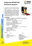
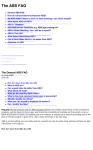
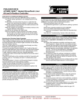
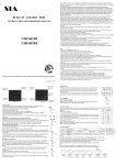
INSTALLATION INSTRUCTIONS
Honda NT700
Tour Performance HRA (Handlebar Relocation Adapter)
P/N: HR01053 Standard Version
IMPORTANT:
PLEASE GIVE CUSTOMER ENCLOSED INFORMATION!
Thank you for your purchase of our HeliBars®. They are designed to increase your long distance comfort and improve the handling of your sport motorcycle, and we feel confident you
will enjoy them.
Your HeliBars are designed to fit your motorcycle with little to no modifications needed
to your stock cables and hydraulic lines. In order to achieve this fit, we do not simply increase
the height at the fork tube/triple clamp area. If we were to mirror the angle of your stock handlebars, the HeliBars would not fit and clear your stock equipment, and lock to lock steering
clearance would be impossible.
If you hold up the HeliBars and compare it to your stock handlebar, the difference may
not be readily evident. One test we can suggest is to take your stock handlebar, and the corresponding HeliBars, and set them both on a flat surface. You can see the angle difference. Then
install the left HeliBars, following the instructions. Walk around the front of your bike and look
through the windshield. You should see a noticeable difference between your stock handlebar
and the HeliBars. Finish the installation, and try them out. We think you’ll like them!
HeliBars INSTALLATION
IMPROPER INSTALLATION COULD RESULT IN SERIOUS INJURY OR DEATH.
HAVE A QUALIFIED MECHANIC INSTALL YOUR HeliBars.
IF WE HAVE NOT INCLUDED SPECIFIC INSTRUCTIONS FOR YOUR MOTORCYCLE, THEN THE INSTALLATION IS SIMPLY A REVERSAL OF THE DISASSEMBLY PROCESS. **NOTE THE LOCATION OF LINES AND CABLES. BE SURE TO
CLEAN THE FORK TUBES BEFORE INSTALLATION!!
!! CAUTION !! MAKE SURE THE HeliBars ARE FULLY SEATED. TIGHTEN BAR
END DAMPER WEIGHTS FIRMLY. AFTER INSTALLATION, MOVE BARS LOCK
TO LOCK AND CHECK CLEARANCE OF: 1.CABLES 2. HYDRAULIC LINES
3.WIRES 4.FAIRING 5.FUEL TANK. TORQUE ALL HARDWARE TO MANUFACTURER’S SPECIFICATIONS.
IF YOU HAVE INSTALLATION QUESTIONS, PLEASE CALL 1-800-859-4642.
HELI MODIFIED, INC. ASSUMES NO LIABILITY FOR ANY INJURY OR LOSS OF
PROPERTY WHICH MAY RESULT FROM IMPROPER INSTALLATION OR USE OF
ANY HeliBars.
Honda NT700 Handlebar Relocation Adapter Installation Instructions
~ PO Box 638 ~ 20 Industrial Way ~ Cornish, ME 04020
Toll Free: 800-859-4642 ~ Int’l: 207-625-4642 ~ Fax: 207-625-3024 ~ www.HeliBars.com
Page 2
Updated: 7/7/11
WARRANTY / RETURN POLICY
We make every effort to build a quality product so you can fully enjoy your riding
experience. Thank you for your order.
HeliBars® may be returned for defects in materials and workmanship within one year from the date of
shipment to the original purchaser, in which event the purchaser may receive a replacement set of HeliBars.
If within thirty (30) days of the shipping date you are not satisfied for any reason, you can return the HeliBars. Return policy is valid for original purchaser only. If HeliBars are purchased from a vendor other
than Heli Modified, Inc., customer must contact vendor where purchased regarding returns. Refund will
be extended to original purchaser only. There are no other warranties which extend beyond this.
Conditions of this 30 day return policy:
1.
2.
3.
4.
5.
6.
Bars must not be used as a tie down point. (See attached ‘Trailering Instructions’).
Bars cannot be damaged, dented, or altered in any way.
Bars cannot be overtorqued.
Refund will be for product purchase price only, and credited to original purchaser
only.
Product must be returned with all original equipment, documents and in original
packaging. There must be no physical damage caused by the customer or by carrier.
A Return Authorization Number must be obtained from us before you return the product.
We reserve the right to charge a re-stocking fee of up to 25% if the above criteria are not met.
THERE ARE NO FURTHER EXPRESS OR IMPLIED WARRANTIES INCLUDING,
BUT NOT LIMITED TO, IMPLIED WARRANTIES OF MERCHANTABILITY OR
FITNESS FOR A PARTICULAR PURPOSE. By accepting this product, the consumer
agrees to arbitrate and litigate any controversy in the State of Maine, and under the laws
of the State of Maine.
HELI MODIFIED INC. ASSUMES NO LIABILITY FOR ANY INJURY OR LOSS OF
PROPERTY WHICH RESULT FROM IMPROPER INSTALLATION OR USE OF ANY
HELI BARS. ALL HELI MODIFIED, INC. PRODUCTS SHOULD BE INSTALLED BY
A QUALIFIED MECHANIC. IMPROPER INSTALLATION MAY CAUSE DEATH OR
INJURY.
Ride Safe and Enjoy!
Honda NT700 Handlebar Relocation Adapter Installation Instructions
~ PO Box 638 ~ 20 Industrial Way ~ Cornish, ME 04020
Toll Free: 800-859-4642 ~ Int’l: 207-625-4642 ~ Fax: 207-625-3024 ~ www.HeliBars.com
Page 3
Updated: 7/7/11
Honda NT700 Handlebar Relocation Adapter
Installation Instructions
Part # HR01052 Pilot Version – 1” Ram Ball & Powerlet Socket
Part# HR01053 Standard Version – Pre-drilled Hole to Accept Ram Ball
2 1/2” Taller ~ 3 1/2” Rearward ~ 4.163” Net Gain to Rider
________________________________________________________________________
WARNING: IMPROPER INSTALLATION COULD RESULT IN SERIOUS INJURY OR DEATH.
HAVE A QUALIFIED MECHANIC INSTALL YOUR HELIBARS®.
ATTENTION:
The use of a factory service manual is highly recommended as installation of this product requires a great
deal of body work be removed to access some components.
CAUTION:
These instructions are intended to guide a mechanic of good mechanical skill or better with experience
changing motorcycle hydraulic lines and control cables (clutch & throttle).
DANGER:
Failure to follow all cautions could result in a vehicle that is unsafe to ride. Failure of the installer to
properly install this kits front brake line and successfully remove all air (bleed) from the system will result in little or NO front brakes. Failure to follow all caution could result in serious injury or death.
LEAVE STOCK HANDLEBARS BOLTED TO THE FORKS UNTIL ASKED TO REMOVE.
1. Remove damper weight from right side of handle bar. Hold the body (large diameter) still while loosening
the screw with 5 mm hex. Leave left side in place. (See Photo #1)
2. Remove saddle. Open left saddlebag, push seat latch lever rearward and lift seat at it’s rear and pull back.
3. Remove rubber molding from rear of fuel tank.
4. Open left and right fairing storage pocket lids, wiggle back to disengage cover from hinge rod and remove
from bike. (See Photo #2)
5. Loosen and remove the two forward fuel tank screws. Use an 8mm socket. (See Photo #3) DO NOT lose
washers or spaces.
6. Remove fairing top covers (which partially covers forward side of fuel tank.)
Page 4
A. Loosen and remove the two screws from the fairing storage pockets forward mount. (See photo #4)
B. Loosen and remove the single rear screw. Use a M4 (See photo #5)
C. Lift the left side fairing top cover up slightly, pull outward on the rear section to release the tab and
release the throttle cables from the groove in the lower, forward corner and lift the cover off the fairing.
There is a piece of velcro attached between the cover and the fuel tank. This velcro will resist
removal and makes an awful sound when the cover releases. (See photo #6) This shows the velcro
and the tab which hold the rear of the fairing covers in place.
D. Remove radiator side grill panels by loosening and removing the single screw (phillips) as shown in
Photo #7. Pull back and wiggle up and down to disengage tabs.
7.
Remove the Left and Right bolts that attach the fairing mounts to the sides of the fuel tank. Use a
10mm socket. Use caution not to lose the washer/spacer. (See Photo #8.)
8.
A. Remove the factory clutch cable. Loosen the two lock nuts on top of the engine case where the cable
attaches. Remove cable end from clutch arm bracket. (Not shown) Right side of engine see (Photo #9)
B. Remove clutch cable from clutch lever. Turn the adjuster and it’s lock nut so the open grooves are
facing forward, pivot cable forward 90 degrees, push down and remove barrel end of cable form clutch
lever. (See Photo#10)
C. Carefully remove cable from the bottom while pushing down on the top half. Note the clutch cables
position behind the radiator. DO NOT install the new clutch cable at this time.
9.
Remove upper front brake hydraulic line between the master cylinder and the lower junction block
located on the front of the lower triple clamp.
A. Remove the clamp and bolt that holds the front brake hydraulic line to the upper triple clamp.
(See Photos 11 & 12)
B. Remove the front brake resevoir cover and drain the master cylinder. (CAUTION: Brake Fluid will
damage paint and plastic) Place a rag under the master cylinder at the banjo fitting, loosen the banjo bolt
and remove the banjo bolt and the line from the master cylinder. Use a 12mm wrench or socket. Catch
any draining brake fluid with a rag. Place a clean rag in the threaded master cylinder hole.
(See Photo #13)
C. Follow the line down to the junction block on the bottom triple clamp. There are two banjo fittings
with their banjo bolts facing forward (view from the front). The right side is the one to remove. Loosen
the banjo bolt with one hand and catch the fluid with a rag in the other hand. When the fluid is finishing
draining, remove the line. Temporarily place a small bit of a very clean lint free rag in the junction
block threaded hole. (See Photo #14).
Honda NT700 Handlebar Relocation Adapter Installation Instructions
~ PO Box 638 ~ 20 Industrial Way ~ Cornish, ME 04020
Toll Free: 800-859-4642 ~ Int’l: 207-625-4642 ~ Fax: 207-625-3024 ~ www.HeliBars.com
Page 5
Updated: 7/7/11
10.
Remove stock throttle cables.
A. Lift the tank from the front (tank will pivot in the rear rubber mount) and carefully prop it up using a
bungee cord attached to the rear grab rail etc. (Less fuel in the tank is a good idea at this time
(See Photo #15)
B. Remove rubber elbow by first squeezing the two hose clamps and moving them away from the clamp
area. Wiggle and remove from the nipples. (See Photo #16)
C. Loosen and move single clamp from inner hose and remove from nipple. This hose can be
positioned out of the way beside and below the frame rail. (See arrow on Photo #16)
Pull valve with the two nipples on it straight out from it’s holder and place on top of bracket.
(See Photo #17)
D. Remove the pull (top) and push (bottom) throttle cables from their mounting bracket. Loosen the
pull cables lock nut to the left of the bracket and thread it back enough to allow the cable to be angled
and removed from bracket. Repeat on the push cable by turning the larger hex portion until the cable is
loose enough to be removed from bracket. (See Photo #18) Use a 10mm wrench.
E. Remove cable ends from throttle body pulley.
F. Note the locations of the throttle cables as they are positioned on the bike. A photo taken at this point
could aid in reassembly. Pull the cables free from the frame and triple clamp and let them rest on the left
side of the bike.
G. Find the micro switch located beneath the front brake master cylinder and carefully remove the two
spade connectors with needle nose pliers. (See Photo #19)
H. Loosen top (pull) throttle cable elbow lock nut then loosen and remove lower (push) cable threaded
sleeve from the throttle housing. (See Photo #20) Use a 17mm wrench.
I. Loosen the screws that hold the two halves of the throttle housing together and remove. The two
screws can be found by looking at the bottom half of the throttle housing. One in front, one in back.
Push down on the throttle housing. One in front, one in back. Push down on the lower throttle housing
half, dislocate the locating pin from the hole in the handlebar tube and carefully slide the throttle off the
handlebars. Remove the pull and the push cable ends from the throttle sleeve. (See Photo #21) It may
be necessary to temporarily remove the reusable cable ties that are holding the throttle control housing
wire loom to the handlebar to allow throttle to slide off the end of the bar.
J. Pull the lower (push) cable from housing. Un-thread the upper pull cable and remove the housing.
11.
Install longer Barnett throttle cables:
A. Install the upper (pull) cable into the throttle housing by carefully threading the elbow clockwise 6
full turns. Temporarily lightly tighten lock nut. (See Photo #22)
Honda NT700 Handlebar Relocation Adapter Installation Instructions
~ PO Box 638 ~ 20 Industrial Way ~ Cornish, ME 04020
Toll Free: 800-859-4642 ~ Int’l: 207-625-4642 ~ Fax: 207-625-3024 ~ www.HeliBars.com
Page 6
Updated: 7/7/11
B. Install lower (push) cable by turning the threaded sleeve into housing. Do not bother tightening at
this time. (See Photo #23) Just let the cables lay on the right side of the fairing for now.
C. Install throttle cable barrel ends into throttle sleeve. Use cable lubricant provided with cables. (See
Photo #24)
D. Position the sleeve into the throttle housing halves by first pulling both cables at the opposite end
to get rid of the extra cable slack. Slide throttle assembly over handlebar end and engage lower locating
pin back into the locating hole in the handlebar tube, close both halves together and reinstall the screws
putting the longer screw in the rear and the shorter one in front and tighten. If halves do not come
together easily, either the throttle sleeve is in the wrong position or there is cable slack inside the
housing.
E. Re-attach micro switch connectors. (See Photo #19)
F. Re-install right damper weight. Tighten.
12.
A. Remove ALL the wiring connectors from their holders located on the inside of the left side of the
fairing. (See Photo #26) The connectors are released from their stock possition to allow additional
slack of the control housing wire looms going up the right and left side of the handlebars.
B. Group the connectors together as shown in (Photo #27) with the upper connectors cable tied to the
wiring harness and the lower pair cable tied to the tubing shown.
13.
A. Place a large rag etc. over the windshield. Remove the four handlebar clamp bolts and clamp. Use a
12mm socket. Carefully tie or bungie cord the handlebars up against the back of the windshield to keep
them out the way.
*** If the Pilot version is being installed, it is best to wire the Powerlet at this time.
See separate instructions.***
B. Clean the handlebar mounting area and install the HeliBar Handlebar Relocation Adapter with the
two 30mm screws in the forward holes and the two 40mm screws. Torque all four screws to 12 ft. lbs.
(See Photo #28)
14.
Mount the handlebars.
A. Release the handlebars and carefully position them over the new mounting area of the HeliBars
Adapter, making sure the knurling is equally positioned on the left and right sides.
B. Place the handlebar clamp in position. Make sure the small punch marks are in the front and install
the stock clamp hardware. With the saddle remounted adjust bars to the more comfortable angle and
torque the two forward bolts first to 12 ft lbs. followed by the rear two. Remove seat.
Honda NT700 Handlebar Relocation Adapter Installation Instructions
~ PO Box 638 ~ 20 Industrial Way ~ Cornish, ME 04020
Toll Free: 800-859-4642 ~ Int’l: 207-625-4642 ~ Fax: 207-625-3024 ~ www.HeliBars.com
Page 7
Updated: 7/7/11
15.
Feed the throttle cables through the wire guide, back under the top triple clamp and over the left frame
rail as per the stock cables. Make sure they are positioned below the electrical fitting mounted to the
front of the air filter.
16.
Attach throttle cables to throttle body.
A. Install the push cable first in the lower position. The push cable has the long hex with the single lock
nut. Use the lubricant and cover the barrel and the cable that is exposed. Engage the barrel in the lower
hole on the throttle body pulley and position the cable into the mounting bracket. Lock nut must be
loose for the fitting to engage the bracket. Tighten the lock nut by hand then tighten the fitting by
turning the long hex with a wrench. (See Photo #18)
B. Install the pull cable as per above, lubricate cable and barrel, engage into top hole and install in
bracket. Tighten left lock nut after adjusting nuts to provide equal threads on left and right sides of
fitting.
C. Re-install valve with nipples into bracket followed by hoses and clamps. (See Photo #15 & #16)
D. Adjust throttle cables by carefully turning the pull and push cables adjusters at the throttle housing
elbows. Leave a little slack on both cables and make sure throttle opens completely and returns to idle
position smoothly. There should be a little slack felt in the grip when turned from idle position. Tighten
lock nuts.
E. Return fuel tank to normal position.
17.
Mount the new Galfer upper hydraulic brake line.
A. The 90 degree fitting mounts to the bottom. Position the brake line as shown in Photo #29, with
one new washer on both sides of the banjo fitting. Hold the line in position and tighten to 12-14 ft lbs.
Attach the upper end to master cylinder using washers left and right of the banjo fitting and tighten bolt
to 12-14 ft lbs. Keep line in position as shown in Photo #30.
B. Remove stock upper brake line grommet as shown in Photo #31. This will protect the original line if
bike is ever returned to stock. Protect the line by using a spade screw driven behind the grommet.
C. Place the grommet over the Galfer brake line and close the metal clamp arount it. Bolt clamp as per
original. (See Photo #32)
D. Place one cable tie provided around the lower right fork tube the brake line. Tighten and cut off
excess. See arrow on Photo #29.
18.
Install Barnett clutch cable.
A. Feed the line from the bottom making sure the line feeds up behind the radiator but away from the
Honda NT700 Handlebar Relocation Adapter Installation Instructions
~ PO Box 638 ~ 20 Industrial Way ~ Cornish, ME 04020
Toll Free: 800-859-4642 ~ Int’l: 207-625-4642 ~ Fax: 207-625-3024 ~ www.HeliBars.com
Page 8
Updated: 7/7/11
exhaust pipe. Line should come up below and in front of the lower triple clamp on the right side of the
fork as per stock.
B. Remove outer lock nut. (Photo #33)
C. Place clutch cable adjuster into bracket, slide the outer lock nut over the end of the cable and thread
it onto adjuster. (See Photo #34)
D. Attach upper clutch cable to clutch lever. Position clutch cable in front of throttle cables.
(See Photo #10) Use some lubricant provided.
E. Attach clutch cable to clutch arm lever on engine. Adjust lower cable adjuster first and make fine
free play adjustments up at the clutch lever adjuster. Leave a small bit of free play. Make sure to tighten
lock nuts below and thumb lock nut at clutch lever adjuster.
19.
Make sure throttle cables and clutch cable are positioned correctly as shown in Photo #35 & 36.
Throttle cable are behind clutch cable.
20.
Position throttle cable elbows as shown in Photo #36 and tighten. Remember you are tightening parts
into plastic so just snug them up.
21.
Re-install all body work by reversing steps 7 through 2. When installing top left fairing cover, make
sure throttle cables fit the cut out as shown in Photo #37. Power wires for the Pilot models will also fit
through this opening.
22.
Fill master cylinder with brake fluid (DOT 4) and bleed all calipers.
23.
Start vehicle in neutral and make sure revs climb then return to normal idle when throttle is released.
24.
Double check that everything has been re-tightened or torqued as requested in these instructions before
riding machine.
For questions regarding installation please call 1-800-859-4642 or email [email protected]
WARNING: IMPROPER INSTALLATION COULD RESULT IN SERIOUS INJURY
OR DEATH. HAVE A QUALIFIED MECHANIC INSTALL YOUR HELIBARS®.
!!!CAUTION!!! BARS MUST BE TORQUED TO SPECIFIED VALUES. THEY MUST
NOT BE OVERTORQUED. OVERTIGHTENED HARDWAR CAN LOSE INTEGRITY.
HELI MODIFIED, INC. ASSUMES NO LIABILITY FOR ANY INJURY OR LOSS OF
PROPERTY WHICH MAY RESULT IN IMPROPER USE OF ANY HELIBARS.
Honda NT700 Handlebar Relocation Adapter Installation Instructions
~ PO Box 638 ~ 20 Industrial Way ~ Cornish, ME 04020
Toll Free: 800-859-4642 ~ Int’l: 207-625-4642 ~ Fax: 207-625-3024 ~ www.HeliBars.com
Page 9
Updated: 7/7/11
Photo # 4
Photo # 3
Photo # 2
Photo # 1
Honda NT700 Handlebar Relocation Adapter Installation Instructions
~ PO Box 638 ~ 20 Industrial Way ~ Cornish, ME 04020
Toll Free: 800-859-4642 ~ Int’l: 207-625-4642 ~ Fax: 207-625-3024 ~ www.HeliBars.com
Page 10
Updated: 7/7/11
Photo # 8
Photo # 7
Photo # 6
Photo # 5
Honda NT700 Handlebar Relocation Adapter Installation Instructions
~ PO Box 638 ~ 20 Industrial Way ~ Cornish, ME 04020
Toll Free: 800-859-4642 ~ Int’l: 207-625-4642 ~ Fax: 207-625-3024 ~ www.HeliBars.com
Page 11
Updated: 7/7/11
Photo # 12
Photo # 11
Photo # 10
Photo # 9
Honda NT700 Handlebar Relocation Adapter Installation Instructions
~ PO Box 638 ~ 20 Industrial Way ~ Cornish, ME 04020
Toll Free: 800-859-4642 ~ Int’l: 207-625-4642 ~ Fax: 207-625-3024 ~ www.HeliBars.com
Page 12
Updated: 7/7/11
Photo # 16
Photo # 15
Photo # 14
Photo # 13
Honda NT700 Handlebar Relocation Adapter Installation Instructions
~ PO Box 638 ~ 20 Industrial Way ~ Cornish, ME 04020
Toll Free: 800-859-4642 ~ Int’l: 207-625-4642 ~ Fax: 207-625-3024 ~ www.HeliBars.com
Page 13
Updated: 7/7/11
Photo # 20
Photo # 19
Photo # 18
Photo # 17
Honda NT700 Handlebar Relocation Adapter Installation Instructions
~ PO Box 638 ~ 20 Industrial Way ~ Cornish, ME 04020
Toll Free: 800-859-4642 ~ Int’l: 207-625-4642 ~ Fax: 207-625-3024 ~ www.HeliBars.com
Page 14
Updated: 7/7/11
Photo # 24
Photo # 23
Photo # 22
Photo # 21
Honda NT700 Handlebar Relocation Adapter Installation Instructions
~ PO Box 638 ~ 20 Industrial Way ~ Cornish, ME 04020
Toll Free: 800-859-4642 ~ Int’l: 207-625-4642 ~ Fax: 207-625-3024 ~ www.HeliBars.com
Page 15
Updated: 7/7/11
Photo # 28
Photo # 27
Photo # 26
Photo # 25
Honda NT700 Handlebar Relocation Adapter Installation Instructions
~ PO Box 638 ~ 20 Industrial Way ~ Cornish, ME 04020
Toll Free: 800-859-4642 ~ Int’l: 207-625-4642 ~ Fax: 207-625-3024 ~ www.HeliBars.com
Page 16
Updated: 7/7/11
Photo # 32
Photo # 31
Photo # 30
Photo # 29
Honda NT700 Handlebar Relocation Adapter Installation Instructions
~ PO Box 638 ~ 20 Industrial Way ~ Cornish, ME 04020
Toll Free: 800-859-4642 ~ Int’l: 207-625-4642 ~ Fax: 207-625-3024 ~ www.HeliBars.com
Page 17
Updated: 7/7/11
Photo # 36
Photo # 35
Photo # 34
Photo # 33
Honda NT700 Handlebar Relocation Adapter Installation Instructions
~ PO Box 638 ~ 20 Industrial Way ~ Cornish, ME 04020
Toll Free: 800-859-4642 ~ Int’l: 207-625-4642 ~ Fax: 207-625-3024 ~ www.HeliBars.com
Page 18
Updated: 7/7/11
Photo # 37
Honda NT700 Handlebar Relocation Adapter Installation Instructions
~ PO Box 638 ~ 20 Industrial Way ~ Cornish, ME 04020
Toll Free: 800-859-4642 ~ Int’l: 207-625-4642 ~ Fax: 207-625-3024 ~ www.HeliBars.com
Page 19
Updated: 7/7/11
IMPORTANT INFORMATION
ABOUT POWDER COATED HELIBARS
HeliBars® are finished with a polyester powder coating from Morton Powder Coating
Company (www.mortonpowder.com) The polyester is recommended for outdoor use because
of it’s excellent UV resistant quality; if we were to use an epoxy it would tend to fade and chalk
pretty quickly when exposed to sunlight and UV rays.
Care must be taken during installation because the finish can be scratched by the sharp
surfaces of the controls and master cylinder clamps. When mounting the master cylinders to
bars, do not let them move around the bars with the caps loose. Mount them in the proper position and hand tighten the screws until final adjustments are made; in this way you will lessen the
possibility of scratching.
NOTE: Powder coat finish is not indestructible, there are chemicals which may react
negatively when applied to finish. Brake fluid may cause deterioration of the finish. We do not
recommend the use of acetone or similar chemicals for cleaning purposes. We would recommend the use of an over-the-counter adhesive remover (such as Goo Gone) for the removal of
any extraneous material. Please read labels directions for any cleaning/polishing product before
use. If you have any questions regarding the use of any over-counter-products with the HeliBars, please call us before applying them to the powder coated finish.
If care is taken during installation, your HeliBars will continue to look as good as when
they were new. They will look great for years to come with a bit of wax and careful cleaning.
Thank you for your purchase, ride safe and enjoy!
Sincerely,
Harry Eddy, President
~ PO Box 638 ~ 20 Industrial Way ~ Cornish, ME 04020
Toll Free: 800-859-4642 ~ Int’l: 207-625-4642 ~ Fax: 207-625-3024 ~ www.HeliBars.com
Trailering with HeliBars®
HeliBars clip ons and handlebars must not be used as the
primary holding points for tie downs while trailering. As with your stock bars applying
extreme force to the ends of the bars can bend the bars or rotate them on their mounts.
Use a wheel chock and pull the machine down and forward using soft ties or similar, attached to the lower triple clamp.
Bars should only be used as secondary attachment points to steady the motorcycle from
lateral sway.
Failure to follow these guidelines can cause damage to the bars and the motorcycle, and
may also void our warranty.
Honda NT700 Handlebar Relocation Adapter Installation Instructions
~ PO Box 638 ~ 20 Industrial Way ~ Cornish, ME 04020
Toll Free: 800-859-4642 ~ Int’l: 207-625-4642 ~ Fax: 207-625-3024 ~ www.HeliBars.com
Page 21
Updated: 7/7/11