1
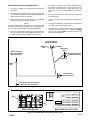
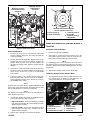
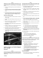
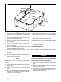
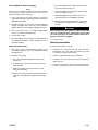
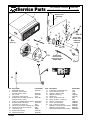
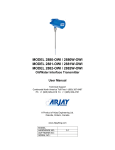
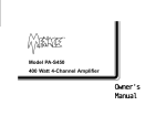
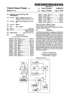
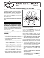
INSTRUCTIONS
®
-J03052
Rev 9-9-03
Kit Number 76350-04
FLHT 2004 AND LATER RADIO/CD KIT WITH AMP
General
T27 TORX screws, upper fairing
i03413
This Radio/CD with amplifier is designed for installation on
2004 and later FLHT/C/CI® and FLTR/I® model motorcycles.
This kit will fit 1998-2003 FLHT models with separate purchase of Power Connection Kit (Part Number 70663-04).
2
3
1
NOTE
This kit is designed to power 2 speakers only. It will not work
with 4 speaker systems.
40
30
20
10
0
This kit requires installing Antenna Kit (Part Number 7630698, sold separately) available from your Harley-Davidson
dealer.
50 60 70
MPH
30
80
90
100
110
120
40
50
60
20
10
0
CE
D
HAR RTIFIE SON
LEY-DAVID
70
RPMx100
HAR
80
N
LEY-DAVIDSO
UNLOCK
See the Service Parts illustration for kit contents.
1WARNING
A Service Manual is required for correct installation of this
kit. The rider’s safety depends upon correct installation of
this kit. Read this Instruction Sheet and the appropriate
Service Manual sections before proceeding. If the procedure is not within your capabilities or you do not have the
correct tools, have your Harley-Davidson dealer perform the
installation. Improper installation of this kit could result in
death or serious injury.
NOTE
A Service Manual for your motorcycle is available at your
Harley-Davidson Dealer.
5
4
6
7
T25 TORX screws, lower fairing
Figure 1. Removing Outer Fairing Fasteners
Install the Radio/CD with Amp
IMPORTANT
Copy the serial number from the label, located on top of the
radio chassis, before installing the radio. The serial number
must be included on the warranty form.
Outer Fairing Removal
NOTE
Connector numbers in brackets (for example, [27]) correspond to the connector numbers in the Service Manual
wiring diagrams.
1.
Follow instructions in applicable Service Manual and
remove seat.
1.
2.
Follow instructions in applicable Service Manual and
remove the Maxi-Fuse.
3.
See Figure 1. Remove the outer fairing and windshield:
NOTE
To assist installation, apply soapy water to the nose seal,
then gently rock the radio back and forth while inserting the
radio into the fairing.
Installation
a. Remove the TORX® screws (1, 2, 3) from the outer
fairing to remove the windshield.
2.
Tilt the back of the radio up 45 degrees. Gradually push
the radio nose seal into the hole in the inner fairing
while lowering the back of the radio. Check that the
nose seal is not distorted, compressed, or pinched.
3.
Fasten the radio to the inner-fairing brackets using the
four screws and washers from Step 4 in Outer Fairing
Removal. Torque the screws to 45–60 in-lbs (5.0–6.7
Nm).
4.
See Figure 4. Plug the radio-antenna cable connector
into the back of the radio. Tuck excess cable under the
right corner of the radio.
5.
See Figure 4. Plug the 23-place connector [27] from the
existing (Original) wiring harness into the BLACK connector on the back of the radio.
b. Remove the TORX screws (4, 5, 6, 7) from the inner
fairing. Turn the handlebar to access screws 6 and 7.
c. Tilt the outer fairing toward the front, then squeeze
the two external tabs to remove the wire connector
from the back of the headlamp assembly.
d. Lift the fairing and headlamp assembly from the
motorcycle.
4.
Remove the four screws fastening the sides of the center storage box to the inner-fairing brackets. Save the
screws for installation.
Hold the radio between the support brackets with the
radio nose seal in position over the hole in the fairing.
1 of 7
Install Radio/CD Harness Supplied with Kit
5.
See Figure 3. Route the Fuse/Relay Socket Terminal
toward the Fuse/Relay block on the right side of the
motorcycle. Firmly insert the socket terminal into the
back of the fuse cavity marked 2-H on the Fuse/Relay
Block.
6.
Obtain the fuse from kit and install into 2-H of the
Fuse/Relay Block.
Using cable straps from kit, attach the power and ground
wires to the main harness along the route.
7.
Remove and discard the existing Fuse/Relay Block
Cover.
NOTE
For 1998 to 2003 Models, skip Steps 5, 6, 7, and 8 and follow
installation instructions provided in Instruction Sheet for
Power Connection Kit (J03067, Part Number 70663-04).
8.
See Figure 3. Obtain the new (printed) Fuse/Relay block
cover and install onto Fuse/Relay block.
9.
See Figures 2 and 4. Return to the fairing assembly and
connect the overlay power harness 23-place [28] GREY
Socket to the 23-place GREY connector located on the
back of the Radio/CD unit.
1.
See Figure 2. Obtain the new radio/CD overlay harness
from the kit.
2.
From the fairing, route the power and ground wires back
to the battery compartment running the wiring parallel to
the main harness under the fuel tank.
3.
4.
Attach the Ground (Ring Terminal) to the Ground Post
near the middle of the frame. NOTE: Remove the nut,
install the ring terminal then tighten the nut securely.
i06032
Left Front Speaker
(Spade Connectors)
White/Pink
Wire
Pink Wire
White/Grey
Wire
(Socket Terminal)
Route To Fuse/Relay
Block Cavity 2-H
Right Front Speaker
(Spade Connectors)
Grey Wire
Power
Wire
23-Way Socket
Connector (Grey)
Ground Wire with Ring Terminal
Route to Frame Ground Post
Figure 2. Radio/CD Overlay Power Harness
i06033
H
10A
D
F
15A
15A
3
15A
15A
15A
15A
15A
15A
H
BRAKE
RELAY
15A
15A
B
10A
4
2-H
SPARE FUSES
1
A
C
E
G
J
MAIN FUSE BLOCK
2
15A
2
BRAKE
RELAY
P&A IGN
RADIO PWR
BATTERY
RADIO MEM
RADIO AMP
P&A
ACCESS.
CRUISE/BRK
HEADLAMPS
IGN
LIGHTS
INSTRUMENTS
MAIN FUSE BLOCK COVER
Figure 3. Fuse/Relay Block and Fuse/Relay Block Cover
-J03052
2 of 7
i06034
Black [27], 23-place
Interconnect Harness
Connector
Grey [28], 23-place
Audio Harness
Connector
2
i04641
1
1
4
3
The lower inboard mounting hole
for each speaker is not used.
1. Screw, 2-inch (2)
2. Spade connectors
3. 1-1/8-inch screw (1),
left speaker
4. 1-1/8-inch screw (1),
right speaker
Figure 5. Speaker Installation
Install the Antenna on Vehicles without a
Tour-Pak
Figure 4. Radio Connections
Install the Speakers
1.
2.
3.
4.
Remove the three screws fastening the right-side
speaker adapter and grill to the fairing. Discard the
screws and adapter.
See the Service Parts illustration. Align the holes in the
speaker with those in the new adapter. Position the
speaker spade contacts at the top of the adapter, the
top being the thickest edge. Snap the speaker into the
adapter.
See Figure 5. Install two 2-inch screws at the top of the
speaker to fasten the speaker adapter assembly to the
inner fairing. Torque the screws to 22–28 in-lbs
(2.5–3.2 Nm).
Fasten the bottom of the speaker and the fairing support brace using one 1-1/8 inch screw in the speaker’s
lower-outboard mounting hole. Torque the screw to
35–50 in-lbs (4.0–5.7 Nm).
Install the Antenna Bracket
1.
Remove the right-side saddlebag.
2.
See Figure 6. Fasten the antenna bracket (5) to the
right fender-support bracket using two 5/16-18 x 5/8inch screws (9) and lockwashers (8) from the kit.
NOTE
If a saddlebag guard or rail is mounted at the lower hole in
the support bracket, use the 5/16-18 x 7/8-inch screw (10) to
fasten the antenna bracket and saddlebag guard to the support bracket.
3.
Tighten the mounting screws to 19 ft-lbs (26 Nm).
Fasten the Antenna to the Antenna Base
1.
See Figure 6. Screw the antenna (sold separately) onto
the antenna base assembly (2) and tighten the set
screw in the antenna to secure it to the base.
5175
NOTE
Speaker wires from main harness (Original Equipment) will
not be used. Using electrical tape, thoroughly tape the ends
then tie wrap the wires so they are out of the way.
1
2
NOTE
The speaker mounting hole on the lower inboard side of
either speaker is not used.
5.
3
Cable
strap
5
Connect the speaker wires (from the supplied harness)
to their respective-size spade connectors.
• Right-side speaker: Connect the white/grey and light
grey wires from the right side of the fairing to the rightspeaker spade connectors.
• Left-side speaker: Connect the white/pink and pink
wires from the left side of the fairing to the leftspeaker spade connectors.
6.
4
Repeat steps 1 through 5 to install the left speaker.
-J03052
7
6
1.
2.
3.
4.
Antenna
Antenna base assy.
Nut, 1/2-20
Lockwasher, int. tooth
5.
6.
7.
8.
8
Bracket
Antenna cable
Lockwasher (2)
Screws (2)
Figure 6. Antenna Mounting
3 of 7
NOTE
Tighten the set screw holding the antenna mast to the
antenna base assembly. The antenna set screws have metric threads (M4-0.7 x 3 mm) and require a 2.0 mm Allen®
wrench.
2.
Thread one of the large nuts (3) onto the antenna base
assembly.
3.
Insert the antenna base through the large, internal-tooth
lockwasher (4) and hole in the antenna mounting bracket (5).
4.
Fasten the other large nut (3) to the antenna base to
secure the base to the bracket. With a wrench on the
upper nut, tighten the lower nut to 40 in-lbs (4.5 Nm).
Connect the Antenna Cable
NOTE
The measurements in this procedure refer and apply to the
lower half of the Tour-Pak only and do not involve or include
measurements from or on the Tour-Pak lid.
1.
See Figure 8. Measure the width to find the center of
the Tour-Pak outside-rear wall.
2.
Fasten a 2-inch wide strip of masking tape, vertically
from top to bottom, on the outside back center of the
Tour-Pak.
3.
Repeat Step 1 to mark the Tour-Pak vertical center on
the top and bottom of the tape strip.
4.
Draw a vertical line on the tape from the top mark to the
bottom mark.
5.
From the drawn center line, measure 9-1/4 inch to the
left.
6.
At the 9-1/4-inch measurement, fasten a 2 inch wide
strip of masking tape vertically from the Tour-Pak top
edge to the horizontal middle of the Tour-Pak wall.
1.
Remove the left sidecover from the vehicle to reveal the
antenna cable.
2.
Cut the cable strap fastening the antenna cable to the
frame.
3.
Route the antenna cable to the right side of the vehicle
and foward of the luggage-rack mount.
7.
Repeat Step 5 to mark a vertical line on the masking
tape from Step 6.
4.
See Figure 6. Plug the antenna-cable connector into the
antenna base.
8.
Across the vertical line on the left tape strip, draw a
short horizontal line:
5.
Tighten the knurled nut on the antenna-cable connector
to secure the connector to the antenna base.
6.
7.
See Figures 6 and 7. Secure the antenna cable to the
vehicle using cable straps at the locations shown.
Install additional cable straps on the left side of the front
luggage-rack mount and as required to secure the
antenna cable.
a. 1-1/4 inch down from the Tour-Pak top edge, and
b. 1-1/2 inch down from the horizontal line drawn in
step 8a (2-3/4 inch from the Tour-Pak top edge)
9.
Mark the center of the crossed lines with a center punch
and drill 1/8-inch pilot holes in the Tour-Pak wall at the
marked points
10. From the outside of the Tour-Pak, drill the pilot holes
from Step 9 to a:
5176
• 17/32-inch hole through the TOP pilot hole
• 1/4-inch hole through the BOTTOM pilot hole
Cable straps
11. Remove the tape from the Tour-Pak.
NOTE
Some Tour-Paks are equipped with a 5/8-inch hole in the
bottom at the front-left side. This hole is for antenna-cable
routing. If your Tour-Pak does not have this hole, complete
Step 12. Otherwise, continue to the next section.
12. Drill an antenna-cable access hole:
a. Remove the Tour-Pak liner.
b. See Figure 1. Locate the pattern of eight 0.31-inch
diameter holes in the metal plate on the insidebottom of the Tour-Pak.
Figure 7. Cable Strap Locations
c. From the front left-hand hole, measure forward 1 inch
and left (outboard) 4 inch Mark this location.
Install the Antenna on Vehicles Equipped
with a Tour-Pak
d. Drill a small pilot hole at the marked location.
e. From the underside of the Tour-Pak, drill a 5/8-inch
hole from outside the Tour-Pak to the inside.
Preparation
NOTE
Install the antenna where indicated to avoid antenna interference when opening and closing the Tour-Pak lid. Install the
antenna base in the upper-left corner of the Tour-Pak outside-rear wall.
-J03052
Antenna Installation
1.
See the Service Parts Illustration. Place the gasket (12)
on the antenna-base assembly (5).
4 of 7
i01002a
1-1/4 inch
Center line
9-1/4 inch
17/32inch hole
1-1/2 inch
1/4-inch
hole
1 inch
5/8-inch
hole
4 inch
Figure 8. Drilling the Tour-Pak for Radio-Antenna Installation
2.
Place the base assembly, with the antenna-mast stud
facing upward, into the drilled holes on the back of the
Tour-Pak.
12. Plug the antenna-cable connector into the antenna
base. Allow enough cable that, when connected, the
cable rests flat on the inside bottom of the Tour-Pak.
3.
Place the reinforcement plate (13) on the antenna-base
assembly studs inside the Tour-Pak.
13. Tighten the knurled nut on the antenna-cable connector
to secure the connector to the antenna base.
4.
Place the ground cable (6) on the antenna-base assembly antenna stud.
14. Use cable straps to secure the antenna cable to the left
side of the Tour-Pak support.
5.
Fasten the antenna-base assembly, reinforcement
plate, and ground stud to the Tour-Pak using a lockwasher (4) and nut (3).
6.
Attach the other end of the ground cable to a mounting
bolt on the inside-bottom of the Tour-Pak.
7.
Install the screw (15) and small lockwasher (14) in the
bottom hole of the antenna base and from inside the
Tour-Pak.
8.
Screw the antenna (sold separately) onto the antenna
base assembly (2) and tighten the set screw in the
antenna to secure it to the base.
NOTE
Tighten the set screw holding the antenna mast to the
antenna base assembly. The antenna set screws have metric threads (M4 - 0.7 x 3 mm) and require a 2.0 mm Allen®
wrench.
15. Install a grommet in the 5/8 inch hole at the bottom-front
left side of the Tour-Pak.
Test the Sound System
NOTE
Before installing the outer fairing, test the radio/CD, antenna, and speakers.
1.
Turn the ignition to the OFF position.
1WARNING
Always connect the positive battery cable first. If the
positive cable should contact ground with the negative
cable installed, the resulting sparks may cause a battery
explosion resulting in death or serious injury.
2.
Connect the battery cables to the battery, positive cable
first.
Remove the left sidecover from the vehicle to reveal the
antenna cable.
3.
Refer to the SOUND SYSTEM manual in this kit to test
the sound-system operation.
10. Cut the cable strap fastening the antenna cable to the
frame.
4.
Troubleshoot the radio, CD, speaker, and antenna functions as needed. Otherwise, install the Tour-Pak liner
and continue to the next section.
9.
11. Route antenna cable along the Tour-Pak left-side support rack and up through the 5/8 inch hole in the bottom-front left side of the Tour-Pak.
-J03052
5 of 7
1998 to 2003 AVC Setup Procedures
e. Turn the handlebar to the left and start the next fairing screw below the fairing cap.
NOTE
This setup is not required for 2004 and later FLHT Models.
1998 to 2003 models require this procedure for the
Automatic Volume Control to function.
1.
f. Turn the handlebar to the right and start the fairing
screw on the opposite side.
g. Alternately tighten the four fairing screws on the
inner-fairing side to 45–55 in-lbs (5–6.2 Nm).
Press and hold any two preset buttons on the front
panel while turning the ignition/light switch from OFF to
IGNITION or ACCESS.
2.
Diagnostic Group 1 (d1), the first of several diagnostic
screens will appear in the LCD. Press the local/distant
(LO-DX) button to cycle through the diagnostic screens.
3.
Stop at the screen: Press 1 for 1998 to 2003 models.
Press 2 if your bike is MY2004 or later.
4.
Press Preset 1 button.
5.
After selecting the correct model year, repeatedly press
the LO-DX button until the receiver reverts back to normal radio operation.
h. On the front of the vehicle, tighten the outer fairing
screws below the windshield to 10–13 in-lbs (1.1 –
1.4 Nm).
1WARNING
After installing seat, pull upward on front of seat to be
sure it is in locked position. While riding, a loose seat
can shift causing loss of control, which could result in
death or serious injury. (00070a)
3.
Install the seat.
Warranty Information
Install the Outer Fairing
To activate the warranty for this kit:
1.
See Figure 1. Place the windshield in position on the
inner fairing. Align the slots in the windshield with the
threaded inserts.
1.
Complete the “Premium Sound System Warranty
Registration Card.” The radio serial number is located
on a label on top of the radio chassis.
2.
Install the outer fairing:
2.
Send the registration card to Radio Sound Inc.
a. Place the fairing and headlamp assembly on the
motorcycle
3.
Complete the “Premium Sound System Warranty/
Owner Record.”
b. Fasten the wire connector to the back of the headlamp assembly.
4.
Keep the “Premium Sound System Warranty/Owner
Record” and dated bill of sale for your warranty records.
c. On the outer fairing, loosely fasten three screws
below the windshield.
d. On the inner fairing, start the two fairing screws just
above the wind deflectors on both the left and right
side.
-J03052
6 of 7
®
Part Number 76350-04
Service Parts
Date 9/03
2004 Radio/CD with Amp Kit for FLHT
i06035
1
Antenna sold
separately
2
3
9
4
8
7
5
6
9 or 10
13
Stock
screw (4)
8
4
11
17
3
3
Stock cable
located under
vehicle left
sidecover
12
18
14
15
16
19
20
22
21
Item Description
1
Radio/CD with amp
2
Assembly, antenna base
(Includes items 3 and 4)
3
Nut, 1/2-20
4
Lockwasher, internal tooth
5
Antenna base assembly (Tour Pak)
(Includes items 3 and 4)
6
Cable assy, AM/FM antenna ground
7
Bracket, antenna mounting
8
Lockwasher, 5/16-inch (2)
9
Hex hd screw, 5/16-18 x 5/8 inch (2)
10 Hex hd screw, 5/16-18 x 7/8 inch
11
Cable strap (10)
12 Antenna base gasket
13 Reinforcement plate
-J03052
Stock cable
located inside
fairing, plugs into
back of radio
Part Number
76202-04
76335-87
76259-86
7129
76252-86
70465-86A
76153-95
7041
2882W
3991
10006
76255-86
76253-86
Item
14
15
16
17
18
19
20
21
22
23
–
–
–
Description
Lockwasher, #10 internal tooth
Screw, #10-32 x 3/4 inch
Grommet, antenna cable
Adapter, speaker (2)
Speaker (2)
Screw, 10-16 x 2 inch (4)
Screw, 10-16 x 1-1/4 inch (2)
Harness, overlay power
Cover, fuse/relay block
Fuse, 15 Amp (not shown)
Warranty, sound system (not shown)
Warranty card (not shown)
Sound System Manual (not shown)
Part Number
7118
2576
11486
77047-98
77178-01
2965
3639
71004-04
72005-04
72330-95
93745-02
99471-02
99464-03A
7 of 7