1
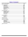
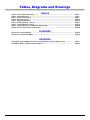
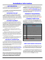
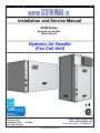
Installation and Service Manual
AHW-Series
Hydronic Air Handler
Model Size 65
Hydronic Air Handler
(Fan Coil Unit)
Maritime Geothermal Ltd.
P.O. Box 2555
Petitcodiac, N.B.
E4Z 6H4
Ph. (506) 756-8135
1-Sep-2015
Email: [email protected]
Web: www.nordicghp.com
Document Number: 001480MAN-01
ISSUE 04 DATE
Page :11-Sep-2015
001480MAN-01
!
SAFETY PRECAUTIONS
!
WARNING: Ensure all access panels are in place and properly secured before applying power to the unit.
Failure to do so may cause risk of electrical shock.
WARNING: Before performing service or maintenance on the heat pump system, ensure all power sources
are DISCONNECTED. Electrical shock can cause serious personal injury or death.
WARNING: Heat pump systems contain refrigerant under high pressure and as such can be hazardous to
work on. Only qualified service personnel should install, repair, or service the heat pump.
CAUTION: Safety glasses and work gloves should be worn at all times whenever a heat pump is serviced. A
fire extinguisher and proper ventilation should be present whenever brazing is performed.
CAUTION: Venting refrigerant to atmosphere is illegal. A proper refrigerant recovery system must be
employed whenever repairs require removal of refrigerant from the heat pump.
MODEL NOMENCLATURE
AHW—65—1—SDETV—xx
Series:
AHW = Hydronic Air Handler
Revision:
01, 02 etc.
Nominal Size:
65
Cabinet Orientation
V = Vertical
H = Horizontal
Voltage Code:
1 = 208/230-1-60 VAC
Fan Discharge Orientation
T = Top
S = Side
Air Coil:
S = Standard
Fan Type:
D = Direct Drive
Fan Motor:
E = ECM (Variable Speed)
APPLICATION TABLE
SIZE
VOLTAGE
FAN/CASE
65
1
SDETV
SDESH
REVISIONS
01
This manual applies only to the models and revisions listed in this table
001480MAN-01
Page 2
1-Sep-2015
Table of Contents
TABLES, DIAGRAMS & DRAWINGS: ……..……...………….……………………………………………………………… PAGE 4
INSTALLATION INFORMATION: …………………...………….………………………………………………………………
Unit description: …………………………………………………………………………………………………..…...
Unpacking the unit: …………………………………………………………………………………………………...
Optimum Placement: ………………………………………………………………………………………………….
Electrical Connections: ………………………………………………………………………………………………
Thermostat Requirements: …………………………………………………………………………………………..
Plumbing Connections: ………………………………………………………………………………………………
Zone Valve and/or Circulator: ……………………………………………………………………………………….
Airflow Selection: ……………………………………………………………………………………………………..
Fan Motor: ………………………………………………………………………………………………………………
Control Transformer : ……..…………………...……………………………………………………………………
PAGE 5
Page 5
Page 5
Page 5
Page 5
Page 5
Page 5
Page 5
Page 6
Page 6
Page 6
SIZING AND DUCTWORK: ………………...…………………………………………………………………………………… PAGE 7
Hydronic Air Handler Sizing: ………………………………………………………………………………………. Page 7
Duct Systems - General: …………………………………………………………………………………………….. Page 7
Duct Systems - Grill Layout: ………………………………………………………………………………………… Page 7
Thermostat Location: ………………………………………………………………………………………………… Page 7
Plenum Heater (Optional): …………………………………………………………………………………………… Page 8
Condensate Drain: …………………………………………………………………………………………………….. Page 8
Duct Sizing Guide: ……………………………………………………………………………………………………. Page 10
STARTUP PROCEDURE: ……………………………………………………………………………………………………….
Pre-start Inspection: ………………………………………………………………………………………………….
Unit Startup: …………..……………………………………………………………………………………………….
Startup Record: ……………….……………………………………………………………………………………….
Page 11
Page 11
Page 12
Page 13
GENERAL MAINTENANCE: ……………...…………………….……………………………………………………………… PAGE 14
TROUBLESHOOTING GUIDE: ………………………………….……………………………………………………………… PAGE 15
MODEL SPECIFIC INFORMATION: …………………..……………………………………………………………………….
Shipping Information: …………………………………………………………………………………………...……
Capacity Ratings: ………..………………..…………………………………………………………………………..
Electrical Tables: ………………………………………………………………………………………………………
Electrical Diagrams: ……………………...………………………………………..…………………………………
Dimensions—Vertical (SDETV): ……….…………..………………………………………………………….……
Dimensions—Horizontal (SDESH): ……….……….…………………………………………………………….…
PAGE 19
Page 19
Page 19
Page 20
Page 21
Page 22
Page 23
WARRANTY INFORMATION: ………………………………………………………………………………………………….. PAGE 24
1-Sep-2015
Page 3
001480MAN-01
Tables, Diagrams and Drawings
TABLES
Table 1 - Control Signal Description: …….………………………………………………………………..……....
Table 2 - Airflow Selections: ………………………………………………………………………………………...
Table 3 - Plenum Heater Sizing: …..………………………………………………..……………………………...
Table 4 - Duct Sizing Guide: ……………………………………………………...………………………………...
Table 5 - Shipping Information: ………...………………………..……….………….….……….………………...
Table 6 - Capacity Ratings - Heating: …………..……………………………………….………………………...
Table 7 - Capacity Ratings - Cooling: …………….…………………………………………………..…………...
Table 8 - Heat Pump Electrical Information (208/230-1-60): …..……………...….….………………………...
Table 9 - Plenum Heater Electrical Information: …..…………………………...…..….………………………...
Page 5
Page 6
Page 8
Page 10
Page 19
Page 19
Page 20
Page 20
Page 20
DIAGRAMS
Dimensions—Vertical (SDETV): ……….…………..……………………………………………………………… Page 22
Dimensions—Horizontal (SDESH): ……….……….……………………………………………………………… Page 23
DRAWINGS
001507CDG - Typical AHW-Series Duct and Condensate Connections (Modular Case): ……...……….
001853SCH - AHW-**-1--*DE** Schematic Diagram: ……………………...…………..…………….....……
001480MAN-01
Page 4
Page 9
Page 21
1-Sep-2015
Installation Information
UNIT DESCRIPTION
The AHW-Series unit is a high efficiency hydronic air handler that can be used to provide air heating or cooling from a
hydronic source, such as a water to water heat pump.
An electrically commutated (ECM) fan with several speed
options is standard. The motor has a soft start function for improved efficiency and reduced wear.
UNPACKING THE UNIT
When the air handler reaches its destination it should be
unpacked to determine if any damage has occurred during
shipment. Any visible damage should be noted on the carrier's
freight bill and a suitable claim filed at once. The air handler is
well constructed and every effort has been made to ensure that
it will arrive intact, however it is in the customer's best interest to
examine the unit thoroughly when it arrives.
OPTIMUM PLACEMENT
The air handler should be centrally located in the home
with respect to the conditioned space in order to provide even
air distribution. This design provides the utmost in economy and
comfort and usually can be accomplished in harmony with the
design of the home. A heating system cannot be expected to
produce an even warmth throughout the household when it is
located at one end of the structure and the warm air is
transmitted with uninsulated metal ductwork.
If possible the access panels should remain clear of
obstruction for a distance of two feet to facilitate servicing and
general maintenance.
Raising the air handler off the floor a few inches is generally
a good practice since this will prevent rusting of the bottom
panel of the unit. We recommend that the air handler be placed
on a piece of 2'' thick styrofoam. The styrofoam will smooth out
any irregularities in the cement floor.
The air handler comes equipped with an air-filter rack which
can be installed with the removable end (where the filter is inserted) on either side to facilitate changing the filter.
ELECTRICAL CONNECTIONS
Connect 208VAC or 230VAC single phase power to the
POWER terminal strip in the left side of the electrical box. If
using 208VAC, the control transformer wiring must be changed
as indicated in the CONTROL TRANSFORMER section of this
manual. Refer to TABLE 8 in the ELECTRICAL TABLES section of this manual for recommended wire and breaker sizes.
The Electrical Diagram is located in the Model Specific Information section of this manual
.
THERMOSTAT REQUIREMENTS
The AHW-Series unit is compatible with a single stage
thermostat or two stage thermostat if a plenum heater is installed. The schematic diagram on the electrical box cover provides a description of the signal connections as does TABLE 1.
PLUMBING CONNECTIONS
The unit is equipped with 1” brass FPT fittings for water
line connections. The ports are labeled INDOOR IN and INDOOR OUT. Connect the IN port to the supply header and connect the OUT port to the return header. Connect to the unit using standard plumbing techniques.
TABLE 1 - Control Signal Description
Signal
C
R
G
Y
W2
NOTE: A properly qualified electrician should be retained
to make the connections to the heat pump and associated
controls. The connections to the heat pump MUST CONFORM TO LOCAL CODES. Electrical code requirements
shall supersede the recommendations of this manual.
1-Sep-2015
24VAC Common (Ground)
24VAC Hot
Air recirculation mode (Fan low speed*)
Unit operation (Fan normal speed*)
Auxiliary heat / Emergency Heat
AR
24VAC Source for AR+ / AR– pins*
AR+
Airflow Adjustment*
ARAirflow Adjustment*
V
Zone Valve Common (optional)
V1
Zone Valve 24VAC (optional)
C
Plenum Heater Dry Contact (optional)
1
Plenum Heater Dry Contact (optional)
* Refer to TABLE 2 for airflow values.
The air handler has a concentric 1.093” / 0.875” knockout
for power supply connection to the electrical box, as well as one
spare knockout. There are two 1/2” openings with plastic grommets (grommet hole is 3/8”) in the upper section of the electrical
box, one for the thermostat connections, and one for the optional plenum heater connections.
A schematic diagram (SCH) can be found inside the electrical
box cover of the unit as well as in the Model Specific Information
section of this manual. The Electrical Tables in the Model Specific Information section and the SCH diagram contain information about the size of wire for the connections, as well as the
recommended breaker size.
Description
ZONE VALVE AND/OR CIRCULATOR
If there are multiple zones in the system then it is recommended that a zone valve be placed in the OUT line close to the
unit. A 24VAC powered zone valve may be connected to the V
and V1 terminals on the terminal strip for automatic operation.
If individual zone circulators are used instead of or in combination with zone valves, a 115VAC or 230VAC circulator may
be connected to the Zone Circulator terminal strip in the unit (if
applicable) for automatic operation. Ground may be connected
to the ground terminal of the POWER terminal strip.
Page 5
001480MAN-01
AIRFLOW SELECTION
The air flow can be set to six (6) different nominal levels by
via different combinations of the tap position of the Air Flow Select board and the jumper configuration of the AR terminals located in the electrical box. The airflow values are indicated in
TABLE 2. Units are shipped with the tap on the LOW position
and a jumper wire from AR to AR-, providing a default airflow
value of 1000cfm, select the desired tap during installation. Set
the airflow according to the desired capacity from the capacity
tables in the Model Specific Information section of this manual.
TABLE 2 - Airflow Selections
AIRFLOW
cfm (L/s)
1000 (472)
AIRFLOW SELECT
TAP
LOW
AR JUMPER
CONFIGURATION
AR to AR-
1200 (566)
1500 (708)
1800 (850)
2100 (991)
2400 (1133)
LOW
MED
HIGH
MAX
MAX
NONE
NONE
NONE
NONE
AR to AR+
FAN MOTOR
The unit is equipped with a direct drive ECM fan motor for
maximum efficiency. The motor features a soft start which further improves efficiency by eliminating inrush current and provides a smooth, quiet ramp up to speed . The motor will maintain the programmed air flow up to a maximum external static
value of 0.70” of water for the airflows indicated in TABLE 2.
CONTROL TRANSFORMER
The low voltage controls are powered by a 40VA class II
transformer. The transformer is impedance protected; if shorted
out and the impedance protection is activated, the transformer
will need to be replaced.
NOTE: For 208/230VAC-1-60 units, if connecting to 208VAC
power supply move the red wire connected to the 240 terminal of the transformer to the 208 terminal of the transformer.
001480MAN-01
Page 6
1-Sep-2015
Sizing and Ductwork
DUCT SYSTEMS - GRILL LAYOUT
HYDRONIC AIR HANDLER SIZING
Once the total heat loss has been calculated for the space,
the AHW-Series unit can be sized using the Capacity Ratings in
conjunction with the minimum expected entering liquid temperature. The hydronic air handler output must be able to match the
total heat loss at the selected entering water temperature in
order to provide a comfortable environment with minimal auxiliary heat. The tables can be found in the Model Specific Information section
DUCT SYSTEMS - GENERAL
Ductwork layout for a heat pump or air handler system will
differ from traditional hot air furnace design in the number of
leads and size of main trunks required. Air temperature leaving
the unit is normally 90º -105ºF (32-40ºC), much cooler than that
of a conventional warm air furnace. To compensate for this,
larger volumes of lower temperature air must be moved and
consequently duct sizing must be able to accommodate the
greater air flow without creating a high static pressure or high
velocity at the floor diffusers.
A duct system capable of supplying the required air flow is of
utmost importance. Maritime Geothermal Ltd. recommends that
the static pressure be kept below 0.2 inches of water total. In
some instances the number of floor diffusers will actually double
when compared to the number that would be used for a hot air
oil-fired furnace. Refer to TABLE 4 at the end of this section.
1. Generally allow 100 cfm for each floor grill.
2. All leads to the grills should be 6'' in diameter (28sq.in. each).
3. The main hot air trunks should be at least 75% of the square
surface area of leads being fed at any given point.
4. Return air grills should have a minimum of the same total
square surface area as the total of the supply grills.
5. The square surface area of the return trunks should equal
the square surface area of the grills being handled at any
given point along the trunk.
It is VERY IMPORTANT that all turns in both the supply
trunks and the return trunks be made with TURNING RADII. Air
act like a fluid and, just like water, pressure drop is increased
when air is forced to change direction rapidly around a sharp or
irregular corner.
Most forced air heating systems in homes have the floor grills
placed around the perimeter of the room to be heated. Supply
grills should be placed under a window when possible to help
prevent condensation on the window. As mentioned in the previous sub-section, supply grill leads should be 6'' in diameter (28
sq.in. each) to allow 100cfm of air flow.
In a typical new construction, there should be one supply
grill for every 100sq.ft. of area in the room. When rooms require
more than one grill, they should be placed in a manner that promotes even heat distribution, such as one at each end of the
room. It is always a good idea to place a damper in each grill
supply or place adjustable grills so that any imbalances in the
heat distribution can be corrected.
The total number of supply grills available is based on the unit
nominal airflow. Once the airflow value is selected (refer to Table 2 ), divide this value by 100 to obtain the recommended
number of supply grills. The airflow Return grills should be
mounted on the floor. At minimum they should be the same size
as the supply grill, it is highly recommended that they be 25%
to 50% larger than the total supply. They should be placed
opposite the supply grills when possible to ensure distribution
across the room. For rooms requiring more than one supply
grill, it may be possible to use one larger return grill if it can be
centrally positioned opposite of the supply grills, however it is
preferred to have one return for each supply to maximize heat
distribution across the room.
THERMOSTAT LOCATION
The thermostat should be centrally located within the space.
It should be placed away from any supply grills, and should not
be positioned directly above a return grill. Most installations
have the thermostat located in a hallway, or in the inner wall of
the living room. It should be noted that most homes do not
have any supply ducts in the hallway. This can lead to a temperature lag at the thermostat if there is very little air movement
in the hallway, causing the home to be warmer than indicated by
the thermostat.
It is recommended that flexible collars be used to connect the
main trunks to the heat pump. This helps prevent any vibrations
from travelling down the ductwork. If a plenum heater is installed, the collar should be at least 12” away from the heater
elements.
The first 5-10 feet of the main supply trunks should be insulated with acoustical duct insulation to further inhibit any noise
from the unit from travelling down the ductwork. If a plenum
heater is installed, insulation should not be placed within 12” of
the heater elements.
Drawing 001507CDG shows a typical installation.
1-Sep-2015
Page 7
001480MAN-01
PLENUM HEATER (OPTIONAL)
The unit comes equipped with a 3/4” PVC socket fitting
(female) labeled “Condensate Drain”. This drain allows the condensate which forms during the air-conditioning cycle to be removed from the unit. The drain should be connected as per
local codes. During high humidity weather, there could be as
much as 25 gallons of water formed per day.
For installations that do not already have a backup heat
source such as electric baseboard, wood stove, propane etc, it
is recommended that a plenum heater be installed. This provides two functions.
The first function of the plenum heater is to act as an auxiliary
heat source. As such it will provide additional heat on extremely
cold days if the heat pump is unable to bring the home temperature up quickly enough, eliminating any discomfort to the homeowner.
The second function of the plenum heater is to provide emergency heat should a problem occur that causes the heat pump
to be locked out. This can be engaged by setting the thermostat
to emergency heat, allowing the plenum heater to function while
preventing the heat pump from operating. Should the heat
pump fail while the home is vacant, the auxiliary function of the
thermostat will maintain the temperature setting of the thermostat.
Care should be taken in the spring to ensure that this pipe is
not plugged with dust that has collected during the winter causing the condensate to overflow into the bottom of the heat pump
and onto the floor. The condensate drain must be externally
trapped. Proper venting is required external to the heat
pump. Refer to local codes to ensure the installation is
done properly.
Drawing 001507CDG shows a typical installation.
INSTALLATION: The air handler comes equipped with an internal mounting location for the plenum heater. Remove the
screws from the cover plate, remove the cover plate and place
the plenum heater in the hole. Secure it in place with the cover
plate screws. Use the indicated knockouts on the heat pump
case for electrical connections.
When installation is complete, check the appropriate box
of the label on the air handler door to indicate which size
heater was installed.
Only two control wires are needed to connect the plenum
heater to the heat pump terminal strip. Refer to the label on the
plenum heater or the electrical box diagram on the inside of the
electrical box cover of the compressor unit for details on the
connections.
The plenum heater requires its own separate power supply. TABLE 3 shows the available plenum heater sizes along
with the minimum airflow requirement, wire size and breaker
size needed to provide power to the plenum heater. It is recommended that a plenum heater large enough to meet the heat
load of the space be selected in order to provide proper backup
heating capacity.
TABLE 3 - Plenum Heater Sizing
Size
(kW)
Minimum Airflow
Cfm (L/s)
5
7
10
15
20
1000 (472)
1200 (566)
1500 (708)
1800 (850)
2100 (991)
CONDENSATE DRAIN
001480MAN-01
Page 8
1-Sep-2015
1-Sep-2015
Page 9
001480MAN-01
TABLE 4 - Duct Sizing Guide (external static of 0.20”H2O)
Airflow
(CFM)
Minimum
Diameter
Duct Area
(in)
(sq.in)
Return Air
Diameter
(in)
Rectangular Equivalents (in)
37
20
5
2.25 x 10
3x8
3.5 x 6
4 x 5.5
5x5
63
20
5
2.25 x 10
3x8
3.5 x 6
4 x 5.5
100
28
6
3.25 x 10
4x8
5x6
152
38
7
3.25 x 14
4 x 11
212
50
8
4 x 15
226
50
8
277
64
304
5
17
5x5
6
30
5.5 x 5.5
6x6
7
47
5 x 8.5
6x7
6.5 x 6.5
8
72
5 x 12
6 x 10
7x8
8x8
9
100
4 x 15
5 x 12
6 x 10
7x8
8x8
10
107
9
5 x 15
6 x 12
7 x 10
8x9
8.5 x 8.5
10
131
64
9
5 x 15
6 x 12
7 x 10
8x9
8.5 x 8.5
12
143
393
79
10
6 x 15
7 x 13
8 x 11
9 x 10
9.5 x 9.5
12
185
411
113
12
7 x 18
8 x 16
9 x 14
10 x 12
11 x 11
12
194
655
113
12
7 x 18
8 x 16
9 x 14
10 x 12
11 x 11
14
309
680
154
14
8 x 22
9 x 19
10 x 17
11 x 15
12 x 14
13 x 13
14
321
995
154
14
8 x 22
9 x 19
10 x 17
11 x 15
12 x 14
13 x 13
16
470
1325
201
16
8 x 30
10 x 22
12 x 18
14 x 16
15 x 15
18
625
1450
201
16
8 x 30
10 x 22
12 x 18
14 x 16
15 x 15
20
684
1750
254
18
8 x 40
10 x 30
12 x 24
14 x 20
16 x 17
16.5 x 16.5
20
826
2000
254
18
8 x 40
10 x 30
12 x 24
14 x 20
16 x 17
16.5 x 16.5
22
944
2250
314
20
10 x 38
12 x 30
14 x 26
16 x 22
18 x 19
18.5 x 18.5
22
1062
2600
314
20
10 x 38
12 x 30
14 x 26
16 x 22
18 x 19
18.5 x 18.5
24
1227
2900
380
22
12 x 36
14 x 30
16 x 26
18 x 23
20 x 20
24
1369
3400
380
22
12 x 36
14 x 30
16 x 26
18 x 23
20 x 20
26
1605
3600
452
24
14 x 38
16 x 32
18 x 28
20 x 25
22 x 22
26
1699
4300
452
24
14 x 38
16 x 32
18 x 28
20 x 25
22 x 22
28
2029
5250
531
26
16 x 38
18 x 32
20 x 30
22 x 24
24 x 24
30
2478
6125
616
28
18 x 38
20 x 34
22 x 30
24 x 28
26 x 26
32
2891
6500
616
28
18 x 38
20 x 34
22 x 30
24 x 28
26 x 26
34
3068
7250
707
30
20 x 40
22 x 38
24 x 32
26 x 30
28 x 28
34
3422
7800
707
30
20 x 40
22 x 38
24 x 32
26 x 30
28 x 28
36
3681
8500
804
32
22 x 40
24 x 38
26 x 34
28 x 32
30 x 30
36
4012
9200
804
32
22 x 40
24 x 38
26 x 34
28 x 32
30 x 30
38
4342
9800
908
34
24 x 42
25 x 40
26 x 38
28 x 34
30 x 32
31 x 31
38
4625
10900
908
34
24 x 42
25 x 40
26 x 38
28 x 34
30 x 32
31 x 31
40
5144
28 x 40
30 x 36
32 x 34
33 x 33
30 x 42
32 x 38
34 x 36
35 x 35
30 x 45
34 x 40
36 x 38
37 x 37
001480MAN-01
Page 10
`
Airflow
(L/s)
1-Sep-2015
Startup Procedure
The following steps describe how to perform the startup of the unit.
The AHW-Series Startup Record located in this manual is used in conjunction with this startup procedure to provide a detailed
record of the installation. A completed copy should be left on site, a copy kept on file by the installer and a copy should be sent to
Maritime Geothermal Ltd.
Check the boxes or fill in the data as each step is completed. For data boxes, circle the appropriate units. Fill in the top section of all
three copies, or one copy if photocopies can be made after the startup has been completed.
PRE-START INSPECTION
Ductwork:
1. Verify that all ductwork has been completed and is firmly attached to the unit. Verify that any dampers or diverters are
properly set for operation of the heat pump.
2. Verify that all registers are open and clear of any objects that would restrict the airflow.
3. Verify that a new air filter is installed and the cover is secured.
4. Verify the condensate drain is connected, properly vented and free of debris.
5. If a plenum heater has been installed, verify that it is securely fastened.
Hydronic Loop:
1. Verify that all shutoff valves are fully open and there are no restrictions in the piping from the zone headers to the unit,
and that full flow is available to the unit.
2. Verify that the entire system has been flooded and all the air has been purged as much as possible. Further purging may
be required after the system has been operating for a while.
3. Verify that the loop contains the proper mix of antifreeze for the intended application if applicable. Record the type of antifreeze
and the mixture value on the startup sheet; circle % Vol. or % Weight.
4. Record the static loop pressure on the startup sheet.
Electrical:
1. Ensure the power to the unit is off. Ensure the power to the plenum heater is off if equipped.
2. Verify all high voltage connections. Ensure that there are no stray wire strands, all connections are tight and the ground
wire is connected tightly to the ground connector for the heat pump and plenum heater.
3. Record the fuse / circuit breaker size and wire gauge for the air handler. Record the fuse / circuit breaker size, wire gauge
and size of the plenum heater if installed.
4. Verify that the control connections to the thermostat and plenum heater (if installed) and zone valve (if installed) are properly
connected and all control signals are off, so that the unit will not start up when the power is turned on.
5. Ensure all access panels except the one that provides access to the electrical box are in place.
1-Sep-2015
Page 11
001480MAN-01
UNIT STARTUP
The unit is now ready to be started. The steps below outline the procedure for starting the unit and verifying proper operation of
the unit. It is recommended that safety glasses be worn during the following procedures.
Preparation:
1. Turn the power on to the hydronic air handler and set the thermostat to OFF. Set up the thermostat as per the instructions
provided with it so that it will function properly with the air handler.
2. Measure the following voltages on the terminal block and record them on the startup sheet: L1-L2.
Heating Mode:
1. Ensure the heating source is operational and the zone supply water has reached the desired temperature.
2. Set the thermostat to heating mode and adjust the setpoint to activate Stage 1 and Stage 2 (if applicable). The fan should slowly
ramp up to speed after the time delay of the thermostat expires (if applicable) and the zone valve (if installed) will open to allow
water flow to the unit (allow 10-30 seconds for the valve to open)
3. Record the following after 10 minutes of runtime:
1. Duct Return temperature (poke a small hole in the flex collar and insert probe in airstream)
2. Duct Supply temperature (poke a small hole in the flex collar and insert probe in airstream)
3. Duct Delta T (ideally between 22-32°F, 12-18°C but depends significantly on entering liquid temperature)
4. Indoor Loop In temperature
5. Indoor Loop Out temperature
6. Indoor Delta T
4. Adjust the thermostat setpoint to the desired room temperature and let the unit run through a cycle. Ensure the unit shuts off at
the end of the cycle (fan and zone valve if installed).
6. If a plenum heater is installed, remove the electrical cover from the plenum heater. Place a current clamp meter around one
of the supply wires. Turn on the power to the plenum heater. Adjust the thermostat setpoint to at least 85°F (29°C). Verify that
the current draw increase as each stage is activated. (10kW has 2 stages, 15kW has 3 stages and 20kW has 4 stages).
Cooling Mode:
1. Ensure the cooling source is operational and the zone supply water has reached the desired temperature.
2. Set the thermostat to cooling mode and adjust the setpoint to activate Stage 1 and Stage 2.
3. Record the following after 10 minutes of runtime:
3. Duct Return temperature
4. Duct Supply Out temperature
5. Duct Delta T
6. Indoor Loop In temperature
7. Indoor Loop Out temperature
8. Indoor Delta T
4. Adjust the thermostat setpoint to the desired room temperature if possible, otherwise set it just low enough to allow the unit
to run (ie 1°F (0.5°C) less than room temperature) and let the unit run through a cycle. Ensure the unit shuts off at
the end of the cycle, (fan and zone valve if installed)
Final Inspection:
1. Turn the power off to the unit (and plenum heater if installed) and remove all test equipment.
2. Install the electrical box cover and the access panel on the unit.
3. Do a final check for leaks in the ground water / ground loop system and ensure the area is clean.
4. Turn the power on to the unit and the plenum heater if installed. Set the thermostat to the final settings.
Startup Record:
1. The installer shall sign and date the Startup Record and have the homeowner sign as well. The installer shall leave the Startup
Record with the homeowner, retain a copy for filing and send a copy to Maritime Geothermal Ltd. for warranty registration.
001480MAN-01
Page 12
1-Sep-2015
Startup Record —AHW-Series
Installation Site
Startup Date
Installer
City
Company
Province
Model
Country
Serial #
Homeowner Name
Homeowner Phone #
Check boxes unless asked to record data. Circle data units.
PRE-START INSPECTION
Ductwork
Ductwork is completed, dampers/ diverters are adjusted
Registers are open and clear of objects
Air filter and end cap are installed
Condensate Drain is connected, properly vented and free of debris
Plenum heater is securely fastened (if applicable)
Hydronic Loop
All shut-off valve are open (full flow available)
Loop is full and purged of air
Antifreeze type (if applicable)
Electrical
Antifreeze concentration
% Volume
Loop static pressure
PSI
% Weight
kPa
High voltage connections are correct and securely fastened
Circuit breaker (or fuse) size and wire gauge for Heat Pump
A
Ga.
Circuit breaker (or fuse) size, wire gauge, and Plenum Heater size
A
Ga.
kW
Low voltage connections are correct and securely fastened
STARTUP DATA
Preparation
Voltage across L1 and L2
Heating Mode
Duct Return, Duct Supply, and Delta T
In
Out
°F
°C
(10 minutes)
Indoor In, Indoor Out, and Delta T
In
Out
°F
°C
Fan current (black wire)
A
Fan shuts off and zone valve closes (if applicable)
Fan off
Cooling Mode
Duct Return, Duct Supply, and Delta T
In
Out
°F
°C
(10 minutes)
Indoor In, Indoor Out, and Delta T
In
Out
°F
°C
Fan shuts off and zone valve closes (if applicable)
Fan off
Date:
VAC
Installer Signature:
Valve Closed
Valve Closed
Homeowner Signature:
A total of three copies are required, one for the homeowner, one for the installer and on to be sent to Maritime Geothermal Ltd.
1-Sep-2015
Page 13
001480MAN-01
General Maintenance
GENERAL MAINTENANCE SCHEDULE
Item
Interval
Procedure
Air Filter
6 months
Inspect for dirt. Replace if necessary.
Condensate Drain
1 year
Inspect for clogs. Remove and clean if necessary.
001480MAN-01
Page 14
1-Sep-2015
Troubleshooting Guide
The following steps are for troubleshooting the geothermal heat pump. If the problem is with the plenum heater, proceed
to that section at the end of the troubleshooting guide.
STEP 1: Verify that the display is present on the thermostat. If it is not, proceed to POWER SUPPLY TROUBLE
SHOOTING, otherwise proceed to STEP 2.
STEP 2: If a 24VAC signal does not appear across Y and C of the terminal strip within 6 minutes, proceed to the
THERMOSTAT TROUBLESHOOTING section, otherwise proceed to the FAN TROUBLE SHOOTING section.
POWER SUPPLY TROUBLESHOOTING
Fault
No power to the
unit
No display on
thermostat.
Possible Cause
Verification
Recommended Action
Disconnect switch open
(if installed)
Verify disconnect switch is in the ON Determine why the disconnect
position.
switch was opened, if all is OK
close the switch.
Fuse blown /
Breaker Tripped.
At heat pump disconnect box,
Reset breaker or replace fuse
voltmeter shows 230VAC on the line with proper size and type. (Timeside but not on the load side.
delay type “D”)
Transformer impedance
protection activated.
No 24VAC output even though
230VAC input present.
Replace transformer.
Faulty transformer
No 24VAC output even though
230VAC input present.
Replace transformer.
Faulty wiring between heat 24VAC is not present across C and
pump and thermostat.
R(RH) of the thermostat.
Correct the wiring.
Faulty Thermostat.
Replace thermostat.
24VAC is present across C and R
(RH) of the thermostat but thermostat has no display.
THERMOSTAT TROUBLESHOOTING
Fault
No Y signal to
unit (after 6
minutes)
1-Sep-2015
Possible Cause
Verification
Recommended Action
Incorrect thermostat setup.
Thermostat does not indicate a call Correct the setup.
for heat. No 24VAC signal present
across C and Stage 1 of the thermostat.
Faulty thermostat to unit
wiring.
24VAC signal present across Stage Correct or replace wiring
1 and C of the thermostat but not
present across Y and C of the terminal strip.
Faulty thermostat.
No 24VAC between Stage 1 and C Replace thermostat.
of the thermostat when a call is indicated on the thermostat.
Page 15
001480MAN-01
FAN TROUBLESHOOTING
Fault
Low Airflow
Possible Cause
Verification
Dirty air filter
Inspect.
Replace.
Dirty air coil.
Inspect.
Clean.
Poor Ductwork
Measure delta T between supply
and return ducts at the unit, it in
heating mode, it should not be
above 30°F(17°C).
The ECM fan will provide proper
airflow up to 0.5 inH2o for 1/2HP
motors and 0.7 inH2o for 1HP
motors. The ductwork is poorly
designed or greatly undersized if
the fan motor cannot provide the
required airflow.
Air flow selected on Tap
Board is too low.
Check selection on Air Flow Tap
Board.
Select a higher setting.
Air flow reduction is enabled.
AR1 and AR2 are connected with a
dry contact.
Air flow reduction may not be feasible with poor ductwork, and/or
lower Air Flow selections. Increase settings until unit operates
properly.
Fan operating on Fan Control Signal Harness is loose.
wrong Stage
speed
Verify that the connector is properly Repair any loose connections.
inserted into the fan motor. Gently
tug on each wire to verify it is
properly inserted into the connector.
Faulty Control Signal Har- Measure 24VAC between White (pin
ness or faulty motor head. 3) and the following at the fan control signal harness (insert probes in
Ensure signal is present connector where wire is inserted, do
not unplug the connector):
on terminal strip.
Circulation = Grey (pin 15)
Stage 1=Yellow/Black (pin14)
Stage 2 = Violet (pin 2)
Fan not operating or operating
intermittently
Fan Control Signal Harness and/or Fan Power
Harness is loose.
Faulty Fan Power Harness or faulty motor.
If proper signal isn’t present, replace Fan Control Signal Harness. If proper signal is present,
replace fan motor head.
Verify that the connector is properly Repair any loose connections.
inserted into the fan motor. Gently
tug on each wire to verify it is
properly inserted into the connector.
Faulty Control Signal Har- Measure 24VAC between White (pin
ness or faulty motor head. 3) and the following at the fan control signal harness (insert probes in
Ensure signal is present connector where wire is inserted, do
not unplug the connector):
on terminal strip.
Circulation = Grey (pin 15)
Stage 1=Yellow/Black (pin14)
Stage 2 = Violet (pin 2)
001480MAN-01
Recommended Action
If proper signal isn’t present, replace Fan Control Signal Harness. If proper signal is present,
replace fan motor head.
Insert the tips of the voltmeter
Replace Power Harness if
probes into the back of the connect- 230VAC is not present, replace
or at the fan to measure the voltage motor if 230VAC is present
across the red and black wires, value should be 230VAC
Page 16
1-Sep-2015
PLENUM HEATER TROUBLE SHOOTING
Fault
No 230VAC
across plenum
heater L1 and L2
No W2 signal at
unit terminal
strip
Possible Cause
Verification
Recommended Action
Disconnect switch open.
(if installed)
Verify disconnect switch is in the ON
position.
Determine why the disconnect
switch was opened, if all is OK
close the switch.
Fuse blown /
Breaker Tripped.
At plenum heater disconnect box (if
installed), voltmeter shows voltage on
the line side but not on the load side.
Check if breaker is tripped.
Reset breaker or replace fuse at
plenum heater disconnect box.
Replace fuse with proper size
and type. (Time-delay type “D”)
Same “Line” to L1 and L2
Measuring L1 to ground and L2 to
ground both yield 115VAC, but L1 to
L2 yields 0VAC.
Correct wiring.
No call for auxiliary or
Verify that the thermostat is indicating Set thermostat to engage auxiliaemergency heat from ther- that auxiliary or emergency heat
ry or emergency heat (note some
mostat.
should be on.
thermostats require a jumper between auxiliary and emergency.
Check the thermostat manual).
Faulty thermostat.
Thermostat doesn’t indicate a call for Replace thermostat.
auxiliary or emergency when it
should.
Faulty thermostat.
Thermostat indicates auxiliary or
Replace thermostat.
emergency but no 24VAC signal present across C and the auxiliary and/
or emergency pin at the thermostat.
Faulty thermostat wiring.
24VAC signal is present across C
and the auxiliary and/or emergency
pin at the thermostat but no 24VAC
signal is present across W2 and C at
the heat pump terminal strip.
No 24VAC signal Plenum Heater transform- Voltmeter does not show 24VAC
across transformer secondary windfrom C to ground er is burned out.
ing.
at the plenum
heater control
connector
Plenum heater control
board is faulty.
Transformer tested OK in previous
step.
Correct wiring.
Replace transformer.
Replace control board.
No 24VAC signal Faulty wiring.
from 1 to ground
at the plenum
heater control
connector
24VAC present across C and ground Correct wiring.
at the plenum heater, but not across
ground of the plenum heater and I of
the heat pump terminal strip
Faulty wiring.
If previous step tested OK, 24VAC is Correct wiring.
present across ground of the plenum
heart and 1 of the heat pump terminal
strip, but not across ground of the
plenum heater and 1 of the plenum
heater.
1-Sep-2015
Page 17
001480MAN-01
PLENUM HEATER TROUBLE SHOOTING
Fault
Possible Cause
Verification
Recommended Action
No 24VAC signal Faulty Plenum Heater
from 1 to ground Relay in heat pump
at the plenum
heater control
connector
24VAC is present across pin 1 and Replace relay.
pin 3 of the relay, 24VAC is present
from heat pump terminal strip I to
plenum heater ground, but not from
heat pump terminal strip 1 to plenum
heater ground.
Thermal overload Fan not operating
is tripped.
See Fan Not Operating section
Correct problem. Reset thermal
overload.
Reset thermal overload
Replace if faulty.
Faulty overload
Trouble Shooting Tools
Dole flow control Valve
Refrigeration Gauges
In-line Flowmeter
001480MAN-01
Digital Thermometer
Page 18
Multimeter Voltmeter /
Amprobe
The Dole® flow control is a simple, selfcleaning device designed to deliver a constant
volume of water from any outlet whether the
pressure is 15 psig or as high as 125 psi. The
controlling mechanism consists of a flexible
orifice that varies its area inversely with
pressure so that a constant flow is maintained.
1-Sep-2015
Model Specific Information
This section provides general information particular to each model. For complete specifications please see the specifications
document for the desired model.
SHIPPING INFORMATION
Table 5 - Shipping Information
MODEL
WEIGHT
DIMENSIONS in (cm)
Lbs. (kg)
L
W
H
65 Vertical
197 (89)
33 (84)
30 (76)
48 (122)
65 Horizontal
197 (89)
33 (84)
30 (76)
48 (122)
CAPACITY RATINGS
The tables below depict the results of capacity rating tests done at the operating conditions indicated in the tables.
Table 6 - Capacity Ratings—Heating
Water
Flow
USGPM
(L/s)
2
(0.126)
4
(0.252)
6
(0.379)
8
(0.505)
Airflow
EAT 68°F(20°C) RH 52%
Heating Capacity BTU/hr (kW) at EWT
CFM (L/s)
80°F
90°F
100°F
110°F
120°F
140°F*
1000 (472)
7,400 (2.2)
13,800 (4.0)
20,300 (6.0)
1200 (566)
7,900 (2.3)
14,700 (4.3)
21,700 (6.4)
27,000 (7.9)
33,800 (9.9)
47,700 (14.0)
28,800 (8.5)
36,100 (10.6)
1500 (708)
8,400 (2.5)
15,700 (4.6)
51,000 (15.0)
23,200 (6.8)
30,800 (9.0)
38,600 (11.3)
1800 (850)
8,800 (2.6)
54,500 (16.0)
16,400 (4.8)
24,200 (7.1)
32,200 (9.4)
40,300 (11.8)
57,000 (16.7)
2100 (991)
9,100 (2.7)
16,900 (5.0)
25,000 (7.3)
33,200 (9.7)
41,600 (12.2)
58,700 (17.2)
2400(1133)
9,300 (2.7)
17,300 (5.1)
25,600 (7.5)
34,000 (10.0)
42,600 (12.5)
60,100 (17.6)
1000 (472)
10,000 (2.9)
18,400 (5.4)
27,000 (7.9)
35,600 (10.4)
44,300 (13.0)
61,800 (18.1)
1200 (566)
11,200 (3.3)
20,700 (6.1)
30,300 (8.9)
40,000 (11.7)
49,800 (14.6)
69,600 (20.4)
1500 (708)
12,600 (3.7)
23,400 (6.9)
34,300 (10.0)
45,300 (13.3)
56,400 (16.5)
79,000 (23.2)
1800 (850)
13,800 (4.0)
25,500 (7.5)
37,400 (11.0)
49,500 (14.5)
61,700 (18.1)
86,500 (25.3)
2100 (991)
14,700 (4.3)
27,300 (8.0)
40,000 (11.7)
52,900 (15.5)
66,000 (19.3)
92,500 (27.1)
2400(1133)
15,500 (4.5)
28,700 (8.4)
42,100 (12.3)
55,700 (16.3)
69,400 (20.3)
97,300 (28.5)
1000 (472)
10,800 (3.2)
20,000 (5.9)
29,100 (8.5)
38,400 (11.2)
47,600 (14.0)
66,100 (19.4)
1200 (566)
12,400 (3.6)
22,800 (6.7)
33,300 (9.8)
43,900 (12.9)
54,600 (16.0)
75,800 (22.2)
1500 (708)
14,400 (4.2)
26,600 (7.8)
38,800 (11.4)
51,200 (15.0)
63,600 (18.6)
88,500 (25.9)
1800 (850)
16,100 (4.7)
29,700 (8.7)
43,400 (12.7)
57,300 (16.8)
71,300 (20.9)
99,200 (29.1)
2100 (991)
17,500 (5.1)
32,400 (9.5)
47,400 (13.9)
62,500 (18.3)
77,800 (22.8)
108,400 (31.8)
2400(1133)
18,800 (5.5)
34,700 (10.2)
50,800 (14.9)
67,000 (19.6)
83,400 (24.4)
116,300 (34.1)
1000 (472)
11,200 (3.3)
20,600 (6.1)
30,100 (8.8)
39,500 (11.6)
49,000 (14.4)
68,000 (19.9)
1200 (566)
13,000 (3.8)
23,800 (7.0)
34,700 (10.2)
45,700 (13.4)
56,600 (16.6)
78,600 (23.0)
1500 (708)
15,300 (4.5)
28,100 (8.2)
41,000 (12.0)
53,900 (15.8)
66,900 (19.6)
92,900 (27.2)
1800 (850)
17,300 (5.1)
31,900 (9.3)
46,500 (13.6)
61,200 (17.9)
75,900 (22.2)
105,500 (30.9)
2100 (991)
19,100 (5.6)
35,200 (10.3)
51,300 (15.0)
67,500 (19.8)
83,800 (24.6)
116,600 (34.2)
2400(1133)
20,700 (6.1)
38,100 (11.1)
55,600 (16.3)
73,100 (21.4)
90,800 (26.6)
126,300 (37.0)
Water
Pressure Drop
PSI
ft.
(kPa)
head
0.3
(2.1)
0.6
0.9
(6.2)
2.0
1.8
(12.4)
4.1
2.9
(20.0)
6.8
* non-geothermal application
1-Sep-2015
Page 19
001480MAN-01
CAPACITY RATINGS (continued)
Table 7 - Capacity Ratings—Cooling
EAT 80.6°F(27°C) RH 46%
Cooling Capacity BTU/hr (kW) at EWT
Water
Flow
Airflow
USGPM
(L/s)
CFM (L/s)
Total
Sensible
Total
Sensible
Total
Sensible
1000 (472)
24,500 (7.2)
23,300 (6.8)
21,200 (6.2)
21,200 (6.2)
18,100 (5.3)
18,100 (5.3)
1200 (566)
25,900 (7.6)
25,900 (7.6)
22,500 (6.6)
22,500 (6.6)
19,300 (5.7)
19,300 (5.7)
1500 (708)
27,500 (8.1)
27,500 (8.1)
24,000 (7.0)
24,000 (7.0)
20,700 (6.1)
20,700 (6.1)
1800 (850)
28,700 (8.4)
28,700 (8.4)
25,200 (7.4)
25,200 (7.4)
21,600 (6.3)
21,600 (6.3)
2100 (991)
29,600 (8.7)
29,600 (8.7)
26,000 (7.6)
26,000 (7.6)
22,400 (6.6)
22,400 (6.6)
2400 (1133)
30,400 (8.9)
30,400 (8.9)
26,700 (7.8)
26,700 (7.8)
22,900 (6.7)
22,900 (6.7)
1000 (472)
36,400 (10.7)
27,900 (8.2)
30,900 (9.1)
25,700 (7.5)
25,500 (7.5)
23,600 (6.9)
1200 (566)
39,300 (11.5)
31,600 (9.3)
33,600 (9.8)
29,300 (8.6)
28,000 (8.2)
27,200 (8.0)
1500 (708)
42,800 (12.5)
36,700 (10.8)
36,900 (10.8)
34,500 (10.1)
31,200 (9.1)
31,200 (9.1)
1800 (850)
45,700 (13.4)
41,600 (12.2)
39,600 (11.6)
39,300 (11.5)
33,800 (9.9)
33,800 (9.9)
2100 (991)
48,100 (14.1)
46,200 (13.5)
41,900 (12.3)
41,900 (12.3)
36,000 (10.6)
36,000 (10.6)
2400 (1133)
50,200 (14.7)
50,200 (14.7)
43,900 (12.9)
43,900 (12.9)
37,800 (11.1)
37,800 (11.1)
1000 (472)
43,600 (12.8)
31,000 (9.1)
36,600 (10.7)
28,000 (8.2)
29,500 (8.6)
25,200 (7.4)
1200 (566)
47,800 (14.0)
35,100 (10.3)
40,200 (11.8)
32,000 (9.4)
32,700 (9.6)
29,000 (8.5)
1500 (708)
52,900 (15.5)
40,800 (11.9)
44,800 (13.1)
37,500 (11.0)
36,900 (10.8)
34,400 (10.1)
1800 (850)
57,100 (16.7)
46,000 (13.5)
48,600 (14.3)
42,700 (12.5)
40,400 (11.9)
39,600 (11.6)
2100 (991)
60,600 (17.8)
51,000 (14.9)
51,900 (15.2)
47,600 (14.0)
43,600 (12.8)
43,600 (12.8)
2400 (1133)
63,600 (18.6)
55,700 (16.3)
54,800 (16.1)
52,300 (15.3)
46,300 (13.6)
46,300 (13.6)
1000 (472)
48,100 (14.1)
33,000 (9.7)
40,200 (11.8)
29,500 (8.6)
32,000 (9.4)
26,200 (7.7)
1200 (566)
53,300 (15.6)
37,500 (11.0)
44,600 (13.1)
33,800 (9.9)
35,700 (10.5)
30,200 (8.8)
1500 (708)
59,800 (17.5)
43,600 (12.8)
50,200 (14.7)
39,700 (11.6)
40,600 (11.9)
35,900 (10.5)
1800 (850)
65,100 (19.1)
49,300 (14.4)
54,900 (16.1)
45,100 (13.2)
44,800 (13.1)
41,200 (12.1)
2100 (991)
69,500 (20.4)
54,600 (16.0)
58,900 (17.3)
50,300 (14.7)
48,600 (14.2)
46,400 (13.6)
2400 (1133)
73,300 (21.5)
59,500 (17.4)
62,400 (18.3)
55,300 (16.2)
51,900 (15.2)
51,300 (15.0)
2
(0.126)
4
(0.252)
6
(0.379)
8
(0.505)
Pressure Drop
40°F
45°F
50°F
PSI
(kPa)
ft.
head
0.3
(2.1)
0.6
1.0
(6.9)
2.2
1.9
(13.1)
4.5
2.3
(15.8)
7.5
* non-geothermal application
ELECTRICAL TABLES
Table 8 - Electrical Information (208/230-1-60)
Model
Fan
Zone
Circulator
RLA
65
7.0
Amps
Max Fuse/
Breaker
Amps
Wire
Size
ga
11.1
15
#14-3
FLA
MCA
Amps
9.3
2.0
TABLE 9 - Plenum Heater Electrical Information
(230-1-60)
Nominal Actual FLA
(kW)
(kW)
(A)
5
7
10
15
20
MCA
(A)
(208-1-60)
Breaker Wire
(A)
Size
Actual FLA
(kW)
(A)
(220-1-50)
MCA Breaker Wire
(A)
(A)
Size
Actual
(kW)
FLA
(A)
MCA Breaker Wire
(A)
(A)
Size
5
20.8
26.0
30
#10
3.8
18.1
22.6
30
#10
4.2
19.1
19.1
30
#10
7
29.2
36.5
40
#8
5.3
25.3
31.6
40
#8
5.9
26.7
26.7
40
#6
10
41.7
52.1
60
#6
7.5
36.1
45.1
50
#6
8.4
38.1
38.1
50
#6
15
62.5
78.1
80
#4
11.3
54.2
67.7
80
#4
12.6
57.2
57.2
80
#3
20
83.3
104.2
100
#3
15.0
72.2
90.3
100
#3
16.8
76.3
76.3
100
#3
001480MAN-01
Page 20
1-Sep-2015
ELECTRICAL DIAGRAMS
1-Sep-2015
Page 21
001480MAN-01
DIMENSIONS - Vertical (SDETV)
Top View
Front View
Back View
Left Side View
001480MAN-01
Page 22
1-Sep-2015
DIMENSIONS - Horizontal (SDESH)
Front View
Back View
Right Side View
1-Sep-2015
Page 23
001480MAN-01
LIMITED WARRANTY
MARITIME GEOTHERMAL LTD. warrants that its hydronic air handlers shall be
free from defects in materials and workmanship for a period of ONE (1) YEAR after
the date of installation or for a period of ONE (1) YEAR AND SIXTY (60) DAYS after
the date of shipment, whichever occurs first. This warranty covers all internal
components of the heat pump.
MARITIME GEOTHERMAL LTD. shall, at its option, repair or replace any part
covered by this warranty. Defective parts shall be returned to MARITIME
GEOTHERMAL LTD., transportation charges prepaid. Replacement or repaired
parts and components are warranted only for the remaining portion of the original
warranty period.
This warranty is subject to the following conditions:
1. The hydronic air handler must be properly installed and maintained in
accordance with MARITIME GEOTHERMAL LTD. guidelines.
2. The installer must complete the Startup Record and return it to MARITIME
GEOTHERMAL LTD. within 21 days of unit installation.
3. For new construction, it is the responsibility of the building or general
contractor to supply temporary heat to the structure prior to occupancy.
Geothermal heat pumps and air source heat pumps are designed to
provide heat only to the completely finished and insulated structure.
Startup of the unit shall not be scheduled prior to completion of construction
and final duct installation for validation of this warranty.
If a hydronic air handler manufactured by MARITIME GEOTHERMAL LTD. fails to
conform to this warranty, MARITIME GEOTHERMAL LTD.'s sole and exclusive
liability shall be, at its option, to repair or replace any part or component which is
returned by the customer during the applicable warranty period set forth above,
provided that (1) MARITIME GEOTHERMAL LTD. is promptly notified in writing
upon discovery by the customer that such part or component fails to conform to this
warranty; (2) the customer returns such part or component to MARITIME
GEOTHERMAL LTD., transportation charges prepaid, within (30) thirty days of
failure, and (3) MARITIME GEOTHERMAL LTD.'s examination of such component
discloses to its satisfaction that such part or component fails to conform to this
warranty and the alleged defects were not caused by accident, misuse, neglect,
alteration, improper installation, repair or improper testing.
MARITIME
GEOTHERMAL LTD. will not be responsible for any consequential damages or
labour costs incurred. In additional, MARITIME GEOTHERMAL LTD. will not be
responsible for the cost of replacement parts purchased from a third party.
001480MAN-01
Page 24
1-Sep-2015