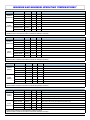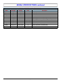
1
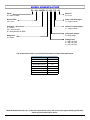
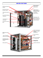
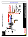
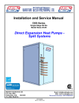
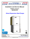
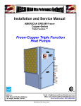
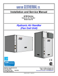
ENGINEERING SPECIFICATIONS W-100-HAC(W)-P-*S-CC Single-Stage R410a Nominal Size 9 Ton Reversing (Heating AND Cooling) Optional Domestic Hot Water (desuperheater) Commercial Hydronic Geothermal Heat Pumps Maritime Geothermal Ltd. PO Box 2555 Petitcodiac, NB E4Z 6H4 Ph. (506) 756-8135 [email protected] www.nordicghp.com Document Number: 001729SPC-02 ECO 000226 REVISION DATE: 15 NOV 2014 MODEL NOMENCLATURE W—100—HACW—P—2S—CC—03 Series: W = water to water Revision: 01, 02 etc. Nominal Size: 100 = 9 ton Indoor Loop Exchanger: C = copper coaxial Functions: H = heating AC = active cooling W = desuperheater for DHW Outdoor Loop Exchanger: C = copper coaxial Compressor Stages: S = single stage Refrigerant: P = R410a Voltage Code: 2 = 208-3-60 VAC 4 = 460-3-60 VAC 5 = 575-3-60 VAC The models and revisions covered by this document are listed in the table below. MODEL REVISION W-100-HAC-P-2S-CC 03 W-100-HAC-P-4S-CC 03 W-100-HAC-P-5S-CC 03 W-100-HACW-P-2S-CC 03 W-100-HACW-P-4S-CC 03 W-100-HACW-P-5S-CC 03 Maritime Geothermal Ltd. has a continuous improvement policy and reserves the right to modify specification data at any time without prior notice . 15 NOV 2014 Page 2 001729SPC-02 DESIGN FEATURES LIST The geothermal heat pump described in this specification document features the following: ETL listed for electrical certification 20ga satin galvanized case with reinforcing channel stiffeners Baked enamel finish Acoustically insulated cabinet (1/2” thick) Completely insulated heat exchangers and piping Four removable access panels Refrigeration service ports located inside unit (1/4” Schrader) 1-1/4” brass FPT fittings for Outdoor and Indoor Loop connections Single scroll compressor with sump heater Suction line and discharge line vibration absorbers Suction line accumulator Liquid line filter-drier Liquid line sight glass Electronic Expansion Valve (EEV) Reversing, can be used for heating and cooling High and low pressure sensors Phase protector High and low pressure sensors Suction line temperature sensor Manual reset high pressure control (each circuit) ECM circulator for domestic hot water circuit uses less than half the power of traditional circulating pumps, and allows motor replacement without tools (HACW only) 1/2” brass FPT fittings, double wall heat exchanger and high temperature cutout switch for domestic hot water (HACW only) Advanced control board with BACNet interface for remote operation and data access including all sensor data and alarm conditions, PWM outputs (or 0-10VDC), configurable analog inputs (0-10VDC or 420mA) with on board 5VDC, 12VDC or 24VDC power supplies. USB port for complete data access including real-time charting, data-logging and diagnostic functionality with manual override operation 2 x 16 LCD display for control and data access , unit may be configured for stand alone operation (requires optional temperature probes(s) Random start on power up (between 0-2 minutes) Dry contacts for external pump control (24VAC 5A MAX) Electrical box layout and schematic diagrams Installation and service manual OPTIONAL EQUIPMENT The following is a list of optional equipment that may be ordered with the geothermal heat pump: Temperature probes(s) for stand alone operation configuration 1-1/4” solenoid water valve (24VAC) 15 NOV 2014 Page 3 001729SPC-02 DESIGN FEATURES ECM domestic hot water circulator (HACW only) Refrigerant pressure sensors Manual reset high pressure control Heavy duty 1/2” brass FPT ports for domestic hot water connections (HACW ONLY) Swing-out electrical box Suction & Discharge Vibrasorbs Heavy duty 1-1/4” brass FPT ports for Indoor and Outdoor loop connections Copeland Scroll compressor Suction line accumulator Double wall desuperheater for domestic hot water (HACW only) Refrigerant access ports 4-way reversing valve 16x2 LCD display and button interface EEV with sight glass for cooling mode Advanced control board with BACnet interface Sight glass for heating mode Phase protector 15 NOV 2014 Liquid line filter-drier Page 4 001729SPC-02 CASE DETAILS Front View Right Side View Left Side View 15 NOV 2014 Page 5 001729SPC-02 ELECTRICAL BOX LAYOUT 460-3-60 and 575-3-60 Legend 13. 14. 15. 16. 17. 18. 19. 20. 21. 24. 25. 26. 28. 29. 30. Compressor contactor Circulator Control Relay Control transformer DHW circulator transformer (HACW only) Circulator Control terminal strip Ground lug Fuse holders Control Transformer Primary Fuse DHW Primary Fuses (HACW only) DHW Secondary Fuse (HACW only) Control Transformer Secondary Fuse Fuse Holders Control board 16x2 LCD display Menu buttons ELECTRICAL BOX LAYOUT 208-3-60 Legend 13. 14. 15. 16. 17. 18. 21. 22. 23. 15 NOV 2014 Page 6 Compressor contactor Circulator Control Relay Control transformer Circulator Control terminal strip Ground lug Phase monitor Control board 16x2 LCD display Menu buttons 001729SPC-02 ELECTRICAL SPECIFICATIONS Heat Pump Electrical Information Nomenclature Identifier Power Supply V-ø-Hz 208-3-60 460-3-60 575-3-60 2 4 5 MIN 187 414 518 MAX 229 506 632 Compressor #1 RLA LRA 33.6 225 18.6 114 13.6 80 FLA MCA Amps 34.1 19.1 14.4 Amps 42.5 23.8 17.8 Maximum Fuse/Breaker Amps 70 40 30 Minimum Wire Size ga #6-4 #8-3 #10-3 MISCELLANEOUS INFORMATION Unit Weight Lbs. kg Refrigerant Type Refrigerant Charge Lbs. 670 304 R410a 16.0 NOTE: Pressure drops are for water at 28USGPM (1.74L/s) 15 NOV 2014 Outdoor Pressure Drop Indoor Pressure Drop kg ELT PSI (kPa) EWT PSI (kPa) 7.3 50F(10C) 5.7 (39.3) 80F (27C) 4.1 (28.3) Page 7 001729SPC-02 ELECTRICAL DIAGRAMS 15 NOV 2014 Page 8 001729SPC-02 ELECTRICAL DIAGRAMS (continued) 15 NOV 2014 Page 9 001729SPC-02 ELECTRICAL DIAGRAMS (continued) 15 NOV 2014 Page 10 001729SPC-02 REFRIGERATION CIRCUIT DIAGRAMS—HAC & HACW 15 NOV 2014 Page 11 001729SPC-02 REFRIGERATION CIRCUIT DIAGRAMS—HAC & HACW (continued) 15 NOV 2014 Page 12 001729SPC-02 CAPACITY RATINGS Heating W-100-HAC(W) Source Data (Outdoor Loop) ELT Evap. Temp Flow LLT Delta T HAB BTU/Hr °F °F USGPM °F °F °C °C L/s °C °C 27.0 15 28.0 22.3 4.7 -2.8 -9.4 1.74 -5.4 2.6 33.0 20 28.0 27.8 5.2 0.6 -6.7 1.74 -2.3 2.9 39.0 25 28.0 33.2 5.8 3.9 -3.9 1.74 0.7 3.2 45.0 30 28.0 38.6 6.4 7.2 -1.1 1.74 3.7 3.6 50.0 35 28.0 42.9 7.1 11.1 1.7 1.74 6.1 3.9 56.0 40 28.0 48.2 7.8 14.4 4.4 1.74 9.0 4.3 62.0 45 28.0 53.4 8.6 17.8 7.2 1.74 11.9 4.8 68.0 50 28.0 58.6 9.4 21.1 10.0 1.74 14.8 5.2 64,291 71,729 Nominal 9 Ton Power Consumption Total Watts COPh Amps* 7381 W/W 9.2 7393 3.55 9.2 3.84 R410a 60 Hz Sink Data (Indoor Loop) EWT Cond. Temp. Flow LWT Delta T Output °F °F USGPM °F °F °C °C L/s °C °C 95.0 110 28.0 101.5 6.5 35.0 43.3 1.74 38.6 3.6 95.0 110 28.0 102.0 7.0 35.0 43.3 1.74 38.9 3.9 102.6 7.6 79,727 7401 9.2 4.16 95.0 110 28.0 35.0 43.3 1.74 39.2 4.2 88,322 7409 9.2 4.49 95.0 110 28.0 103.2 8.2 35.0 43.3 1.74 39.6 4.6 97,555 107,463 7419 9.3 7434 4.85 9.3 5.24 95.0 110 28.0 103.9 8.9 35.0 43.3 1.74 39.9 4.9 95.0 110 28.0 104.6 9.6 35.0 43.3 1.74 40.3 5.3 105.4 10.4 118,085 7458 9.3 5.64 95.0 110 28.0 35.0 43.3 1.74 40.8 5.8 129,461 7493 9.3 6.06 95.0 110 28.0 106.2 11.2 35.0 43.3 1.74 41.2 6.2 * Amps for 575VAC; multiply by 2.8 for 208VAC, by 1.25 for 460VAC BTU/Hr 89,483 96,960 104,985 113,608 122,875 132,836 143,539 155,033 Compressor: ZP103KCE-TFE (575-3-60) Cooling W-100-HAC(W) Source Data (Indoor Loop) Power Consumption ELT Evap. Temp Flow LLT Delta T HAB °F °F USGPM °F °F BTU/Hr Watts 127,052 5302 °C °C L/s °C °C 52.0 40 28.0 42.8 9.2 11.1 4.4 1.74 6.0 5.1 52.0 40 28.0 43.0 9.0 11.1 4.4 1.74 6.1 5.0 52.0 40 28.0 43.3 8.8 11.1 4.4 1.74 6.3 4.9 52.0 40 28.0 43.5 8.5 11.1 4.4 1.74 6.4 4.7 52.0 40 28.0 43.7 8.3 11.1 4.4 1.74 6.5 4.6 52.0 40 28.0 44.0 8.0 11.1 4.4 1.74 6.6 4.5 52.0 40 28.0 44.2 7.8 11.1 4.4 1.74 6.8 4.3 52.0 40 28.0 44.7 7.3 11.1 4.4 1.74 7.1 4.0 123,911 Efficiency ELT Cond. Temp. Flow LLT Amps* EER °F °F USGPM °F °C °C L/s °C °C 7.4 24.0 65.0 80 28.0 75.5 10.5 18.3 26.7 1.74 24.2 5.8 Total 5609 7.7 22.1 Delta T Rejection °F 70.0 85 28.0 80.4 10.4 21.1 29.4 1.74 26.9 5.8 85.2 10.2 120,732 5932 8.0 20.4 75.0 90 28.0 23.9 32.2 1.74 29.6 5.7 117,507 6273 8.2 18.7 80.0 95 28.0 90.1 10.1 26.7 35.0 1.74 32.3 5.6 114,226 6636 8.6 17.2 85.0 100 28.0 94.9 9.9 29.4 37.8 1.74 35.0 5.5 99.8 9.8 110,881 7022 8.9 15.8 90.0 105 28.0 32.2 40.6 1.74 37.7 5.5 107,463 7434 9.3 14.5 95.0 110 28.0 104.6 9.6 35.0 43.3 1.74 40.3 5.3 100,370 8349 10.1 * Amps for 575VAC; multiply by 2.8 for 208VAC, by 1.25 for 460VAC 15 NOV 2014 R410a 60 Hz Sink Data (Outdoor Loop) 12.0 105 120 28.0 114.3 9.3 40.6 48.9 1.74 45.7 5.2 BTU/Hr 145,147 143,054 140,978 138,918 136,874 134,847 132,836 128,864 Compressor: ZP103KCE-TFE (575-3-60) Page 13 001729SPC-02 MINIMUM AND MAXIMUM OPERATING TEMPERATURES* Loop Parameter Mode (°F) (°C) Minimum ELT Outdoor Maximum ELT (Antifreeze) Minimum ELT Heating 26 -3 Heating 80 27 Cooling 41 5 Maximum ELT Cooling 113 45 Minimum EWT Heating 43** 6** Maximum EWT Indoor (Antifreeze) Minimum EWT Heating 120 49 Cooling 41 5 Maximum EWT Cooling 80 27 Notes Flow control valve may be required in Outdoor Loop. Flow control valve may be required in Indoor Loop. * Values in this table are for rated liquid and water flow values. ** Reduce Indoor Loop flow until value is reached for startup if necessary. Loop Mode (°F) (°C) Minimum ELT Heating 26 -3 Outdoor Maximum ELT (Antifreeze) Minimum ELT Heating 80 27 Cooling 46 8 Maximum ELT Cooling 113 45 Minimum EWT Heating 50** 10** Maximum EWT Heating 120 49 Minimum EWT Cooling 45 7 Maximum EWT Cooling 80 27 Indoor (Water) Parameter Notes Flow control valve may be required in Outdoor Loop. Flow control valve may be required in Indoor Loop. * Values in this table are for rated liquid and water flow values. ** Reduce Indoor Loop flow until value is reached for startup if necessary. Loop Outdoor (Water) Indoor (Water) Parameter Mode (°F) (°C) Minimum ELT Heating 43 6 Maximum ELT Heating 80 27 Minimum ELT Cooling 46 8 Maximum ELT Cooling 113 45 Minimum EWT Heating 50** 10** Maximum EWT Heating 120 49 Minimum EWT Cooling 45 7 Maximum EWT Cooling 80 27 Notes Flow control valve may be required in Outdoor Loop. Flow control valve may be required in Indoor Loop. * Values in this table are for rated liquid and water flow values. ** Reduce Indoor Loop flow until value is reached for startup if necessary. Loop Mode (°F) Minimum ELT Heating 43 6 Maximum ELT Heating 80 27 Minimum ELT Cooling 46 8 Maximum ELT Cooling 113 45 Minimum EWT Heating 43** 6** Maximum EWT Indoor (Antifreeze) Minimum EWT Heating 120 49 Cooling 41 5 Maximum EWT Cooling 80 27 Outdoor (Water) Parameter (°C) Notes Flow control valve may be required in Outdoor Loop. Flow control valve may be required in Indoor Loop. * Values in this table are for rated liquid and water flow values. ** Reduce Indoor Loop flow until value is reached for startup if necessary. 15 NOV 2014 Page 14 001729SPC-02 BACNet SPECIFICATIONS The BACNet interface is an MS/TP connection via RS-485 twisted pair. The connector on the control board is a three wire removable screw connector. The signals are as follows: A: Communications line (+) B: Communications line (-) C: Ground connection The following tables provide a list of the available objects along with a description of each. BACNet OBJECTS - CONTROL (READ/WRITE) Name Data Type Property Units TSTAT_Y1A Binary Input Present Value - Description Control signal to start / stop stage 1 (active is on) Control Signal to switch between heating and cooling mode TSTAT_O Binary Input Present Value (active in cooling mode) Note: object names may be subject to change without prior notice. BACNet OBJECTS - ALARMS (READ ONLY) Name Data Type Property Units LPS1 HPS1 PM1 PERM1 Analog Input Analog Input Analog Input Analog Input Alarm Alarm Alarm Alarm - ODFLO Analog Input Alarm IDFLO Analog Input Alarm Note: objects may be subject to change without prior notice. 15 NOV 2014 Description Stage 1 low pressure alarm (suction pressure) Stage 1 high pressure alarm (discharge pressure) Stage 1 phase monitor alarm Stage 1 permanent lockout alarm Outdoor loop flow alarm Indoor loop flow alarm Page 15 001729SPC-02 BACNet SPECIFICATIONS continued BACNet OBJECTS - DATA (READ ONLY) Name Data Type Property Units HP_MODEL HP_SERIAL FIRM_REV Analog Value Analog Value Analog Value Description Description Description - LPS1 HPS1 TS1 SH_TS1 EEV1_POS AMPS1 Analog Input Analog Input Analog Value Analog Value Analog Output Analog Input Present Value Present Value Present Value Present Value Present Value Present Value PSIG (kPa) PSIG (kPa) degF (degC) degF (degC) % A Description Heat pump model, ie “W-100-H-P-5S-PP-01” Heat pump serial number ie “6500-01-13” Firmware revision ie “Firmware REV 01 Stage 2 low pressure value (suction pressure) Stage 2 high pressure value (discharge pressure) Stage 2 suction line temperature Stage 2 superheat Stage 2 EEV position (% open) Stage 2 compressor current draw (AI0) Note: objects may be subject to change without prior notice. 15 NOV 2014 Page 16 001729SPC-02 ENGINEERING GUIDE SPECIFICATIONS General The liquid source reversing water-to-water heat pump shall be a single packaged reverse-cycle heating/cooling unit, with desuperheating circuit for domestic hot water production (HACW only). The unit shall be listed by a nationally recognized safety-testing laboratory or agency, such as ETL Testing Laboratory, Underwriters Laboratory (UL), or Canadian Standards Association (CSA). The unit shall be rated in accordance with applicable standards of the Air Conditioning, Heating, and Refrigeration Institute / International Standards Organization (AHRI/ISO) and/or Canadian Standards Association (CSA). The liquid source water to water heat pump unit, as manufactured by Maritime Geothermal, Petitcodiac, New Brunswick, shall be designed to operate correctly within liquid temperature ranges specified on the “Minimum and Maximum Operating Temperatures” page of this engineering specification document. Factory Quality Each unit shall be run tested at the factory with water circulating in both indoor and outdoor loops. Quality control system checks shall include: computerized nitrogen pressurized leak test, evacuation of refrigeration circuit to sustained vacuum, accurate system charge, detailed heating and cooling mode tests, and quality cross check all operational and test conditions to pass/fail criteria. Units tested without water flow are not acceptable. The units shall be warranted by the manufacturer against defects in materials and workmanship for a period of one (1) year from startup or one year plus 60 days from shipment. Optional extended factory warranty coverage shall be available. Cabinet Each unit shall be enclosed in a sheet metal cabinet. Cabinet shall be constructed of painted galvanized sheet metal of minimum 20 gauge. Sheet metal gauge shall be higher where structurally required. Design and construction of cabinet shall be such that it is rigid and passes the CSA/UL Loading Test requirements (200 lb roof test and 25 lb guard test). All panels shall be lined with minimum 1/2 inch [12.7 mm] thick acoustic type glass fiber insulation. All insulation shall meet the fire retardant provisions of NFPA 90A. This material shall also provide acoustical benefit. The unit must have a minimum of three access panels for serviceability of the compressor compartment. Units having only one access panel to compressor/heat exchangers/expansion device/refrigerant piping shall not be acceptable. The electrical box shall have separate holes and knockouts for entrance of line voltage and low voltage control wiring. All factory-installed wiring passing through factory knockouts and openings shall be protected from sheet metal edges at openings by plastic grommets. Refrigerant Circuit All units shall contain only one sealed refrigerant circuit, containing a hermetic motor scroll compressor, bidirectional electronic expansion valve, reversing valve, coaxial heat exchangers, factory installed high and low pressure safety switches, service ports, liquid line filter dryer, sight glass, desuperheating heat exchanger (HACW only), and suction accumulator. Compressor shall be specified for heat pump duty with internal isolation consisting of rubber vibration isolators. Compressor motor shall have internal overload protection. Compressor shall be mechanically isolated from rest of refrigerant circuit by suction and discharge vibration absorbers. Piping shall be protected from resonant vibration through use of a discharge muffler specifically designed to reduce gas pulsations or equivalent. Compressor shall be equipped with a crankcase/sump heater to prevent liquid refrigerant migration during the off cycle and subsequent flooded starts. The water to refrigerant heat exchangers shall consist of a steel outer jacket with twisted copper inner tube, designed and certified for 600 psig [4136 kPa] working pressure on the refrigerant side and 450 psig [3108 kPa] on the water side. Heat exchangers headered together in parallel shall use a reverse-return or symmetrical arrangement on the water side and symmetrical arrangement on the refrigerant side to ensure even flow splitting. Heat exchangers shall be insulated over all of their outside surface with minimum 3/8” thick closed cell insulation. Insulation consisting of 1/8” closed-cell insulating tape shall not be acceptable. The electronic expansion valve shall be of stepper-motor rather than pulsing type, and shall provide proper superheat control over the unit’s operating range with minimal deviation from superheat setpoint. The valve shall operate bidirectionally without the use of check valves. The valve shall be controlled by an electronic superheat controller which provides operator-adjustable superheat and real-time LED/LCD display of current superheat. Superheat shall be determined through the suction pressure-temperature method. Externally mounted pressure controlled water regulating flow valves or thermostatic expansion valve (TXV) in place of an electronic expansion valve are not acceptable. 15 NOV 2014 Page 17 001729SPC-02 ENGINEERING GUIDE SPECIFICATIONS (continued) The following paragraph applies only to HACW models only. The desuperheating circuit for domestic hot water production shall consist of a double-wall refrigerant to water heat exchanger, designed so that any escaped refrigerant will enter the ambient air and not the domestic hot water circuit. Heat exchanger shall be designed for minimal refrigerant pressure drop, and shall not be oversized in order to maintain primary heating output when heating domestic hot water from the temperature of its cold water source. Domestic hot water circuit shall include a circulating pump wired so that it does not require additional controls. Domestic hot water circuit shall include a temperature switch to turn off domestic hot water production when the domestic water out temperature exceeds 140 degrees Fahrenheit. The suction accumulator shall be insulated with minimum 3/8” thick closed cell insulation to prevent condensation. The accumulator’s internal oil return port shall be sized properly for the unit’s operating range. To ensure proper oil return, suction accumulator shall not be ‘oversized’. Piping and Connections The unit shall have one set of primary water in and water out connections. The primary connection type shall be 1-1/4” nominal female National Pipe Thread (NPT). Domestic hot water (desuperheater) water connectors shall be ½” nominal female National Pipe Thread (NPT) (HACW only) All water connectors shall be rigidly mounted to cabinet with corrosion resistant fasteners to prevent relative movement. All water connectors shall be constructed of copper or brass material for corrosion resistance. All internal water and refrigerant piping shall be insulated with minimum 3/8” thick closed cell insulation. Insulation consisting of 1/8” closed-cell insulating tape shall not be acceptable. Electrical Controls and safety devices shall be factory wired and mounted within the unit. Controls shall include 24 volt alternating current (24VAC) activated compressor contactors, 24VAC 100VA transformer with built in circuit breaker or fused on both primary and secondary sides, and 24VAC reversing valve coil. A terminal strip with screw in terminals shall be provided for field control wiring. Units shall be name-plated for use with time delay fuses or circuit breakers. Unit controls shall be 24VAC and provide heating or cooling as required by the remote thermostat or controller. 3-phase protection shall be present in each unit to protect the compressor against loss of phase and reverse rotation. 3-phase protection shall be factory installed. Unit shall have dry contacts for controlling loop circulating pumps via an external 24VAC contactor. Unit shall provide remote fault indication to the thermostat via a 24VAC trouble signal. Unit Control The control system shall have the following features: 1. Anti-short cycle time delay on compressor operation. Time delay shall be a minimum of 5 minutes, for both thermostat demand and safety control reset starts. A test jumper shall be provided to disable this delay for unit commissioning and testing purposes. 2. Random compressor start delay of 0-120 seconds (in addition to 5 minute anti-short cycle timer) on unit power up to facilitate starting multiple units on one disconnect switch or after a power failure. 3. Compressor shutdown for high or low refrigerant pressures. 4. Automatic intelligent reset: unit shall automatically restart 5 minutes after trip if the fault has cleared. Should a fault reoccur 3 times sequentially then permanent lockout shall occur, requiring cycling of the power to the unit in order to reset. 5. Manual reset high pressure in case of electronic board failure. The low pressure shall not be monitored for the first 90 seconds after a compressor start to prevent nuisance safety trips. Maritime Geothermal works continually to improve its products. As a result, the design and specifications of any product may be changed without notice. Please contact Maritime Geothermal at 1-506-756-8135 or visit www.nordicghp.com for latest design and specifications. Purchaser’s approval of this data set signifies that the equipment is acceptable under the provisions of the job specification. Statements and other information contained herein are not express warranties and do not form the basis of any commercial contract or other agreement between any parties, but are merely Maritime Geothermal’s statement of opinion regarding its products. 15 NOV 2014 Page 18 001729SPC-02 LIMITED WARRANTY MARITIME GEOTHERMAL LTD. warrants that its commercial geothermal heat pumps shall be free from defects in materials and workmanship for a period of ONE (1) YEAR after the date of installation or for a period of ONE (1) YEAR AND SIXTY (60) DAYS after the date of shipment, whichever occurs first. This warranty covers all internal components of the heat pump. MARITIME GEOTHERMAL LTD. shall, at its option, repair or replace any part covered by this warranty. Defective parts shall be returned to MARITIME GEOTHERMAL LTD., transportation charges prepaid. Replacement or repaired parts and components are warranted only for the remaining portion of the original warranty period. This warranty is subject to the following conditions: 1. The geothermal heat pump must be properly installed and maintained in accordance with MARITIME GEOTHERMAL LTD. guidelines. 2. The installer must complete the Startup Record and return it to MARITIME GEOTHERMAL LTD. within 21 days of unit installation. 3. For new construction, it is the responsibility of the building or general contractor to supply temporary heat to the structure prior to occupancy. Geothermal heat pumps are designed to provide heat only to the completely finished and insulated structure. Startup of the unit shall not be scheduled prior to completion of construction and final duct installation for validation of this warranty. 4. It is the customer's responsibility to supply the proper quantity and quality of water or properly sized ground loop with adequate freeze protection. If a geothermal heat pump manufactured by MARITIME GEOTHERMAL LTD. fails to conform to this warranty, MARITIME GEOTHERMAL LTD.'s sole and exclusive liability shall be, at its option, to repair or replace any part or component which is returned by the customer during the applicable warranty period set forth above, provided that (1) MARITIME GEOTHERMAL LTD. is promptly notified in writing upon discovery by the customer that such part or component fails to conform to this warranty; (2) the customer returns such part or component to MARITIME GEOTHERMAL LTD., transportation charges prepaid, within (30) thirty days of failure, and (3) MARITIME GEOTHERMAL LTD.'s examination of such component discloses to its satisfaction that such part or component fails to conform to this warranty and the alleged defects were not caused by accident, misuse, neglect, alteration, improper installation, repair or improper testing. MARITIME GEOTHERMAL LTD. will not be responsible for any consequential damages or labour costs incurred. In additional, MARITIME GEOTHERMAL LTD. will not be responsible for the cost of replacement parts purchased from a third party. 15 NOV 2014 Page 19 001729SPC-02