1
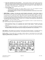
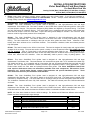
INSTALLATION INSTRUCTIONS
Victor Small-Block Ford Race Heads
For Small Block Ford V8s
Catalog # 61099 (Bare), #61299 (Bare), #77099 (Bare Castings),
#77219 (Bare), #77289 (Bare), #77299 (Bare)
§
Please study these instructions carefully before installing your new cylinder heads. If you have any questions or
problems, please call our Technical Hotline at: 1-800-416-8628, 7:00 am – 5:00 pm, Pacific Standard Time, Monday
through Friday or e-mail us at [email protected].
DESCRIPTION: These heads require professional head preparation.
#61099 - This Victor Small-Block Ford cylinder head is designed for ultra high-performance 302 and larger
displacement Ford Windsor V8s. This head is based on the #77099 Victor cylinder head along with the valve guide
and seat location changes. The ports were designed by Billy Glidden and digitized by Chapman Racing. The heads
are fully CNC-ported by Chapman Racing. The valve seats have a multi-angle valve job and the valve guides have
been honed to accept a .3410” dia. valve stem. Proper valve sizing should always be checked. Out of the box, these
heads on a 360-ci engine have produced 750+ Horsepower.
#61299 - This Victor Small-Block Ford cylinder head is designed for ultra high-performance 302 and larger
displacement ford Windsor V8s. This head is based on the #77219 Victor head. It is fully CNC-ported by Chapman
Racing. The valve seats have a multi-angle valve job and the valve guides have been honed. tI features a .060”
thicker deck, which achieves a 61cc combustion chamber. The combustion chambers, intake and exhaust ports are
fully CNC-ported.
#77099 - This head is based on the #77219 Victor head. This head is designed for head porters and engine builders
engaged in all out racing. The ports are small to permit a variety or runner shapes and sizes. The guides and seats
are not installed. There is a great deal or work required preparing these heads for use. The heads have a 15degree valve angle, exhaust guides have been moved .060” away from bore centerline and the intake guide has been
moved .095” toward the bore centerline. Ports are deliberately small to permit a verity of porting options. The
#77219 - This Victor Small-Block Ford cylinder head is designed for ultra high-performance 302 and larger
displacement Ford Windsor V8s. This head features .52” raised exhaust ports and a .375” extended and raised high
flow intake port flange. It is compatible with all Victor-series 302 and 351-based manifolds when used with end seal
spacers. The 47cc (as-cast) combustion chamber promotes high compression ratios in racing applications. These
heads include ductile iron valve seats and phosphor-bronze valve guides. The Victor Small-Block Ford #77219
head requires shaft-mount rocker arm assemblies (available from Jesel components, T&D machine, Probe
Industries, etc.), special header flanges, custom length pushrods and special aftermarket pistons. These
bare heads have not been port-matched or bowl-blended.
#77289 - This Victor Small-Block Ford cylinder head is designed for ultra high-performance 302 and larger
displacement ford Windsor V8s. This head is based on the #77219 Victor head. The heads are then partially CNCmachined by Chapman Racing. The valve seats have a multi-angle valve job and the valve guides have been honed.
The combustion chambers have been fully CNC machined. The intake and exhaust ports have CNC-blended entries
and bowls.
#77299 - This Victor Small-Block Ford cylinder head is designed for ultra high-performance 302 and larger
displacement ford Windsor V8s. This head is based on the #77289 Victor head. With the benefits listed above, this
head also features a .060” thicker deck than the #77289 to achieve a combustion chamber volume of 61cc.
NOTE: All of the above heads are from the #77219 castings. The #61099 and #77099 have different valve locations.
Please read above text to prevent engine damage.
Part No. Victor Ford Cylinder Heads
Chamber Size
61099
Fully CNC Ported Bare cylinder heads
60cc
61299
Fully CNC Ported Bare cylinder heads
61cc
77099
Bare Raw Casting
**cc
77219
Bare As Cast
47cc
77289
Partially CNC Ported Bare cylinder heads
48cc
77299
Partially CNC Ported Bare cylinder heads
61cc
©2002 Edelbrock Corporation
Brochure No. 63-0017
Page 1 of 5
Rev. 01/02
§
ACCESSORIES:
below.
We highly recommend that premium quality hardware be used with your new heads, as listed
Head Bolts or Studs: High quality head studs or head bolts with hardened washers must be used to prevent galling
of the aluminum bolt bosses. Recommended head bolts are ARP #254-3708 for engines with 7/16" head bolt holes
(289 and 302). You may use Edelbrock Head Bolt Kit #8552 or high quality 7/16" bolts or studs on 289-302 engines
only if you purchase Edelbrock head bolt bushings with integral washers #9680. Engines with 1/2" diameter head
bolts (351-W and 302 SVO) use Edelbrock Head Bolt Kit #8553 or stock 351-W bolts with high quality head bolt
washers such as ARP #200-8533. For torque sequence, see Figure #1.
NOTE:
It is recommended that 289-302 engines producing 380 or more horsepower (or with nitrous oxide) be
converted to accept 1/2" diameter head bolts by a qualified machine shop to ensure maximum head gasket
durability.
Pistons: Because of the unique combustion chamber shape, special pistons are required. Pistons with the proper
dome shape are available from JE Pistons. These are not off-the-shelf pistons, as variables such as bore, stroke, and
rod length may be different for each application.
Rocker Arms:
Aftermarket shaft rockers are required. The parts used in testing are available from Jesel
Components (#KRA14371), T&D Machine (#7350), or Probe Industries (#PSR-2894, 1.6:1 or #PSR-2895, 1.7:1). The
#6109 and #7709 have off set valves and require custom rocker assemblies. Contact above listed manufacturers.
Pushrod Length: Custom length 5/16" diameter pushrods will be required. The length will vary depending on your
valve length and camshaft/lifter combination. Follow the rocker arm manufacturer’s instruction for determining the
correct pushrod length for your application.
Valve Covers: Standard Ford valve covers will fit. We recommend Edelbrock Signature Series chrome valve covers
#4460 or Elite Series polished aluminum valve covers #4260.
Intake Manifold: Edelbrock Race Cylinder Heads are matched in size and operating range with Edelbrock Victor and
Super Victor series intake manifolds. Additionally, any manifold that matches Fel-Pro gasket #1262 or equivalent may
be used. Intake manifolds must be port-matched to the cylinder heads for optimum performance. Because of the
extended intake flanges, the intake manifold will sit .50" higher than with stock heads. Edelbrock #7726 kit includes
.50” thick end seal spacers for both 302 or 351w based applications and is sold separately. Secure the
spacers to your block with screws or pin, and use RTV silicone sealer between the spacers and the block during
spacer to block installation. Due to the many applications, you may need to machine the end seal spacers for your
engine build.
Intake Manifold Bolts: The intake manifold bolts must be long enough to have engagement with the full length of the
Helicoil Thread insert. Over-torquing of the intake manifold bolts can create many problems, including thread failure
and intake or head gasket failure. You may want to use oil or ARP assembly lubricant on bolts.
Distributor to Intake Manifold Clearance: Because of the .50" higher position of the intake manifold on the engine
with these heads, the clearance of the distributor housing to the intake manifold water crossover may be
compromised. If enough clearance cannot be obtained with your distributor, taller housing distributors are available
from MSD (302 - P/N 8579, 351W - P/N 8578, 351C - P/N 8577).
Spark Plugs: Use 14mm x 3/4" reach gasketed spark plugs with a 5/8" hex (Champion C series or equivalent). Heat
range for competition applications will vary. Use anti-seize on the plug threads to prevent galling in the cylinder
head, and torque to 10 ft./lbs. Do not overtighten spark plugs!
Header Flange Plates #7722: Custom flange plates must be used with Victor small-block Ford cylinder heads
#77289/77299 due to the unique bolt pattern. The wide 2-1/2" bolt spacing allows ample room for even the largest
header tubes for competition applications. Edelbrock Header Flange plates #7722 are laser-cut from 3/8" mild steel.
§
IMPORTANT: CHECK BEFORE INSTALLATION
Before final installation of the cylinder heads, several things need to be checked to ensure proper engine operation:
1.
Piston to valve clearance – Minimum intake valve clearance should be .080”. Minimum exhaust valve clearance
should be .110”. The point of minimum intake valve to piston clearance will usually occur somewhere between 5
and 15º ATDC during valve overlap. The point of minimum exhaust valve to piston clearance will usually occur
15º to 5º BTDC during valve overlap. Re-machining of the piston top eyebrows may be required with some
pistons.
©2002 Edelbrock Corporation
Brochure No. 63-0017
Page 2 of 5
Rev. 01/02
§
2.
Proper lifter adjustment and rocker geometry –. Rocker geometry should be checked making sure that the
contact point of the roller remains properly on the valve tip and does not roll off the edge. Visual inspection of the
rockers, valve springs, retainers, and pushrods should be made to ensure that none of these components come
into improper contact with each other. If problems with valve train geometry occur, simple changes such as
pushrod length or rocker stand height may have to be made.
§
OTHER ASSEMBLY TIPS
ü When installing the sparkplugs and exhaust headers, be sure to use a high temperature anti-seize
compound on the threads to reduce the possibility of thread damage in the future.
ü Do not exceed a torque of 15 ft./lbs. on the intake manifold bolts and lubricate the bolt threads
prior to assembly.
INSTALLATION: Installation is the same as for original equipment cylinder heads. Consult service manual for
specific procedures, if necessary. See head gasket section for gasket recommendations. Be sure that the surface of
the block and the surface of the head are thoroughly cleaned to remove any oily film before installation. Use alcohol
or lacquer thinner on a lint-free rag to clean. Apply moly-oil mixture to head bolt threads, washer, and area under
head bolt to prevent galling and improper torque readings. Torque to 70 ft./lbs. for 7/16" bolts (289/302) or 100 ft./lbs.
for 1/2" bolts (351-W) in three or four steps following the factory tightening sequence (see Figure 1), then tighten the
long (upper) head bolts to 80 ft./lbs. (7/16") or 110 ft./lbs. (1/2"). A re-torque is recommended after initial start-up and
cool-down (allow 2-3 hours for adequate cooling).
HEAD GASKETS: Head gasket requirements change according the application for which the cylinder heads are being
used. Use the following as a guide for head gasket selection:
1.
2.
Medium performance engines, 10-12:1 compression ratio, increased preload cylinder head fasteners (7/16" stud
or 1/2" head bolts or studs), not recommended with nitrous or forced induction - Fel-Pro Head Gasket
P/N 1011-2.
Highest performance racing engines. 12:1 and above compression ratio, 1/2" cylinder head fasteners designed for
the highest preload, engines using nitrous or forced induction- Fel-Pro Head Gasket p/n 1006 Locwire.This gasket
will require modification of the head deck surface by a competent machine shop to Fel-Pro specifications.
Intake Gaskets: Intake gaskets will vary according to engine design and builder’s preference. The gasket used during
testing at Edelbrock is the Fel-Pro gasket Part #1262 R . End seal spacer kit #7726 is required and sold separately.
Exhaust gaskets: Exhaust gaskets will vary according to builder’s preference. Some builders will use Silicone sealer
designed for exhaust system. The method used at Edelbrock was 2 sets of Fel-Pro Part #1482. Use only the outboard
single port gaskets from the Fel-Pro #1482 kits.
©2002 Edelbrock Corporation
Brochure No. 63-0017
Page 3 of 5
Rev. 01/02
§
SPECIFICATIONS:
Head Bolt Torque:
Intake Bolt Torque:
Combustion Chamber Volume:
#61099………………………………
#61299………………………………
#77099………………………………
#77219………………………………
#77289………………………………
#77299………………………………
Intake Runner Volume:
#61099………………………………
#61299………………………………
#77099………………………………
#77219………………………………
#77289………………………………
#77299………………………………
Exhaust Runner Volume:
#61099………………………………
#61299………………………………
#77099………………………………
#77219………………………………
#77289………………………………
#77299………………………………
Deck Thickness:
Valve Seats:
Recommended Valve Size:
#61099………………………………
#61299………………………………
#77099………………………………
#77219………………………………
#77289………………………………
#77299………………………………
Valve Guide Inside Diameter:
Recommended Valve Lengths:
Valve Spring Diameter:
Pushrods:
Spark Plugs:
7/16 Bolts – 70/80ft-lbs.
(Short/Long Bolts) (In 3 steps)
1/2 Bolts- 100/110 ft-lbs
16-18 ft./lbs.
60cc CNC
61cc CNC
** cc As cast
47cc As-cast
48cc CNC
61cc CNC
274cc CNC
277cc CNC
** cc As cast
240cc As cast
240cc Partially CNC
240cc Partially CNC
87cc CNC
90cc CNC
** cc As cast
80cc As cast
90cc Partially CNC
90cc Partially CNC
5/8”
Hardened, interlocking, compatible with all types of fuel
Intake
Exhaust
Valve Center to Center
2.150”
1.560”
1.900”
2.125”
1.625”
1.935”
**
**
1.900”
2.125”
1.625”
1.935”
2.100”
1.650”
1.935”
2.100”
1.650”
1.935”
.342” I.D. Nominal
Similar to 18 Deg Chevrolet (Typically 5.450”-5.500” )
1.630”
5/16” dia. Hardened pushrods required for use
guideplates
14mm x ¾” reach gasketed seat
with
Note: Above asterisk (**) indicate unknown values. Size will vary according to the builder’s design.
Page 4 of 5
Brochure No. 63-0017
Rev. 01/02
§
SPECIAL INSTRUCTIONS FOR 351-C ENGINES
Installation of these Victor cylinder heads on a 351C block requires a thorough knowledge of 302-351W and 351-C
water cooling systems and their differences. The Ford SVO catalog has a good section on small block Ford water
jacket passages. The ability to perform custom machining and fabrication will be required to properly perform this
installation.
The Victor Small-Block Ford Race heads require an 11/16" diameter hole to be drilled through the head deck in the
position shown in Figure #2. The hole in the cylinder head deck only needs to be drilled in one end of the head, the
end of the head corresponding to the hole in the block deck for the cylinder bank that the head will be attached. If you
do not know whether the head will be mounted on the left or right cylinder bank, drill the head deck on both ends.
Bolthole break thru will occur as seen in Figure #2 and will require sealing of passage.
The engine block deck needs to be checked for water holes that may be adjacent to the cylinder head tooling point
recesses shown in Figure #2. These holes in the block deck will need to be plugged.
To make sure that air pockets do not form in the heads when filling the cooling system with coolant, we recommend
installation of a small steam bleed hose from the normal Windsor water outlet position on the intake face of each head
(through the intake manifold flange) to the water outlet housing on the block. This will allow air and steam that is
difficult to get out of a 351 Cleveland engine to be bled from the heads.
An intake manifold designed for Windsor heads on a 9.200" deck height block must be used. We recommend
Edelbrock intake manifolds Victor Jr. P/N 2980 and Super Victor P/N 2929. The front water crossover and
thermostat-housing flange will need to be removed and the resulting holes in the intake manifold flanges closed off.
The end seal areas will also need to be modified to match up with the 351-C end seals. End seal spacers, (.50"
thick), will also need to be fabricated.
Head Gaskets: Head gaskets designed for 351-C applications should be used. We suggest Fel-Pro #1022 or #1023
for most applications. If desired, the heads may be machined for Fel-Pro Locwire head gaskets #1006 following the
directions supplied with those gaskets.
On 351C and some SVO 351W blocks, two of the steam holes on the exhaust side of deck coincide with the Victor
head tooling point relief pockets shown on the following illustration. In order to avoid coolant leaks, these two holes
must be plugged up.
Fig. # 2
Note: Bolt hole break thru will occur as seen in Figure #2 and will require sealing of passage.
§
PLEASE complete and mail your warranty card. Be sure to write the model number of this product in the
“Part #________” space. THANK YOU.
Edelbrock Corporation • 2700 California Street • Torrance • California 90503
©2002 Edelbrock Corporation
Brochure No. 63-0017
Page 5 of 5
Rev. 01/02