1
800 XL™
COMPUTER
FIELD SERVICE
MANUAL
FD100740
ATARI
\
(u.s.)
CORP.
REV. 02
JUNE 1985
A T A RI
8 0 OXLTM
FIELD
COM PUT E R
SERVICE
MANUAL
Atari believes that the information descr ibed in this manual is accurate and reliable,
and much care has been taken in its preparation.
However, no responsibility,
financial
or otherwise,
shall be accepted
for any consequences
arising out of the use of this
material.
Information contained herein is subject to change. Revisions may be issued
to advise of such changes and! or additions.
Correspondence
regarding this document should be forwarded
Support, Consumer Product
Service,
Atari, Incorporated,
Sunnyvale, California
94-086.
to Director of Technical
1272 Borregas Avenue,
TABLE OF CONTENTS
Section
Title
Page
INTRODUCTION
v
THEOR Y OF OPERATION
1-1
User Interface
Mechanical Theory
Electrical Theory
6502C CPU Microprocessor
Alphanumeric
Television
Interface Controller
(ANTIC)
Graphic Television
Interface Adaptor (GTIA)
Pot Keyboard Integrated
Circuli:
(POKEY)
Peripheral Interface
Adaptor (PIA)
Memory (ROMs and DRAMs)
OS ROM
BASIC ROM
DRAMS
Memory Management
Unit (MMU)
RF Modulator
Monitor Output
Power Supply
System Interface
Serial Input/Output
(510) Interface
Keyboard Interface
Controller
Jack Interfaces
Cartridge Interface
Parallel Bus Interface
1-1
1-2
1-41-41-5
1-6
1-7
1-8
1-9
1-9
1-9
1-9
1-9
1-10
1-10
t-l0
1-11
1-11
1-12
1-13
1-13
1-15
TESTING
2-1
Overview
Equipment Needed
Self Test Features
Description
of Self Tests
Mernor y Test
Audio Visual Test
Keyboard Test
All Tests
SuperSAL T Testing
2-1
2-1
2-1
2-2
2-2
2-2
2-2
2-3
2-3
3
SYMPTOM CHECKLIST
3-1
lj.
ASSEMBL Y/DISASSEMBL Y
4--1
5
SCHEMATICS AND SILKSCREENS,
PARTS LIST
Parts List
2
6
800XL Computer
Field Service Manual
SERVICE BULLETINS
Hi
AND
5-1
5-3
6-1
T ABLE OF CONTENTS
LIST OF ILLUSTRA nONS
Figure
1-1
1-2
1-3
1-41-5
1-6
1-7
1-8
1-9
1-10
1-11
1-12
800XL Computer
Field Service Manual
Title
Page
System Block Diagram
Functional Block Diagram
6502C CPU Pin Assignments
ANTIC Display Processor
Pin Assignments
GTIA Pin Assignments
POKEY Pin Assignments
PIA Pin Assignments
Power Supply Pin Assignments
5IO Connector Pin Assignments
Controller
Jack Pin Assignments
Cartridge Connector Pin Assignments
PBI Connector Pin Assignments
iv
1-2
1-3
1-5
1-6
1-7
1-8
1-9
1-10
1-12
1-13
1-141-15
INTRODUCTION
The Atari 800XL TM Computer
service technician.
Field
The Field Service Manual is organized
o THEORY OF OPERATION
basic assemblies look like.
Service
is a reference
guide
for the
into six sections:
- Overview
o TESTING - Review of Diagnostic
o SYMPTOM CHECKLIST - Failure
diagnosis of 800XL problems.
o ASSEMBLY/DISASSEMBLY
Manual
of how the 800XL works and what
tests available
information
for diagnosing
800XL problems.
to aid the technician
- Assembly/Disassembly
its
for a rapid
instructions.
o SCHEMATICS AND SILKSCREENS, AND PARTS LIST - Electrical drawings and
layouts of the 800XL Printer Circuit Board and a list of the parts used.
o SERVICE BULLETINS - Section
Bulletins and Tech Tips.
800XL Computer
Field Service Manual
to be used for Field
v
Change
Orders,
Upgrade
SECTION 1
THEORY OF OPERATION
The Atari 800XL T'\i is an enhanced
version of the existing
Systems.
It can be used with any of the existing Atari peripheral
the 400™/600XL
TM/800nl\/1200XL TM Computers.
ATAR I Computer
devices used with
The PCB contains 64K of RAM an operating
system that contains one 16K X 8
ROM and an on-board
Atari BASIC programming
language
I.C.
The console
contains the keyboard and four function keys (including a HELP key), plus a RESET
key, a single cartridge
slot, connector
jack for daisy-chaining
peripherals
and
connecting
hand controllers,
a detachable
(RF) TV interface
cable, a 5 pin DIN
Monitor Jack, one status LED (POWER), and a parallel bus interface (PBI).
I
USER INTERFACE
The Atari 800XL is a general
purpose
microcomputer
microprocessor.
The 800XL console is the central processing
system.
.
The right side panel contains
joysticks and paddle controllers.
the
controller
jacks
that
that
uses a 6502C
unit for its respective
accept
the
Atar i X- Y
The rear panel contains the serial input/output
(SIO) jack, the PBI, the RF jack, the
monitor jack, the channel 2-3 switch, the power in jack, and the power switch
(On/Off).
The console has a 3/4 stroke, 56 key, alphanumeric
keyboard, that includes special
characters
and controls,
space bar, four function
keys, HELP key, and power
indicator.
The function and HELP keys are discussed below.
FUNCTION
KEYS
RESET - Interrupts
and restarts
the operating
system (OS) or cartridge.
pressed while the computer is ON, this key enables the BASIC.
START - Starts
When
the game or program.
SELECT - Selects
different
program
or game variations.
OPTION - Allows the player to choose variations of a program.
If the OPTION Key
is not depressed
and held at the time the computer
is turned ON, the built-in
BASIC is automatically
enabled.
If the OPTION key is depressed and held at the
same time the computer
is turned ON, the on board BASIC is disabled and, when
there is no cartridge or diskette in the system, the Self-Test menu appears.
HELP - Returns
to main self-test
menu from individual
test and for future
software
development
for user "help" functions.
If you are familiar with 1200XL
operation, this key does not function the same.
800XL Computer
Field Service Manual
1-1
'/IECHANICAL
THEOR Y
The 800XL computer
console contains a single motherboard
which houses all the
chips of the system and provides connectors
for interfacing
external modules to the
console.
It includes the CPU, RAM, OS and BASIC ROM's. The motherboard
uses a
common address bus, data bus and clock lines. The sixteen-line
address bus allows
the microprocessor
to directly address 64K memory locations.
The eight-line
data
bus provides the communication
and data path between the functional
modules.
The power is provided by an external
power supply and routed throughout
the
console.
To: Atari Cartridge
t
I
BASIC
ROM
Cartridge
Interface
To: Joysticks, Paddles, Etc.
t
I
Controller
Ports
Parallel
Bus
Interface
Operating
System
ROMs
CPU
~
•....._---'
7.
~
j
To: Disks, Printers,
Cassettes, Etc.
I/O Processing
Circuitry
(Pokey, PIA and
Miscellaneous
Circuitry)
S10
Interfaces
-
1---~--4
System
Memory
(DRAMs)
Display
Processing
Circuitry
(ANTIC)GTIA and
Miscellaneous
Circuitry)
-
Keyboard with
Function keys
and LEDs
Power
Supply
~
Audio
RF
Modulator
Video
r----.
To: Television
~~~tor
~--------.------~
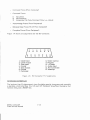
Figure
800XL Computer
Field Service Manual
1-1.
System Block Diagram
1-2
~
To: Monitor
The keyboard connects
The keyboard
to the PC Board by a 24-connector
is the user interface
ribbon cable.
with the computer.
All peripherals connect to the 800XL either through the SIO connector or the PBI.
Power enters through the 7-Pin DIN connector on the rear panel.
RF to the TV
sw itchbox arrives from an RCA phono connector and RF cable. Composite
Video
composite luminance, and audio signals to the monitor arrive from a 5 pin DIN
monitor jack on the rear panel. Power On/Off is controlled by the ON/OFF switch
on the rear panel.
I
I
I
I
Cartridge
Interface
ROM Self Test Enable and BASIC Enable
I
Direction
Control
Controller
Ports
PIA
-
Parallel
Bus
Interface
f.--
..-
POT Control
SIO
Interface
~
..
r-4lo
Keyboard
Trigger
Outputs
Keyboard
I
Address/Control
-r-
POKEY
~
Audio Out
Reset
0: Monitor
Audio
Summation
Circuitry
-...
•..'"
0
-;:
6502C
CPU
--....T
Monitor
Jack
c:
t
Memory
MGMT
Circuitry
J--i
I
Lines
Scan
'"
Cl
""U;~
u '"
c: '"
~"
u..~
r
-
~ c:
I
-I
ANTlC
I-
!+
-I
GTIA
-
Modulator
To: Tele vision
UU
Module Sense
I
4;::1
'0< 0
:J~
c. a
IR•F•
Cartridge
~
:r
Sense
Video
Summation
Circuitry
5V D.C.
Power
On
LED
1
- ; BASIC ROM ~
I
I Operating
Systems ROMs
Up to 16K
DRAMs
! up to 64K
9J
f.--
Figure 1-2. Functional
800XL Computer
Field Service Manual
Power ON Reset
1-3
Block Diagram
f.---
5V D. C.
ELECTRICAL
THEOR Y
DIGITAL HARDWARE
The digital
hardware
consists
of:
o
The 6502C CPU microprocessor
o
The Alphanumeric
o
The Graphics
o
The POT KEYboard
o
The Peripheral
o
The Memory
o
Miscellaneous
Logic
Mernor y Management
Delay Line
o
Parallel
Television
Television
Interface
Interface
Integrated
Interface
Adaptor
Circuit
Adaptor
Controller
(ANTIC)
(GTIA)
(POKEY)
(PIA)
(0.5. ROM, 64K RAM, Atari BASIC ROM, Rev. B)
Bus Interface
Unit (MMU)
(PBI)
6502C CPU Microprocessor
The
6502C
CPU
microprocessor
contains
register
arithmetic
logic, control
logic, and all recognized
characteristics
of the microprocessor
include:
o
Byte-oriented
0
151 opcodes
0
Decimal
0
Seven addressing
0
True indexing
0
Stack pointer
0
Two interrupt
0
64K address
0
Integral
0
Single +5 volt DC power requirement
Figure
flags,
interconnections,
operation
codes.
The
structure
and binary arithmetic
modes
modes
levels
range
clock circuit
1-3 is an iliustration
800XL Computer
Field Service Manual
of the 6502C CPU Pin Assingments.
1-4
~
Ground
ROY Input
Request
.•.5V POWER
!'
h
Phase 2 Clocl<
"
1
!&
sa
Set Overflow
•
17
.:oUNl
Phase 0 Clock
)4
il./w
Read Write
3'
HAd
HALT Input
ro1
,
itbii
,
N.e.
1
~
N.e.
I
n
ce
Data Bus
:a
01
Data Bus
31
oz
Data Bus
Data Bus
'tCC
Address Bus
.U
,
Address Bus
AJ
111
Address Bus
.u
11
JQ
OJ
Address Bus
AJ
11
~
0.
M
l'
:s
OJ
Data Bus
1-
"d
06
Data Bus
r:rI
Data Bus
Address Bus
Address Bus
'"
6502C (MODIFIED)
Data Bus
Address Bus
A6
l'
.:6
Address Bus
113
16
~
AU
Address Bus
A.I
17
:.
At_
Address Bus
Address Bus
'"
La
n
.0.13
Address Bus
Address Bus
AJII
l'
Z%
A12
Address Bus
Address Bus
AU
::SI
21
~
Ground
Address Bus
Figure
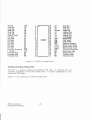
Alphanumeric
Television
1-3.
Interface
6502C CPU Pin Assignments
Controller
(ANTIC)
The ANTIC Display
Processor
is a custom
display
microprocessor
instruction
set customized
for graphics
generation.
It also has the
control the ADDRESS & DATA bus and RAM Refresh.
Figure
Reset
1
N.C.
Non Maskable Input
~
itOY
Phase 1 Clock
In terrupt
04
1-4 is an lllustr ation of the ANTIC Display
800XL Computer
Field Service Manual
1-5
Processor
with
ability
pin assignments.
an
to
GROUND
Alphanurn.
ANa
ANt
Alphanurn, Data
tIght
r1'
E'en
Alphanurn,
(SYS ssn
Data
Interrupt Output:
6
N,\H
7
3/J
3
9
10
33
32
31
30
29
3'
Interface
22
20
21
VCC
5V ?owe!'
A.."rrIC
1.5
ANTIC Display
Adaptor
Al;.
ZJ
26
2S
.-\3
Z~
Processor
1-5 is an illustration
800XL Computer
Field Service Manual
D~
(/)2
28
A6
A1
Pin Assignments
(GTIA)
The GTIA interfaces
with the ANTIC processor
on one side
summation
circuitry
on the other.
Its primary
task is to
luminance
signals from the bit stream
it receives
from
Processor.
It also processes
the Function keys, provides the
the TV speaker and monitors controller
Trigger lines.
Figure
?ha.sa 0 C!odc
AS
A9
All
16
17
1-4.
C/)O
D3
D2
D1
Reset
Fast Phase 0 Clod<
n
ROY
AIO
A12
Alt;.
Al"
ill
F<bO
18
t9
R/W
12
13
it;.
AU
D6
D7
Data :31.13
Data B~
Data Bus
Data aWl
Data Bus
Data. Bus
Data. 8us
Data Bus
l?h~ 2 C!ode
Addrees OllS
Address Bus
Address Bus
Address Bus
Addr~
Bus
Addr~
6us
Addr~....s Bus
11
i~tS
Television
Dj
s
A2
Al
Figure
D4
R~Ml
A.3
ow
4{j
39
33
37
36
ANi
HAJ..T
HAL!
Address Bus
Addr~
Bus
Addrees Bus
Addr ezs Bus
Read/Write
Ready Output
Addre~ Bus
Addr~
Bus
Addr~~ Bus
Address Bu:s
Address
•
1f,
REF
Ref:r~
Graphic
1
2
3
VSS
Data
of the GTIA pin assignments.
1-6
and with the video
generate
color and
the ANTIC Display
keyboard "beep" via
Address Bus
Address Bus
GI"ound
Data Bus
Data Bus
Data Bus
Data Bus
Trigge:f" 0
Tdgge:f" 1
01
6
3'
06
TI
D~
7
&
34
D7
33
R/W
T1
']
32-
CS
T2
10
11
12
13
14
A~
VSs
T:3
51
Sl
Click
~AL Color DC!lay
Color Delay
Alp.hanum. Data O.
Alphanum. Data I
Alphanurn, Data 2
S2
S3
PAL
CADJ
ANO
ANl
AN2
Integrated
Circuit
A2
04
0'
Lurn 3
30
(/)2
29
23
OSC
F<1JO
Address Bus
Address Bus
Address Bus
Data Bus
Data Bus
Data Bus
Data Bus
Read/wrr-te
Clip Select 1
Luminance
VCC
HALT
Po we!"
26
16
l7
13
V
CSYNC
24
22
LUM2
LUM 1
LUM !l
21
eOL
Output Sync:
Luminance 2 Output
Luminance 1 Output
Luminance 0 Output
CuIor
27
n
_
HALT
GTIA Pin Assignments
(POKEY)
The POKEY is a custom Large Scale Integrated
circuit (LSI) chip.
It is used for
audio generation,
Serial Input/Output
(510) Data and Clocks,
POT Controller
interface
scan, and keyboard scan.
Figure
1-6 is an illustration
800XL Computer
Field Service Manual
Line
Phase 2 Input
Clod< Out
o scilla tor Input
U
19
1-5.
n
GTIA
20 ••.•
Figure
POT KEYboard
•
4-
03
Tdggef" 2
Trigget' 3
Option
Start
Select
Kevbcard
A3
A4
02
,
q.Q
39
38
37
36
1
2
3
Al
of the POKEY pin assignments.
1-7
Vss
D3
o If.
c.-cuod
Data Bus
Data Bu:s
Data Bus
Data Bus
Data Bus
06
,
D7
~
02
7
3
9
?3
flot $em
l?ot Sc:sn
20
?t
Response
, V ?owe!"
Keybea.L-d ~
K~beard Sc::u1
Key1::oard $c:;:n
If,
26
pry
Interface
02
D1
3&
DO
Data Bus
37
AUQIO
AO
Audio Cut
36
3'
3If.
33
32
31
At
,-\2
A3
R/W
CSl
LO
l?'
?2
30
~
23
SOD
m
11
12
1.3
l~
l.j
l6
ZS
eczx
zr
17
ZI;
ra
2J
19
22
20
21
'Ice
Rt
KJ
Adaptor
roKEY
Data Su.s
39
E'1f.
Figure
Peripheral
q..o
•
3
D'
?1-a.•'!' 2 Code
Pot $an
Pot $can
Pot Sc:!n
Pot Scan
Pot Scan
?of: .5c:::u1
Keyboard
1
'2
2'
zr
~
IRQ
ACl.K
m
STO
RQ
K!
iC!
Data 9us
Addr'e=:s Bus
Addre::s Bus
Ad~B'..ls
Ad~
Se.s
ReadlWrit'e
Cl~Se~
Chip~
intem.!.p1: Request
S~W Ctl'tt'trt: Da.ta
Se!:'ial Cut;)ut' C!odc
Bid~nal
<:::ode
Keyboard Response
Sef'lal Input Da:ti,
Keyboard Sc::3n
KeyOOa..rd $em
Keybca.r'ti Scan
1-6. POKEY pin assignments
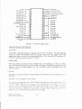
(PIA)
The PIA is a general
purpose Input/Output
(I/O) chip.
It monitors
the X- Y
controller
interfaces
and the SIO control lines.
In certain
applications
it may
control the MMU logic.
Figure
1-7 is an illustration
800XL Comouter
Field Servic'e Manual
of the PIA assignments.
1-8
Ground
Controller !nput
,.v
Con troller Input
?'U
Contro!ler Input
?..:
Controller
Inpur
Controller Input
CAZ
Motor Control Output
-
~
Interrupt
Request (Cut;lu:i
-
~
Interrupt
Request (Output)
.~
-
Al
Address Line
•.••
_
A(/J
~
Address Line
Reset Input
Data Line
-
Con troller Input
'AJ
Controller
.M
011
'AZ_
aa
Data Line
CII
Data line
Input
Controller mput
Enable/Disable
Output ?¥
Not Used
-
~
Output To Led I ••
OJ
Data line
0-
Data line
Not Used
""
OJ
Data Line
Not Used
••••
06
Data line
Not Used
~
':II
,'lot Used
?S
Sell Test Output
Data Line
Clock Input
/"!!II
Control Line cu'::=C"'om~m---an-:d
Output C!IZ Supply Voltage >0:_
;., Volts
I.
Chip Select Input
"
Chip Select Clock Input
Chip Select Input
~
Figure
r-
1-7.
Read/WiTte
PIA Pin Assignments
MEMORY (ROMS AND DRA"AS)
0.5. ROM
The 800XL operating system is resident in one 16K X 8 ROM. The ROM address
inputs are from CPU address lines AO through A13. The chip selects from the
address decoding circuitry
and generates
data on CPU data lines DO through 07.
The RO\.'\ requires a power input of +5 volts.
BASIC ROM
The Atar i 800XL has built-in Atari BASIC (Rev. B) residing in an 8K X 8 ROM,
This is equivalent to having an Atari BASIC cartridge
permanently
plugged into the
console.
Any cartridge
plugged into the computer,
takes precedence
over the
built-in BASIC.
DRAMS
The 800XL
Dynamic
Random
Access
Memories
(DRAMS)
consist
of eight
6~lK X
DRAMS.
MEMORY MANAGEMENT UNIT (MMU)
The memory management
unit (M,\1U) address decoding circuitry consists of a PL/\.
(Programmable
Logic /\rray ) L.C:t5 one 3 to 8 decoder and a fe\v gates,
'The Input
to the circuitry
includes the address lines /\.8 through Ai 5 as well as control
signals, such as RO~J1 enable (fro rn PIA) and DRf\M refresh from i\rJ1"IC.: Some of
the most important outputs of this circuitr y include select signals for the CTIA,
POKE\r~ PIA? OS ROM? DRAMS? BASIC and car tr idge.
800XL Computer
Field Service Manual
1-9
RF \t\ODULATOR
The RF modulator accepts the composite video from the video summation circuitry
and the mono-aural
audio signals and produces a modulated
signal suitable for the
television.
With a 75 Ohm termination,
Maximum Voltage:
Mini mum Vol tage:
Audio Sound Carrier
the modulated
signal has the following
characteristics:
2MV
1MV
Frequency:
4.5 MHz
Frequency Response:
Channel 2 Band: 6 MH~
Video Carrier: 55.25 MHz
Audio Carrier: 59.75 MHz
Channel 3
Band:
Video
Audio
6 MHz
Carrier:
Carrier:
61.25 MHz
65.75 MHz
MONITOR OUTPUT
The 5 pin DIN monitor output
jack (J2) accepts
the composite
video and the
composite
luminance
signals from the GTIA video summation
circuitry
and the
amplified
mono-aural
audio signals from POKEY.
J2 then transfers
these signals
directly to the input of the video monitor via a 5 pin DIN monitor cable.
The output
signals
have the following
Composite Video
Composi te Luminance
Audio
characteristics:
Min. Voltage
750 MV P-P
1.2V P-P
600 Mv P-P
Max. Voltage
1 V P-P
1.5V p-p
750 Mv P-P
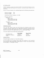
POWER SUPPLY
The power supply connector
is a 7-pin DIN connector.
The Atari 800 XL has an external
power supply that accepts
110 VAC (nominal)
from the power lines and provides +5 VDC output (+/- 2%). The maximum rating
for the supply is + 5 volts and 1.2 amps.
800XL Computer
Field Service Manual
1-10
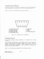
Figure
1-8 is an illustration
of the power supply connector
-1'----,:;;- •.5 Volts
GndReturn-~--ir-*
Figure I-S.
pin assignments.
Power Supply Pin Assignments
(Looking Toward Computer)
SYSTEM INTERFACE
The 800XL provides the following interfaces:
o
Serial input/output
o
Keyboard Interface
o
Controller
o
Cartridge
o
Parallel
(510)
Jacks
Interface
Bus Interface
SERIAL INPUT/OUTPUT
(PBI)
(SIO) INTERFACE
The Atari 800XL communicates
with peripheral devices via an asynchronous serial
port (i9.2K Baud rate max.).
Data is transmitted
and received as eight bits of
serial data. LSB is sent first preceded by a logic zero start bit and succeeded by a
logic one stop bit. The serial data out is transmitted
or received as positive logic.
The serial data out line always assumes its new state when the serial clock out line
goes high. Clock out goes low in the center of data out.
The bus protocol specifies that all commands must originate from the computer
and that peripherals present data on the bus only when commanded to do so. Every
bus operation goes to completion before another bus operation
in initiated.
An
error detected at any point in the bus operation aborts the entire sequence.
A bus
operation consists of the following elements:
800XL Computer
Field Service Manual
1-11
Command
Frame
Command
Frame
1)
2)
3)
Data Send
Data Receive
Immediate (No Data-Command
Acknowledge
Optional
Frame
Data Frame
Complete
Figure
(From Computer)
Frame
Only, i.e., status)
(From Peripheral)
(To Or From Computer)
(From Per ipheral)
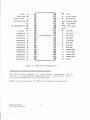
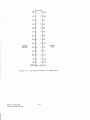
1-9 shows pin assignments
2
for the SIO connector.
4
6
8
10
12
• • • • • •
•3 •5 •7 •9 11•
1.
2.
3.
4.
5.
6.
7.
Clock Input
Clock Output
Data Input
Ground
Data Output
Ground
Command
Figure
KEYBOARD
1-9.
8.
9.
10.
11.
12.
13.
SIO Connector
Motor Control
Proceed
+5/Ready
Audio Input
Not Connected
Interrupt
Pin Assignments
INTERFACE
The keyboard has 55 alphanumeric
keys (including special characters
a spacebar, which interface
thru U24 and U25 Keyboard Sense/Scan
function keys, and a RESET key.
800XL Computer
Field Service Manual
1-12
and controls),
Decoders, four
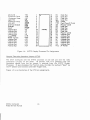
CONTROLLER
JACK INTERFACES
The SOOXL provides
electrically
identical.
two controller
The controller
jack interfaces.
Both are functionally
jacks are 9-pin D-type male connectors.
Figure 1-10 shows the pin assignments
1
•
for the 9-pin connectors.
2
4-
3
•
5
•
••
•6 •7
•8
•
•9
1. (Joystick Forward Input
2. (Joystick) Back Input
6.
7.
S.
9.
3. (Joystick) Left Input
4-. (Joystick) Right Input
5. B Potentiometer,
Input
Figure 1-10.
and
Controller
Trigger Input
+5 volts
Ground
A Potentiometer
Input
Jack Pin Assignments
CARTRIDGE INTERF ACE
The cartridge
connector.
interface
connects
cartridges
to
the
computer
with
a 30-pin
The Atari 800XL has Revision B of Atari BASIC built-in.
This is equivalent to
having a BASIC cartridge
"permanently"
plugged into the console.
When any
cartridge
is plugged into the computer,
it takes precedence
over the built-in
BASIC. This is a function of hardware.
When no cartridge
is plugged in, the
hardware enables the built-in BASIC.
Figure 1-11 illustrates
SOOXL Computer
Field Service Manual
the pin assignments
of the cartridge
1-13
connector.
54
1
A
R04
A3
2
B
GND
A2
3
C
A4
Al
4
0
AS
A~ S
E
A6
6
F
A7
05 7
H
A8
02 8
J
A9
9
K
A12
O~ 10
L
03
06
11
M
07
55
12
N
All
+5V 13
P
A10
04
01
CONSOLE
BOTTOM
ROS
14
CCNTL 15
Figure 1-1l.
800XL Computer
Field Service Manual
Cartridge
CONSOLE
TOP
R R/W
S
B0Z
Connector
1-14
Pin Assignments
PARALLEL
BUS INTERFACE
The parallel bus interface
(PBI) provides an un-buffered,
direct connection
to the
address, data and control signals shown below.
It could be used to interface
peripherals,
parallel bus devices and external applications.
Figure
1-12 illustrates
the pin assignments
of the parallel
bus interface.
Parallel Bus Specification
GROUND
GND
1
2
EXTSEL' (EXTERNAL
Al (ADDRESS OUTPUT)
SELECT)
(ADDRESS OUTPUT)
AO
3
4-
(ADDRESS
A2
5
6
A3 (ADDRESS OUTPUT)
A4-
7
s
A5 (ADDRESS
OUTPUT)
(ADDRESS OUTPUT)
OUTPUT)
OUTPUT)
A6
9
10
GND
(AODRESS OUTPUT)
A7
11
12
A8 (ADDRESS
(ADDRESS
A9
13
14
AI0 (ADDRESS
OUTPUT)
All
15
16
A12 (ADDRESS
OUTPUT)
(ADDRESS OUTPUT)
A13
17
18
A14 (ADDRESS
OUTPUn
GROUND
GND
19
20
A15 (ADDRESS
OUTPUT)
DAT A. 51-DIRECTIONAL
DO
21
D1 (DATA-BI-DIRECTIONAL)
DA T A Bl-DIRECTIONAL
D3 (DA TA-BI-OIRECTIONAL)
DA T A 51-DIRECTIONAL
D2
Di>
22 ~
0
24 Ir26
£
05 (DA T A-B1-DIRECTIONAL)
DATA 51-DIRECTIONAL
D6
2S,
U.l
07 (OAT A-BI-DIRECTI0NAL)
(ADDRESS
OUTPtJT)
(ADDRESS OUTPUT)
.
0..
23
0
r- 25
Ll.l
27
-l
-l
0
GROUND
GND
PHASE 2 CLOCK-OUTPUT
802
N/C
INTERRUPT
RESERVED
REQUEST INPUT
IRQ
OUTPUT)
0
~ 29
30
<.I')
8 31
32
8
33
34
RST' RESET OUTPUT
35
36
ROY READY INPUT
38
4-0
EXTENB EXTERNAL
GND GROUND
z
GND GROUND
GND GROUND
N/C
RESERVED
37
N/C
RESERVED
39
COLUMN ADDRESS-OUTPUT
CAS'
41
MA TH PACK DISABLE-INPUT
MPD'
4-3
42
4-4
GND
4-5
4-6
LR/W' LATCHER
RESERVED
t;.7
t;.8
RESERVED N/C
49
50
GND GROUND
GROUND
N/C
AUDIO IN
AUDIO
Figure
800XL Computer
Field Service Manual
REF'REFRESH-OUTPUT
RAS' ROW ADDRESS STROBE (OUTPUT)
1··12. PBI Connector Pin Assignments
(Looking into the Computer)
1-15
DECODER-OUTPUT
READ!WRITE-OUTPUT
SECTION 2
TESTING
OVERVIEW
This section describes the procedures
available for testing and troubleshooting
800XL. They are:
o Self Test
o SuperSAL T Diagnostic Cartridge and SuperSALT Test Assembly
EQUIPMENT
o
o
o
o
o
the
NEEDED
800XL Computer console with accessories
TV set, properly adjusted
SuperSAL T Diagnostic Cartridge (FD100335)
SuperSALT Test Assembly (FAl 00332)
Super Sa LT Technical User's Manual (FOI 00770)
SELF TEST PEA TURES
The Self Test feature allows minimal testing
of the following
o Memory - RAM, ROM and ANTIC
o Audio/Visual - ANTIC, GTIA, and POKEY
o Keyboard - POKEY and ANTIC
NOTE: Remove
any cartridge
from the unit.
To enter the testing sequence, press and hold the OPTION
turned on. The Self Test menu screen will appear.
To exit the test? press
appear on the screen.
the
components:
SYSTEM
RESET
key; the
key while the console
Basic
Ready
prompt
is
will
NOTE:
Pressing the HELP key has no effect in any situation,
except possible
future application
programs and as an exit from individual test to return to Self
Test menu,
Procedure~
1. Connect the computer console to TV set as shown in owner's manual.
2. Turn on TV set.
3. Press and hold the OPTION key as the computer
is turned on until the Self
T est menu appears.
u, The Self Test Menu displays four options:
o
Memory
o
Audio Visual
o
Keyboard
o
All Test
800XL Computer
Field Service Manual
2-1
Press
test.
the SELECT
ke y to move the selection
indicator
until you reach
the desired
Press the START key to begin the test.
CAUTION:
Self Test will not go into the Attract
screens on for any length of time
screen burning can occur.
DESCRIPTION
Mode. 00 not leave Self Test
(maximum
seven minutes),
since
OF SELF TESTS
MEMORY TEST
Purpose:
To test
the ROM, RAM, and ANTIC chips.
F orrnat:
Two long bars displayed at the top of the screen represent
the 16K
:)per ating System RO\L
Below them are 48 blocks, each representing
1'< of Ri\M.
The remaining
16K of RAM is available only 'with certain
software
programs and is not tested at this time.
When either ROM or
RAM is being tested, the corresponding
bar segment color is white •. If
the ROM or RAM tests good, the bar color changes to light green.
If
the ROM or RAM tests defective,
the color changes to red.
Once a
ROM or RAM has been tested and found defective
the bar or specific
block remains red and the memory is not tested again on subsequent
test passes.
The 'v1EvlORY TEST continues
pressed.
NOTE:
testing
until
either
the
HELP
or RESET
key
If RESET is used to exit a test, the OS will return to Basic not the Self
Test. You must then press and hold OPTION and power up the console
'clefore.
is
as
AUDIO VISUAL TEST
Purpose:
To test the ANTIC and POKEY chips.
Format:
The screen displays a music staff and treble clef. A sequence of six
tones sound and the corresponding
note shows on the staff.
The tune
plays sequentially
from channel one through channel four. The channel
number changes for each according to the sound channel in use. Voice
numbers 1-4 under the staff and treble clef indicate the channel in use.
There is a slight pause between each voice.
A fault is indicated
by a
note appearing on the screen without any sound and vice versa.
The AUDIO VISUAL TEST continues
pressed.
KEYBOARD
testing
until either
the HELP or RESET key is
TEST
Purpose:
To test the POKEY, ANTIC and ROM chips
Format:
A full keyboard is displayed on the screen.
Press each keyboard key and
the corresponding
key on the screen changes to inverse video and a tone
sounds, It should change back to the original color when the key is
800XL Computer
Field Service Manual
2-2
released.
NOTE: The can tr ol and shift keys change onl y when pressed
at the same time as another key. The display for both keys will change
to inverse video and then back.
As each key (except RESET, HELP ,~
BRE/\K) is pressed, a tone is generated.
ALL TESTS
All of the Self Tests
RESET key is pressed.
NOTE:
are executed
one after
another
until
either
the
HELP
or
When ALL TESTS is executing,
the MEMORY TEST and the AUDIO
VISUAL TEST exit after one complete
test cycle.
KEYBOARD TEST
during ALL TESTS is software controlled.
No operator input is required.
SUPERSAL T TESTING
For
(PIN
SuperSAL T testing
FDI00770).
800XL Computer
Field Service Manual
procedures
refer
2-3
to SuperSAL T Technical
User's
Manual
SECTION 3
SYMPTOM CHECKLIST
The Symptom Checklist is designed to aid the technician
in arriving at, listed in the order of
failure, rapid diagnosis of problems.
Each symptom is accompanied
by some possible causes,
and suggested
remedies.
Instructions
for disassembly/assembly,
are in SECTION 4- of this
manuals
SYMPTOM
POSSIBLE CAUSES
REMEDY
Snowy Screen
TV Switch Box, ON/OFF
switch, Channel Select
switch, RF Modulator
Adjust or replace.
Defective
Damaged
Replace
Black/Grey
Screen
Power Supply,
RF Cable
Defective (open) components
on +5C line.
Isolate
and replace
Defective (shorted) components
on +5A, Band/or Clines.
Isolate
and replace
Defective (shorted)
and/or Ie's
Isolate
and repair
LSI's
YI, Q89 9, CI09
Troubleshoot
the clock
circuit and replace
defective component.
U2, 7-20, 22, 23, 26-30
Isolate and replace
defective IC
Red/Brown
Isolate and replace
defective IC
Blue screen
U2
Replace
Yellow screen
un
Replace
No Color or Bad Color
RF Modulator
800XL Computer
Field Service Manual
or R38
Adjust or replace
U 17, U20, Ql, Q3, CR2, CR3
Troubleshoot
color /video
circuitry.
Replace defective IC/component.
YI
Verify 3.579545 MHz freq.
of Yl. Replace if defective
3-1
SYMPTOM
POSSIBLE CA USES
REMEDY
No Power Light (Ll)
Power LED, Power Supply,
Cables
Repair
or Replace.
No Gray Bars or
Missing Bar
U17, U20
Repair
or Replace.
Upside down Alpha/
Numerics on Player
Field
U7
Replace.
Some Keyboard
U22, Keyboard,
Ail Keyboard
Keys Fail *
Keys Fail *
T one or Tones 'vi issing
During Tone Test
U24-, U25, Cable
U22, 24. 25
U22,
or Replace.
Repair or Replace.
!f..5\rlHz,
Carrier
Repair
ui,
Frequency,
Audio
TV volume
Repair , Adjust
4-.5 MHz on RF Modulator.
Replace if necessary.
Console Game Switches
Will Not Functon
U 17, Keyboard,Cable
Repair
or Replace
ROM Test Failed
U2-U5
Repair
or Replace.
RAM Test Failed
U2, 3, 9-16, 18, t 9, 26-30
Verify ANTIC is Rev E.
Repair or Replace.--
Video or ANTIC
Stress Fail
U7
Repair
CPU Test Fail
Yl,Q8,
2-Way Clock Fail**
Jl, U22
Repair
or Replace.
External
Jl, Ul
Repair
or Replace.
U17
Replace.
Audio* *
GTIA Fail
* Keyboard
and switch
require
Verify 3.58 MHz osc.
frequency.
Repair or Replace.
Q9, U8
operator
or Replace.
intervention.
* * Requires
the SuperSALT
Test Assembly,
jumper
cables,
power supply for correct
operation.
Joystick and Paddle Test require user action with a joystick and paddle during
respecti ve testing.
800XL Computer
Field Service Manual
3-2
SYMPTO\~
POSSIBLE CA USES
REMEDY
I/o Port Test Failures
Voltage:
Pi, P2
L25 J5, J6
Inspect J 5, 6 for
damaged pins; replace
as necessary
Voltage:
Me
Q7,L11,U2
Repair
or replace
Repair
or replace
j
PIA Ports
U23, C26-29,
L19-22
S10 Port
U22, U23, C75-78
Repair
or replace
U 17, L23, L30, C96, C97
Repair
or replace
POT Lines
U22, L15-I8,
C63-66
Repair
or replace
Timers
U22
Trigger
Lines
800XL Computer
Field Service Manual
C82-92
C71-74
Replace
3-3
SECTION 4
ASSEMBL Y /DISASSEMBL
Y
Disassembly
Hardware
o
o
o
o
***
Access
Turn unit upside down.
Remove six screws from bottom cover.
Turn unit upr ight.
Tip cover by raising the left side allowing access to the keyboard cable.
Carefully
disconnect the keyboard ground strap and remove the keyboard cable from its socket
and lay top aside.
Due to incompatibility of plastic housings, do not interchange top or bottom housings
between units. Keep the housings which belong to each unit with that unit,
PCB Removal
o
o
o
Remove the four remaining screws holding the PC Board.
Lift up on the front of the PC Board while pushing out on the right side of the bottom
housing; (player port side) until the player ports clear the bottom housing.
Remove the PC Board.
Assembly
Reassemble
in reverse
800XL Computer
Field Service Manual
order.
4-1
SECTION 5
SCHEMA TICS AND SILKSCREENS
AND PARTS LIST
The schematic and silkscreen for the 800XL are attached
manual.
Remove them and place in this section.
NOTE:The schematic
dotted boxes.
troubleshooting
This section
contains
is a domestic/U.K.
READ the notes
is performed.
the complete
800XL Computer
Field Service Manual
version.
at the
to the front
All U.K. additions are shown in
bottom
left corner
before any
Parts List for the 800XL.
5-1
cover of this
SECTION 5
PARTS LIST
Location
Description
Part Number
Console Assembly
Door, Cartridge
Bar, Door
Spr ing, Door
Keyboard
C024582-001
C024680-00 1
C024681-00l
C06l983
Power Supply
CA0248 t 4-00 1
T. V. Switchbox
Al
C1
C2,3,10,
79
C4,7,11,
13,94,95
C5,6,8,9,
12,1£;,15,
21,46,47,
5£;,71-78,
80-92,96,
97,102,112
C16,l8,2532,34-43,
48,51,57,
62,68-70,
93,105-109
C17,23,6366
C19,20,22
C24,50,98
C44
800XL Computer
Field Service Manual
(Pkgd)
CA014746
RF Cable
CA024624-00
PCB Assembly
Cartridge Guide
Shield, Top
Shield, Bottom
C060297
C024467 -001
C024468-00 I
Modulator, Domestic
(UMI652)
Cap. Elec. Axial 470uF (10'1)
Cap. Elec. Axial 22uF (16V)
C014370
C014393
Cap. Ceramic
Axial .OluF (25V)
C014181-02
Cap. Ceramic
Axial .G01uF (50V)
C014181-01
Cap. Ceramic
Axial .1 uF (25V)
C014181-03
Cap. Ceramic
Axial .047uF (50V)
C014180-09
C06I619
Cap Nonpolarized
4.7uF (35V)
Cap. Elec. Alum 10uF (16V)
Cap Ceramic Axial 68pF (50V)
5-3
C0616£;7
C014371
C014179-12
1
PARTS LIST
Location
Description
Part Number
ce s
Cap Ceramic Axial 220pF (50V)
Cap Elec Axial ll7uF (lOV)
Cap Ceramic Axial 100pF (50 V)
Cap Ceramic Axial 3.9pF
Diode (1 N4l48)
Connector,
R t .. -\ngle (13 pin)
Connector,
'vlonitor (5 pin)
Connector,
Cartridge (30 pin)
Connector,
Rt. Angle (9 pin)
Connector,
DIN Power (7 pin)
Connector,
Keyboard Header
(24 Pin)
Inductor Ferrite Bead
C014180-05
2ll-100476
C014179-19
C061336-01
C060607
C)12995
C')14388
C014389
C010448
C061838
C061793
Inductor Axial 820uH
Inductor, Axial 100uH
Inductor, Axial 10uH
Inductor ,Axial 22uH
Transistor,
NPN (2N390ll)
Transistor,
PNP (MPSA55)
Transistor,
PNP (2N3906)
Resistor, 1/4'11 2.2K
Resistor, 1/IlW 2K
Resistor, 1/llW 6.2K
Resistor, 1/ll W 56K
Resistor, 1/4'11 470K
Resistor, 1/4 W 68 K
Resistor, 1/4'11 5.1 K
Resistor, 1/llW 3.3K
Resistor, 1/4 W 1K
C0179ll8-03
CO179ll8-04
COlll381
COlll380
34-2N3904
COlll809
C018991
14-5222
14-5202
14-5622
14-5563
1ll-5ll74
11l-5683
lll-5512
1ll-5332
14-5102
Resistor,
1ll-5302
C4-9
C52,55
C53
CRl-5
31
32
J4
J5,6
J7
J8
Ll-3,7,9,
11,12
L4,5
L6
Ll 0,15-30
Ll4
Q1-5
Q7
Q8,9
Rl,11,59
R2,7,52
R3,58
Rll,39
R5
R6
R8
R9,62
RIO,13,14,
37,41-45,
60,61,80,97
R12,15,16
19-22,3134,68,74,
75,85-88,
106
R17,65
R18
R23-30,64
R35
R36
R38
800XL Computer
Field Service Manual
Resistor,
Resistor,
Resistor,
Resistor,
Resistor,
Resistor
1/ll W 3K
1/4W 240
1/ll W 1 M
1/4W 10K
1/4W 33K
1/4 W 680
Variable (Trimpot)500K
5-4
C01438ll
lll-52ll1
14-5105
14-5103
lll-5333
1ll-5681
19-411504
PARTS LIST
Location
Descr iption
Part Number
R40,53,66
90,109,112
117,119,128131
R46
R47
R48
R49
R50,63,81-84
92-94
R51
R54
R55,56,57
R89
R76-79
R91
R9 5,110,118,
120-127,132
133
R98-105,107,
108
Rl1l
RI13,134-137
R114
Rl16
RNl-4
Sl
52
Ul
U2
U3
U4
U5
U7
U8
U9-16
Ul7
U18
U19
U20
Resistor
1/4 W 100 Ohm
14-5101
Resistor
Resistor
Resistor
Resistor
Resistor
1/4 W
1f4. W
1/4W
1/4 W
1/4 W
1.6 K
36K
18K
9.1 K
4.7K
14-5162
14-5363
14-5183
14-5912
14-5472
Resistor
Resistor
Resistor
Resistor
Resistor
Resistor
Resistor
1/4 W
1/4 W
1/4W
1/4 W
1/4 W
1/4 W
1/4 W
750 Ohm
1.2K
75 Ohm
47K
1.8K
2.7K
220 Ohm
14-5751
14-5122
14-5750
14-5473
14-5182
14-5272
14-5221
Resistor
1/4 W 33 Ohm
800XL Computer
Field Service Manual
14-5330
Resistor 1/4 W 27 Ohm
Resistor 1/4 W 470 Ohm
Resistor 1/4 W 1.5K
Resistor 1/4 W 51 Ohm
Resistor Network SIP 470 Ohm
Switch Vertical Power (SPDT)
Switch Channel Select
IC Dual Op Amp (LM358)
IC Decoder (74LS138)
IC Mem Mngt Unit (MMu1 B)
IC (16K X 8) OS ROM
IC (8K X 8 ROM) Rev B
IC ANTIC
IC CPU (6502)
IC (64K X 1 DRAM)
IC GTIA
IC AND Quad (74LS08)
IC Hex Inverter (74LS14)
IC Hex Buffer CMOS (CD4050B)
5-5
14-5270
14-5471
14-5152
14-5510
C06l668-04
C061022
C019702-01
C061702
C061428
C061618
C0615~8
C060302
C021697
C014806
C060612
C014805
C017097
C061850
CO10816
PARTS LIST
Location
Description
Part Number
U22
U23
U24,25
U26,27
U28
U29
U30
Wl
XUI
XU18,19,30
XU2,9-16,
20,24-28
XU3
XU4,5
XU7,8,17,
22,23
Yl
IC POKEY
IC PIA
IC MUX (CD4051 B)
IC Multiplexer (74LS158)
IC Latch (74LS375)
IC Delay Module
IC AND/oR Inverter (74LS51)
Resistor 1/4 W 0 Ohm
Socket IC (8 pin)
Socket IC (14 pin)
Socket IC (16 pin)
C012294
C014795
C014336
CO 14345
C060619
C060472
C060471+
C060629
C014386-0l
C014386-02
C014386-03
Socket IC (20 pin)
Socket IC (24 pin)
Socket IC (40 pin)
C014386-05
C014386-07
C014386-09
800XL Computer
Field Service Manual
Crystal
3.579545
C061090
MHz
5-6
SECTION 6
SER VICE BULLETINS
This section is to be used by you to file the three classifications
are periodicaUy released by the Director of Technical Support.
The following
are brief descriptions
of service
bulletins
that
of each classification:
FIELD CHANGE ORDER
'\ Field Change Order describes
mandatory
hardware
products and instructs how to implement these changes.
on all units serviced or repaired.
UPGRADE
or software
The changes
changes to /\ TARI
must be performed
BULLETIN
An Upgrade Bulletin describes product improvements
or modifications
that the consumer
may wish to purchase.
These bulletins allow you to modify the customer's
unit to add
capabilities
which may not have been available
when the unit was originally
manufactured.
TECH TIP
A Tech Tip is a document of a general nature which transmits
routine service or repair
information.
By communicating
methods developed since you attended
training classes,
Tech Tips aid to continuously
improve repair skills and increase knowledge of ATARI
products.
Other times, Tech Tips alert you to units that have been modified and are now standard
for AT ARI Manufacturing,
but are different
from many existing
units and require
different repair techniques.
800XL Computer
Field Service Manual
6-1