1
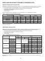
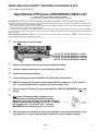
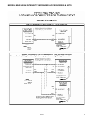
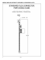
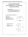
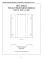
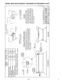
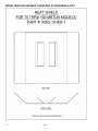
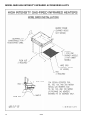
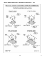
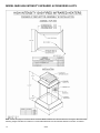
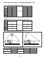
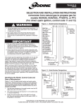
9-510 January, 2008 INSTALLATION INSTRUCTIONS accessories and kits for high intensity infrared model MHR ACCESSORY PARABOLIC RELFECTOR EXTENSION TABLE OF CONTENTS Natural to LP Gas Conversion Kits………………….. High Altitude Conversion Kits………………………… Two Stage Microprocessor Room Thermostat…….. Stainless Steel Gas Connector with Shut Off Valve.. Chain Mounting Kit……………………………………. Heat Shield – MHR30 through 60…………………… Heat Shield – MHR70 through 100………………….. Wire Re-Radiating Grid……………………………….. Protective Screen……………………………………… Parabolic Reflector Extension………………………... WARNING Gas supply shall be shut-off and the electrical power disconnected before proceeding with the conversion. Failure to do so could result in fire, explosion, electrical shock, or the unit starting suddenly resulting in injury. IMPORTANT 1. The use of this manual is specifically intended for a qualified installation and service agency. All installation and service of these kits must be performed by a qualified installation and service agency. 2. These instructions must also be used in conjunction with the Installation and Service manual originally shipped with the appliance being converted, in addition to any other accompanying component supplier literature. 2-3 2-3 4-5 6 7 8-9 10-11 12 13 14-15 MODEL MHR HIGH INTENSITY INFRARED ACCESSORIES & KITS Natural to Propane Gas Conversion Kits Model MHR units with direct spark ignition (Control Codes 47, 48, 97, 98, 38, and 88) can be converted from Natural Gas operation to Propane (LP) Gas operation with a field installed kit. Table 2.1 indicates the combinations available. Each kit comes with: • • • • A Conversion Checklist to instruct the installer how to make the conversion (see following page) A Serial Plate sticker to identify that the unit has been converted An appropriately sized orifice(s) An orifice wrench Note that a regulator spring kit is not required; the valve can be adjusted to 10” W.C. manifold pressure as supplied. Table 2.1 – Natural to LP Gas Field Conversion Kits Gas Control Type: Convert from Natural Rating: Single Stage Two Stage 30 or 60 100 120 or 160 120 or 160 100/50 150/100 200/100 50 90 120 160 90/45 120/80 160/80 54287 54288 54289 54290 54288 54289 54291 To Propane Rating: Kit Item Code Kit Description 50L 90L 120L 160L 90L 120L 160L/80L Orifice Size Orifice Qty Used 1.8mm 1.8mm #50 1.8mm 1.8mm #50 1.8mm 1 2 3 3 2 3 4 Example: To convert an MHR 60 S 47 to be suitable for use on propane gas, Kit Item Code 54287 from Table 2.1 is used to convert the size 60 to a size 50 for use with propane. High Altitude Conversion Kits Model MHR units with direct spark ignition (Control Codes 47, 48, 97, 98, 38, and 88) can be converted for use at elevations up to 7000 feet above sea level with a field installed kit. Table 2.2 indicates the combinations available. Each kit comes with: • • • • A Conversion Checklist to instruct the installer how to make the conversion (see following page) A Serial Plate sticker to identify that the unit has been converted An appropriately sized orifice(s) An orifice wrench Table 2.2 - High Altitude Field Conversion Kits cd Natural Elevation Above Sea Level (feet) Propane All MBH 50 90 Kit Item Code 4001-5000 Kit Description 6001-7000 160 (single stage) 160/80 54293 54292 54293 H51 H50 H51 Orifice Size #51 #50 #51 Orifice Qty Used 3 3 4 No Kit Required Kit Item Code 5001-6000 120 Kit Description No Kit Required No Kit Required 54292 54292 54294 54293 54294 H50 H50 H52 H51 H52 Orifice Size #50 #50 #52 #51 #52 Orifice Qty Used 1 2 3 3 4 Kit Item Code 54293 54293 54295 54294 54295 H51 H51 H1/16 H52 H1/16 Orifice Size #51 #51 1/16” #52 1/16" Orifice Qty Used 12 2 3 3 4 Kit Description No Kit Required c No kit required for elevations up to 4000 feet above sea level. d If converting from natural to propane AND high altitude at the same time, only the high altitude kit for propane from Table 2.2 is required. Example: To convert a 100MBH natural gas unit for propane operation at 6000 feet, select Item Code 54292 from Table 2.2 for a 90MBH propane unit at 6000 feet. 2 9-510 MODEL MHR HIGH INTENSITY INFRARED ACCESSORIES & KITS Form No.HALP-120/24-CONVLIST High Altitude LP/Propane CONVERSION CHECK LIST 120 VOLT OR 24 VOLT DIRECT SPARK SYSTEMS HIGH INTENSITY (CERAMIC SURFACE) INFRARED HEATER ------------------------------------------------------------------------------------------------------------------------------------------------------------------------Read This First: When repairing or converting a high intensity infrared heater, any substitution used in place of factory approved parts or components will void CSA International (A.G.A. / CGA) certification and all warranties. Failure to comply with this procedure could result in unsafe operation, personal injury, property damage, and/or death. The installing contractor, or person, must be familiar with all the various installation requirements and is personally liable and responsible for this conversion and the unit's compliance with all applicable codes. To maintain CSA International (A.G.A. / CGA) certification and the warranty, the attached Heater Certification Form must be signed and dated by the individual who performed the conversion. It must be returned, immediately, to the Customer Service Department before the units are placed back into operation. 1) Before Attempting Any Conversion: Check that you have all the necessary factory approved components, and off and securely lock out the gas and electrical supplies. 2) as a safety precaution, shut ------------------------------------------------------------------------------------------------------------------------------------------------------------------------- Turn Off Electrical and Gas Supply. 30,000 TO 60,000 BTUH has 1 orifice 70,000 TO 100,000 BTUH has 2 orifices 110,000 TO 150,000 BTUH has 3 orifices 160,000 TO 200,000 BTUH has 4 orifices Remove existing gas orifice(s) from the gas manifold assembly. Clean the manifold pipe threads of any remaining Teflon tape. Install replacement gas orifice(s). Locate existing serial plate and attach new serial plate sticker below it. CHECK: Propane gas line pressure at the heater MUST be between 11.0” W.C. and 14.0” W.C. Connect gas and electric supplies, and turn the heater “ON”. Remove plug at Test Point "B" and install a WATER or RED OIL MANOMETER (not a dial gauge). ALL other LP/Propane burning equipment in the building must be operating at maximum capacity. Remove gas pressure regulator cap from the gas valve. Adjust the gas pressure regulator to 10.0"W. C. Replace the regulator cap. Turn the unit "OFF". Remove MANOMETER and reinstall plug at Test Point "B". After conversion is completed, perform a leak test with a soap and water solution on all gas connections. Proceed with operating instructions in the installation manual. 9-510 3 MODEL MHR HIGH INTENSITY INFRARED ACCESSORIES & KITS 4 9-510 MODEL MHR HIGH INTENSITY INFRARED ACCESSORIES & KITS 9-510 5 MODEL MHR HIGH INTENSITY INFRARED ACCESSORIES & KITS 6 9-510 MODEL MHR HIGH INTENSITY INFRARED ACCESSORIES & KITS 9-510 7 MODEL MHR HIGH INTENSITY INFRARED ACCESSORIES & KITS 8 9-510 MODEL MHR HIGH INTENSITY INFRARED ACCESSORIES & KITS 9-510 9 MODEL MHR HIGH INTENSITY INFRARED ACCESSORIES & KITS 10 9-510 MODEL MHR HIGH INTENSITY INFRARED ACCESSORIES & KITS 9-510 11 MODEL MHR HIGH INTENSITY INFRARED ACCESSORIES & KITS 12 9-510 MODEL MHR HIGH INTENSITY INFRARED ACCESSORIES & KITS 9-510 13 MODEL MHR HIGH INTENSITY INFRARED ACCESSORIES & KITS Note: Please see page 15 of this document and model MHR Installation and Service Manual for changes to Recommended Mounting Heights and Minimum Clearance to Combustible Materials when the Parabolic Reflector Extension is installed. 14 9-510 MODEL MHR HIGH INTENSITY INFRARED ACCESSORIES & KITS Table 15.1 – Changes to Recommended Mounting Height (feet) Model MHR 30 MHR 50 MHR 60 MHR 90 MHR100 MHR120 MHR150 MHR160 MHR200 Standard Reflector 0° Angle 30° Angle 11.0 – 13.0 13.5 – 15.5 14.5 – 16.5 16.0 – 18.5 17.0 – 19.5 17.5 – 21.0 18.5 – 22.5 19.0 – 23.0 20.5 – 25.0 10.0 – 12.0 12.5 – 14.5 13.0 – 15.0 14.5 – 17.0 15.0 – 17.5 15.5 – 18.5 16.5 – 20.0 17.0 – 20.5 18.5 – 22.5 Parabolic Reflector 0° Angle 30° Angle Changes To Î - - 15.5 – 18.5 16.0 – 20.0 19.5 – 22.5 20.5 – 23.5 21.5 – 25.0 24.0 – 27.5 25.0 – 28.5 27.0 – 31.0 14.0 – 17.0 15.0 – 18.0 17.5 – 20.5 18.5 – 21.5 20.0 – 23.0 21.5 – 24.5 22.5 – 25.5 24.5 – 28.0 Table 15.2 Changes to Bottom Minimum Required Clearance to Combustible Materials (inches) Model Standard Reflector Parabolic Reflector MHR 30 MHR 50 80 110 MHR 60 MHR 90 MHR100 MHR120 MHR150 MHR160 MHR200 Changes To Î 105 135 125 165 140 180 Figure 15.1 – Heat Spread Width and Length (refer to Table 15.3) H H W 5’ 5’ L1 Table 15.3 – Heat Spread Width and Length (refer to Figure 15.1) Reflector Type Mounting Angle Spread Width, W Spread Length, L1 Standard Parabolic Extension 0° 30° 0° 30° W = 2 x (H – 5) W = 1 x (H – 5) 9-510 L2 Spread Length, L2 L1 = 1.0 x (H – 5) L2 = 1.0 x (H – 5) L1 = 0.2 x (H – 5) L2 = 4.0 x (H – 5) L1 = 0.5 x (H – 5) L2 = 0.5 x (H – 5) L1 = 0.1 x (H – 5) L2 = 1.3 x (H – 5) 15 MODEL MHR HIGH INTENSITY INFRARED ACCESSORIES & KITS Modine Manufacturing Company has a continuous product improvement program, and therefore reserves the right to change design and specifications without notice. Commercial Products Group • Modine Manufacturing Company • 1500 DeKoven Avenue • Racine, Wisconsin, USA 53403-2552 © Modine Manufacturing Company 2008 Phone: 1.800.828.4328 (HEAT) • www.modine.com 16 9-510