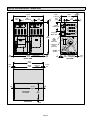
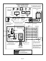
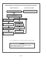
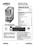
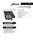
1
INSTALLATION
INSTRUCTIONS
PRODUCT LITERATURE
2005 Lennox Industries Inc.
Dallas, Texas
G24-200
UPFLOW GAS FURNACE
Direct Spark Ignition
503,613M
8/2005
Supersedes 7/2003
Litho USA
Table of Contents
RETAIN THESE INSTRUCTIONS
FOR FUTURE REFERENCE
G24−200 Unit Dimensions . . . . . . . . . . . . . . . . . . . . . . 2
G24−200 Parts Arrangement . . . . . . . . . . . . . . . . . . . . 4
G24−200 Gas Furnace . . . . . . . . . . . . . . . . . . . . . . . . . 6
Shipping and Packing List . . . . . . . . . . . . . . . . . . . . . . 6
Safety . . . . . . . . . . . . . . . . . . . . . . . . . . . . . . . . . . . . . . . 6
General . . . . . . . . . . . . . . . . . . . . . . . . . . . . . . . . . . . . . . 8
Combustion, Dilution & Ventilation Air . . . . . . . . . . . . 8
Setting Equipment . . . . . . . . . . . . . . . . . . . . . . . . . . . . 11
Return Air Plenum / Filter Box Installation . . . . . . . . 11
Duct System . . . . . . . . . . . . . . . . . . . . . . . . . . . . . . . . . 13
Blower Motor and Drive Installation . . . . . . . . . . . . . 13
Venting . . . . . . . . . . . . . . . . . . . . . . . . . . . . . . . . . . . . . 14
Gas Piping . . . . . . . . . . . . . . . . . . . . . . . . . . . . . . . . . . 25
Electrical . . . . . . . . . . . . . . . . . . . . . . . . . . . . . . . . . . . . 27
Unit Start−up . . . . . . . . . . . . . . . . . . . . . . . . . . . . . . . . . 33
Heating Sequence of Operation . . . . . . . . . . . . . . . . 34
Gas Pressure Adjustment . . . . . . . . . . . . . . . . . . . . . 35
High Altitude Information . . . . . . . . . . . . . . . . . . . . . . 35
Other Unit Adjustments and Operation . . . . . . . . . . . 35
Setting Blower CFM . . . . . . . . . . . . . . . . . . . . . . . . . . 37
Repair Parts List . . . . . . . . . . . . . . . . . . . . . . . . . . . . . 39
G24−200 Start−up & Performance Check List . . . . . 39
Troubleshooting . . . . . . . . . . . . . . . . . . . . . . . . . . . . . . 40
WARNING
FIRE OR EXPLOSION HAZARD.
Failure to follow safety warnings exactly could result in serious injury, death,
or property damage.
WHAT TO DO IF YOU SMELL GAS:
Do not store or use gasoline or other
flammable vapors and liquids in the
vicinity of this or any other appliance.
Installation and service must be performed by a qualified installer, service agency or the gas supplier.
08/05
*2P0805*
Do not try to light any appliance.
Extinguish any open flame.
Do not touch any electrical switch; do not
use any phone in your building.
Leave the building immediately.
Immediately call your gas supplier from a
neighbor’s phone. Follow the gas supplier’s instructions.
If you cannot reach your gas supplier, call
the fire department.
503,613M
*P504613M*
G24−200 Unit Dimensions − inches (mm)
52-1/2
(1334)
VENT
OUTLETS
VENT
OUTLETS
10-1/2
(267)
17
(432)
5/8
(16)
5-1/2
(140)
9 (229)
Either Side
4-1/4 (108)
Either Side
53
(1346)
CONTROL
BOX
SUPPLY
AIR
OPENING
29-1/4
(743)
17
(432)
2
(51)
HEAT
EXCHANGER
AIR
FLOW
GAS
PIPING
INLET
Either Side)
ELECTRICAL
INLET
(Either Side)
BLOWER
MOTOR
7/8
(22)
50-3/4
(1289)
Bottom Return
Air Opening
7/8
(22)
FRONT VIEW
50-3/8
(1280)
1
(25)
Supply Air
Opening
BACK VIEW
1-1/16
(27)
1
(25)
50-1/2
(1283)
REAR RETURN
AIR OPENING
Bottom Return
26
(660)
Air Opening
SIDE VIEW
52-1/2
(1334)
1-1/16
(27)
1
(25)
27
(686)
1
(25)
Page 2
2-1/4
(57)
G24−200 Filter Box Dimensions − inches (mm)
AIR
FLOW
5
(127)
4-3/4
(121)
AIR
FLOW
1
(25)
26-1/4
(667)
5 (127)
OPENING SAME
BOTH SIDES
32
(813)
1
(25)
*OPTIONAL
FILTER BOX
*NOTE Return air filter box may be
installed at back or bottom of furnace.
SIDE VIEW
1
(25)
50-1/2
(1283)
BACK VIEW
5
(127)
TOP VIEW
4-3/4
(121)
5
(127)
1
(25)
32
(813)
4-3/4
(121)
50-1/2
(1283)
26-1/4
(667)
1
(25)
OPENING SAME
BOTH SIDES
1
(25)
26-1/4
(667)
1
(25)
1
(25) *NOTE Return air filter box may be
installed at back or bottom of furnace.
50-1/2
(1283)
OPENING SAME
BOTH SIDES
FRONT VIEW
32
(813)
Page 3
G24−200 Parts Arrangement
G24−200 HEAT SECTION AND CABINET
* (THIS UNIT CONTAINS TWO HEAT SECTIONS. EACH
HEAT SECTION CONTAINS ONE OF THESE ITEMS.)
CABINET TOP
LIMIT CONTROL*
HEAT EXCHANGER ASSEMBLY*
PRESSURE SWITCH*
LEFT SIDE PANEL
FLEXIBLE CONNECTOR
FLUE BOX GASKET*
PRESSURE SWITCH*
COMBUSTION
AIR BLOWER*
IGNITION CONTROL*
REAR PANEL − TOP
FLUE BOX*
BURNER RETENTION
BRACKET*
FLAME ROLLOUT
SWITCH*
BURNER MTG
BRACKET*
SENSOR*
IGNITOR*
GAS VALVE*
(two-stage)
CONTROL BOX
REAR PANEL − BOTTOM
RIGHT SIDE PANEL
MAKE−UP BOX*
HEATING COMPARTMENT ACCESS
PANEL*
BLOWER COMPARTMENT ACCESS PANEL
CENTER MULLION
Page 4
G24−200 Parts Arrangement Continued
G24−200 BLOWER SECTION
SHAFT
CUT−OFF PLATE
BLOWER HOUSING
BLOWER
PULLEY
DRIVE BELT
(Drive Kit)
MOTOR
(Drive
Kit)
BEARING
WHEEL
MOTOR PULLEY
(Drive Kit)
MOTOR BASE
ADJUSTMENT ARM
BASE ASSEMBLY
MOTOR BASE
VIBRATION ISOLATOR
LOCATING ROD
Page 5
Use only the type of gas approved for use with this furnace.
Refer to unit nameplate.
G24−200 Gas Furnace
The G24−200 upflow gas furnace is for use with natural
gas only.
Each G24−200 requires the installation of a separately ordered drive kit. The available drive kits are listed in tables 10
and 15. Provided in each drive kit is the following: the furnace’s blower motor, its 24 volt control transformer, and (in
non-208/230 volt models) an autotransformer for each of the
furnaces’s induced draft blowers.
Also available for order separately is a filter box kit for rear or
bottom return air applications.
This furnace has two independently controlled heat sections,
each with an input of 100MBH and each operating in a twostage (low heat/high heat) mode. The C17−090/120 cooling
coil has been designed for use with this furnace and can be
connected to either a single condensing unit or to two condensing units. (See C17 coil installation instructions.)
Package 1 of 3 contains:
1 − Assembled unit (vent adapters are factory-installed)
1 − Flexible gas connector
American National Standards Institute, Inc.
11 West 42nd Street
New York, NY 10036
In Canada, installation must conform with current National
Standard of Canada CSA−B149.1 Natural Gas and Propane Installation Codes", local plumbing or waste water
codes and other applicable local codes.
In the U.S.A, vent installations shall be in accordance with
the venting tables provided in this manual and the applicable provisions of local building codes.
In Canada, vent installations shall be in accordance with
the venting tables in the current editions of the CSA B149
codes and the applicable provisions of local building
codes.
Package 2 of 3 contains:
1 − Filter box assembly
Package 3 of 3 contains:
1 − Blower drive kit consisting of:
1 − Blower motor
1 − Motor pulley
1 − Belt
1 or 3 − Transformer(s)
1 − Bag assembly containing wiring parts
1 − Bag assembly containing securing hardware
This furnace is CSA international certified for installation
clearances to combustible material as listed on unit rating
plate and in table 1. Accessibility and service clearances
must take precedence over fire protection clearances.
Check equipment for shipping damage. If you find any
damage, immediately contact the last carrier.
Safety
WARNING
Improper installation, adjustment, alteration, service
or maintenance can cause property damage, personal injury or loss of life. Installation and service must
be performed by a qualified installer, service agency
or the gas supplier.
As with any mechanical equipment, personal injury
can result from contact with sharp sheet metal
edges. Be careful when you handle this equipment.
In the USA, installation of Lennox gas central furnaces
must conform with local building codes. In the absence of
local codes, units must be installed in accordance with the
current National Fuel Gas Code (ANSI−Z223.1/NFPA54).
The National Fuel Gas Code is available from:
Adequate clearance must be made around the air openings into the vestibule area. Provisions must be made for
proper operation and for combustion air and ventilation air
supply according to the current National Fuel Gas Code or
CSA-B149 standards.
Shipping and Packing List
CAUTION
Lennox G24−200 units are CSA international certified to
ANSI Z21.47 and CSA 2.3 standard.
TABLE 1
INSTALLATION CLEARANCES INCHES (mm)
VENT CONNECTOR TYPE
CLEARANCE
TYPE C
TYPE B1
TOP
1 (25)
1 (25)
FRONT*
3 (76)
3 (76)
BACK
0
0
SIDES
0
0
VENT
6 (152)
1 (25)
FLOOR
0**
0**
* Front clearance must be 24 inches (610mm) minimum for
service access.
** For installation on combustible floors, appliance shall not be
installed directly on carpeting, tile, or other combustible material other than wood flooring.
Maintain adequate clearance for filter access. See section
on Return Air Plenum/Filter Box Installation."
Page 6
For installation in a residential garage, the furnace must be
installed so that the burner(s) and the ignition source are located no less than 18 inches (457 mm) above the floor. The
furnace must be located or protected to avoid physical damage by vehicles. When a furnace is installed in a public garage,
hangar, or other building that has a hazardous atmosphere,
the furnace must be installed according to recommended
good practice requirements and current National Fuel Gas
Code or CSA B149.1 standard.
The furnace must be adjusted to obtain a temperature rise
range and within the allowable external static pressure on
furnaces with a duct system as listed on unit nameplate.
Installation in parking structures must be in accordance
with the Standard for Parking Structures (ANSI/NFPA No.
88A−1991). Installation in repair garages must be in accordance with the Standard for Repair Garages (ANSI/NFPA
No. 88B−1991).
The G24−200 furnace must be installed so that electrical
components are protected from water.
When the furnace is used with cooling units, it shall be
installed in parallel with, or on the upstream side of, cooling
units to avoid condensation in the heating compartment.
With a parallel flow arrangement, a damper (or other means
to control the flow of air) must adequately prevent chilled air
from entering the furnace. If the damper is manually operated, it must be equipped to prevent operation of either the
heating or the cooling unit, unless it is in the full HEAT" or
COOL" setting.
When installed, the furnace must be electrically
grounded according to local codes. In addition, in the
United States, installation must conform with the current
National Electric Code, ANSI/NFPA No. 70. The National
Electric Code (ANSI/NFPA No. 70) is available from the
following address:
National Fire Protection Association
1 Battery March Park
Quincy, MA 02269
In Canada, all electrical wiring and grounding for the unit
must be installed according to the current regulations of the
Canadian Electrical Code Part I (CSA Standard C22.1)
and/or local codes.
Never test for gas leaks with an open flame. Check all connections with a commercially available soap solution made
specifically for leak detection.
NOTE − Furnace must be adjusted to obtain a temperature rise (high and low fire) within the range(s) specified
on the unit nameplate. Failure to do so may cause erratic
limit operation.
Field wiring connection must meet or exceed specifications
of type T wire and withstand a maximum temperature rise
of 180°F (82°C).
When the furnace is installed so that supply ducts carry air
circulated by the furnace to areas outside of the space containing the furnace, return air shall be handled by a duct(s)
sealed to the furnace casing and terminating outside space
containing furnace.
NOTE − This furnace is designed for a minimum continuous return air temperature of 60°F (16°C) or an intermittent operation down to 55°F (13°C) dry bulb for cases
where a night setback thermostat is used. Return air
temperature must not exceed 85°F (29°C) dry bulb.
Use of this unit as a construction heater or air conditioner
is not recommended during any phase of construction.
Very low return air temperatures, harmful vapors and operation of the unit with clogged or misplaced filters will
damage the unit.
If this unit has been used for heating or cooling of buildings
or structures under construction, the following conditions
must be met or the warranty will be void:
The vent hood must be installed per these installation
instructions.
A room thermostat must control the unit. The use of
fixed jumpers that will provide continuous heating or
cooling is not allowed.
A pre−filter must be installed at the entry to the return air
duct.
The return air duct must be provided and sealed to the
unit.
Return air temperature range between 55°F (13°C)
and 80°F (27°C) must be maintained.
Air filters must be replaced and pre−filters must be removed upon construction completion.
The input rate and temperature rise must be set per the
unit rating plate.
The heat exchanger, components, duct system, air filters and evaporator coil must be thoroughly cleaned
following final construction clean−up.
The unit operating conditions (including airflow, cooling operation, ignition, input rate, temperature rise and
venting) must be verified according to these installation instructions.
NOTE − The Commonwealth of Massachusetts stipulates these additional requirements:
Gas units shall be installed by a licensed plumber
or gas fitter only.
The gas cock must be T handle" type.
The Lennox G24−200 furnace may be installed in alcoves,
closets, basements, garages and utility rooms.
Page 7
This furnace design has not been CSA international certified for installation in mobile homes, recreational vehicles,
or outdoors.
WARNING
The blower access panel must be securely in place
when the blower and burners are operating. Gas
fumes, which could contain carbon monoxide, can
be drawn into living space resulting in personal injury or death.
General
These instructions are intended as a general guide and do
not supersede local codes in any way. Consult authorities
having jurisdiction before installation.
In addition to the requirements indicated previously, the following general recommendations should be considered
when installing the Lennox G24−200 furnace.
The furnace should be placed as close to the center of the
air distribution system as possible. The furnace should also
be located close to the chimney or vent termination point.
Do not install the furnace where drafts might blow directly
into it. This could cause improper combustion and unsafe
operation.
Do not block furnace combustion air openings with clothing, boxes, doors, etc. Combustion air is needed for proper
combustion and safe unit operation.
When the furnace is installed in an attic or other insulated
space, keep insulation away from the furnace.
Combustion, Dilution & Ventilation Air
In the past, there was no problem in bringing in sufficient
outdoor air for combustion. Infiltration provided all the air
that was needed. In today’s homes, tight construction
practices make it necessary to bring in air from outside for
combustion. Take into account that exhaust fans, appliance vents, chimneys, and fireplaces force additional
air that could be used for combustion out of the house. Unless outside air is brought into the house for combustion,
negative pressure (outside pressure is greater than inside
pressure) will build to the point that a downdraft can occur
in the furnace vent pipe or chimney. As a result, combustion gases enter the living space creating a potentially
dangerous situation.
In the absence of local codes concerning air for combustion and ventilation, use the guidelines and procedures in
this section to install G24−200 furnaces to ensure efficient
and safe operation. You must consider combustion air
needs and requirements for exhaust vents and gas piping.
A portion of this information has been reprinted with permission from the National Fuel Gas Code
(ANSI-Z223.1/NFPA54). This reprinted material is not the
complete and official position of the ANSI on the referenced subject, which is represented only by the standard
in its entirety.
In Canada, refer to the standard CSA B149.1 installation
code.
WARNING
Product contains fiberglass wool.
Disturbing the insulation in this product during
installation, maintenance, or repair will expose you
to fiberglass wool. Breathing this may cause lung
cancer. (Fiberglass wool is known to the State of California to cause cancer.)
Fiberglass wool may also cause respiratory, skin,
and eye irritation.
To reduce exposure to this substance or for further
information, consult material safety data sheets
available from address shown below, or contact your
supervisor.
Lennox Industries Inc.
P.O. Box 799900
Dallas, TX 75379−9900 USA
Page 8
CAUTION
Do not install furnace in a corrosive or contaminated
atmosphere. Meet all combustion and ventilation air
requirements, as well as all local codes.
Combustion Air Requirements
infiltration. If the furnace is located in a building of tight
construction with weather stripping and caulking around
the windows and doors, follow the procedures in the air
from outside section.
CAUTION
Insufficient combustion air can cause headaches,
nausea, dizziness or asphyxiation. It will also cause
excess water in the heat exchanger resulting in rusting and premature heat exchanger failure. Excessive
exposure to contaminated combustion air will result
in safety and performance related problems. Avoid
exposure to the following substances in the combustion air supply:
Permanent wave solutions
Chlorinated waxes and cleaners
Chlorine base swimming pool chemicals
Water softening chemicals
De-icing salts or chemicals
Carbon tetrachloride
Halogen type refrigerants
Cleaning solvents (such as perchloroethylene
Printing inks, paint removers, varnishes, etc.
Hydrochloric acid
Cements and glues
Antistatic fabric softeners for clothes dryers
Masonry acid washing materials
Confined Space
A confined space is an area with a volume less than 50 cubic feet (1.42 m3) per 1,000 Btu (.29 kW) per hour of the
combined input rating of all appliances installed in that
space. This definition includes furnace closets or small
equipment rooms.
All gas-fired appliances require air for the combustion process. If sufficient combustion air is not available, the furnace or other appliance will operate inefficiently and
unsafely. Enough air must be provided to meet the needs of
all fuel-burning appliances and appliances such as exhaust fans which force air out of the house. When fireplaces, exhaust fans, or clothes dryers are used at the
same time as the furnace, much more air is required to ensure proper combustion and to prevent a downdraft. Insufficient air causes incomplete combustion which can result
in carbon monoxide.
In addition to providing combustion air, fresh outdoor air
dilutes contaminants in the indoor air. These contaminants may include bleaches, adhesives, detergents, solvents and other contaminants which can corrode furnace
components.
The requirements for providing air for combustion and ventilation depend largely on whether the furnace is installed in
an unconfined or a confined space.
Unconfined Space
An unconfined space is an area such as a basement or
large equipment room with a volume greater than 50 cubic
feet (1.42 m3) per 1,000 Btu (.29 kW) per hour of the combined input rating of all appliances installed in that space.
This space also includes adjacent rooms which are not
separated by a door. Though an area may appear to be unconfined, it might be necessary to bring in outdoor air for
combustion if the structure does not provide enough air by
When the furnace is installed so that supply ducts carry air
circulated by the furnace to areas outside the space containing the furnace, the return air must be handled by ducts
which are sealed to the furnace casing and which terminate
outside the space containing the furnace. This is especially
important when the furnace is mounted on a platform in a
confined space such as a closet or small equipment room.
Even a small leak around the base of the unit at the platform
or at the return air duct connection can cause a potentially
dangerous negative pressure condition. Air for combustion
and ventilation can be brought into the confined space either
from inside the building or from outside.
Air from Inside
If the confined space that houses the furnace adjoins a
space categorized as unconfined, air can be brought in by
providing two permanent openings between the two
spaces. Each opening must have a minimum free area of 1
square inch (645 mm2) per 1,000 Btu (.29 kW) per hour of
total input rating of all gas−fired equipment in the confined
space. Each opening must be at least 100 square inches
(64516 mm2). One opening shall be within 12 inches (305
mm) of the top of the enclosure and one opening within 12
inches (305 mm) of the bottom. See figure 1.
Air from Outside
If air from outside is brought in for combustion and ventilation, the confined space must have two permanent openings. One opening shall be within 12 inches (305 mm) of the
top of the enclosure and one opening within 12 inches (305
mm) of the bottom. These openings must communicate directly or by ducts with the outdoors or spaces (crawl or attic) that freely communicate with the outdoors or indirectly
through vertical ducts. Each opening shall have a minimum
free area of 1 square inch (645 mm2) per 4,000 Btu (1.17
kW) per hour of total input rating of all equipment in the enclosure. See figures 2 and 3. When communicating with
the outdoors through horizontal ducts, each opening shall
have a minimum free area of 1 square inch (645 mm2) per
2,000 Btu (.56 kW) per total input rating of all equipment in
the enclosure. See figure 4.
Page 9
When ducts are used, they shall be of the same cross−sectional area as the free area of the openings to which they
connect. The minimum dimension of rectangular air ducts
shall be no less than 3 inches (75 mm). In calculating free
area, the blocking effect of louvers, grilles, or screens
must be considered. If the design and free area of protective covering is not known for calculating the size opening
required, it may be assumed that wood louvers will have
20 to 25 percent free area and metal louvers and grilles
will have 60 to 75 percent free area. Louvers and grilles
must be fixed in the open position or interlocked with the
equipment so that they are opened automatically during
equipment operation.
EQUIPMENT IN CONFINED SPACE
ALL AIR FROM INSIDE
CHIMNEY
OR GAS
VENT
G24−200
FURNACE
OPENINGS
(To Adjacent
Room)
NOTE−Each opening shall have a free area of at least one square
inch (645 mm2) per 1,000 Btu (.29 kW) per hour of the total input rating of all equipment in the enclosure, but not less than 100 square
inches (64516 mm 2).
FIGURE 1
EQUIPMENT IN CONFINED SPACE ALL AIR FROM OUTSIDE
(Inlet Air from Crawl Space and Outlet Air to Ventilated Attic)
CHIMNEY OR
GAS VENT
VENTILATION LOUVERS
(Each end of attic)
OUTLET
AIR
G24−200
FURNACE
INLET
AIR
VENTILATION
LOUVERS
(For unheated crawl space)
NOTE−The inlet and outlet air openings shall each have a free area of at least one square inch (645 mm2)
per 4,000 Btu (1.17 kW) per hour of the total input rating of all equipment in the enclosure.
FIGURE 2
Page 10
EQUIPMENT IN CONFINED SPACE
ALL AIR FROM OUTSIDE
(All Air Through Ventilated Attic)
CHIMNEY
OR GAS
VENT
VENTILATION LOUVERS
(Each end of attic)
OUTLET
AIR
G24−200
FURNACE
INLET AIR
(Ends 12 in.
above bottom)
NOTE−The inlet and outlet air openings shall each have a
free area of at least one square inch (645 mm2) per 4,000
Btu (1.17 kW) per hour of the total input rating of all equipment in the enclosure.
FIGURE 3
EQUIPMENT IN CONFINED SPACE
(ALL AIR FROM OUTSIDE)
Setting Equipment
WARNING
Do not install the furnace on its front or its back. Doing so will adversely affect the operation of the safety
control devices, which could result in personal injury or death.
The Lennox G24−200 upflow gas furnace can be
installed with rear or bottom return air. If unit is installed
on a platform with bottom return air, furnace/filter box must
be sealed airtight at the platform to ensure proper and safe
operation.
Select a location that allows for required clearances listed
on unit rating plate. Also consider gas supply connections,
electrical supply, vent connection, installation and service
clearances [24 inches (610mm) at unit front] and filter accessibility.
The furnace must be leveled using shims or leveling bolts
(field provided). The corner gussets provided in the furnace
base will accept leveling bolts.
Return Air Plenum / Filter Box Installation
Return air openings are provided at rear and in bottom of
unit. A return air closure panel is shipped secured to the
rear opening.
A − Bottom Return Air (Refer to figure 5)
1 − Determine the location of the furnace/filter box.
CHIMNEY
OR GAS
VENT
2 − Cut 50-5/8 x 26-1/8 (128.6cm x 66.4cm) opening in the
return air platform.
OUTLET AIR
G24−200
FURNACE
3 − Fabricate the return air plenum with right angle flanges
and insert into the floor opening.
4 − Remove filter box access door and filters.
INLET AIR
NOTE−Each air duct opening shall have a free area of at least
one square inch (645 mm 2) per 2,000 Btu (.59 kW) per hour of
the total input rating of all equipment in the enclosure. If the
equipment room is located against an outside wall and the air
openings communicate directly with the outdoors, each opening shall have a free area of at least one square inch (645 mm2)
per 4,000 Btu (1.17 kW) per hour of the total input rating of all
other equipment in the enclosure.
FIGURE 4
5 − Apply adhesive-backed foam tape to the bottom of the
filter box all around the opening. Position the filter box
over the return air plenum. Fasten as required using
self-tapping screws provided.
Make sure there is an air tight seal between the
platform/return air plenum and filter box.
6 − Apply adhesive-backed foam to the top of the filter box
all around the opening. Place furnace over the filter box
with sides and rear of furnace and filter box flush. Fasten as required.
Make sure there is an air tight seal between the furnace and the filter box.
Page 11
7 − Install the filters and the filter access door.
BOTTOM RETURN AIR FILTER BOX INSTALLATION
UNIT
2-3/4
(70)
29-1/4 (743)
Furnace
27-1/4 (692)
Opening
1
(25)
4-3/4
(121)
ÎÎÎÎ
ÎÎÎÎ
ÎÎÎÎ
26-1/4 (667)
Filter Box
Opening
AIR
FLOW
ADHESIVEBACKED
FOAM TAPE
26-1/8 (664) x 50-5/8 (1286)
RETURN AIR PLENUM
1
(25)
FILTER
BOX
ÎÎ
ÎÎ
ÎÎ
PLATFORM
Floor Opening
INCHES (mm)
SIDE VIEW
FIGURE 5
WARNING
Improper installation of the furnace can result in personal injury or death. Combustion and flue products
must never be allowed to enter the return air system
or the living space. Use screws and joint tape to seal
the return air system to the furnace.
In platform installations with bottom return air, the
furnace should be sealed airtight to the return air plenum. A door must never be used as a portion of the
return air duct system. The base must provide a
stable support and an airtight seal to the furnace. Allow absolutely no sagging, cracks, gaps, etc.
The return and supply air duct systems must never
be connected to or from other heating devices such
as a fireplace or stove, etc. Fire, explosion, carbon
monoxide poisoning, personal injury and/or property damage could result.
Page 12
B − Rear Return Air (Refer to figure 6)
Duct System
REAR RETURN AIR FILTER BOX INSTALLATION
Size and install supply and return air duct system using industry-approved standards that result in a quiet and lowstatic system with uniform air distribution.
ADHESIVE-BACKED
FOAM TAPE
(Apply to filter box)
UNIT
Supply Air Plenum
Furnaces installed without a cooling coil require the installation of a removable access panel in the supply air duct. The
access panel should be large enough to permit inspection (either by smoke or reflected light) of the heat exchanger for
leaks after installation. The furnace access panel must always be in place when the furnace is operating and it must
not allow leaks into the supply air duct system.
FILTER
ACCESS
PANEL
In applications requiring air conditioning, see installation
instructions provided with C17-090/120 evaporator coil for
supply air plenum size and connection.
Return Air Plenum
Return air must not be drawn from a room where this
furnace, or any other gas appliance (i.e., a water heater), is installed. When return air is drawn from a room, a
negative pressure is created in the room. If a gas appliance is operating in a room with negative pressure, the
flue products can be pulled back down the vent pipe and
into the room. This reverse flow of the flue gas may result
in incomplete combustion and the formation of carbon
monoxide gas. This toxic gas might then be distributed
throughout the house by the furnace duct system.
RETURN AIR
FILTER BOX
FILTER
ACCESS
PANEL
FOUR FILTERS (Filters may be
also installed through top of frame)
REPOSITION REAR PANEL WITH FLANGES AS SHOWN.
(Seal air-tight with adhesive-backed foam tape.)
FIGURE 6
1 − Determine the location of the furnace/filter box.
NOTE − Filter box can be installed with right or left side
filter access or top-rear filter access. Allow enough
room when positioning the furnace for filter access.
2 − Remove the bottom-rear panel from the furnace and
re-install on the bottom of the furnace as shown. Seal
air-tight with adhesive-backed foam tape.
3 − Apply adhesive-backed foam tape to the filter box (side
facing furnace) all around the opening. Refer to figure 6.
4 − Position the filter box over the furnace return air opening. The top of the filter box should be in the up" position and the filter box and the furnace edges flush at the
sides and bottom.
5 − Fasten using self-drilling self-tapping screws provided
with the filter box. Use the frame clearance holes as a
guide.
Size and install return air plenum as indicated in previous
section.
Blower Motor / Drive Installation
A − Motor Installation
Refer to figure 7.
1 − Check the box on the rating plate to indicate which of
the drive kits are being installed.
2 − Secure the blower motor to the motor base with the
hardware provided.
3 − Slide the motor pulley onto the motor shaft and align
with the blower pulley.
4 − Install the belt.
5 − Refer to Setting Blower CFM Section" to determine
blower RPM setting and the following section for adjusting belt tension.
6 − Install the four filters and the filter access door.
7 − Size the return air plenum to fit the filter box and then
seal the joint air tight.
Page 13
Example: Deflection distance of a 400mm span would
be 6mm.
TYPICAL MOTOR/DRIVE INSTALLATION
3 − Measure the belt deflection force. For a used belt, the
deflection force should be 5 lbs. (35kPa). A new belt
deflection force should be 7 lbs. (48kPa).
MOTOR
MOTOR PULLEY
A force below these values indicates an under-tensioned belt. A force above these values indicates an
over-tensioned belt.
MOTOR SECURING
HARDWARE
MEASURE BELT TENSION
MOTOR BASE
BELT TENSION ADJUSTING HARDWARE
PULLEY ALIGNMENT
FORCE
BLOWER
PULLEY
DEFLECTION 1/64 INCH PER INCH OF SPAN
OR 1.5 mm PER 100 mm OF SPAN
FIGURE 8
Venting
MOTOR
PULLEY
A vent adapter is factory-installed on each of the combustion air blower outlets. Modification of, or removal of the
adapter(s) will cause unsafe unit operation and will
void CSA unit certification. The vent adapter does not require insulation.
FIGURE 7
B − Blower Belt Adjustment
Maximum life and wear can be obtained from belts only if
the proper pulley alignment and belt tension are maintained. Tension new belts after a 24 to 48 hour period of operation. This will allow the belt to stretch and seat in the
grooves.
1 − Loosen belt adjusting hardware. See figure 7.
2 − To increase belt tension −
Move the motor base away from the blower housing.
To loosen belt tension −
Move the motor toward the blower housing.
3 − Tighten the belt adjusting hardware.
C − Check Belt Tension
Over-tensioning a belt shortens belt and bearing life.
Check belt tension as follows:
1 − Measure span length X. See figure 8.
2 − Apply perpendicular force to the center of span (X)
with enough pressure to deflect belt 1/64 inch for every inch of span length or 1.5mm per 100mm of span
length.
Example: Deflection distance of a 40 inch span would
be 40/64 inch or 5/8 inch.
The G24−200 units are classified as fan assisted Category I
type furnaces when vertically vented according to the latest
edition of ANSI Z21.47 Gas-fired Central Furnace Standard
in the USA and the current standard CSA 2.3 Gas-fired Central Furnace in Canada. The definition of a fan assisted furnace is an appliance equipped with an integral mechanical
means to either draw or force products of combustion
through the combustion chamber and/or heat exchanger.
NOTE − Use these instructions as a guide. They do not supersede local codes.
The vent sizing tables in this manual have been extracted
from the Current edition of the National Fuel Gas Code
(NFPA 54 / ANSI Z223.1) and are provided as a guide for
proper vent installation. Proper application, termination,
construction and location of vents must conform to local
codes having jurisdiction. In the absence of local codes,
the NFGC serves as the defining document in the U.S.A.,
while the CSA−B149 codes serve as the defining documents in Canada.
Refer to the tables and the venting information contained in
these instructions to properly size and install the venting
system.
Install the first vent connector elbow a minimum of 6 in.
(152mm) from the furnace vent outlet.
Page 14
Venting Using a Masonry Chimney
The following additional requirements apply when a lined
masonry chimney is used to vent a G24−200 furnace:
A type B1 vent or masonry chimney liner shall terminate above
the roof surface with a listed cap or a listed roof assembly according to the terms of their respective listings and the vent
manufacturer’s instructions.
Masonry chimneys used to vent Category I central furnaces must be either tile-lined or lined with a listed metal
lining system or dedicated gas vent. Unlined masonry
chimneys are prohibited. See figures 9 and 10 for common
venting.
Do not install a manual damper, barometric draft regulator, or flue restrictor between the furnace and the chimney.
A Category I appliance must never be connected to a chimney that is servicing a solid−fuel appliance. If a fireplace
chimney flue is used to vent this appliance, the fireplace
opening must be permanently sealed.
A fan−assisted furnace may be commonly vented into an
existing lined masonry chimney if the following conditions
are met:
1 − The chimney is currently serving at least one drafthood
equipped appliance.
2 − The vent connectors and chimney are sized according
to the provided venting tables for the USA, and the appropriate venting tables in the standards of CSA
B149.1 of the Natural Gas and Propane Installation
Code in Canada.
IMPORTANT
SINGLE appliance venting of a fan-assisted furnace
into a tile-lined masonry chimney (interior or outside
wall) is PROHIBITED. The chimney must first be lined
with either type B1 vent or an insulated single wall
flexible vent lining system, sized according to the
provided venting tables.
If type B1 double-wall vent is used inside a chimney, no other appliance can be vented into the chimney. Outer wall of
type B1 vent pipe must not be exposed to flue products.
Insulation for the flexible vent pipe must be an encapsulated fiberglass sleeve recommended by the flexible vent
pipe manufacturer. See figure 9.
The space between the liner and the chimney wall
should NOT be insulated with puffed mica or any other
loose granular insulating material.
If B1 vent or an insulated flexible vent pipe cannot be used
as liners, the chimney must be rebuilt to accommodate one
of these methods or some alternate approved method
must be found to vent the appliance.
When inspection reveals that an existing chimney is not
safe for the intended purpose, it shall be rebuilt to conform
to nationally recognized standards, lined or relined with
suitable materials or replaced with a gas vent or chimney
suitable for venting G24−200 units. The chimney passageway must be checked periodically to ensure that it is clear
and free of obstructions.
COMMON VENTING USING METAL−LINED MASONRY CHIMNEY
NOTE 1 − Refer to the provided venting tables
for installations in the USA and the venting
tables in CSA−B149.1 for installations Canada.
NOTE 2 − Either single-walled or double-walled
vent connector may be used. Refer to the capacity requirements shown in the provided
venting tables for installations in USA and the
venting tables in current CSA−B149.1 for
installations in Canada.
5 FT.
(1.5m)
MIN.
MAX. LENGTH − SEE
NOTE 1 BELOW.
MIN. LENGTH − AS SHORT
AS PRACTICAL
SEALED
EXTERIOR CHIMNEY WITH
B1" VENT OR INSULATED
FLEXIBLE VENT PIPE
PERMANENTLY
SEALED FIREPLACE OPENING
VENT
CONNECTOR
SEE NOTE 2
G24−200
FIGURE 9
Page 15
JOIN HEAT
SECTIONS
WITH A ’TEE−Y’
COMMON VENTING USING TILE−LINED INTERIOR MASONRY CHIMNEY AND COMBINED VENT CONNECTOR
NOTE 1 − Refer to provided venting tables
for installations in the USA and the venting tables in current CSA−B149.1 for
installations in Canada.
MIN. LENGTH = AS SHORT AS PRACTICAL.
FOR MAX. LENGTH SEE NOTE 1
INTERIOR TILE−LINED
MASONRY CHIMNEY
JOIN HEAT SECTIONS
WITH A ’TEE−Y’
VENT
CONNECTOR
SEE NOTE 2
Note 2 − Either single-walled or double-walled vent
connector may be used. Refer to the capacity requirements as shown in the provided venting tables
for installations in USA and the venting tables in current CSA−B149.1 for installations in Canada.
NOTE − The chimney must be
properly sized per provided venting tables and lined with a listed
metal lining system.
PERMANENTLY SEALED
FIREPLACE OPENING
G24−200
FIGURE 10
General Venting Requirements
All G24−200 furnaces must be vented according to these
instructions.
1 − Vent diameter recommendations and maximum allowable piping runs are found in the provided venting
tables for the USA, and the appropriate venting tables
in the standards of CSA B149.1 of the Natural Gas and
Propane Installation Code for Canada.
2 − In no case should the vent or vent connector diameter
be less than the diameter specified in the provided
venting tables for the USA, and the appropriate venting tables in the standards of CSA B149.1 of the Natural Gas and Propane Installation Code for Canada.
3 − Single Appliance Vent − If the vertical vent or tile-lined
chimney has a larger diameter or flow area than the
vent connector, use the vertical vent diameter to determine the minimum vent capacity and the vent
connector diameter to determine the maximum
vent capacity. The flow area of the vertical vent, however, shall not exceed 7 times the flow area of the
listed appliance categorized vent area, drafthood outlet area or flue collar area unless designed according
to approved engineering methods.
4 − Multiple Appliance Vents − The flow area of the largest
section of vertical vent or chimney shall not exceed 7
times the smallest listed appliance categorized vent
area, flue collar area or drafthood outlet area unless
designed according to engineering methods.
5 − The entire length of single wall metal vent connector
shall be readily accessible for inspection, cleaning,
and replacement.
6 − Single appliance venting configurations with zero lateral lengths, see tables 3 and 4, are assumed to have
no elbows in the vent system. For all other vent configurations, the vent system is assumed to have two 90
elbows. For each additional 90 elbow or equivalent
(for example two 45 elbows equal one 90 elbow) beyond two, the maximum capacity listed in the venting
table should be reduced by 10 percent (0.90 x maximum listed capacity).
7 − The common venting tables 5, 6, 7, and 8 were generated using a maximum horizontal vent connector
length of 1-1/2 feet (18 inches) for each inch of connector diameter as follows:
TABLE 2
Connector
Diameter
inches (mm)
Maximum Horizontal
Connector Length
feet (m)
3 (76)
4 (102)
5 (127)
6 (152)
7 (178)
4−1/2 (1.37)
6 (1.83)
7−1/2 (2.29)
9 (2.74)
10−1/2 (3.20)
8 − If the common vertical vent is offset, the maximum
common vent capacity listed in the common venting
tables should be reduced by 20%, the equivalent of
two 90 elbows (0.80 x maximum common vent capacity). The horizontal length of the offset shall not exceed 1-1/2 feet (.46 m) for each inch (25 mm) of
common vent diameter.
9 − The vent pipe should be as short as possible with
the least number of elbows and angles to do the job.
The vent connector should be routed to the vent using
the shortest possible route.
Page 16
10− A vent connector shall be supported without any dips
or sags and shall slope a minimum of 1/4inch (6.4 mm)
per linear foot (305 mm) of connector, back toward the
appliance. See local and national installation codes for
support intervals and methods. National installation
code in the U.S.A is current edition of National fuel Gas
Code (ANSI−Z223.1/NFPA54). National installation
codes in Canada are current editions of CSA−B149
codes.
11− Vent connectors shall be firmly attached to furnace flue
collars by sheet metal screws or other approved
means, except vent connectors of listed Type B vent
material which shall be assembled according to the
manufacturer’s instructions. Joints between sections
of single wall connector piping shall be fastened by
sheet metal screws or other approved means.
12− When the vent connector used for Category I appliances must be located in or pass through a crawl
space or other areas which may be cold, that portion
of the vent connector shall be constructed of listed
double−wall Type B vent material or material having
equivalent insulation qualities.
13− All venting pipe passing through floors, walls, and ceilings must be installed with the listed clearance to combustible materials and be fire stopped according to
local codes. In absence of local codes, refer to NFGC
(Z223.1/NFPA54).
14− No portion of the venting system can extend into, or pass
through any circulation air duct or plenum.
15− Vent connectors serving Category I appliances shall
not be connected to any portion of mechanical draft
systems operating under positive pressure such as
Category III or IV venting systems.
16− If vent connectors are combined prior to entering the
common vent, the maximum common vent capacity
listed in the common venting tables must be reduced by
10 percent, the equivalent of one 90 elbow (0.90 x
maximum common vent capacity).
17− The common vent diameter must always be at least as
large as the largest vent connector diameter.
18− In no case, shall the vent connector be sized more than
two consecutive table size diameters over the size of
the flue collar outlet.
19− Do not install a manual damper, barometric draft regulator or flue restrictor between the furnace and the
chimney.
20− When connecting this appliance to an existing dedicated
or common venting system, the venting system must be
inspected for signs of corrosion and general condition.
The sizing of the vent system must be reviewed and
must conform to these instructions and the provided
venting tables for the USA, and the appropriate venting
tables in the standards of CSA B149.1 of the Natural
Gas and Propane Installation Code for Canada. If the existing system is in conflict with these requirements, the
venting system must be resized.
Page 17
TABLE 3
CAPACITY OF TYPE B DOUBLE-WALL VENTS WITH TYPE B DOUBLE-WALL CONNECTORS
SERVING A SINGLE CATEGORY I APPLIANCE
Vent and Connector Diameter − D (inches)
Height
H
(feet)
6
8
10
15
20
30
Lateral
L
(feet)
3 Inch
4 Inch
5 Inch
6 Inch
Appliance Input Rating in Thousands of Btu Per Hour
MIN
MAX
MIN
MAX
MIN
MAX
MIN
MAX
0
0
78
0
152
0
251
0
375
2
13
51
18
97
27
157
32
232
4
21
49
30
94
39
153
50
227
6
25
46
36
91
47
149
59
223
0
0
84
0
165
0
276
0
415
2
12
57
16
109
25
178
28
263
5
23
53
32
103
42
171
53
255
8
28
49
39
98
51
164
64
247
0
0
88
0
175
0
295
0
447
2
12
61
17
118
23
194
26
289
5
23
57
32
113
41
187
52
280
10
30
51
41
104
54
176
67
267
0
0
94
0
191
0
327
0
502
2
11
69
15
136
20
226
22
339
5
22
65
30
130
39
219
49
330
10
29
59
40
121
51
206
64
315
15
35
53
48
112
61
195
76
301
0
0
97
0
202
0
349
0
540
2
10
75
14
149
18
250
20
377
5
21
71
29
143
38
242
47
367
10
28
64
38
133
50
229
62
351
15
34
58
46
124
59
217
73
337
20
48
52
55
116
69
206
84
322
0
0
100
0
213
0
374
0
587
2
9
81
13
166
14
283
18
432
5
21
77
28
160
36
275
45
421
10
27
70
37
150
48
262
59
405
15
33
64
44
141
57
249
70
389
20
56
58
53
132
66
237
80
374
30
NR
NR
73
113
88
214
104
346
NOTE − Single appliance venting configurations with zero lateral lengths are assumed to have no elbows in the vent system. For all other vent configurations, the vent
system is assumed to have two 90 elbows. For each additional 90 elbow or equivalent (for example two 45 elbows equal one 90 elbow) beyond two, the maximum
capacity listed in the venting table should be reduced by 10 percent (0.90 x maximum listed capacity).
Page 18
TABLE 4
CAPACITY OF TYPE B DOUBLE-WALL VENTS WITH SINGLE-WALL METAL CONNECTORS
SERVING A SINGLE CATEGORY I APPLIANCE
Vent and Connector Diameter − D (inches)
Height
H
(feet)
6
8
10
15
20
30
Lateral
L
(feet)
3 Inch
4 Inch
5 Inch
6 Inch
Appliance Input Rating in Thousands of Btu Per Hour
MIN
MAX
MIN
MAX
MIN
MAX
MIN
MAX
0
38
77
59
151
85
249
126
373
2
39
51
60
96
85
156
123
231
4
NR
NR
74
92
102
152
146
225
6
NR
NR
83
89
114
147
163
220
0
37
83
58
164
83
273
123
412
2
39
56
59
108
83
176
121
261
5
NR
NR
77
102
107
168
151
252
8
NR
NR
90
95
122
161
175
243
0
37
87
57
174
82
293
120
444
2
39
61
59
117
82
193
119
287
5
52
56
76
111
105
185
148
277
10
NR
NR
97
100
132
171
188
261
0
36
93
56
190
80
325
116
499
2
38
69
57
136
80
225
115
337
5
51
63
75
128
102
216
144
326
10
NR
NR
95
116
128
201
182
308
15
NR
NR
NR
NR
158
186
220
290
0
35
96
54
200
78
346
114
537
2
37
74
56
148
78
248
113
375
5
50
68
73
140
100
239
141
363
10
NR
NR
93
129
125
223
177
344
15
NR
NR
NR
NR
155
208
216
325
20
NR
NR
NR
NR
186
192
254
306
0
34
99
53
211
76
372
110
584
2
37
80
55
164
76
281
109
429
5
49
74
72
157
98
271
136
417
10
NR
NR
91
144
122
255
171
397
15
NR
NR
115
131
151
239
208
377
20
NR
NR
NR
NR
181
223
246
357
30
NR
NR
NR
NR
NR
NR
NR
NR
NOTE − Single appliance venting configurations with zero lateral lengths are assumed to have no elbows in the vent system. For all other vent configurations, the vent
system is assumed to have two 90 elbows. For each additional 90 elbow or equivalent (for example two 45 elbows equal one 90 elbow) beyond two, the maximum
capacity listed in the venting table should be reduced by 10 percent (0.90 x maximum listed capacity).
Page 19
TABLE 5
CAPACITY OF TYPE B DOUBLE-WALL VENTS WITH TYPE B DOUBLE-WALL CONNECTORS
SERVING TWO OR MORE CATEGORY I APPLIANCES
VENT CONNECTOR CAPACITY
Vent
Height
H
(feet)
6
8
10
15
20
30
Vent and Connector Diameter − D (inches)
Connector
Rise
R
(feet)
4 Inch
5 Inch
6 Inch
7 Inch
Appliance Input Rating in Thousands of Btu Per Hour
MIN
MAX
MIN
MAX
MIN
MAX
MIN
MAX
1
35
66
46
106
58
164
77
225
2
37
75
48
121
60
183
79
253
3
38
81
49
132
62
199
82
275
1
35
72
49
114
64
176
84
243
2
36
80
51
128
66
195
86
269
3
37
87
53
139
67
210
88
290
1
34
78
49
123
65
189
89
257
2
36
86
51
136
67
206
91
282
3
37
92
52
146
69
220
94
303
1
33
89
47
142
64
220
88
298
2
35
96
49
153
66
235
91
320
3
36
102
51
163
68
248
93
339
1
33
99
46
157
62
246
86
334
2
34
105
48
167
64
259
89
354
3
35
110
50
176
66
271
91
371
1
31
113
45
181
60
288
83
391
2
33
118
47
190
62
299
85
408
3
34
123
48
198
64
309
88
423
TABLE 6
CAPACITY OF TYPE B DOUBLE-WALL VENTS WITH TYPE B DOUBLE-WALL CONNECTORS
SERVING TWO OR MORE CATEGORY I APPLIANCES
COMMON VENT CAPACITY
Vent
Height
H
(feet)
Common Vent Diameter − D (inches)
4 Inch
5 Inch
6 Inch
7 Inch
Appliance Input Rating in Thousands of Btu Per Hour
FAN + FAN
FAN + NAT
FAN + FAN
FAN + NAT
FAN + FAN
FAN + NAT
FAN + FAN
FAN + NAT
6
92
81
140
116
204
161
309
248
8
101
90
155
129
224
178
339
275
10
110
97
169
141
243
194
367
299
15
125
112
195
164
283
228
427
352
20
136
123
215
183
314
255
475
394
30
152
138
244
210
361
297
547
459
Page 20
TABLE 7
CAPACITY OF TYPE B DOUBLE-WALL VENT WITH SINGLE-WALL METAL CONNECTORS
SERVING TWO OR MORE CATEGORY I APPLIANCES − VENT CONNECTOR CAPACITY
Vent
Height
H
(feet)
6
15
30
Vent and Connector Diameter − D (inches)
Connector
Rise
R
(feet)
4 Inch
5 Inch
6 Inch
7 Inch
Appliance Input Rating in Thousands of Btu Per Hour
MIN
MAX
MIN
MAX
MIN
MAX
MIN
MAX
1
NR
NR
NR
NR
NR
NR
207
223
2
NR
NR
NR
NR
168
182
215
251
3
NR
NR
121
131
174
198
222
273
1
79
87
116
138
177
214
238
291
2
83
94
121
150
185
230
246
314
3
87
100
127
160
193
243
255
333
1
77
110
113
175
169
278
226
380
2
81
115
117
185
177
290
236
397
3
85
119
122
193
185
300
244
412
TABLE 8
CAPACITY OF TYPE B DOUBLE-WALL VENTS WITH SINGLE-WALL METAL CONNECTORS
SERVING TWO OR MORE CATEGORY I APPLIANCES − COMMON VENT CAPACITY
Vent
Height
H
(feet)
Common Vent Diameter − D (inches)
4 Inch
5 Inch
6 Inch
7 Inch
Appliance Input Rating in Thousands of Btu Per Hour
FAN + FAN
FAN + NAT
FAN + FAN
FAN + NAT
FAN + FAN
FAN + NAT
FAN + FAN
FAN + NAT
6
89
78
8
98
87
136
113
200
158
304
244
151
126
218
173
331
10
106
269
94
163
137
237
189
357
292
15
20
121
108
189
159
275
221
416
343
131
118
208
177
305
247
463
30
383
145
132
236
202
350
286
533
446
Removal of the Furnace from Common Vent
In the event that an existing furnace is removed from a
venting system commonly run with separate gas appliances, the venting system is likely to be too large to properly vent the remaining attached appliances. The following
test should be conducted while each appliance in operation
and the other appliances not in operation remain connected to the common venting system. If the venting system has been installed improperly, the system must be
corrected as indicated in the general venting requirements
section.
1 − Seal any unused openings in the common venting
system.
2 − Visually inspect the venting system for proper size and
horizontal pitch. Determine there is no blockage or restriction, leakage, corrosion, or other deficiencies which
could cause an unsafe condition.
3 − To the extent that it is practical, close all building doors
and windows and all doors between the space in which
the appliances remaining connected to the common
venting system are located and other spaces of the building. Turn on clothes dryers and any appliances not connected to the common venting system. Turn on any
exhaust fans, such as range hoods and bathroom ex-
hausts, so they will operate at maximum speed. Do not
operate a summer exhaust fan. Close fireplace dampers.
4 − Follow the lighting instructions. Place the appliance being
inspected in operation. Adjust thermostat so appliance
will operate continuously.
5 − Test for spillage of the flue gases at the draft hood relief
opening after 5 minutes of main burner operation. Use
the flame of a match or candle, or smoke from a cigarette,
cigar or pipe.
6 − After determining that each appliance remaining connected to the common venting system properly vents
when tested as indicated instep 3, return doors, windows,
exhaust fans, fireplace dampers and any other gas−burning appliance to their previous condition of use.
7 − If improper venting is observed during any of the
above tests, the common venting system must be corrected. The common venting system should be resized to approach the minimum size as determined by
using the appropriate tables in appendix G in the current standards of the National Fuel Gas Code ANSI
Z223.1 /NFPA54 in the USA, and the appropriate
Category 1 Natural Gas appliances venting sizing
tables in the current standards of the CSA−B149.1
Natural Gas Installation Code in Canada.
Page 21
Testing for Proper Venting and Sufficient Combustion Air
(Non−Direct Vent Applications Only)
WARNING
CARBON MONOXIDE POISONING HAZARD!
Failure to follow the steps outlined below for each
appliance connected to the venting system being
placed into operation could result in carbon monoxide poisoning or death.
The following steps shall be followed for each appliance connected to the venting system being
placed into operation, while all other appliances connected to the venting system are not in operation.
After the furnace has been started, the following test
should be conducted to ensure proper venting and sufficient combustion air has been provided to the furnace, as
well as to other gas-fired appliances which are separately
vented. The test should be conducted while all appliances
(both in operation and those not in operation) are connected to the venting system being tested.
1 − Seal any unused openings in the venting system.
2 − Visually inspect the venting system for proper size and
horizontal pitch. Determine there is no blockage or restriction, leakage, corrosion, or other deficiencies
which could cause an unsafe condition.
3 − To the extent that it is practical, close all building doors
and windows and all doors between the space in which
the appliances connected to the venting system are located and other spaces of the building.
4 − Close fireplace dampers.
5 − Turn on clothes dryers and any appliances not connected to the venting system. Turn on any exhaust
fans, such as range hoods and bathroom exhausts, so
they will operate at maximum speed. Do not operate a
summer exhaust fan.
6 − Follow the lighting instruction to place the appliance
being inspected into operation. Adjust thermostat so
appliance will operate continuously.
7 − Test for spillage of flue gases at the draft hood relief
opening after 5 minutes of main burner operation. Use
the flame of match or candle, or smoke from a cigarette, cigar.
8 − If improper venting is observed during any of the
above tests, the venting system must be corrected or
sufficient combustion/make-up air must be provided.
The venting system should be re-sized to approach
the minimum size as determined by using the appropriate tables in appendix G in the current standards of the National Fuel Gas Code
ANSI−Z223.1/NPFA 54 in the U.S.A., and the appropriate Natural Gas and Propane appliances venting sizing tables in the current standard of the
CSA−B149.1 Natural Gas and Propane Installation
Code in Canada.
9 − After determining that each appliance remaining
connected to the common venting system properly
vents when tested as indicated in step 3, return
doors, windows, exhaust fans, fireplace dampers
and any other gas-burning appliance to their previous condition of use.
General Guidelines for Vent Terminations for Non-Direct
Vent Installations.
In Non-Direct Vent applications, combustion air is taken
from indoors and the flue gases are discharged to the outdoors. The furnace is then classified as a non-direct vent,
Category IV gas furnace. In Non-Direct Vent applications,
the vent termination is limited by local building codes. In
the absence of local codes, refer to the current National
Fuel Gas Code ANSI Z223−1/NFPA 54 in U.S.A., and current standards CSA−B149.1 of the Natural Gas and Propane Installation Codes in Canada for details.
Position termination end according to location given in figure 11. In addition, position termination end so it is free
from any obstructions and above the level of snow accumulation (where applicable). The termination should be at
least 12 inches (305mm) from any opening through which
flue products could enter the building.
Page 22
VENT TERMINATION CLEARANCES
FOR INSTALLATIONS IN THE USA AND CANADA*
− VENT TERMINATION
− AIR INLET OF OTHER APPLIANCE
C
less than
10 ft (3.048M)
D
F
D
E
G
A − Clearance above grade − 12 in. (305mm) minimum.
B − Clearance to window or door −
for vent installations in USA − 48 in. (1219mm) minimum
horizontal and below, 12 in. (305mm) minimum above.
for vent installations in Canada − 12 in. (305mm) minimum
for appliances 100,000 Btuh (30 kW);
36 in. (0.9m) minimum for appliances > 100,000 Btuh (30
kW).
C − Do not position terminations directly under roof eaves.
D − Clearance to electric meters, gas meters, regulators, and
relief equipment −
for vent installations in USA − 48 in (1219mm) minimum.
for vent installations in Canada − see current edition of
CSA B149 Code.
E − Clearance to non−mechanical air supply inlet
for vent installations in USA − 48 in. (1219mm) minimum horizontal and below, 12 in. (305mm) minimum above.
for vent installations in Canada − 12 in. (305mm) minimum for
appliances 100,000 Btuh (30 kW);
36 in. (0.9m) minimum for appliances > 100,000 Btuh (30 kW).
F − Clearance to mechanical air supply inlet −−
for vent installations in USA − 36 in. minimum (914mm).
G − Clearance to mechanical air supply inlet −−
for vent installations in Canada − 72 in. (1829mm) minimum.
H − Do not point terminations into recessed areas such as window
wells, stairwells or alcoves.
J − Do not position terminations directly above a walkway.
* Note −
(I) Dimensions are from the current edition of The National Fuel Gas Code − ANSI-Z223.1/NFPA 54 for USA installations.
In Canada, refer to current edition of CSA building code. Local codes or regulations may require different clearances.
(II) In Non-Direct Vent installations, combustion air is taken from indoors and the flue gases are discharged to the outdoors.
FIGURE 11
Page 23
Horizontal Venting
This furnace design is certified by CSA international for
horizontal venting through an outside wall, only with the
use of two Field Controls Company Model SWG-4L sidewall venting kits, available from any Lennox Dealer Service
Center. No other Field brand venting kits or any other
manufacturer’s venting kits are acceptable. Horizontal
venting of this furnace without the use of the above stated
kits is prohibited.
NOTE − Each heat section of the G24−200 unit requires its own sidewall venting kit. The two venting
systems shall be completely separate starting at the
outlet of each heat section and ending with the vent
terminal of each Field Controls Venting Kit. (See figure 12 for field wiring of the two sidewall horizontal
venting kits.)
When horizontally vented, the minimum clearance for
terminations from electric meters, gas meters, regulators and relief equipment is 4 ft. (1.2m) for US installations. Refer to the current CSA−B149.1 for installations in
Canada or with authorities having local jurisdiction.
At vent terminations, care must be taken to maintain protective coatings over building materials (prolonged exposure to exhaust condensate can destroy protective
coatings). It is recommended that the exhaust outlet not
be located within 6 feet (1.8 m) of a condensing unit because the condensate can damage the painted coating.
WIRING FOR SIDEWALL VENTING KITS
(Two kits are required − one for each heat section.)
FIELD INSTALLED WIRING
FACTORY INSTALLED WIRING
24 VAC
THERMOSTAT
W1
W2
R
Y1 Y2
C
G
CK−43 CONTROL BOX
2
5
CK−43 CONTROL BOX
1
PRESSURE
SWITCH
3
4
2
RELAY
C
5
1
W1
NO
W2
R
Y1 Y2
C
G
PRESSURE
SWITCH
3
4
RELAY
L1 N M
C
T1 T2 T3
NO
L1 N M
M
SWG
POWER
VENTER
MOTOR
TERMINAL STRIP FOR THERMOSTAT
CONNECTIONS IN FURNACE JUNCTION BOX
L2
L1
120VAC
FIGURE 12
Page 24
T1 T2 T3
M
SWG
POWER
VENTER
MOTOR
Gas Piping
NOTE − The flexible connector supplied with the unit
must not be modified and must be installed between
the two combination gas controls.
1 − Piping can be installed to enter either side of cabinet.
Refer to figure 13.
Left-Side Installation − Install flexible connector
(supplied with unit) between gas valves and connect
supply piping as shown.
Right-Side Installation −
a − Remove tee and 1/2 in. NPTx1/2 in. male brass
fitting from left side gas valve.
b − Remove 1/2 in. elbow and nipple from right side
gas valve and re-install on left side gas valve facing toward right side cabinet entry.
c − Re-install tee and 1/2 in. NPTx1/2 in. male brass
fitting on right side gas valve with 3/4 in. side of
tee facing the right side cabinet entry.
d − Install flexible connector (supplied with unit) between gas valves and connect supply piping as
shown.
NOTE − Flexible gas connector must be routed so that
connector does NOT come in contact or interfere with
any wiring.
1/2 in. NPT X 1/2 in. MALE
BRASS FITTING
(Provided with flex connector)
TEE
(3/4 in. X 1/2 in. X 1/2 in.)
DRIP LEG
3 − The gas piping must not run in or through air ducts,
clothes chutes, gas vents or chimneys, dumbwaiters
or elevator shafts.
4 − The piping should be sloped 1/4 inch (6.4 mm) per 15
feet (4.57 m) upward toward the meter from the furnace. The piping must be supported at proper intervals [every 8 to 10 feet (2.44 to 3.01 m) using suitable
hangers or straps. A drip leg should be installed in vertical pipe runs to the unit.
5 − In some localities, codes may require installation of a
manual main shut-off valve and union (furnished by
the installer) external to the unit. Union must be of the
ground joint type.
6 − A 1/8" N.P.T. plugged tap is located on gas valve for
test gauge connection. See figure 20 for tap location.
IMPORTANT
Compounds used on threaded joints of gas piping
must be resistant to the actions of liquified petroleum gases.
RIGHT SIDE GAS LINE INSTALLATION
LEFT SIDE GAS LINE INSTALLATION
MANUAL MAIN SHUT-OFF VALVE
2 − When connecting the gas supply, factors such as
length of run, number of fittings and furnace rating
must be considered to avoid excessive pressure drop.
Table 9 lists recommended pipe sizes for typical applications.
(See item # 1 on previous page for installation instructions)
FLEXIBLE CONNECTOR
SHIPPED WITH UNIT
AND FIELD INSTALLED
MANUAL MAIN SHUT-OFF VALVE
FLEXIBLE CONNECTOR
SHIPPED WITH UNIT
AND FIELD INSTALLED
1/2 in. STREET
ELBOW
1/2 in. STREET
ELBOW
AUTOMATIC GAS VALVE
(WITH MANUAL SHUT-OFF VALVE)
1/2 in. NPT X 1/2 in. MALE
TEE
BRASS FITTING
(3/4 in. X 1/2 in. X 1/2in. )
(Provided with
flex connector)
AUTOMATIC GAS VALVE
(WITH MANUAL SHUT-OFF VALVE)
GROUND JOINT UNION
DRIP LEG
GROUND JOINT UNION
FIELD PROVIDED AND
INSTALLED
FIELD PROVIDED AND
INSTALLED
FIGURE 13
Page 25
TABLE 9
GAS PIPE CAPACITY − FT3/HR (KL/HR)
Length of Pipe - Feet (m)
Nominal
Iron Pipe Size
Inches(mm)
Internal
Diameter
Inches(mm)
10
(3.048)
20
(6.096)
30
(9.144)
40
(12.192)
50
(15.240)
60
(18.288)
70
(21.336)
80
(24.384)
90
(27.432)
100
(30.480)
1/4
(6.35)
.364
(9.246)
43
(1.13)
29
(.82)
24
(.68)
20
(.57)
18
(.51)
16
(.45)
15
(.42)
14
(.40)
13
(.37)
12
(.34)
3/8
(9.53)
.493
(12.522)
95
(2.69)
65
(1.84)
52
(1.47)
45
(1.27)
40
(1.13)
36
(1.02)
33
(.73)
31
(.88)
29
(.82)
27
(.76)
1/2
(12.7)
.622
(17.799)
175
(4.96)
120
(3.40)
97
(2.75)
82
(2.32)
73
(2.07)
66
(1.87)
61
(1.73)
57
(1.61)
53
(1.50)
50
(1.42)
3/4
(19.05)
.824
(20.930)
360
(10.19)
250
(7.08)
200
(5.66)
170
(4.81)
151
(4.28)
138
(3.91)
125
(3.54)
118
(3.34)
110
(3.11)
103
(2.92)
1
(25.4)
1.049
(26.645)
680
(919.25)
465
(13.17)
375
(10.62)
320
(9.06)
285
(8.07)
260
(7.36)
240
(6.80)
220
(6.23)
205
(5.80)
195
(5.52)
1−1/4
(31.75)
1.380
(35.052)
1400
(39.64)
950
(26.90)
770
(21.80)
660
(18.69)
580
(16.42)
530
(15.01)
490
(13.87)
460
(13.03)
430
(12.18)
400
(11.33)
1−1/2
(38.1)
1.610
(40.894)
2100
(59.46)
460
(41.34)
1180
(33.41)
990
(28.03)
900
(25.48)
810
(22.94)
750
(21.24)
690
(19.54)
650
(18.41)
620
(17.56)
2
(50.8)
2.067
(52.502)
3950
(111.85)
2750
(77.87)
2200
(62.30)
1900
(53.80)
1680
(47.57)
1520
(43.04)
1400
(39.64)
1300
(36.81)
1220
(34.55)
1150
(32.56)
2−1/2
(63.5)
2.469
(67.713)
6300
(178.39)
4350
(123.17)
3520
(99.67)
3000
(84.95)
2650
(75.04)
2400
(67.96)
2250
(63.71)
2050
(58.05)
1950
(55.22)
1850
(52.38)
3
(76.2)
3.068
(77.927)
11000
(311.48)
7700
(218.03)
6250
(176.98)
5300
(150.07)
4750
(134.50)
4300
(121.76)
3900
(110.43)
3700
(104.77)
3450
(97.69)
3250
(92.03)
4
(101.6)
4.026
(102.260)
23000
(651.27)
15800
(447.39)
12800
(362.44)
10900
(308.64)
9700
(274.67)
8800
(249.18)
8100
(229.36)
7500
(212.37)
7200
(203.88)
6700
(189.72)
NOTE − Capacity given in cubic feet (m 3 ) of gas per hour and based on 0.60 specific gravity gas.
Leak Check
After gas piping is completed, carefully check all piping
connections (factory- and field-installed) for gas leaks. Use
a leak detecting solution or other preferred means.
The furnace must be isolated from the gas supply system
by closing its individual manual shut-off valve during any
pressure testing of the gas supply system at pressures
equal to or less than 1/2 psig (3.48 kPa).
IMPORTANT
WARNING
FIRE OR EXPLOSION HAZARD
Failure to follow the safety warnings exactly could
result in serious injury, death or property damage.
Never test for gas leaks with an open flame. Use a
commercially available soap solution made specifically for the detection of leaks to check all connections. A fire or explosion may result causing property damage, personal injury or loss of life.
When testing pressure of gas lines, gas valve must
be disconnected and isolated. See figure 14. Gas
valves can be damaged if subjected to more than 1/2
psig (3.48 kPa).
NOTE − In case emergency shutdown is required, shut off
the main manual gas valve and disconnect the main power
to the furnace. These devices should be properly labeled
by the installer.
MANUAL MAIN
SHUT−OFF VALVE
WILL NOT HOLD
NORMAL TEST
PRESSURE
ISOLATE
GAS
VALVES
FURNACE
CAP
FIGURE 14
Page 26
those where a 208/230 volt power supply is used, an
autotransformer is required to power each of the induced draft blowers. These transformer(s) are provided in the drive kit which has been selected for use
with the furnace. Transformer part numbers and voltages are given in table 10.
Install the transformer(s) in the control box using the
holes pre-drilled for them.
Select a field wiring diagram according to the power
supply voltage and phase being used (see figure 15,
16, or 17), and make the wiring connections between
the transformers and the furnace.
Electrical
CAUTION
Electrostatic discharge can affect electronic components. Take precautions during furnace installation and service to protect the furnace’s electronic
controls. Precautions will help to avoid control exposure to electrostatic discharge by putting the furnace, the control and the technician at the same
electrostatic potential. Neutralize electrostatic
charge by touching hand and all tools on an unpainted unit surface, such as the gas valve or blower deck, before performing any service procedure.
Refer to figure 15, 16, and 17 for field wiring and figures 18
and 19 for schematic wiring diagram and troubleshooting.
1 − Select circuit protection and wire size according to requirements listed on unit rating plate.
2 − Install a separate disconnect switch (protected by either fuse or circuit breaker) near the unit so power can
be turned off for servicing.
3 − Make power supply wire connections at unit make-up
boxes (both left and right side boxes are provided).
4 − Install the room thermostat according to the instructions provided with the thermostat and make connections according to the appropriate field wiring
diagram. Install a field-provided 150 ohm, 10 watt resistor (Lennox part number P−8−6256) in two-stage
applications when using an electro-mechanical thermostat.
5 − All applications require a control transformer to power
the furnace’s 24 volt circuit. In all applications except
6 − Select a field wiring diagram according to the power
supply voltage and phase being used (see figure 15,
16, or 17), and make wiring connections between the
blower motor and the furnace. The connecting wires
are provided in the drive kit.
7 − An accessory relay (K109) is provided with the
G24−200 furnace. Any accessory with a rated voltage
equal to the supply voltage can be connected to terminal 5" of this relay. The relay is energized with the
blower.
8 − To add an accessory which is energized on a heating
demand (such as a humidifier), a relay with coil wired
to terminal W1" of the TB1 terminal strip must be added.
9 − The TB1" terminal strip includes a terminal for economizer connection. See the field wiring diagrams.
10 −Electrically ground the unit according to local codes or,
in the absence of local codes, according to the current
National Electric Code (ANSI/NFPA No. 70) for the
USA or current Canadian Electric Code part 1 (CSA
standard C22.1) for Canada.
TABLE 10
DRIVE KIT TRANSFORMER VOLTAGES AND PART NUMBERS
Drive Kit
Model No.
Furnace
**Induced Draft Blower Autotransformers
Supply
Wiring
Voltage, Transformer
Input
Output
Part Number Diagram
Phase,
Voltage
Voltage
&
(Quantity)
Designation
Frequency
Control Circuit Transformer
Transformer
Part Number
Wiring
Diagram
Designation
Primary
Voltage
SecondaryVoltage
DKG24−200−1
120v,
1ph, 60hz
54G5201*
(2)
T3, T13
115*
230*
LB−66256G
(99K0601)
T1
120
24
DKG24−200−2
208/230v,
1ph, 60hz
−−−−
−−−−
−−−−
−−−−
LB−66256G
(99K0601)
T1
208 or 240
24
DKG24S−200−3,
DKG24−200−6
208/230v,
3ph, 60hz
−−−−
−−−−
−−−−
−−−−
LB−66256K
(13H2801)
T1
208 or 240
24
DKG24S−200−4,
DKG24−200−7
460v,
3ph, 60hz
54G5201
(2)
T3, T13
460
230
LB−66256H
(51H7901)
T1
480
24
DKG24S−200−5,
DKG24−200−8
575v,
3ph, 60hz
54G3101
(2)
T3, T13
575
230
LB−66256J
(66J5401)
T1
600
24
*Note − This transformer has a nominal 230 volt output rating and a 460 volt input rating; however, when wired to the furnace as shown in figure 15, a 115 volt input will produce a 230
volt output.
**Note − The induced draft blowers are rated at 230 volts, single phase, 60 hz.
Page 27
G24−200 FIELD WIRING DIAGRAM (120V SINGLE PH 60HZ)
PRIMARY
LIMIT
COMBUSTION
AIR BLOWER
COMBUSTION
AIR BLOWER
IGNITION
CONTROL
BOARD
GAS
VALVE
PRIMARY
LIMIT
IGNITION
CONTROL
BOARD
GAS
VALVE
DOOR
INTERLOCK
1 2 3
L1
4
DOOR
INTERLOCK
J84
BLOWER DECK
L1
RED L3
PLUG
RED
L3
BLUE
MAKE-UP BOX
RED
RED
MAKE−UP BOX
RED
WHITE
RED
2
7
GROUND
LUG
2
BLUE
(Alternate make-up
box left side)
REMOVE FACTORYINSTALLED JUMPER IN
TWO-STAGE MODE
R3
See Note 2
BLACK
WHITE
BLACK
TERMINAL STRIP
TB34
See Note 1
1
1
5
RED
T13 TRANSFORMER
See Note 3
T3 TRANSFORMER
See Note 3
RELAY
K109
PRESSURE
SWITCH
FLAME ROLLOUT
SWITCH
(Alternate make-up
box right side)
RED
PRESSURE
SWITCH
FUSED OR CIRCUIT BREAKER
DISCONNECT
(Furnished by
installer)
L1 N
GND
THERMOSTAT
C
C
W1
W1
G
G
W2
W2
Y1
Y1
Y2
Y2
R
R
BLACK
YELLOW
YELLOW
WHITE
RELAY
K105
7
BLUE
L1 L2 L3
BLUE
T1 T2 T3
RELAY
K13
4
ECONOMIZER
K3 CONTACTOR
CONTROL BOX
ECON
T1 TRANSFORMER
24v: blue − yellow
120v: black − white
TB1 TERMINAL STRIP
BLOWER MOTOR
NOTES :
1 − Relay K109 can be used for an accessory rated at the same voltage as power supply.
2 − Field installed and supplied resistor (R3), is required in two-stage applications when using electro-mechanical thermostat. (Use a 150 ohm, 10 watt resistor − Lennox part number P−8−6256.)
3 − The T3 and T13 transformers (54G5201) are marked as follows: 230v between white and black leads and 460v between
white and red leads. However, in this application, each transformer has been used to supply 230v (available between the
white and red leads) to an induce draft blower when 115v is applied between the white and black leads of each transformer.
FIELD-INSTALLED DRIVE KIT COMPONENT
FACTORY INSTALLED
LINE VOLTAGE FIELD INSTALLED
24 VOLTS FIELD INSTALLED
FIGURE 15
Page 28
G24-200 FIELD WIRING DIAGRAM
P UNITS − 208/230V 1PH 60 HZ
Y UNITS − 208/230V 3PH 60HZ
COMBUSTION PRIMARY
LIMIT
AIR BLOWER
COMBUSTION
AIR BLOWER
PRESSURE
SWITCH
IGNITION
CONTROL
BOARD
GAS
VALVE
PRIMARY
LIMIT
PRESSURE
SWITCH
IGNITION
CONTROL
BOARD
GAS
VALVE
FLAME ROLLOUT
SWITCH
Three phase shown. L2 not used
in single phase applications
FUSED OR CIRCUIT BREAKER
DISCONNECT (Furnished by
installer)
GND
L1 L2 L3
FLAME ROLLOUT
SWITCH
BLOWER DECK
RED
RED
1 2 3
L1
L2
L3
(Alternate make−up
box right side)
2
7
L2
T1 TRANSFORMER
24v: blue − yellow
208v: red − black
240v: orange − black
RED
RED
MAKE−UP BOX
REMOVE JUMPER IN
TWO-STAGE MODE
GROUND
LUG
BLACK
RED
BLUE
BLUE
RED
R3
See Note 2
2
YELLOW
YELLOW
RELAY
K105
DOOR
INTERLOCK
Three phase shown. L2 not used
in single phase applications
TERMINAL STRIP
TB34
SEE NOTE 1
1
1
5
7
L1
L3
MAKE−UP BOX
RELAY
K109
4
J84
PLUG
DOOR
INTERLOCK
ORANGE
RED
K3 CONTACTOR
L1 L2 L3
(Alternate make−up
box left side)
THERMOSTAT
C
C
W1
W1
G
G
W2
W2
Y1
Y1
Y2
Y2
R
R
T1 T2 T3
ECONOMIZER
ECON
TB1
TERMINAL STRIP
Three phase shown.
This lead not used in
single phase applications
CONTROL BOX
BLOWER MOTOR
FIELD-INSTALLED DRIVE KIT COMPONENT
FACTORY INSTALLED
LINE VOLTAGE FIELD INSTALLED
24 VOLTS FIELD INSTALLED
FIGURE 16
Page 29
NOTES :
1 − Relay K109 can be used
for an accessory rated at the
same voltage as power supply.
2 − Field installed and supplied resistor (R3), is required in two-stage
applications when using electromechanical thermostat.
(Use a 150 ohm, 10 watt resistor −
Lennox part number P−8−6256.)
G24−200 FIELD WIRING DIAGRAM
G UNITS − 460V 3PH 60HZ
J UNITS − 575V 3PH 60HZ
COMBUSTION
AIR BLOWER
PRIMARY
LIMIT
GAS
VALVE
(Alternate make-up
box right side)
IGNITION
CONTROL
BOARD
1 2 3
4
RED
BLUE
BLACK
RED
WHITE
WHITE
BLACK
RED
RED
RED
RED
MAKE−UP BOX
T13 TRANSFORMER
460v: white − red
230v: white − black
RED
C
GROUND
LUG
2
7
L2
L3
T3 TRANSFORMER
460v: white − red
230v: white − black
RELAY
K109
BLOWER DECK
L3
TERMINAL STRIP
TB34
SEE NOTE 1
1
1
5
PRESSURE
SWITCH
IGNITION
CONTROL
BOARD
L1
L2
RED
PRIMARY
LIMIT
DOOR
J84 PLUG INTERLOCK
L1
RED
COMBUSTION
AIR BLOWER
GAS
VALVE
FLAME ROLLOUT
SWITCH
DOOR
INTERLOCK
RED
MAKE-UP BOX
PRESSURE
SWITCH
2
BLUE
FUSED OR
CIRCUIT BREAKER
DISCONNECT
(Furnished by
installer)
L1 L2 L3 GND
(Alternate make-up
box left side)
R3
See Note 2
REMOVE JUMPER IN
TWO-STAGE MODE
THERMOSTAT
C
W1
W1
G
G
W2
W2
Y1
Y1
Y2
Y2
R
R
BLACK
YELLOW
YELLOW
RELAY
K105
RELAY
K13
7
BLACK
BLACK
BLUE
BLUE
L1 L2 L3
BLACK
T1 T2 T3
4
ECONOMIZER
ECON
K3 CONTACTOR
TB1 TERMINAL STRIP
T1 TRANSFORMER
24v: blue − yellow
460v: black − black
CONTROL BOX
BLOWER MOTOR
FIELD-INSTALLED DRIVE KIT COMPONENT
FACTORY INSTALLED
LINE VOLTAGE FIELD INSTALLED
24 VOLTS FIELD INSTALLED
FIGURE 17
Page 30
NOTES :
1 − Relay K109 can be used
for an accessory rated at the
same voltage as power supply.
2 − Field installed and supplied
resistor (R3), is required in twostage applications when using
electro-mechanical thermostat.
(Use a 150 ohm, 10 watt resistor
− Lennox part number P−8−6256.)
SCHEMATIC WIRING DIAGRAM FOR G24−200 UNITS (120V SINGLE PHASE 60HZ )
FIGURE 18
Page 31
WIRING SCHEMATIC DIAGRAM FOR G24−200
P UNITS − 208/230V 1PH 60 HZ
Y UNITS − 208/230V 3PH 60HZ
G UNITS − 460V 3PH 60HZ
J UNITS − 575V 3PH 60HZ
FIGURE 19
Page 32
Placing Furnace Into Operation
G24−200 units are equipped with two direct spark ignition
systems − one for each heat section. Do not attempt to
manually light burners on these furnaces. Each time thermostat calls for heat, the burners will automatically light.
Unit Start−Up
FOR YOUR SAFETY READ BEFORE LIGHTING
WARNING
Do not use this furnace if any part has been under
water. A flood−damaged furnace is extremely dangerous. Attempts to use the furnace can result in
fire or explosion. A qualified service agency
should be contacted to inspect the furnace and to
replace all gas controls, control system parts, electrical parts that have been wet or the furnace if
deemed necessary.
WARNING
WARNING
Danger of explosion and fire. Can cause
injury or product or property damage.
You must follow these instructions
exactly.
Gas Valve Operation − White Rodgers 36E Two-Stage
Gas Valve (Figure 20)
1 − Set the thermostat to the lowest setting.
Danger of explosion. Can cause injury
or product or property damage. Should
the gas supply fail to shut off or if
overheating occurs, shut off the gas
valve to the furnace before shutting off
the electrical supply.
2 − Turn off all electrical power to the unit.
3 − This furnace is equipped with an ignition device
which automatically lights the burners. Do not try to
light the burners by hand.
4 − Remove the control access panels.
WHITE RODGERS 36E GAS VALVE
WARNING
SMOKE POTENTIAL
The heat exchanger in this unit could be a source of
smoke on initial firing. Take precautions with respect
to building occupants and property. Vent initial supply air outside when possible.
LOW HEAT MANIFOLD
PRESSURE FACTORY-SET,
NOT FIELD-ADJUSTABLE.
HIGH HEAT MANIFOLD
PRESSURE ADJUSTMENT
WARNING
Electric shock hazard. Can cause
injury or death. Before attempting to
perform any service or maintenance,
turn the electrical power to unit OFF at
disconnect switch(es). Unit may have
multiple power supplies.
WARNING
Danger of explosion. Can cause injury or
death. Do not attempt to light manually.
Unit has a direct spark ignition system.
BEFORE LIGHTING smell all around the appliance area for
gas. Be sure to smell next to the floor because some gas is
heavier than air and will settle on the floor.
Use only your hand to push in or turn the gas control knob.
Never use tools. If the knob will not push in or turn by hand,
do not try to repair it, call a qualified service technician.
Force or attempted repair may result in a fire or explosion.
MANIFOLD
PRESSURE
OUTLET ON SIDE.
GAS VALVE KNOB SHOWN IN OFF" POSITION
FIGURE 20
5 − Perform the following to both gas valves − Turn knob
on gas valve 180 either way to OFF. Do not force.
6 − Wait five minutes to clear out any gas. If you then
smell gas, STOP! Immediately call your gas supplier
from your neighbor’s phone. Follow the gas supplier’s
instructions. If you don’t smell gas go to next step.
7 − Perform the following to both gas valves − Turn knob
on gas valve 180 either way to ON position.
8 − Replace the control access panels.
9 − Turn on all electrical power to the unit.
10 −Set the thermostat to desired setting.
11 −Both combustion air blowers will start. The burners
in both heat sections will light after a 45-second prepurge.
Page 33
12 −If the furnace does not light the first time (the gas line
may not be fully purged), it will attempt up to two more
ignitions before locking out.
13 −If lockout occurs, repeat steps 1 through 10.
14 −If the appliance will not operate, follow the instructions
Turning Off Gas To Unit" and call your service technician or gas supplier.
B − Turning Off Gas To Unit
1 − Set the thermostat to the lowest setting.
2 − Turn off all electrical power to the unit if service is to be
performed.
3 − Remove the control access panels.
4 − Perform the following to both gas valves − Turn knob on
gas valve 180 either way to OFF. Do not force.
5 − Replace the control access panels.
Heating Sequence of Operation
7 − For troubleshooting purposes, an ignition attempt after
lockout may be re-established manually. Move thermostat from Heat" to OFF" then back to Heat." The heating sequence then restarts at step 1.
B − Applications with Two-Stage Thermostat
1 − When the thermostat calls for heat, the K13 relay contacts close (W1 and W2 not jumpered on furnace terminal strip) and both combustion air blowers (B6 and
B16) start.
2 − The combustion air pressure switches (S18 and S45)
prove blower operation, then the ignition controls (A3
and A12) are energized. The pressure switches are
factory set and require no adjustment.
3 − After a pre-purge of 30 seconds, the two spark ignitors
energize and the gas valves (GV1 and GV3) open on
low heat.
4 − The sparks ignite the gas, the ignition sensors prove
the flames and the combustion process continues.
A − Applications with Single-Stage Thermostat
1 − When the thermostat calls for heat, the K13 and K19
relay contacts close (W1 and W2 jumpered on furnace
terminal strip) and both combustion air blowers (B6
and B16) start.
2 − The combustion air pressure switches (S18 and S45)
prove blower operation, then ignition controls (A3 and
A12) are energized. The pressure switches are factory
set and require no adjustment.
3 − After a pre-purge of 30 seconds, the two spark ignitors
energize and the gas valves (GV1 and GV3) open on
low heat and after approximately 3 seconds open on
high heat.
4 − The sparks ignite the gas, the ignition sensors prove
the flames and the combustion process continues.
5 − In the event that the flames are not detected after the
first trial for ignition (8 seconds trial duration), the ignition controls will repeat steps 3 and 4 two more times
before locking out. (The two ignition controls operate
independently. If one control locks out its gas valve, the
other control maintains its gas valve in operation.)
6 − When W1 heating demand is satisfied, the K13 and
K19 relay contacts open and both gas valves (GV1 and
GV3) close on second-stage after 3 seconds and then
close on first-stage.
5 − In the event that the flames are not detected after the
first trial for ignition, the ignition controls will repeat
steps 3 and 4 two more times before locking out. (The
two ignition controls operate independently. If one control locks out its gas valve, the other control maintains
its gas valve in operation.)
6 − If the temperature of the conditioned space continues
to drop, the thermostat’s second-stage contacts close
(W2 powered).
7 − The K19 relay contacts close and the gas valves (GV1
and GV3) open on high heat after approximately 3
seconds.
8 − When the W2 heating demand is satisfied, the K19
relay contacts open and both gas valves (GV1 and
GV3) close second-stage after 3 seconds and then return to low heat operation. When the W1 heating demand is satisfied, the K13 relay contacts open and
both gas valves (GV1 and GV3) close first-stage.
9 − For troubleshooting purposes,an ignition attempt after
lock-out may be re-established manually. Move the
thermostat from Heat" to OFF" then back to Heat."
The heating sequence then restarts at step 1.
Page 34
Gas Pressure Adjustment
High Altitude Information
Gas Flow (Approximate)
1− Operate unit at least 15 minutes before checking gas
flow. Determine the time in seconds for two revolutions of gas through the meter. (Two revolutions assures a more accurate time.) A portable LP gas meter
(17Y44) is available for LP applications.
2− Divide the number of seconds by two and compare
to the time in table 11. If manifold pressure is correct
and rate is incorrect, check gas orifices for proper size
and restriction.
3− Remove temporary gas meter if installed.
NOTE− To obtain accurate reading, shut off all other gas
appliances connected to meter.
In Canada, certification for installation at altitudes over
4500 feet (1372m) above sea level is the jurisdiction of the
local authorities.
See table 12 for the correct high heat manifold pressures to
be maintained for natural gas.
Check the gas line pressure with the unit (both heat sections)
firing at high heat input rate The minimum pressure as
shown on the nameplate for natural gas must be maintained.
No orifice change is required. No pressure switch change
is required.
TABLE 11
Unit
Input
Rate
(Btuh)
75,000
125,000
130,000
235,000
260,000
470,000
Other Unit Adjustments and Operation
GAS METER CLOCKING CHART
Seconds for One Revolution
Natural
LP
1 cu ft
2 cu ft
1 cu ft
2 cu ft
Dial
Dial
Dial
Dial
48
96
120
240
29
58
72
144
28
55
69
138
15
31
38
77
14
28
35
69
8
15
19
38
Natural−1000 btu/cu ft
Primary (S10 and S99) Limits
Each heat section has a primary limit located on the heating compartment vestibule panel. These limits are factory set and do not require field adjustment.
Flame Rollout Switches (S47 and S69)
LP−2500 btu/cu ft
Note: Table assumes standard temperature (60°F), pressure
(30in.Hg.), and fuel heating values (Btuh/Ft. 3). Apply pressure
corrections in altitudes above 2000 ft.
Gas Pressure
1 − Check the gas line pressure with the unit (both heat sections) firing at the high heat input rate. A minimum of 4.5
in. w.c. for natural gas should be maintained.
2 − After the line pressure has been checked and adjusted, check the high heat regulator pressure on both
gas valves. See figure 20 for gas pressure adjustment
screw location. The low heat setting is factory-set and
is not field-adjustable. The high heat manifold pressure settings are given in table 12.
TABLE 12
MANIFOLD GAS PRESSURES (HIGH HEAT)
ALTITUDE
feet (m)
GAS
FUEL
MANIFOLD PRESSURE
in. w.c. (kPa)
0 − 2000 (0 − 610)
Natural
3.5 (0.87)
2000 − 4500 (610 − 1372)
Natural
3.5 (0.87)
4500 − 7500* (1372 −
2286)
Natural
3.2 (0.80)
Each heat section has a manually reset flame rollout switch.
Each switch is located on the burner top plate. If tripped, a
check for adequate combustion air should be made before
resetting. The switches are non-adjustable.
Combustion Air Pressure Switches (S18 and S45)
Each heat section has a combustion air pressure switch located on the heating compartment vestibule panel. Each
switch checks for proper combustion air blower operation
before allowing ignition trial. The switches are factory set
and require no field adjustment.
Blower Motor Controls (K25 Circuit Board),
(K20 Relay), (K123 Relay) and (K36 Relay)
When the gas valves are powered, the blower motor starts
after a delay of 45 seconds. When the gas valves lose power because the thermostat demand is satisfied, the blower
motor remains running for 150 seconds. These timings are
programmed into the K25 control board and are non-adjustable. The board is located in the control box.
If abnormal furnace operation causes either high limit (S10
or S99) to open, the relays K20, K123 and K36 maintain
blower operation until the limit(s) is reset.
*In Canada, certification for installation at altitudes over
4500 feet (1372m) above sea level is the jurisdiction of the
local authorities.
Page 35
Temperature Rise
Burner Flame Adjustment
Check the temperature rise and, if necessary, adjust the
blower speed to maintain the temperature rise within the
range shown on the unit rating plate.
The G24−200 burner flame is not adjustable; however, the
flame should be inspected at the beginning of each heating
season. If necessary, clean the burners. Burner flame
should be blue when burning natural gas. See figure 21.
Electro-mechanical Thermostat Heat Anticipation
BURNER FLAME
In single-stage heat applications, set the heat anticipation
to 0.2 amps.
In two-stage heat applications, set the heat anticipation to
0.26 amps and install a field-provided resistor (150 ohm, 10
watt rating −Lennox part number P−8−6256) in parallel with
K13 relay coil.
Electrical
FLAME
FLAME APPEARS
BLUE IF BURNING
NAT. GAS.
HEAT
EXCHANGER
TUBE
BURNER
VEST
PANEL
1 − Check all wiring for loose connections.
2 − Check for the correct voltage at the furnace (furnace
operating).
FIGURE 21
Failure To Operate
3 − Check amp-draw on blower motor.
Motor service factor amps
Nameplate __________Actual__________
If unit fails to operate check the following:
Flue And Chimney
3 − Is the main disconnect switch closed?
1 − Check flue pipe, chimney and all connections for tightness and to make sure there is no blockage.
4 − Is there a blown fuse or tripped circuit breaker?
1 − Is the thermostat calling for heat?
2 − Are access panels securely in place?
2 − Check unit for proper draft.
5 − Are the filters dirty or plugged? Dirty or plugged filters
will cause the limit controls to shut the unit off.
6 − Is gas turned on at the meter?
3 − Are pressure switches closed? Obstructed flue will
open pressure switches and cause unit to shut down.
Check flue and outlet for blockages.
4 − Reset manual flame rollout switches on burner box
covers.
7 − Is the manual main shut-off valve open?
8 − Are the internal manual shut-off valves open?
9 − Are the unit ignition systems in lock out mode? If unit
locks out again, call serviceman to inspect unit for blockages.
Page 36
2 − The table yields a value for design BHP and RPM.
Setting blower CFM
3 − Select drive kit so that motor maximum BHP (as
shown in table 15) exceeds the value from table13.
Note − Turn electrical power off when adjusting motor pulley. Blower RPM adjustment is accomplished by
changing the motor pulley opening. Loosen Allen screw
and turn pulley clockwise to increase RPM or turn counterclockwise to decrease. Re-tighten Allen screw. (See
Blower motor/drive installation section for the pulley
alignment and belt tensioning method.)
4 − Run the blowers and measure the actual blower shaft
RPM and total external static pressure.
5 − Adjust RPM to the value in table13 which will result in the
design CFM. From design CFM and actual Total External Static Pressure reading, Table 13 gives required
BHP. This value should still be lower than the maximum
BHP delivered by the motor as shown in table 15.
1 − Enter table 13 at design CFM and total external static
pressure. (Design total external static pressure
equals the sum of all pressure drops across all accessories which are installed external to furnace and all
6 − As a final check, measure the motor’s current draw and
ductwork/accessories. See table 14 for external filter
compare it to the motor’s nameplate service factor amps
box with filters pressure drops, C17 coil pressure
rating (SFA). If the current draw is not less than or equal
drops and EMD17M economizer pressure drops.)
to the SFA rating, reduce the motor’s load until it is.
TABLE 13
CFM vs TOTAL EXTERNAL STATIC PRESSURE
Total External Static Pressure − in. w.g. (Pa)
Air
Ai
Volume
cfm
f
(L/s)
.10 (25)
.20 (50)
.30 (75)
.40 (100)
.50 (125)
.60 (150)
.70 (175)
.80 (200)
.90 (225)
1.00 (250) 1.10 (275)
RPM BHP RPM BHP RPM BHP RPM BHP RPM BHP RPM BHP RPM BHP RPM BHP RPM BHP RPM BHP RPM BHP
(kW)
(kW)
(kW)
(kW)
(kW)
(kW)
(kW)
(kW)
(kW)
(kW)
(kW)
2400
(1135)
----
----
2600
(1225)
----
----
2800
(1320)
----
----
3000
(1415)
----
----
3200
(1510)
----
----
3400
(1605)
----
3600
(1700)
----
3800
(1795)
----
4000
(1890)
----
535
0.30 600
0.35 665
0.45 720 0.55 755 0.65 825 0.75 875
0.85 920 0.95 965 1.05
(0.22)
(0.26)
(0.34)
(0.41)
(0.48)
(0.56)
(0.63)
(0.71)
(0.78)
545
0.35 610
0.40 670
0.50 725 0.60 780 0.70 830 0.80 875
0.90 920 1.00 965 1.10
(0.26)
(0.30)
(0.37)
(0.45)
(0.52)
(0.60)
(0.67)
(0.75)
(0.82)
560
0.40 620
0.45 680
0.55 735 1.05 785 0.75 835 0.85 880
0.95 925 1.05 965 1.15
(0.30)
(0.34)
(0.41)
(0.48)
(0.56)
(0.63)
(0.71)
(0.78)
(0.86)
570
0.45 630
0.55 690
0.60 740 0.70 790 0.90 840 0.90 865
1.00 930 1.15 970 1.25
(0.34)
(0.41)
(0.45)
(0.52)
(0.60)
(0.67)
(0.75)
(0.86)
(0.93)
585
0.50 640
0.85 685
0.70 750 0.80 800 0.90 845 1.00 890
1.10 935 1.20 975 1.35
(0.37)
(0.45)
(0.52)
(0.60)
(0.67)
(0.75)
(0.82)
(0.90)
(1.34)
535
0.50 595 0.55 655
0.65 710
0.75 760 0.85 805 0.95 855 1.05 895
1.20 940 1.30
(0.37)
(0.41)
(0.48)
(0.56)
(0.63)
(0.71)
(0.78)
(0.90)
(0.97)
----
550
0.55 610 0.65 665
0.75 720
0.85 770 0.95 815 1.05 860 1.15 905
1.25 945 1.40
(0.41)
(0.48)
(0.56)
(0.63)
(0.71)
(0.78)
(0.86)
(0.93)
(1.04)
----
570
0.60 625 0.70 680
0.80 730
0.90 780 1.05 825 1.15 870 1.25 910
1.35 955 1.50
(0.45)
(0.52)
(0.60)
(0.67)
(0.78)
(0.86)
(0.93)
(1.01)
(1.12)
----
585
0.70 645 0.80 695
0.90 745
1.00 790 1.10 835 1.25 880 1.35 920
1.45 960 1.60
(0.52)
(0.60)
(0.67)
(0.75)
(0.82)
(0.93)
(1.01)
(1.08)
(1.19)
----
4200
(1980)
550
0.70 605 0.80 660 0.90 710
1.00 760
1.10 805 1.25 850 1.35 890 1.45 930
1.60 970 1.70
(0.52)
(0.60)
(0.67)
(0.75)
(0.82)
(0.93)
(1.01)
(1.08)
(1.19)
(1.27)
----
4400
(2075)
570
0.80 625 0.90 675 1.00 725
1.10 770
1.20 815 1.35 860 1.45 900 1.60 940
1.70
(0.60)
(0.67)
(0.75)
(0.82)
(0.90)
(1.01)
(1.08)
(1.19)
(1.27)
----
----
4600
(2170)
590
0.90 645 1.00 695 1.10 740
1.25 785
1.35 830 1.45 870 1.60 915
(0.67)
(0.75)
(0.82)
(0.93)
(1.01)
(1.08)
(1.19)
1.75 950
(1.31)
1.85
(1.38)
----
----
4800
(2265)
610
1.00 660 1.10 710 1.25 755
1.35 800
1.45 845 1.60 885
(0.75)
(0.82)
(0.93)
(1.01)
(1.08)
(1.19)
1.75 925
(1.31)
1.85 965
(1.38)
2.00
(1.49)
----
----
5000
(2360)
630
1.10 680 1.25 730 1.35 775
1.50 815
1.60 860
(0.82)
(0.93)
(1.01)
(1.12)
(1.19)
1.90 940
(1.42)
2.00 975
(1.49)
2.15
(1.60)
----
----
1.75 900
(1.31)
NOTE − All air data is measured external to furnace using rear return air opening without air filters in place.
Bold text indicates 2 H.P. (1.5 kW) drive kits.
Page 37
TABLE 14
ACCESSORY AIR RESISTANCE
Model
cfm
Pleated Filter −
1 in. (25 mm)
C17−090/120 Coil
*Disposable Filter −
1 in. (25 mm)
EMD17M−95
EMD17M−135
L/s
in. w.g.
Pa
in. w.g.
Pa
in. w.g.
Pa
in. w.g.
Pa
in. w.g.
Pa
2400
1135
0.14
35
0.17
42
0.05
12
.04
10
−−−−
−−−−
2600
1225
0.16
40
0.18
45
0.06
15
.05
12
−−−−
−−−−
2800
1320
0.19
47
0.20
50
0.07
17
.06
15
−−−−
−−−−
3000
1415
0.22
55
0.22
55
0.08
20
.07
17
.03
7
3200
1510
0.24
60
0.23
57
0.09
22
.08
20
.04
10
3400
1605
0.27
67
0.25
62
0.10
25
.09
22
.05
12
3600
1700
0.30
75
0.27
67
0.10
25
.10
25
.06
15
3800
1795
0.33
82
0.29
72
0.11
27
.11
27
.07
17
4000
1890
0.36
90
0.31
77
0.12
30
.12
30
.07
17
4200
1980
0.38
95
0.34
85
0.13
32
−−−−
−−−−
.08
20
4400
2075
0.42
104
0.36
90
0.14
35
−−−−
−−−−
.09
22
4600
2170
0.45
112
0.39
97
0.16
40
−−−−
−−−−
.10
25
4800
2265
0.48
119
0.42
104
0.17
42
−−−−
−−−−
.11
27
5000
2360
0.51
127
0.44
109
0.18
45
−−−−
−−−−
.11
27
* Furnished with filter box.
TABLE 15
DRIVE KIT SPECIFICATIONS
Additive
Cooling
Tons
(kW)
7.5
7
5 or 10
(26.4 or
35 2)
35.2)
10
(35.2)
Drive Kit
Model No.
No
Voltage
& Phase
Motor Output
hp (kW)
min.
Minimum
Circuit
max. Ampacity
Motor Pulley
(in.)) & Groove
(in
Blower Pulley
(in.)) & Groove
(in
RPM
Range
Belt
Shipping
Weight
lbs. (kg)
DKG24−200−1
115v−1ph
25
42 (19)
DKG24−200−2
230v−1ph
14
42 (19)
DKG24S−200−3
208/230v−3ph 1.5 (1.1) 1.7 (1.3)
9
7/8 x 4−3/4 − A
1 x 10 − A
535 − 772
A − 52
48 (22)
DKG24S−200−4
460v−3ph
4
48 (22)
DKG24S−200−5
575v−3ph
3
48 (22)
DKG24−200−6
208/230v−3ph
9
57 (26)
DKG24−200−7
460v−3ph
DKG24−200−8
575v−3ph
2 (1.5) 2.3 (1.7)
4
3
7/8 x 6 − A
1 x 10 − A
802 − 977
A − 52
57 (26)
57 (26)
Maximum usable output of motors furnished by Lennox are shown. In Canada, nominal motor output is also maximum usable motor output. If motors of comparable output are used,
keep within the service factor limitations specified on motor nameplate.
At rated voltages shown.
NOTE − All drive kits include matching 24 volt control transformer. All kits (except 208/230v) include matching auto−transformer for combustion air blower operation.
Page 38
Repair Parts List
The following repair parts are available through independent Lennox dealers. When ordering parts, include the complete furnace model number listed on the CSA international. rating plate Example: G24−200. Refer to page 4 and 5 for parts identification.
Cabinet Parts
Electrical Parts
Heating Parts
Blower Parts
Front louver door (2)
Transformer(s)
Heat exchanger (2)
Wheel (2)
Blower access panel (2)
Ignition control board (2)
Main burners
Motor
Cabinet cap
Door interlock (2)
Main burner orifices
Cut-off plate (2)
Cabinet top-rear
Ignition cable (2)
Gas manifold/burner
box assembly (2)
Shaft
Cabinet bottom-rear
Ignitor (2)
Gas valve (2)
Motor pulley
Flue adapter (2)
Flame sensor (2)
Flue box (2)
Wheel pulley
Roll-out switch (2)
Combustion air blower (2)
Belt
Primary limit (2)
Flexible gas connector
Bearing (2)
Pressure switch (2)
Vibration isolators (4)
Blower timing control board
Locating rods (2)
Accessory relay
Blower operation relays
Contactor
Combustion air blower
operation relays
G24−200 Start−up and Performance Check List
Job Name
Job Location
Job Number
Date
City
City
Unit Model No.
State/Province
State/Province
Serial Number
Serviceman
HEATING SECTION
Electrical Connections Tight?
Blower Motor Amps
Supply Voltage
Blower Motor Horsepower/Kw
Blower Motor Lubrication OK?
Blower Shaft Lubrication OK?
Gas Piping Connections Tight & Leaks Tested?
Fuel Type:
Natural Gas?
Furnace Btu (kw) Input
Line Pressure w.c./Pa − Nat.
Regulator Pressure w.c./Pa −− Nat.
Connections Tight?
Proper Draft?
Temperature Rise
Filter Clean & Secure?
Vent Clear?
THERMOSTAT
Calibrated?
Heat Anticipator Properly Set?
Page 39
Level?
Installer
Troubleshooting
HEATING SEQUENCE OF OPERATION WITH TWO-STAGE THERMOSTAT
NOTE − THIS FURNACE FUNCTIONS WITH TWO INDEDPENDENTLY CONTROLLED HEAT SECTIONS.
THE GRAY BOXES INDICATE COMPONENTS WHICH EFFECT BOTH HEAT SECTIONS SIMULTANEOUSLY.
NORMAL HEATING MODE
ABNORMAL HEATING MODE
POWER ON
THERMOSTAT CALLS FOR HEAT
(W1 ENERGIZED)
K13 RELAY ENERIZED.
A3 (A12) IGNITION CONTROL LED ON.
NO
DETERMINE WHY AUTOMATIC-RESET
S10 (S99) HIGH LIMIT OPEN.
NO
CHECK VENTING SYSTEM
OPERATION/BLOCKAGE BEFORE
RESETTING THE MANUALLY-RESET S47
(S69) ROLLOUT SWITCH.
IS THE S10 (S99) HIGH LIMIT CLOSED?
YES
IS THE S47 (S69) ROLLOUT SWITCH CLOSED?
YES
NO
IS THE B6 (B15) COMBUSTION
AIR BLOWER ON?
CHECK K13−1 CONTACT OPERATION AND
WIRING TO B6 (B15) COMBUSTION AIR
BLOWER?
YES
NO
IS THE S18 (S45) COMBUSTION AIR
BLOWER PROVING SWITCH CLOSED?
CHECK SENSING TUBE FOR BLOCKAGE
AND S18 (S45) SWITCH FOR PROPER
OPERATION.
YES
B6 (B15) COMBUSTION AIR BLOWER
PREPURGE FOR 30 SECS.
NO
8 SEC TRIAL FOR IGNITION − START IGNITION
TRAIL, GV1 (GV3) GAS VALVE OPENS ON LOW
HEAT. IS FLAME SENSED WITHIN 8 SECS?
NO
GV1 (GV3) GAS VALVE CLOSED, SPARK
OFF. INCREMENT TRAIL REGISTER.
(DURING RETRY PERIOD LED FLASHES
.5 SEC. ON AND 2.5 SEC. OFF. ARE THE
THREE TRIALS COMPLETE?
YES
YES
K56 (K57) RELAY ENERGIZED. K25 CIRCUIT
BOARD ENERGIZED. SYSTEM BLOWERS ON
AFTER 45 SEC DELAY.
LOCKOUT OCCURS. TO RESET A3 (A12)
IGNITION CONTROL MOVE THERMOSTAT
SWITCH FROM HEAT TO OFF TO HEAT.
NO
YES
FLAME SENSE OK?
NO
YES
CONTINUED NEXT PAGE
Page 40
CHECK BELT.
CHECK RELAYS.
HEATING SEQUENCE OF OPERATION WITH TWO-STAGE THERMOSTAT CONTINUED
NORMAL HEATING MODE
ABNORMAL HEATING MODE
NO
IS THE S10 (S99) HIGH LIMIT CLOSED?
DETERMINE WHY AUTOMATIC-RESET
S10 (S99) HIGH LIMIT OPEN. K20, (K123), K36
RELAYS MAINTAIN BLOWER OPERATION.
YES
HAS ROOM AIR TEMPERATURE CONTINUED
TO DROP BELOW THE THERMOSTAT"S
W2 SET POINT?
YES
NO
IS W1 DEMAND SATISFIED?
POWER FROM W2
ENERGIZES K19 RELAY
YES
A3 (A12) LED OFF
SECOND-STAGE OF GV1 (GV3)
GAS VALVE ENERGIZED (HIGH HEAT)
AFTER APPROXIMATELY 3 SEC.
FIRST-STAGE OF GV1 (GV3)
GAS VALVE CLOSES.
B6 (B15) COMBUSTION
AIR BLOWER OFF.
IS W2 DEMAND SATISFIED?
YES
B3 SYSTEM BLOWERS OFF
AFTER 150 SEC DELAY.
CLOSE SECOND-STAGE OF
GV1 (GV3) GAS VALVE AFTER
APPROXIMATELY 3 SEC. AND THEN
RETURN TO LOW HEAT OPERATION.
NOTE − IF ECONOMIZER INSTALLED, ECONOMIZER OPERATES WHEN BLOWER POWERED.
LED CODES
1 − ON NORMAL OPERATION WITH THERMOSTAT CALLING FOR HEAT.
2 − 0.5 SEC ON AND 2.5 SECS OFF IN IGNITION RETRY PERIOD.
3 − OFF NO POWER OR DETECTED FAULT.
Page 41
HEATING SEQUENCE OF OPERATION WITH SINGLE-STAGE THERMOSTAT
NOTE − THIS FURNACE FUNCTIONS WITH TWO INDEPENDENTLY CONTROLLED HEAT SECTIONS.
THE GRAY BOXES INDICATE COMPONENTS WHICH EFFECT BOTH HEAT SECTIONS SIMULTANEOUSLY.
NORMAL HEATING MODE
ABNORMAL HEATING MODE
POWER ON
THERMOSTAT CALLS FOR HEAT
(W1 ENERGIZED)
K13 AND K19 RELAY ENERIZED.
(W1 AND W2 OF FURNACE
TERMINAL STRIP JUMPERED.)
A3 (A12) IGNITION CONTROL LED ON.
NO
DETERMINE WHY AUTOMATIC-RESET
S10 (S99) HIGH LIMIT OPEN.
NO
CHECK VENTING SYSTEM
OPERATION/BLOCKAGE BEFORE
RESETTING THE MANUALLY-RESET S47
(S69) ROLLOUT SWITCH.
IS THE S10 (S99) HIGH LIMIT CLOSED?
YES
IS THE S47 (S69) ROLLOUT SWITCH CLOSED?
YES
NO
IS THE B6 (B15) COMBUSTION
AIR BLOWER ON?
CHECK K13−1 CONTACT OPERATION AND
WIRING TO B6 (B15) COMBUSTION AIR
BLOWER?
YES
NO
IS THE S18 (S45) COMBUSTION AIR
BLOWER PROVING SWITCH CLOSED?
CHECK SENSING TUBE FOR BLOCKAGE
AND S18 (S45) SWITCH FOR PROPER
OPERATION.
YES
B6 (B15) COMBUSTION AIR BLOWER
PREPURGE FOR 30 SECS.
NO
8 SEC TRIAL FOR IGNITION − START IGNITION
TRAIL, GV1 (GV3) GAS VALVE OPENS ON LOW
HEAT AND AFTER A 3 SEC. DELAY OPENS ON
HIGH HEAT. IS FLAME SENSED WITHIN 8 SECS?
NO
GV1 (GV3) GAS VALVE CLOSED, SPARK
OFF. INCREMENT TRAIL REGISTER.
(DURING RETRY PERIOD LED FLASHES
.5 SEC. ON AND 2.5 SEC. OFF. ARE THE
THREE TRIALS COMPLETE?
YES
YES
LOCKOUT OCCURS. TO RESET A3 (A12) IGNITION
CONTROL MOVE THERMOSTAT SWITCH FROM
HEAT TO OFF TO HEAT.
K56 (K57) RELAY ENERGIZED. K25 CIRCUIT
BOARD ENERGIZED. SYSTEM BLOWERS ON
AFTER 45 SEC DELAY.
NO
CHECK BELT.
CHECK RELAYS.
YES
FLAME SENSE OK?
NO
YES
CONTINUED NEXT PAGE
Page 42
HEATING SEQUENCE OF OPERATION WITH SINGLE-STAGE THERMOSTAT CONTINUED
NORMAL HEATING MODE
IS THE S10 (S99) HIGH LIMIT CLOSED?
ABNORMAL HEATING MODE
NO
DETERMINE WHY AUTOMATIC-RESET
S10 (S99) HIGH LIMIT OPEN. K20, (K123), K36
RELAYS MAINTAIN BLOWER OPERATION.
YES
IS W1 DEMAND OF
THERMOSTAT SATISFIED?
YES
A3 (A12) LED OFF
SECOND-STAGE OF GV1 (GV3)
GAS VALVE CLOSES AFTER
APRROXIMATELY 3 SEC. AND
THEN FIRST-STAGE CLOSES.
B6 (B15) COMBUSTION
AIR BLOWER OFF.
B3 SYSTEM BLOWERS OFF
AFTER 150 SEC DELAY.
NOTE − IF ECONOMIZER INSTALLED, ECONOMIZER OPERATES WHEN BLOWER POWERED.
LED CODES
1 − ON NORMAL OPERATION WITH THERMOSTAT CALLING FOR HEAT.
2 − 0.5 SEC ON AND 2.5 SECS OFF IN IGNITION RETRY PERIOD.
3 − OFF NO POWER OR DETECTED FAULT.
Page 43
COOLING SEQUENCE OF OPERATION
FOR TWO CONDENSING UNITS
FOR A SINGLE CONDENSING UNIT
THERMOSTAT CALLS FOR COOLING
(Y1 POWERED)
THERMOSTAT CALLS FOR COOLING
(Y1 POWERED)
COOLING CONTACTOR OF FIRST-STAGE
CONDENSING UNIT CLOSES AND SYSTEM
BLOWERS START.
COOLING CONTACTOR OF CONDENSING UNIT
CLOSES AND SYSTEM BLOWERS START.
IS Y1 DEMAND SATISFIED?
HAS ROOM AIR TEMPERATURE CONTINUED
TO RISE ABOVE THE THERMOSTAT"S
Y2 SET POINT?
YES
YES
COOLING UNIT CONTACTOR
OPENS AND B3 SYSTEM
BLOWERS OFF.
COOLING CONTACTOR OF SECOND-STAGE
CONDENSING UNIT CLOSES.
IS Y2 DEMAND SATISFIED?
YES
SECOND-STAGE COOLING
UNIT CONTACTOR OPENS
IS Y1 DEMAND SATISFIED?
YES
FIRST-STAGE COOLING UNIT
CONTACTOR OPENS AND B3
SYSTEM BLOWERS OFF.
MANUAL FAN OPERATION
MANUAL FAN SELECTION MADE AT THERMOSTAT.
THE BLOWERS RUN CONTINUOUSLY WITH OR
WITHOUT A CALL FOR HEATING OR COOLING.
Page 44