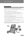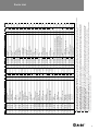
1
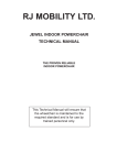
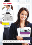
Service Manual
Battery Powered Tool
Contents
CONTENTS
Annual Service
Service Kit
Before Dismantling
4
4
Repairs & Major Service
Moulded Body Assembly
Pump Assembly
Motor, Gearbox, Electrical Assembly
Head Assembly
Trigger Mechanism
Housing Assembly
Reservoir Assembly
Troubleshooting
5
6
6
7
8
8
9
9
Assembly Diagram & Base Tool
10
Parts List
11
This manual is only for use by TFS authorized distributors and repair centres.
IMPORTANT: The warranty is invalidated if the installation tool is not identified
with a relevant serial number label. The label is positioned internally, at the base
of the handle, on the left moulding, 41. When replacing the moulded body a new
label, 83, must be inserted and marked by hand with the tool's original serial
number.
3
Annual Service
ANNUAL/500,000 CYCLE SERVICE
• Every 500,000 cycles the tool should be completely dismantled and new components should be used
where worn, damaged or recommended. All ‘O’ rings and seals should be renewed and lubricated with
MolyKote 111 grease before assembling.
• For an easy complete service, Textron Fastening Systems offer a complete service kit as detailed below.
Service Kit: 71600-99990
Spanners are specified in inches and across flats unless otherwise stated
Part No.
Description
Part No.
Description
07900-00006
Spatular
07900-00748
Threaded Sleeve Bullet
07900-00008
7
07900-00747
Valve Seat Tool
07900-00012
9
07900-00749
Threaded Sleeve Tool
07900-00015
5
/ x / Spanner
07900-00750
Valve Needle Sleeve
07900-00243
Screwdriver - Small
07900-00751
3mm Allen Key - Short Reach
07900-00333
Screwdriver - Medium
07900-00753
Circlip Pliers - Small
07900-00469
2.5mm Allen Key
07900-00754
Priming Pump
07900-00737
Piston Seal Sleeve
07900-00755
Grease - MolyKote 111 - 100g tube
07900-00738
Piston Seal Tool
07900-00756
Loctite® 243 Threadlocker
07900-00739
Piston Bullet
07900-00757
Scalpel
07900-00740
Cylinder Collar
07900-00760
Pozi Screwdriver
07900-00741
Guide Tube
07900-00788
Service Kit Storage Case
07900-00742
Insertion Rod
07900-00768
Reservoir Bullet
07900-00743
End Cap Assembly Tool
07900-00769
Trigger Tool
07992-00020
Grease - Moly-Lithium
1
/ x / Spanner
16
2
/16 x 5/8 Spanner
8
11
16
Before dismantling:
• Disconnect the battery before any servicing or dismantling is attempted, unless specifically instructed otherwise.
• Care must be taken at all times to ensure that conditions are clean so that no foreign matter enters the tool or serious
damage may result.
• Empty the oil from the tool following the first three steps of the priming procedure. Refer to the priming procedure on pages 14
and 15 of the Instruction Manual.
• Remove the nose equipment.
For a complete service of the tool, we advise that you proceed with dismantling of sub-assemblies in the order shown on
page 5. After dismantling the tool we recommend that you replace all seals.
On reassembly it is essential to prime the tool and fit an appropriate nose assembly prior to operating.
4
Repairs & Major Service
M O U L D E D B O D Y A S S E M B LY
IMPORTANT: The warranty is invalidated if the installation tool is not identified with a relevant serial number label.
The label is positioned internally, at the base of the handle, on the left moulding, 41. When replacing the moulded
body a new label, 83, must be inserted and marked by hand with the tool's original serial number.
The moulded body assembly includes items 1, 2, 33, 41 to 45, 47, 48, 53, 54, 81 and 83. These parts are only available as
a complete Body Moulding Assembly Kit (part number 71600-99600), unless the individual part numbers are provided in the
parts list.
• Remove and discard label 42 from the right moulding 43 to reveal the hidden screw.
• Remove the nose tip spanner 53 and two nose tips from the moulded body.
• Place the tool on its side and using the pozi screwdriver unscrew all eight pozi screws 45 in the moulded body.
• Remove the right moulding 43 leaving the main internal mechanism within the left moulding 41 as shown on page 10.
• Remove the vent screen 54, battery retainer spring 47 and dowel pin 48 from the left moulding 41.
• Before removing the main internal mechanism ensure that the electrical control circuit 5 and the reservoir 73 are released
from the mounting points within the moulding.
• Holding the tool by the motor and gearbox assembly 3 remove the main internal mechanism from the moulding.
Assemble in reverse order to dismantling noting the following points:
• Place the main internal mechanism into the left moulding 41, first ensuring that the electrical control circuit 5 and the
reservoir 73 are correctly placed within the mounting positions provided. The circuit board must be positioned so that the
heat sink is facing forward and the black and blue wires are at the top. The contact holder 4 must be positioned with the
positive symbol in the left moulding 41 as shown in the diagram below.
• The contact holder is designed to enable correct orientation in the mouldings. Care must be taken to ensure that the raised
portion on the right moulding 43 fits within the indent on the negative side of the contact holder 4.
• When replacing the right moulding 43 take care to ensure that no wires are trapped and correct alignment with the electrical
control circuit 5 and the vent screen 54 are achieved.
• When the moulded body is fully assembled with all eight pozi screws 45, insert new case label 42 on the right moulding 43.
IMPORTANT: Correct orientation of the contact holder 4 must be achieved when assembling into mouldings 41 and
43. Incorrect assembly will cause short circuit and failure of electrical control circuit.
Left Hand
Moulding
Recessed
Edge
Contact Holder
5
Repairs & Major Service
P U M P A S S E M B LY
The pump assembly includes items 29, 35, 36, 37, 49, 51 and one of the following plunger seal combinations, either seals
(37 and 50 2 off) or (37, 84 and 85). These parts are only available fully assembled as a complete Pump Assembly Kit (part
number 71600-99601), unless the individual part numbers are provided in the parts list.
• Completely remove the main internal mechanism from the left and right mouldings 41, 43, as described on page 5.
• To gain access to the pump attachment screws 29 the trigger assembly, items 34, 40, must be removed. Using the circlip
pliers remove one circlip 67 from pin 66. Push the pin out allowing the trigger lever 34 and trigger button 40 to be removed.
• Hold the main internal mechanism and pump block 51 securely in position and using the 3 mm allen key remove the four
attachment screws 29. Remove the complete pump assembly from the housing 24. Care must be taken when removing
the pump assembly as the plunger 36 will be spring loaded.
• Remove the plunger 36 and spring 35 from the pump block 51 taking care not to damage the seals, plunger surface and
the pump block bore.
• Remove ‘O’ ring 49 from housing 24 and discard.
Assemble in reverse order to dismantling noting the following points:
• Clean the plunger 36 and apply a small amount of Molykote 111 grease to the seals using the spatula.
• Clean the pump block 51 bore and then lubricate with Molykote 111 grease using the spatula.
• Place spring 35 over the sealed plunger, align the end of the plunger with the pump block 51 bore and push into place
until the seals are no longer visible. When inserting the plunger take care not to damage the seals on the rim of the pump
block bore.
• Apply a light film of Loctite® 243 threadlocker to all four screws 29.
• Attach the pump assembly onto the housing 24 as before using four screws 29 and the 3 mm allen key.
• Finally assemble the trigger assembly, items 34, 40, and pin 66 in reverse order to dismantling.
M O T O R , G E A R B O X A N D E L E C T R I C A L A S S E M B LY
The motor, gearbox and electrical assembly includes items 3, 4, 5, 28, 38 and 52. These parts are only available as a
complete assembly (part number 71600-99602), unless the individual part numbers are provided in the parts list.
• Completely remove the main internal mechanism from the left and right mouldings 41, 43, as described on page 5.
• Remove the ‘pump assembly’ as described above.
• Using the small screwdriver remove the two screws 28 that retain the micro-switch to the switch bracket 27.
• Using the 3 mm allen key remove all three screws 38 and washers 52 attaching the gearbox to the housing 24.
• Remove the complete motor, gearbox and electrical assembly 3, 4 and 5 from the housing 24.
Assemble in reverse order of dismantling noting the following points:
• Ensure that the motor and gearbox assembly, when connected to the housing 24, is orientated so that the groove in the
gearbox mounting plate is at the top.
• Apply Loctite® 243 threadlocker to all three screws 38.
• DO NOT USE UNDUE FORCE when inserting the three screws 38 into the housing 24.
6
Repairs & Major Service
H E A D A S S E M B LY
The head assembly consists of three assembly kits, Cylinder Assembly Kit (part number 71600-99603), Piston Assembly Kit
(part number 71600-99604) and Head Seal Kit (part number 71600-99605) containing items 6 to 18, 21, 22, 23, 30 and
32. These parts are only available as complete kits unless the individual part numbers are provided in the parts list.
• Completely remove the main internal mechanism from the left and right mouldings 41, 43, as described on page 5.
• Remove the complete motor, gearbox and electrical assembly 3, 4 and 5 as described on page 6.
• Unscrew locknut 31 and jaw spreader housing 20 from the piston 18.
• Using the 3 mm and 2.5 mm allen keys remove screws 11, 23, 30, clamping the cylinder 32 to the housing 24.
• Remove the head assembly from the housing. Remove ‘O’ ring 56 from the housing and discard.
• Grip the head assembly in a vice using soft jaws to avoid damage.
• Using the end cap assembly tool unscrew and remove the cylinder cap assembly, items 6, 7, 8, 9 from the rear of the
cylinder 32. Care must be taken as the cylinder cap 7 will be spring loaded.
• Remove and discard the spring 10 from inside the cylinder 32.
• Push the piston 18 to the rear and out of the cylinder 32 taking care not to damage the cylinder bore.
• Using the medium screwdriver enter the rear of the cylinder 32, lever the rod seal 15 from the groove and cut through
with a scalpel taking care not to damage the cylinder bore or the seal groove. Using the spatula push the rod seal,
followed by bearing ring 16 and ‘O’ ring 17 to the rear and out of the cylinder. If at any time the cylinder bore or seal
groove become damaged the cylinder must be replaced.
• Using a scalpel cut through and remove the piston seal 14 from the piston 18. Then remove bearing ring 13 and ‘O’ ring
12. Take care not to damage the piston when cutting the seal.
Assemble in reverse order to dismantling noting the following points:
• Clean all components before assembling.
• To aid assembly of seals apply a light coating of Molykote 111 grease to both the seals and the assembly tools.
• Lubricate the cylinder 32 bore and seal grooves with Molykote 111 grease. Insert the bearing ring 16 into place within
cylinder. With the aid of the spatula insert the ‘O’ ring 17. Place the rod seal 15 onto the insertion rod ensuring correct
orientation. Push the guide tube into the cylinder bore and push the insertion rod with the seal into place through the guide
tube ensuring seal is correctly seated. Pull the insertion rod out then the guide tube.
• Lubricate the piston 18 shaft and seal grooves with Molykote 111 grease and fit ‘O’ ring 12 and bearing ring 13. Place
the piston seal sleeve over the piston shaft, then slide the piston seal 14 over the sleeve and into position using the piston
seal tool ensuring correct orientation.
• Insert the cylinder collar into the back of the cylinder 32. Screw the piston bullet onto the piston 18 and push the piston with
the seals through the cylinder collar as far as it will go. Unscrew the bullet off the piston and remove the cylinder collar.
• Apply a light coating of Moly-lithium grease to the surface and ends of the spring 10 before inserting onto the piston 18
within the cylinder.
• Screw the cylinder cap assembly, items 6, 7, 8, 9, into the cylinder 32 using the ‘T’-bar and end cap assembly tool.
• Insert ‘O’ ring 56 into the housing and lubricate with Molykote 111 grease.
• Fit the head assembly to the housing 24 using the three screws 11, 23, 30, coated with Loctite® 243 threadlocker.
7
Repairs & Major Service
TRIGGER MECHANISM
The trigger mechanism includes items 34, 40, 58 to 69. These parts are only available as a complete Trigger Mechanism
Kit (part number 71600-99606), unless the individual part numbers are provided in the parts list.
• Completely remove the main internal mechanism from the left and right mouldings 41, 43, as described on page 5.
• Using the circlip pliers remove one circlip 67 from pin 66. Push the pin out allowing the trigger lever 34 and trigger button
40 to be removed.
• Using the circlip pliers carefully remove circlip 68 from the valve needle 61, followed by shim 69, trigger plate 65 and
spring 60. Discard the spring 60.
• Using the threaded sleeve tool unscrew and remove the threaded sleeve 64 from the housing 24. Remove ‘O’ ring 62
from the threaded sleeve and discard.
• Remove the valve needle 61 from the housing 24, then remove and discard the spring 60 from the valve needle 61. Using
a scalpel cut ‘O’ ring 63 from the valve needle taking care not to damage the seal groove.
• Using the valve seat tool unscrew the valve seat 59 and remove from the housing 24. Remove bonded seal 58 from valve
seat and discard.
Assemble in reverse order to dismantling noting the following points:
• Clean all components before assembling.
• Lubricate valve needle 61 shaft and seal groove with Molykote 111 grease and place the valve needle tool over the end of
the valve needle 61. Slide ‘O’ ring 63 over the valve needle sleeve and into the seal groove on valve needle. Remove the
valve needle sleeve from the valve needle.
• Lubricate threaded sleeve 64 with Molykote 111 grease and place the threaded sleeve bullet over the end of the threaded
sleeve. Slide ‘O’ ring 62 over the threaded sleeve bullet and into the seal groove on threaded sleeve. Remove bullet from
threaded sleeve.
• DO NOT USE UNDUE FORCE when inserting the valve seat 59 into the housing 24.
• When fitting threaded sleeve 64 into housing 24, ensure the component is screwed fully down until stopping against the
valve seat 59.
• When fitting trigger plate 65, ensure correct orientation is achieved.
• Using the trigger tool and pin 66 in place of the trigger lever 34, fully compress the trigger plate 65 into the threaded
sleeve 64 against the spring 60. The end of the valve needle 61 will become exposed. Place the shim 69 over the valve
needle and then insert the circlip 68 into the groove using the circlip pliers. Release and remove the trigger tool.
H O U S I N G A S S E M B LY
The housing assembly consists of items 24 to 27, 38 and 75, all of which are available as individual parts. The assembly
also contains items 39, 55, 56, 57, 70 and 76. These parts are only available as a complete Housing Hydraulic Kit (part
number 71600-99607).
• Completely remove the main internal mechanism from the left and right mouldings 41, 43, as described on page 5.
• Do not remove screws 25, 38, from the housing 24.
• Using medium screwdriver unscrew seal screw 75 from housing 24. Remove ‘O’ ring 76 from seal screw.
• Using medium screwdriver unscrew inlet check valve 70 from housing 24.
• In order to remove outlet check valve 55 the head assembly must be removed as described on page 7.
• Using medium screwdriver unscrew outlet check valve 55 from housing 24. Remove ‘O’ ring 57 from outlet check valve
and discard.
• Assemble in reverse order to dismantling.
8
Repairs & Major Service
R E S E R V O I R A S S E M B LY
The reservoir assembly includes items 21, 22, 25, 78, 82 and 71 to 74. These parts are only available as a complete
Reservoir Assembly Kit (part number 71600-99608), unless the individual part numbers are provided in the parts list.
• Completely remove the main internal mechanism from the left and right mouldings 41, 43, as described on page 5.
• Using the 3 mm allen key remove screw 21 and bonded seal 22 from reservoir 73.
• Using the spatular remove 'O' ring 72 from reservoir 73 and discard.
• Remove reservoir 73 from reservoir adapter 74.
• Using the 2.5 mm allen key, remove screw 25 attaching reservoir adapter 74 to housing 24.
• Remove reservoir adapter 74 from housing 24.
• Remove 'O' ring 71 from reservoir adapter 74 and discard.
• Do not remove the filter 78, or the 'O' ring 82, from the reservoir adapter 74 unless damaged. If removed discard both
items.
Assemble in reverse order to dismantling noting the following points:
• Lubricate both ‘O’ ring 71 and seal groove on reservoir adapter. Place ‘O’ ring 71 in reservoir adapter 74.
• Using 2.5 mm allen key and screw 25 fit reservoir adapter 74 to housing noting correct orientation with the holes.
• Slide open end of reservoir 73 over reservoir adapter 74 and into position within the groove.
• Place the reservoir bullet over the closed end of reservoir 73. Slide ‘O’ ring 72 completely over the bullet until it falls into
place around the end of the reservoir 73, holding it in securely around the reservoir adapter 74.
• Ensure that the reservoir 73 is correctly positioned on the reservoir adapter 74, so that the flat face on the metal part of
the reservoir is at the top.
IMPORTANT: Check the tool against daily and weekly servicing.
Priming is ALWAYS necessary after the tool has been dismantled and prior to operating.
TROUBLESHOOTING
SYMPTOM
POSSIBLE CAUSE
REMEDY
PA G E R E F.
Fastener fails to break
Trigger mechanism springs worn
Replace trigger mechanism
8
Jaws will not release
Damaged spring in head assembly
Fit new spring
7
Pump plunger jammed
Replace pump spring
6
if head piston static
Inlet check valve faulty
Replace inlet check valve
8
if head piston pulsing
Outlet check valve faulty
Replace outlet check valve
8
Tool fails to operate -
Motor or gearbox failure
Test and replace any defective equipment
6
motor not operational
Electrical control circuit failure
Test and replace any defective equipment
6
broken stem of fastener
Tool fails to operate motor operational:
9
10
69
68
56
57
70
76
71
66
67
65
64
63
62
61
60
59
54
81
25
74
82
73
78
22
21
TRIGGER MECHANISM
58
VIEW ON A
75
72
ENLARGED VIEW OF
60
55
1
2
47
53
5
4
3
48
5
49
6
50
51
38
52
7
8
9
10
11
46
12
45
13
4
15
40
38
39
17
33
35
34
A
36
37
16
42, 43 Right Hand
41, 44 Left Hand
14
18
85
37
30
20
21
22
ALTERNATIVE PUMP
ARRANGEMENT
29
5 Ref
28
25
26
27
24
23
84
INTERNAL MECHANISM
(EXCLUDING MOULDINGS)
31
32
19
General Assembly of Base Tool 71600-02000
1
2
3
4
5
6
7
8
9
10
11
12
13
14
15
16
17
18
19
20
21
22
23
24
25
26
27
28
29
30
31
32
33
34
35
36
37
38
39
40
41
42
43
44
DESCRIPTION
Lid torsion spring
Collector lid
Motor & gearbox assembly
Contact holder
Electrical control circuit
Circlip
Cylinder cap
Piston sleeve
O-ring
Compression spring
Socket csk head screw
O-ring (piston)
Piston bearing ring
Piston seal
Rod seal
Cylinder bearing ring
O-ring (cylinder)
Piston
O-ring
Jaw spreader housing
Button head screw
Bonded seal
Socket cap head screw
Housing
Socket cap head screw
Steel washer
Switch bracket
Slotted cheese head screw
Socket cap head screw
Socket cap head screw
Locknut
Cylinder
Nose tip holder
Trigger lever
Compression spring
Plunger
O-ring
Socket cap head screw
Bonded seal
Trigger button
Left moulding
Case label RH
Right moulding
Case label LH
1
1
1
1
1
1
1
1
1
1
1
1
1
1
1
1
1
1
1
1
2
2
1
1
2
1
1
2
4
1
1
1
1
1
1
1
1
4
1
1
1
2
1
1
6
9
4
2
2
2
1
5
4
9
9
9
9
✔
1
2
6
✔
✔
3
✔
36
36
6
✔
✔
9
9
1
1
1
7
7
7
8
7
6
8
8
8
8
8
8
7
10
10
50
50
1
50
50
50
1
50
50
10
50
50
50
10
50
50
50
78
79
80
81
82
83
84
85
45
46
47
48
49
50
51
52
53
54
55
56
57
58
59
60
61
62
63
64
65
66
67
68
69
70
71
72
73
74
75
76
77
QTY SPARES ORDER QTY ITEM
2
2
9
3
3
5
4
5
3
3
3
3
9
5
5 8
5
4
4
4
4
4
4
4
4
4
2
2
PART Nº
07001-00652
07007-01954
71600-02022
07007-01957
07003-00353
see note
see note
07002-00156
71600-02024
see note
see note
see note &
see note
see note
see note
see note
see note
see note
see note
see note
see note
see note
07004-00104
07004-00103
see note
see note
see note
see note
see note
see note
71600-02013
see note
07007-01965
07007-01966
07007-01967
07007-01968
07007-01969
see note
07007-01960
07900-00759
see note
see note
71600-02035
see note
see note
DESCRIPTION
Pozi screw
Battery
Battery retainer spring
Dowel pin
O-ring
O-ring
Pump block
Steel washer
Nose tip spanner
Vent screen
Outlet check valve
O-ring (housing)
O-ring for item 55
Bonded seal
Valve seat
Compression spring
Valve needle
O-ring
O-ring
Threaded sleeve
Trigger plate
Pin
Circlip
Circlip
Steel shim washer
Inlet check valve
O-ring
O-ring
Reservoir
Reservoir adapter
Seal screw
O-ring
Battery charger - 220/240V~50Hz (UK)
Battery charger - 220/240V~50Hz (Europe)
Battery charger - 220/240V~50Hz (Australia)
Battery charger - 110V~60Hz (USA, Canada)
Battery charger - 100V~50/60Hz (Japan)
Filter
Storage case
Tool Instruction Manual - UK version
Collector lid buffer
'O' Ring
Blank serial number label
Energised PTFE seal
Energised lip leal
8
1
1
1
1
2
1
3
1
1
1
1
1
1
1
2
1
1
1
1
1
1
2
1
1
1
1
1
1
1
1
1
1
1
1
1
1
1
1
1
1
1
1
1
1
9
3
9
2
2
✔
✔
3
✔
✔
✔
✔
✔
5
✔
9
9
2
2
2
1
9
9
5
58
5
4
4
4
4
4
4
4
4
4
4
4
4
5
3
3
3
3
✔
9
50
1
1
1
1
1
1
1
1
50
50
50
10
50
1
10
50
50
QTY SPARES ORDER QTY
1
2
3
4
5
6
7
8
9
Note
Motor, Gearbox and Electrical Assembly (part number 71600-99602). These items are only available as a complete assembly unless individual part numbers are given, where the minimum order quantity shall apply.
Pump Assembly Kit (part number 71600-99601). These items are only available as a complete assembly unless individual part numbers are given, where the minimum order quantity shall apply.
Reservoir Assembly Kit (part number 71600-99608). These items are only available as a complete assembly kit unless individual part numbers are given, where the minimum order quantity shall apply.
Trigger Mechanism Kit (part number 71600-99606). These items are only available as a complete assembly kit unless individual part numbers are given, where the minimum order quantity shall apply.
Housing Hydraulic Kit (part number 71600-99607). These items are only available as a complete kit.
Cylinder Assembly Kit (part number 71600-99603). These items are only available as a complete assembly kit unless individual part numbers are given, where the minimum order quantity shall apply.
Piston Assembly Kit (part number 71600-99604). These items are only available as a complete assembly kit unless individual part numbers are given, where the minimum order quantity shall apply.
Head Seal Kit (part number 71600-99605). These items are only available as a complete assembly kit unless individual part numbers are given, where the minimum order quantity shall apply.
Body Moulding Assembly Kit (part number 71600-99600). These items are only available as a complete assembly kit unless individual part numbers are given, where the minimum order quantity shall apply.
✔ These items are available as individual spares subject to the minimum order quantity.
9
5
4
9
6
9
4
2
2
2
8
8
8
8
8
8
7
7
7
8
7
9
1
1
1
PART Nº
71600-02004
see note
see note
see note
see note
07004-00102
see note
see note
see note
see note
07001-00650
see note
see note
see note
see note
see note
see note
see note
07003-00277
71210-02101
07001-00654
07003-00194
07001-00646
71600-02009
07001-00647
07002-00155
71600-02014
07001-00648
07001-00651
07001-00645
71600-02026
see note
see note
see note
see note
see note
see note
07001-00649
see note
see note
see note
71600-02028
see note
71600-02027
ITEM
Parts List
11
GERMANY
SPAIN
Textron Fastening Systems Pty Ltd
Textron Verbindungstechnik GmbH
Textron Sistemas de Fijación S.A.
891 Wellington Road
Klusriede 24
c/ Puerto de la Morcuera, s/n
Rowville
D - 30851 Langenhagen
Poligono Industrial Prado Overa
Victoria 3178
Tel:
Autovia Madrid Toledo Km 7.8
Tel:
Fax: +49 511 7288 133
+613 9764 3877
+49 511 7288 0
Fax: +613 9755 7352
Es - 28916 Leganes (Madrid)
Tel:
+349 134 16767
ITALY
Fax: +349 134 16740
AUSTRIA
Textron Sistemi di Fissaggio SRL
Textron Verbindungselemente GmbH
Via Manin 350-21
UNITED KINGDOM
Industriestrasse B-13 Halle 2
It- 20099 Sesto San Giovanni
Textron Fastening Systems Ltd
A-2345 Brunn/Gebirge
Milano
Mundells
Tel:
Tel:
Welwyn Garden City
+43 2236 33273
+39 02 262 9171
Fax: +43 2236 33274
Fax: +39 02 242 4956
CANADA
JAPAN
Avdel Division of Textron Canada Ltd
Avdel Kabushiki Kaisha
© T E X T R O N FA S T E N I N G S Y S T E M S 2 0 0 0
AUSTRALIA
Hertfordshire
AL7 1EZ
Tel:
+44 1707 668668
Fax: +44 1707 338828
87 Disco Road
7F, New Erimo Building,
Rexdale
2-2-1, Senba Nishi,
USA
Ontario M9W 1M3
Mino, Osaka 562-0036
Avdel Cherry Textron Inc.
Tel:
Tel:
614 NC Highway 200 South
+1 416 679 0622
+81 727 30 0803
Fax: +1 416 679 0678
Fax: +81 727 30 0807
CHINA
SOUTH KOREA
Textron Fastening Systems China Ltd
Avdel Korea Limited
Room 1708 Nanyang Plaza
Sam Young Building
57 Hung To Road
1486-2 Seo Cho-Dong
Kwun Tong
Seo Cho-Ku
Kowloon
Seoul
Hong Kong
Tel:
Tel:
Fax: +82 2 586 9277
Stanfield, North Carolina 28163
Tel:
+1 704 888-7100
Fax: +1 704 888-0258
Textron Fastening Systems
Commercial Solutions HQ
516 Eighteenth Avenue
Rockford, Illinois 61104
Tel:
+852 2950 0630
+1 815 961-5000
Fax: +1 815 961-5010
Fax: +852 2950 0022
FRANCE
Textron Industries S.A.
33 bis, rue des Ardennes
BP4, 75921 Paris Cédex 19
Tel:
+33 1 4040 8000
Fax: +33 1 4040 8040
07900-00760 GB/ JANUARY 2002
+82 2 586 9274/5/6