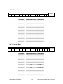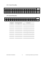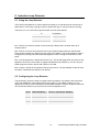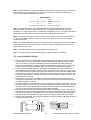
1
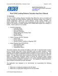
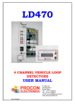
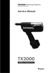
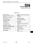
PL400
PROGRAMMABLE LOGIC
CONTROLLER WITH
INDUCTIVE LOOP DETECTOR
USER MANUAL
P.O.Box 24
STANFIELD 3613
SOUTH AFRICA
29/06/2004 V01
Tel:
Fax:
Email:
Web:
+27 (031) 7028033
+27 (031) 7028041
[email protected]
www.proconel.com
TABLE OF CONTENTS
1.
AN OVERVIEW OF THE PL400 PROGRAMMABLE LOGIC CONTROLLER......................... 3
1.1
DESCRIPTION ........................................................................................................................ 3
2. PL400 GENERAL INFORMATION ............................................................................................... 4
2.1
PHYSICAL DIMENSIONS ..................................................................................................... 4
2.2
GROUNDING/SHIELDING.................................................................................................... 4
3. PL400 HARDWARE ....................................................................................................................... 5
3.1
SPECIFICATIONS .................................................................................................................. 5
3.2
WIRING TERMINALS ........................................................................................................... 5
3.3
FRONT PANEL DESCRIPTION. ........................................................................................... 6
4. CONFIGURATION ......................................................................................................................... 7
4.1
HARDWARE CONNECTIONS. ............................................................................................. 7
4.1.1
Connecting the Power....................................................................................................... 7
4.1.2
Connecting the Inputs. ...................................................................................................... 7
4.1.3
Connecting the Outputs. ................................................................................................... 8
4.1.4
Connecting the Inductive Loop......................................................................................... 8
4.1.5
Connecting the programming port to a PC. ...................................................................... 9
4.2
PL400 CPU............................................................................................................................. 10
4.2.1
Program Memory............................................................................................................ 10
4.2.2
Data Memory.................................................................................................................. 10
4.2.3
Data Memory Map.......................................................................................................... 11
4.2.4
Digital Input Map. .......................................................................................................... 12
4.2.5
Digital Output Map......................................................................................................... 12
4.2.6
Timer Map. .....................................................................................................................13
4.2.7
Counter Map. .................................................................................................................. 13
4.2.8
Control Relay Map. ........................................................................................................ 14
4.2.9
System Relay Map.......................................................................................................... 14
5. Inductive Loop Detector................................................................................................................. 15
5.1
Using the Loop Detector......................................................................................................... 15
5.2
Configuring the Loop Detector............................................................................................... 15
5.3
Loop Installation Guide. ......................................................................................................... 16
6. Modbus Memory Map ( MODULE TYPE = 40) ........................................................................... 17
7. Ladder Logic Function Blocks ....................................................................................................... 19
PROCON ELECTRONICS
2
PL400 Programmable Logic Controller
1. AN OVERVIEW OF THE PL400 PROGRAMMABLE LOGIC
CONTROLLER
1.1 DESCRIPTION
The PL400 PLC has been developed as a versatile controller for use in parking or access
control applications. The PLC can be used to operate gates or barriers where an inductive
loop detector is required to sense the presence of vehicles. The fact that the controller is
programmable enables the user to program their own unique logic requirements and not be
restricted by a pre-programmed unit.
The PL400 PLC is programmed in ladder logic. PROCON’s PROSOFT windows-based PC
software is used to generate the ladder diagram, compile the program, and then download the
program to the PL400 via the programming port on the front of the unit.
The I/O consists of 8 digital inputs and 4 relay outputs. The inputs are opto-isolated and a
built in field supply is used to power the inputs so no external power supply is required. The
PLC has a user programmable toggle switch on the front, which can be incorporated into the
ladder program as manual inputs. Two led’s are also provided for user functions.
All wiring is done with screw terminals on removable connectors.
The programming port requires the use of a special adaptor to connect it to an RS232
communications port of a PC. This port supports the Modbus RTU protocol and all of the
internal registers and I/O status can be accessed through this port.
PROCON ELECTRONICS
3
PL400 Programmable Logic Controller
2. PL400 GENERAL INFORMATION
2.1 PHYSICAL DIMENSIONS
The PL400 enclosure is shown below. The module has been designed with a quick snap-in
assembly for mounting onto DIN-rail’s as per DIN EN 50 022.
46.00 mm
106 mm
60.00 mm
59.50 mm
70.00 mm
2.2 GROUNDING/SHIELDING
In most cases, the PL400 will be installed in an enclosure along with other devices, which
generate electromagnetic radiation. Examples of these devices are relays and contactors,
transformers, motor controllers etc. This electromagnetic radiation can induce electrical noise
into both power and signal lines, as well as direct radiation into the module causing negative
effects on the system. Appropriate grounding, shielding and other protective steps should be
taken at the installation stage to prevent these effects. These protective steps include control
cabinet grounding, module grounding, cable shield grounding, protective elements for
electromagnetic switching devices, correct wiring as well as consideration of cable types and
their cross sections.
PROCON ELECTRONICS
4
PL400 Programmable Logic Controller
3. PL400 HARDWARE
3.1 SPECIFICATIONS
POWER REQUIREMENT:
200 - 260VAC 50/60Hz.
8 X INPUTS:
These inputs may be activated by a potential free relay
contact or open collector NPN transistor output. These inputs
are isolated from the logic.
4 X OUTPUTS:
These outputs are a normally open relay contact rated at
6A/220VAC (resistive).
INDICATORS:
LED indicators show power, user1, user2 and programming
communications.
LOOP RESPONSE TIME:
Approximately 120ms after vehicle enters loop.
DETECTOR TUNING RANGE: 15 - 1500 uH.
LOOP PROTECTION:
Loop isolation transformer with lightning protection.
CONNECTORS:
2 X 12 Way Removable Connectors with screw terminals.
DIMENSIONS:
106mm (HIGH) X 70mm (WIDE) X 59.5mm (DEEP)
OPERATING TEMPERATURE: -20°C to +60°C
STORAGE TEMPERATURE:
-20°C to +65°C
HUMIDITY:
up to 95% non condensing
3.2 WIRING TERMINALS
24 – Earth
12 – 220VAC Neutral
23 – Loop Detector
11– 220VAC Live
22 – Loop Detector
10 – Relay 1 N/C
21 – Input Common
9 – Relay 1 Common
20 – Input 8
8 – Relay 1 N/O
19 – Input 7
7 – Relay 2 N/O
18 – Input 6
6 – Relay 2 Common
17 – Input 5
5 – Relay 3 N/O
16 – Input 4
4 – Relay 3 Common
15 – Input 3
3 – Relay 4 N/O
14 – Input 2
2 – Relay 4 Common
13 – Input 1
1 – Relay 4 N/C
Pl400
PROCON ELECTRONICS
5
PL400 Programmable Logic Controller
3.3 FRONT PANEL DESCRIPTION.
The led's on the front panel of the PL400 Module are used to indicate power, and user
defined LED1 and LED2. A programming LED is used to indicate communications with a PC
during programming and Debugging.
A toggle switch is provided which allows you to use this in your application, for as an
example, a manual override switch.
Power
LED
User
LED2
Programming
Port LED
User
LED1
Programming
Port
User Two
Way toggle
switch
PROCON ELECTRONICS
6
PL400 Programmable Logic Controller
4. CONFIGURATION
4.1 HARDWARE CONNECTIONS.
4.1.1 Connecting the Power.
Power must be applied to terminal 11 (220VAC LIVE) and terminal 12 (220VAC NEUTRAL).
When the power is initially applied the power LED will illuminate and all other LED's will be off.
12 – 220VAC Neutral
11– 220VAC Live
As the PLC is often used to control machinery, which could present a risk of personal injury or
damage to equipment, it is good practice to wire an external emergency stop circuit to the
power supply on the PLC. The circuit below shows how a mechanical contactor (MC) is used
with start/stop buttons to provide this facility.
Circuit Breaker
MC
Emergency
Stop
Power Supply
220VAC
50/60Hz
Supply to PL400
and Output
Circuits
Start
MC
MC
MC
4.1.2 Connecting the Inputs.
The inputs are sourced from an internally isolated power supply and can be switched by a
potential free contact or a NPN transistor. The inputs all share the common terminal.
21 – Input Common
20 – Input 8
19 – Input 7
18 – Input 6
17 – Input 5
16 – Input 4
15 – Input 3
14 – Input 2
13 – Input 1
PROCON ELECTRONICS
7
PL400 Programmable Logic Controller
4.1.3 Connecting the Outputs.
The outputs are potential free relay contacts. Note that only Relay output 1 and 4 have
normally closed contacts as well as normally open contacts.
10 – Relay 1 N/C
9 – Relay 1 Common
8 – Relay 1 N/O
7 – Relay 2 N/O
6 – Relay 2 Common
5 – Relay 3 N/O
4 – Relay 3 Common
3 – Relay 4 N/O
2 – Relay 4 Common
1 – Relay 4 N/C
The outputs may be used to control the direction of a motor. For example output 1 could be
used to control the forward direction of the motor and output 2 used to control the reverse
direction. It could be possible under fault conditions that both outputs switch on at the same
time. It is considered good practice to interlock the two outputs both in the ladder program
and using external mechanical contactors. The diagram below shows how this is done.
O1
MC 2
MC 1
PL400
Outputs
O2
MC 1
MC 2
4.1.4 Connecting the Inductive Loop.
Refer to the chapter further in the manual on installing the inductive loop. The diagram below
shows how to connect the loop to the PL400.
24 – Earth
LOOP
TWISTED
23 – Loop Detector
22 – Loop Detector
CABLE
PROCON ELECTRONICS
8
PL400 Programmable Logic Controller
4.1.5 Connecting the programming port to a PC.
The PL400 programming port is connected to a RS232 communications port on the PC using
a special programming cable supplied by Procon. The RS232 connector is a DB-9 plug which
plugs into the PC.
PROCON ELECTRONICS
9
PL400 Programmable Logic Controller
4.2 PL400 CPU.
The CPU (central Processing Unit) performs all of the tasks that are required to make the
PLC function and run your ladder program. Some of the tasks include:
1.
2.
3.
4.
5.
6.
Reading the status of the inputs.
Executing the program.
Updating the outputs.
Doing diagnostics.
Servicing the communications ports.
Running the timers.
4.2.1 Program Memory.
The programming port is used to program the PLC. The program which is sent from the PC
using the ProSoft ladder editor, is stored in FLASH memory. This memory does not get lost
when the power fails and so will remain permanently in the PLC until it is reprogrammed.
4.2.2 Data Memory.
All the variables used in the program are stored in Data memory. Both the Digital and Analog
values are stored in this memory along with the timers, counters, and user memory.
The memory is divided up into 3 sections.
1. RAM – Random Access Memory. This memory is the most widely used memory and is
where most of the data is stored. All timers, counters, I/O statuses and system
information use this memory. If the power fails then all the information in this memory is
lost and is re-initialized to zero when the PLC starts again.
2. EEPROM – This memory is used to store parameters such as set-points and
configuration data as it retains its memory when the power is turned off. The one point to
remember is that this memory can only be written to 10 000 times before it wears out so
you must not write to this memory all the time as you can with RAM.
3. BBRAM (Optional extra) – This is battery backed RAM and also retains its memory when
the power is switched off. This memory is slow compared to RAM and should not be used
where normal RAM can be used. This memory is ideal for storing values such as used in
counting applications. The Real time clock is also stored in this memory.
PL400
0
RAM
113
EEPROM
153
BBRAM
(Option)
172
PROCON ELECTRONICS
10
PL400 Programmable Logic Controller
4.2.3 Data Memory Map.
All of the variables used in the PLC are stored in data memory. In order for your program to
get access to these variables you need to know the memory address. The memory address
starts at zero and the size depends on the PLC being used. Each memory location consists of
16 bits. Thus one memory location can be used to store the status of 16 digital I/O points or
an analog value from 0 to 65535. Some of the ladder functions use two consecutive memory
locations to store larger values. Refer to the ProSoft user manual to find out about the ladder
functions.
PL400 MEMORY MAP
Memory Type
Module Type = 40
Digital Inputs
Digital Outputs
Timer Status
Counter Status
Control Relays
System Relays
Timer Memory
Counter Memory
User RAMMemory
User EEPROM
User BBRAM
Digital Reference
I1 to I14
O1 to O6
T1 to T16
C1 to C16
R1 to R64
S1 to S32
PROCON ELECTRONICS
Memory Address
M0
M1
M2
M3
M4
M5 – M8
M9 – M10
M13 – M28
M29 – M44
M45 – M112
M113 – M152
M153 – M172
-
11
Quantity
1
14
6
16
16
64
32
16
16
68
40
20
PL400 Programmable Logic Controller
4.2.4 Digital Input Map.
MSB
15 14
-
13
I14
12
I13
11
I12
10
I11
Bit Number
0
1
2
3
4
5
6
7
8
9
10
11
12
13
14
15
PL400 DIGITAL INPUTS
9
8
7
6
5
4
I10 I9 I8 I7 I6 I5
Digital Input Number
I1
I2
I3
I4
I5
I6
I7
I8
I9
I10
I11
I12
I13
I14
-
3
I4
2
I3
1
I2
LSB
0
I1
ADDRESS
LSB
0
O1
ADDRESS
M1
Description
Digital Input 1
Digital Input 2
Digital Input 3
Digital Input 4
Digital Input 5
Digital Input 6
Digital Input 7
Digital Input 8
Toggle Switch 1
Toggle Switch 2
Loop Detect
Loop Pulse
Loop Detect LED
Loop Fault LED
-
4.2.5 Digital Output Map.
MSB
15 14
-
13
-
12
-
11
-
10
-
Bit Number
0
1
2
3
4
5
6
7
8
9
10
11
12
13
14
15
PROCON ELECTRONICS
PL400 DIGITAL OUTPUTS
9
8
7
6
5
4
O6 O5
Digital Input Number
O1
O2
O3
O4
O5
O6
-
12
3
O4
2
O3
1
O2
M2
Description
Relay Output 1
Relay Output 2
Relay Output 3
Relay Output 4
LED 1
LED 2
-
PL400 Programmable Logic Controller
4.2.6 Timer Map.
MSB
15
14
T16 T15
13
T14
12
T13
11
T12
10
T11
Bit Number
0
1
2
3
4
5
6
7
8
9
10
11
12
13
14
15
PL400 TIMER STATUS
9
8
7
6
5
T10 T9 T8 T7 T6
4
T5
Digital Input Number
T1
T2
T3
T4
T5
T6
T7
T8
T9
T10
T11
T12
T13
T14
T15
T16
3
T4
2
T3
1
T2
LSB
0
T1
ADDRESS
M3
Description
Timer 1
Timer 2
Timer 3
Timer 4
Timer 5
Timer 6
Timer 7
Timer 8
Timer 9
Timer 10
Timer 11
Timer 12
Timer 13
Timer 14
Timer 15
Timer 16
4.2.7 Counter Map.
MSB
15
14
C16 C15
13
C14
12
C13
11
C12
PL400 COUNTER STATUS
10
9
8
7
6
5
C11 C10 C9 C8 C7 C6
Bit Number
0
1
2
3
4
5
6
7
8
9
10
11
12
13
14
15
PROCON ELECTRONICS
Digital Input Number
C1
C2
C3
C4
C5
C6
C7
C8
C9
C10
C11
C12
C13
C14
C15
C16
13
4
C5
3
C4
2
C3
1
C2
LSB
0
C1
ADDRESS
M4
Description
Counter 1
Counter 2
Counter 3
Counter 4
Counter 5
Counter 6
Counter 7
Counter 8
Counter 9
Counter 10
Counter 11
Counter 12
Counter 13
Counter 14
Counter 15
Counter 16
PL400 Programmable Logic Controller
4.2.8 Control Relay Map.
MSB
15
R16
R32
R48
R64
14
R15
R31
R47
R63
13
R14
R30
R46
R62
12
R13
R29
R45
R61
11
R12
R28
R44
R60
10
R11
R27
R43
R59
PL400 CONTROL RELAYS
9
8
7
6
5
R10 R9
R8
R7
R6
R26 R25 R24 R23 R22
R42 R41 R40 R39 R38
R58 R57 R56 R55 R54
4
R5
R21
R37
R53
3
R4
R20
R36
R52
2
R3
R19
R35
R51
1
R2
R18
R34
R50
LSB
0
R1
R17
R33
R49
ADDRESS
M5
M6
M7
M8
4.2.9 System Relay Map.
MSB
15
14
S16 S15
S32 S31
13
S14
S30
12
S13
S29
11
S12
S28
Bit Number
0
1
2
3
4
5
6
7
8
9
10
11
12
13
14
15
10
S11
S27
PL400 SYSTEM RELAYS
9
8
7
6
5
S10 S9
S8
S7
S6
S26 S25 S24 S23 S22
Digital Input Number
S1
S2
S3
S4
S5
S6
S7
S8
S9
S10
S11
-
PROCON ELECTRONICS
14
4
S5
S21
3
S4
S20
2
S3
S19
LSB
1
0
S2
S1
S18 S17
ADDRESS
M9
M10
Description
ON
1st Scan
0.1 Second Clock Period
1 Second Clock Period
1 Minute Clock Period
CMP < MEM/K
CMP = MEM/K
CMP > MEM/K
PLC Running
PLC Re-Program Request
PLC Re-Program Acknowledge
-
PL400 Programmable Logic Controller
5. Inductive Loop Detector
5.1 Using the Loop Detector.
The inductive loop detector is used to detect the presence of vehicles and can be used as a
safety device, for arming or giving a pulse to operate the logic or may be used for counting.
The inputs I11 to I14 are used to get information from the loop detector.
Loop Detect
Loop Pulse
Loop Detect LED
Loop Fault LED
I11
I12
I13
I14
I11 – This bit is on when a vehicle is over the loop (in detect) and is off when there is no
vehicle present.
I12 – This bit is on for a short period of time to give a pulse output when the vehicle either
enters (goes into detect) or leaves the loop (goes out of detect). The mode register is used to
configure the pulse type and the pulse time register is used to configure the duration of the
pulse.
I13 – If the loop detect is in detect then this bit is on. This bit will toggle when the power is first
applied to the PL400. The number of toggles indicates the loop frequency. You can use your
ladder program to read in this bit and output it to an LED.
I14 – If there is a fault on the loop then this bit will come on. It is automatically turned off when
the fault is cleared and the detector has retuned.
5.2 Configuring the Loop Detector.
The parameters, which are used to configure the loop detector, are stored in the first section
of the user EEPROM. These parameters must be setup in your ladder program or in the
debug menu when you are running the ProSoft ladder software. They do not get lost when the
unit is powered off and so you only have to do the configuration once.
M113
M114
M115
M116
M117
M118
Detect Sensitivity
Detect UnSens
Detect On Filter
Detect Of Filter
Pulse Time
Pulse Mode
PROCON ELECTRONICS
X0.01%. - 2(0.02%) to 500(5%)
X0.01%. - 2(0.02%) to 500(5%)
X 10milliseconds.
X 10milliseconds.
X 10milliseconds.
0=puls on det, 1=puls on undet.
15
PL400 Programmable Logic Controller
M113 - Detect Sensitivity: The sensitivity determines the detect level of the loop. The smaller
the value the higher the sensitivity. The value can be from 2 to 500 and is multiplied by
0.01%. Some typical values are shown below.
Value in M113
2
0.02%
5
0.05%
10
0.1%
100
1.0%
M114 - Undetect Sensitivity: The undetect sensitivity determines the level at which the
detector decides that the vehicle has left the loop. The smaller the value the higher the
sensitivity. The value can be from 2 to 500 and is multiplied by 0.01%. This value must always
be less that the value in M113 and is usually about a half of the value in M113.
M115 – The Detect On Filter is a delay on detect and is usually used to prevent the detector
for giving false detect outputs. A minimum value of 10 is good for normal use but higher
values can be used.
M116 – The Detect Off Filter is a delay on undetect and is usually used to extend the detect
output after the vehicle has left the loop. A minimum value of 2 is good for normal use but
higher values can be used.
M117 – This value determines the pulse duration for the pulse bit.
M118 – The pulse mode is used to select pulse on detect or pulse on undetect.
5.3 Loop Installation Guide.
1. The loop and feeder should be made from insulated copper wire with a minimum crosssectional area of 1.5mm2. The feeder should be twisted with at least 20 turns per metre.
Joints in the wire are not recommended and must be soldered and made waterproof.
Faulty joints could lead to incorrect operation of the detector. Feeders which may pick up
electrical noise should use screened cable, with the screen earthed at the detector.
2. The loop should be either square or rectangular in shape with a minimum distance of 1
metre between opposite sides. Normally 3 turns of wire are used in the loop. Large loops
with a circumference of greater than 10 metres should use 2 turns while small loops with a
circumference of less than 6 metres should use 4 turns. When two loops are used in close
proximity to each other it is recommended that 3 turns are used in one and 4 turns in the
other to prevent cross-talk.
3. Cross-talk is a term used to describe the interference between two adjacent loops. To
avoid incorrect operation of the detector, the loops should be at least 2 metres apart and
on different frequency settings.
4. For loop installation, slots should be cut in the road using a masonry cutting tool. A 45o cut
should be made across the corners to prevent damage to the wire on the corners. The slot
should be about 4mm wide and 30mm to 50mm deep. Remember to extend the slot from
one of the corners to the road-side to accommodate the feeder.
5. Best results are obtained when a single length of wire is used with no joints. This may be
achieved by running the wire from the detector to the loop, around the loop for 3 turns and
then back to the detector. The feeder portion of the wire is then twisted. Remember that
twisting the feeder will shorten its length, so ensure a long enough feeder wire is used.
6. After the loop and feeder wires have been placed in the slot, the slot is filled with an epoxy
compound or bitumen filler.
TRAFFIC
300mm
DIRECTION
300mm
1M
45O CROSSCUT
PROCON ELECTRONICS
ROAD SURFACE
SLOT
SEALANT
ROAD
EDGE
30-50 mm
WIRES
4mm
FEEDER
16
PL400 Programmable Logic Controller
6. Modbus Memory Map ( MODULE TYPE = 40)
The data in the PL400 is stored in registers. These registers are accessed over the network
using the MODBUS RTU communication protocol.
There are 4 types of variables which can be accessed from the module. Each module has
one or more of these data variables.
Type
Start Address
Variable
1
2
3
4
00001
10001
30001
40001
Digital Outputs
Digital Inputs
Input registers (Analog)
Output registers (Analog)
Modbus
Address
Mem
Addr
10017
“
10032
00033
“
00048
00049
“
00064
00065
“
00080
00081
“
00144
00145
“
00176
1.1
“
1.16
2.1
“
2.16
3.1
“
3.16
4.1
“
4.16
5.1
“
8.16
9.1
“
10.16
30001
0
30002
40003
40004
40005
40006
40007
40008
40009
1
2
3
4
5
6
7
8
Register Name
Digital Input 1
“
Digital Input 16
Digital Output 1
“
Digital Output 16
Timer 1
“
Timer 16
Counter 1
“
Counter 16
Control Relay 1
“
Control Relay 64
System Relay 1
“
System Relay 32
S/W Version /
Module Type
Digital Inputs
Digital Outputs
Timer Status
Counter Status
Control Relay
Control Relay
Control Relay
Control Relay
PROCON ELECTRONICS
Low
Limit
0
“
0
0
“
0
0
“
0
0
“
0
0
“
0
0
“
0
High
Limit
1
“
1
1
“
1
1
“
1
1
“
1
1
“
1
1
“
1
Access
R
“
R
R/W
“
R/W
R/W
“
R/W
R/W
“
R/W
R/W
“
R/W
R/W
“
R
Status of Digital Inputs 1.
“
Status of Digital Inputs 16.
Status of Digital Outputs 1.
“
Status of Digital Outputs 16.
Status of Timer 1.
“
Status of Timer 16.
Status of Counter 1.
“
Status of Counter 16.
Status of Control relay 1.
“
Status of Control relay 64.
Status of System relay 1.
“
Status of System relay 32.
N/A
N/A
R
N/A
N/A
N/A
N/A
N/A
N/A
N/A
N/A
N/A
N/A
N/A
N/A
N/A
N/A
N/A
N/A
R
R/W
R/W
R/W
R/W
R/W
R/W
R/W
High Byte = SoftwareVersion
Low Byte = 40
Digital Inputs in 16 bits.
Digital Outputs in 16 bits.
Timer Status.
Counter Status.
Control Relay
Control Relay
Control Relay
Control Relay
17
Comments
PL400 Programmable Logic Controller
40010
40011
40014
“
40029
40030
“
40045
40046
“
40113
40114
40115
40116
40117
40118
40119
40120
40121
40122
“
40153
40154
40155
40156
40157
40158
40159
40160
40161
“
40173
9
10
11
12
13
“
28
29
“
44
45
“
112
113
114
115
116
117
118
119
120
121
“
152
153
154
155
156
157
158
159
160
“
172
System Relay
System Relay
Timer 1 Value
“
Timer 16 Value
Counter 1 Value
“
Counter 16 Value
User Memory
“
User Memory
Detect Sensitivity
Detect UnSens
Detect On Filter
Detect Of Filter
Pulse Time
Pulse Mode
Baud rate Progport
ID Prog port
User EEPROM
“
User EEPROM
Seconds
Minutes
Hours
Day
Date
Month
Year
User BBRAM
“
User BBRAM
PROCON ELECTRONICS
N/A
N/A
N/A
N/A
0
“
0
0
“
0
0
“
0
2
2
5
2
1
0
9600
0
0
“
0
0
0
0
1
1
1
0
0
“
0
N/A
N/A
N/A
N/A
65535
“
65535
65535
“
65535
65535
“
65535
500
500
500
500
255
1
19200
255
65535
“
65535
59
59
23
7
31
12
100
65535
“
65535
18
R/W
R/W
R/W
“
R/W
R/W
“
R/W
R/W
“
R/W
R/W
R/W
R/W
R/W
R/W
R/W
R/W
R/W
R/W
“
R/W
R/W
R/W
R/W
R/W
R/W
R/W
R/W
R/W
“
R/W
System Relay
System Relay
Do not use – System only
Do not use – System only
Timer range 0 to 65535.
“
Timer range 0 to 65535.
Counter range 0 to 65535.
“
Counter range 0 to 65535.
0 to 65535.
“
0 to 65535.
2(0.02%) to 500(5%) .
2(0.02%) to 500(5%) .
X 10milliseconds.
X 10milliseconds.
X 10milliseconds.
0=puls on det, 1=puls on undet.
Default = 19200
Default = 1
User EEPROM
“
User EEPROM
RTC Seconds
– Optional
RTC Minutes
– Optional
RTC Hours
– Optional
RTC Day
– Optional
RTC Date
– Optional
RTC Month
– Optional
RTC Year
– Optional
User BBRAM
– Optional
“
User BBRAM
– Optional
PL400 Programmable Logic Controller
7. Ladder Logic Function Blocks
The function blocks supported by the PL400 are listed below:
PL400 Function Blocks
Function
Timer 0.1Sec
Timer 0.01Sec
TimerA 0.1Sec
TimerA 0.01Sec
Counter
Counter Up/Dn
NOP
END
LD
LDD
OUT
OUTD
AND
ANDD
OR
ORD
XOR
XORD
CMP
Function Block Description
Single input timer with 0.1 Second time base. The timer will run as long
as the input is on. The timer will be reset to zero when the input is off.
Single input timer with 0.01 Second time base. The timer will run as long
as the input is on. The timer will be reset to zero when the input is off.
Accumulating timer with 0.1 Second time base. The timer will run as long
as the input is on and stops when the input is removed. The timer will
continue when the input is on again. The timer will be reset to zero when
the reset input is on.
Accumulating timer with 0.01 Second time base. The timer will run as
long as the input is on and stops when the input is removed. The timer
will continue when the input is on again. The timer will be reset to zero
when the reset input is on.
Up counter with reset input. The counter will count up when the count
input goes from off to on. The counter will be reset to zero when the reset
input is on. The counter output will go on when the count value is greater
or equal to the preset value
Up/Down counter with reset input. The counter will count up when the Up
count input goes from off to on. The counter will count down when the
Down count input goes from off to on. The counter will be reset to zero
when the reset input is on. The counter output will go on when the count
value is greater or equal to the preset value.
This is a no operation function.
Placing this output function in the ladder program will indicate the end of
the program. Any ladder after this function will not be run.
Load the accumulator from memory(M) or with a constant(K).
The Load Double loads the accumulator with a 32 bit value from
memory(M) or with a constant(K). The memory used is the two
consecutive 16 bit memory locations, M & M+1.
Outputs the accumulator to memory(M).
Outputs the 32 bit accumulator to two consecutive memory locations, M
& M+1.
AND the accumulator with memory(M) or with a constant(K).
AND the 32 bit accumulator with memory(M) or with a constant(K). The
memory used is the two consecutive 16 bit memory locations, M & M+1.
OR the accumulator with memory(M) or with a constant(K).
OR the 32 bit accumulator with memory(M) or with a constant(K). The
memory used is the two consecutive 16 bit memory locations, M & M+1.
Exclusive OR the accumulator with memory(M) or with a constant(K).
Exclusive OR the 32 bit accumulator with memory(M) or with a
constant(K). The memory used is the two consecutive 16 bit memory
locations, M & M+1.
Compare the accumulator lower 16 bits with memory(M) or with a
constant(K). If the value in the accumulator is less than the value in
memory/constant then system bit S6 is turned on. If the value in the
accumulator is equal to the value in memory/constant then system bit S7
is turned on. If the value in the accumulator is greater than the value in
memory/constant then system bit S8 is turned on.
PROCON ELECTRONICS
19
PL400 Programmable Logic Controller
PL400 Function Blocks
Function
CMPD
ADD
ADDD
SUB
SUBD
MUL
MULD
DIV
DIVD
INC
INCD
DEC
DECD
INV
MOV
SHL
SHR
CALL
SUBR
RET
RAND
Function Block Description
Compare the 32 bit accumulator with memory(M) or with a constant(K). If
the value in the accumulator is less than the value in memory/constant
then system bit S6 is turned on. If the value in the accumulator is equal to
the value in memory/constant then system bit S7 is turned on. If the value
in the accumulator is greater than the value in memory/constant then
system bit S8 is turned on.
Add the memory(M) or constant(K) to the accumulator. The result is
stored in the accumulator.
Add the memory(M) or constant(K) to the 32 bit accumulator. The result
is stored in the accumulator. The memory used is the two consecutive 16
bit memory locations, M & M+1.
Sub the memory(M) or constant(K) from the accumulator. The result is
stored in the accumulator
Sub the memory(M) or constant(K) from the 32 bit accumulator. The
result is stored in the accumulator. The memory used is the two
consecutive 16 bit memory locations, M & M+1.
Multiply the accumulator with the memory(M) or constant(K). The result is
stored in the accumulator
Multiply the 32 bit accumulator with the memory(M) or constant(K). The
result is stored in the accumulator. The memory used is the two
consecutive 16 bit memory locations, M & M+1.
Divide the accumulator by the memory(M) or constant(K). The result is
stored in the accumulator.
Divide the 32 bit accumulator by the memory(M) or constant(K). The
result is stored in the accumulator. The memory used is the two
consecutive 16 bit memory locations, M & M+1.
Increment the memory(M). The result is stored in the memory(M)
Increment two consecutive memory(M) locations. The result is stored in
the memory M & M+1.
Decrement the memory(M). The result is stored in the memory (M).
Decrement two consecutive memory(M) locations. The result is stored in
the memory M & M+1.
Invert the bits in the accumulator
Moves a variable in a memory location to a new location. The
accumulator must already contain the address of the memory location to
be moved.
The bits in the accumulator are shifted left by the memory(M) or
constant(K). The lower bits are filled with zeros.
The bits in the accumulator are shifted right by the memory(M) or
constant(K). The upper bits are filled with zeros.
This function is used to call a subroutine. The constant(k) is the label of
the subroutine.
This function is the start of a subroutine. The constant(k) is the label of
the subroutine which is called by the call function.
This function must be placed at the last line of a subroutine. The function
can also be used in the subroutine for a conditional return.
A random number from 0 to 100 is placed in the accumulator
PROCON ELECTRONICS
20
PL400 Programmable Logic Controller