1
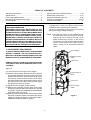
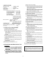
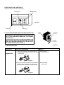
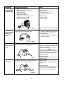
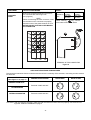
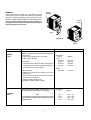
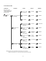
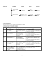
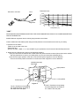
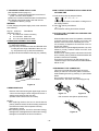
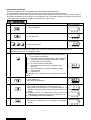
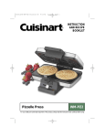
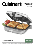
SERVICE MANUAL
Microwave Oven
EM-C1900 (GERMANY)
Pro.Code No.
437 623 01
Foreword
Model No.
EM-C1900SD
Read this manual carefully, especially precaution on microwave energy, and follow the procedure
strictly,careless servicing and testing may expose yourself to the microwave energy leakage.
PRECAUTIONS
PRECAUTIONS TO BE OBSERVED BEFORE AND DURING SERVICING TO AVOID POSSIBLE EXPOSURE
TO EXCESSIVE MICROWAVE ENERGY
(a) Do not operate or allow the oven to be operated with the door open.
(b) Make the following safety checks on all ovens to be serviced before activating the magnetron or other microwave
source, and make repairs as necessary:
(1)Interlock operation, (2) proper door closing, (3) seal and sealing surfaces (arcing, wear, and other damage),
(4) damage to or loosening of hinges and latches, (5) evidence of dropping or abuse.
(c) Before turning on microwave power for any service test or inspection within the microwave generating compartments, check the magnetron, wave guide or transmission line, and cavity for proper alignment, integrity, and
connections.
(d) Any defective or misadjusted components in the interlock, monitor, door seal, and microwave generation and
transmission systems shall be repaired replaced, or adjusted by procedures described in this manual before the
oven is released to the owner.
REFERENCE NO. SM-6410022-00
- TABLE OF CONTENTS Adjustment Procedures ............................................. 1
Specifications ............................................................ 2
Power output Measurement ....................................... 2
Precautions and Repair Service Tips .......................... 2
Circuit Diagram .......................................................... 3
Test Procedures and Troubleshooting ................... 4-10
Disassembly Instructions .................................... 11-14
Exploded View and Parts List ............................. 15-22
Overall Circuit Diagram......................................23-24
Control Circuit Board ................................................ 25
(6) Make sure the microwave energy leakage should be
no greater than 5 mW/cm2 to allow to measurement
uncertainty when measured with a detector.
(All service adjustments must be made for minimum
microwave energy leakage readings.)
CAUTION
MICROWAVE RADIATION
PERSONNEL SHOULD NOT BE EXPOSED TO THE
MICROWAVE ENERGY WHICH MAY RADIATE FROM
THE MAGNETRON OR OTHER MICROWAVE GENE
RATING DEVICE IF IT IS IMPROPERLY USE OR CONNECTED. ALL INPUT MICROWAVE CONNECTIONS,
WAVEGUIDE, FLANGES, AND GASKETS MUST BE
SECURE. NEVER OPERATE THE DEVICE WITHOUT
A MICROWAVE ENERGY ABSORBING LOAD ATTACHED. NEVER LOOK INTO AN OPEN WAVE GUIDE
OR ANTENNA WHILE THE DEVICE IS ENERGIZED.
NOTE: If the interlock monitor circuit operates and at
the same time the fuse blows with the door
opened, be sure to replace the relay circuit
board because relay 3 and 4 on the control
circuit board, the door sensing switch and the
electric circuit related on the door sensing
switch, which act as Secondary Interlock
switch.
1. ADJUSTMENT PROCEDURES
Lever stopper
NC
NO
C
TO AVOID POSSIBLE EXPOSURE TO MICROWAVE
ENERGY LEAKAGE, THE FOLLOWING ADJUSTMENTS OF THE INTERLOCK SWITCHES SHOULD BE
MADE ONLY BYAUTHORIZED SERVICE PERSONNEL.
PRIMARY INTERLOCK SWITCH, INTERLOCK MONITOR SWITCH AND DOOR SENSING SWITCH ADJUSTMENT
Interlock monitor
switch
Latch lever
(Figure 1)
NO
NC
(1) Loosen 2 screws securing the lever stopper.
(2) Adjust the lever stopper position so that it is pushed
up and pull backward until there is about zero gap
between the latch lever and the switch body on the
door primary interlock switch and the at the same
time there is about zero gap between latch lever and
the switch body on the door sensing switch when
the door latch is securely locked.
(3) Tighten the lever stopper screws securely.
(4) Make sure the interlock monitor switch closes after
the primary interlock switch opens the door is opened
very slowly, according to "CHECKOUT PROCEDURE
FOR SWITCHES" on page 6.
(5) Make sure the interlock monitor switch opens before
the primary interlock switch closes when the door is
closed very slowly, according to "CHECKOUT PROCEDURE FOR SWITCHES" on page 6.
Primary Interlock
switch
C
Latch lever
NO
NC
C
Door sensing
switch
Screws
-1-
Figure 1
(1) Before the power is applied.
(a) Open and close door several times to make sure
the door interlock switch and interlock monitor
switch operation properly. (Listen for the clicking sound from switches.)
Make sure the interlock monitor switch is closed
after the latch interlock switch is open when the
door is opened. (See pages 1 and 6)
(b) Make sure the perforated screen and the choke
dielectric of the door are correctly mounted.
(2) After the power is applied.
(a) Open and close the door to see if the interlock
mechanism operates properly.
(b) Check microwave energy leakage with a leakage detector and confirm the energy leakage is
below 5mW/cm².
(3) Do not operate the unit until it is completely repaired if any of the following conditions exists.
(a) Door is not closed firmly against the cavity front.
(b) The hinge is broken.
(c) The choke dielectric or the door seal is damaged.
(d) The door is bent or warped, or there is any other
visible damage to the oven that may cause microwave energy leakage.
Note: Always keep the seal clean.
(e) Make sure that there are no defective parts in
the interlock mechanism.
(f) Make sure that there are no defective parts in the
microwave generating and transmission assembly.
(especially wave guide)
(4) Following items should be checked after the unit
is repaired.
(a) The interlock monitor switch is connected correctly and firmly.
(b) The magnetron gasket on the magnetron is properly positioned.
(c) Wave guide and oven cavity are intact. (No leakage of microwave energy).
(d) The door can be properly closed and the safety
switches work properly.
(e) The oven must be stopped when the door is
opened or the time is up.
The oven must not be operated with any of the above
components removed or bypassed.
2.SPECIFICATIONS
Microwave output ................. 1,900W to 190W
Frequency ............................ 2,450MHz
Power supply ....................... 220-230V, 50Hz
Rated current ....................... 12.8 A
Safety Device .......................
Thermal limitter (Magnetron) 150°C Open
Thermal limitter (Duct)..........140°C Open
Thermistor (Magnetron) .... ...165°C Open
Thermistor(Duct) .............. ...120°C Open
Fuse (Cartridge Type) ...... ...250V 10A x2
Micro switch, Relay
Primary interlock switch
Interlock monitor switch
Door sensing switch and
Relay RL-3 and 4
Max. input time.......Electronic Digital,up to
Manual 10min.
Memory 6min.(power level 10-6)
30min.(power level 5-0)
Overall Dimensions ......... 422(W)x540(D)x335(H) mm
Oven cavity size .............. 330(W)x330(D)x230(H) mm
Effective Capacity of Oven Cavity..........19.1 liters
Net weight ............................ ...............32Kg
3. POWER OUTPUT MEASUREMENT
(1) Prepare 1000±5g tap water.
(2) Adjust water temperature to 10±2°C.
(3) Pour water into a container made of borosilicate
Glass, 190mm outer diameter cylinder, maximum
3mm thickness.
Note : Use the container kept on the room temperature.
(4) Place the container on the center of oven cavity.
(5) Set the heating time for 26 seconds and rating full
power and then start oven.
(6) Take the container out immediately when heating
time is up.
(7) Stir water for making even water temperature in
the container.
(8) Measure water temperature.
Water temperature rise shall be 8 to 12°C.
4. PRECAUTIONS AND REPAIR SERVICE TIPS
PRELIMINARY
HINT FOR LAMP CHANGE
Before removing the bulb access panel, pull out the
main plug. Change the faulty bulb and secure the bulb
access panel. Plug the cord back in and check operation.
A. SINCE NEARLY 4,000 VOLTS EXISTS IN SOME
CIRCUITS OF THIS MICROWAVE OVEN, REPAIRS SHOULD BE CARRIED OUT WITH
GREAT CARE.
B. TO AVOID POSSIBLE EXPOSURE TO MICROWAVE ENERGY LEAKAGE, THE FOLLOWING
PRECAUTIONS MUST BE TAKEN BEFORE SERVICING.
-2-
FUNCTION OF KEY SWITCHES
Please read each function key below.
Power Key
Memory Key
Start Key
Time Key
Clear Key
6. TEST PROCEDURES AND TROUBLESHOOTING
CAUTION
-DISCONNECT THE POWER SUPPLY CORD FROM THE
WALL OUTLET WHENEVER REMOVING THE CABINET
FROM THE UNIT.
PROCEED WITH TESTS ONLY AFTER DISCHARGING THE
HIGH VOLTAGE CAPACITOR AND REMOVING THE LEAD
WIRES ON THE PRIMARY WINDING OF THE HIGH VOLTAGE TRANSFORMER. (SEE FIGURE 2)
Primary
Winding
Filament
windings
Figure 2
A. TEST PROCEDURES
COMPONENT
MAGNETRON
Secondary
windings
CHECKOUT PROCEDURE
RESULT
1) Check for resistance: Across the filament
terminal of the magnetron with an ohm meter
on Rx1 scale.
Normal reading:
Less than 1 ohm.
Figure3
2) Check for resistance: Between each filament
terminal of the magnetron and the chassis
ground with an ohm meter on highest scale.
Figure 4
-4-
Normal reading:
Infinite ohms.
COMPONENT
HIGH-VOLTAGE
TRANSFORMER
CHECKOUT PROCEDURE
RESULT
1) Measure the resistance:
With an ohm meter on Rx1 scale.
a. Primary winding;
b. Filament winding;
c. Secondary winding;
2) Measure the resistance:
With an ohm meter on highest scale.
a. Primary winding to ground;
b. Filament winding to ground;
Figure 5
HIGH-VOLTAGE
CAPACITOR
Including bleeder
resistor
Measure the resistance: Across two terminals
with an ohm meter on highest scale.
Normal reading:
a. Approximately 1.0 ohms.
b. Less than 1 ohm.
c. Approximately 60 ohms.
Normal reading:
a. Infinite ohms.
b. Infinite ohms.
Note: Remove varnish of measured point.
Normal reading:
Momentary indicates several ohms,
and gradually to 10 meg-ohms.
Abnormal reading:
Indicates continuity or 10 meg-ohms
from the beginning.
Figure 6
HIGH-VOLTAGE
DIODE
Measure the resistance: Across two terminals
with an ohm meter on highest scale.
Figure 7
FUSE DIODE
Measure the resistance: Across two terminals
with an ohm meter on highest scale.
Normal reading:
Indicate about the middle position in
one direct ( forward ) and infinite ohms
in the reverse direction, using meter
with a 9-volts battery.
NOTE
- Some digital meter may show over
even in a forward direction because low
measuring voltage of meter does not
allow the meter to pass through the
high voltage diode.
Abnormal reading:
Indicates continuity or infinite ohms in
both directions.
Normal reading:
Indicate infinite ohms in both directions.
Abnormal reading:
Indicates continuity in both directions
or continuity in one direction and
infinite ohms in reversed direction.
Figure 8
-5-
COMPONENT
TOUCH KEY
BOARD
CHECKOUT PROCEDURE
RESULT
Measure the resistance between terminals of
FPC connector after removing it from
S101.(Figure 9)
NOTE
- When reconnecting the FPC connector, make
sure the holes on the connector are properly
inserted in hook of the plastic fastener in S101.
MATRIX CIRCUIT FOR TOUCH KEY BOARD
FPC CONNECTOR
When
Resistance touched
Less than
Value
1K ohms
A4
A5
A6
2
1
0
5
4
3
7
6
8
When checking “
”key, connect
ohm-meter as illustration below.
A1
A2
A3
A4
A5
A6
A7
A8
A9
9
A7
A8
A9
When not
touched
More than
1M ohms
+10
A1
A2
A3
TERMINAL OF FPC CONNECTOR
Figure 9
CHECKOUT PROCEDURE FOR SWITCHES
Disconnect the lead wires from the switches and check for the continuity of the switches, connecting an ohm-meter to
its terminals.
SWITCHES
(See Figure 1 on page 1)
CHECKOUT PROCEDURE
PRIMARY INTERLOCK
Terminals “COM” and “NO”
DOOR OPEN
DOOR CLOSE
0
0
0
0
DOOR SENSING
INTERLOCK MONITOR
Terminals “COM” and “NC”
CAUTION: After checking the switches, make sure that the interlock monitor switch is properly connected according to the “CIRCUIT DIAGRAM” on page 3.
-6-
Primary
winding
WARNING:
When removing the cabinet, you must disconnect the
power supply cord from the wall outlet for your safety.
Only the checkout procedure below needs the power
supply on. TAKE GREAT CARE to avoid possible shock.
For your safety, proceed with the test only after removing the wire leads from the primary winding of
the high voltage transformer.
Primary
winding
Lower
Figure 10
Upper
COMPONENT
CHECKOUT PROCEDURE
RESULT
POWER
P.C.B
Check each voltage at connector S104 and S105
after removing each connector (female) from power
circuit board.
Pin No.3 (Ground) and 4,5,1,2 at S105.
Pin No.1 and 2 at S104.
CAUTION:
Proceed with the test only after removing the
wire leads from the primary winding of high voltage transformer for your safety.
Test procedures:
a) Make sure that the power supply cord is not
plugged in.
b) Remove the connector S104 and S105 from
the power circuit board.
c) Plug the power supply cord.
d) And then, measure each voltage.
Measure the voltage: Between test points TP-1, TP-2
,TP-3 and ground. (See Figure 16 on page 25)
CONTROL
P.C.B
Note
- Proceed with the check of the control P.C.B to see if
any one of the measured values is different from the
specified values.
-7-
Normal reading:
Connection
Pin No.
S105
#3 to #4
#3 to #5
#3 to #2
#3 to #1
S104
#1 to #2
Test point
TP
TP-1
TP-2
TP-3
TP-4
Voltage
DC 12V
DC 16V
DC 30V
DC 35V
AC 2.4V
Voltage
DC - 5V
DC - 12V
DC - 16V
DC - 35V
B. TROUBLESHOOTING
CONDITION
TROUBLE
Power with normal
voltage is applied. Place
a cup of water inside
microwave oven
“
”,“ 1 ”,“ 0 ”,“ 0 ”
” keys
and “
are touched.
Fuse(10A) blows off
immediately
No display cooking time
Cooking operation
will not start
CHECK
RESULT
REMEDY
Step down
Transformer
Shorted
Replace
H.V Capacitor
Shorted
Replace
H.V Diode
Shorted
Replace
Connection of
FPC from Touch
key board
Incorrect
Reconnect
Power circuit
board
(See page 7)
Voltage
incorrect
Replace
Touch key
board
(See page 6)
Resistance
incorrect
Replace
Control circuit
board
(See page 7)
Voltage
incorrect
Replace
Door sensing
switch
(See page 6)
No continuty
Replace
Interlock switch
(See page 6)
No continuty
Replace
Control
circuit board
(See pages 7 & 25)
Voltage
incorrect
Replace
* Note:Oven will not accept settings of 60 through to 99 seconds.
TIME must be entered as 1 minute and 39 seconds for 99 seconds.
-8-
CONDITION
TROUBLE
CHECK
RESULT
Low microwave
output
Magnetron
Uneven heating
Rotation of top or
bottom antenna
REMEDY
Poor
oscillation
Replace
Gear motor
rotation has
stopped.
Repair or
replace
C. ERROR INDICATION
The Display will show an error indication for self diagnosis as follows.
"E" means that a service technician is required.
"U" means that user can correct the operation.
Display
E-21
Trouble
Thermistor (on duct)
senses a temperature of
120°C or higher.
Other Symptom
Oven stops heating.
Buzzer continuously beeps.
Blower motor will stop immediately.
Solution
Check and remove the cause of the cavity fire
or abnormal overheating.
This error function will be cancelled when the
power cord is unplugged.
E-31
Thermistor (on Magnetron
or Duct) is shorted.
Oven stops heating.
Buzzer does not beep.
Blower motor will stop
immediately.
Check for short-circuit of thermistor itself or
wire insulation of thermistor.
This error function be cancelled when the
power cord is unplugged.
E-32
Thermistor (on Magnetron
or Duct) is opened.
Oven stops heating.
Buzzer does not beep.
Blower motor is operated.
Check for open-circuit of thermistor itself or
improper connection of wire socket of thermistor.
This error function be cancelled when the
CLEAR key is touched.
U-10
Thermistor (on Magnetron)
senses a temperature of
225°C or higher.
Oven stops heating.
Buzzer continuously beeps.
Blower motor will stop
immediately.
Check and remove cause of abnormal overheating (such as operation with no food).
This error function will be cancelled when the
CLEAR key is touched.
The key for “
” is not
touched within 1 minute
after the door is opened
or closed.
(Remark:The purpose of this This error function will be cancelled when the
function is to avoid accidental door is opened and closed.
operation while the user is
not attempting to operate the
oven.)
U-50
-9-
1
2
3
Thermistor Chart
Duct
Magnetron
4
Resistance (K ohm)
Thermistor connector
8000
7000
6000
5000
4000
3000
2000
1000
0
0
10
20
30
40
50
60
Temperature (°C)
“HINT”
PROCEDURE FOR DETERMING WHETHER THE UPPER MAGNETRON CIRCUIT OR LOWER MAGNETRON
CIRCUIT IS DEFECTIVE.
SYMPTOM:One magnetron does not work giving less than normal heat.
Caution: Make sure that cabinet (outer wrap) and rear plate are not removed from the oven for your safety.
1.Operate oven as follows.
1)Place a cup of water in the oven
2)Close the door.
3)Touch “CLEAR”, “TIME”, “5”, “0” and “START” keys to operate the oven for 50 seconds with full power level.
2. Determine if the Exhaust air is warm in the following positions..
1)Put your hand near the exhaust duct outside of the rear plate to feel the exhaust (Never remove the cabinet
and rear plate from the oven for your safety when you put your hand near exhausting duct.)
2)If air from the upper position of the duct is not warm,the upper magnetron circuit is defective.
If air from the lower position of the duct is not warm,the lower magnetron circuit is defective.
Cabinet(outer wrap)
Rear Plate
Upper position
Rear Plate
Lower position
Exhaust Duct
Figure 11
The H.V Transformer for operating
the lower Magnetron is located on
the inside of the rear plate
The H.V Transformer for operating
the upper Magnetron is located on
the inside of the rear plate
- 10 -
7. DISASSEMBLY INSTRUCTIONS
interlock switch, the relay 3 and 4 (on the control circuit
board) and the interlock monitor switch according to
“CHECKOUT PROCEDURE FOR SWITCHES” on page
6. and make sure to check the microwave energy leakage according to “1. ADJUSTMENT PROCEDURE FOR
SWITCHES” on page 1, when the primary interlock
switch, the relay 3 and 4 or the interlock monitor switch
is adjusted or replaced.
- If the primary interlock switch, the relay 3 and 4 or the
interlock monitor switch operate properly, determine
which of the followings is defective : control circuit board,
blower motor, gear motor, high voltage transformer, high
voltage capacitor, high voltage diode or magnetron.
- If the high voltage diode is defective replace not only
the high voltage diode but also the fuse diode.
- OVEN MUST BE DISCONNECTED FROM ELECTRICAL OUTLET WHEN MAKING REPLACEMENTS, REPAIRS, ADJUSTMENT AND CONTINUITY CHECKS
BEFORE PROCEEDING WITH ANY REPAIR WORK
AFTER DISCONNECTING, WAIT AT LEAST 1 MINUTE,
UNTIL THE CAPACITOR IN THE HIGH-VOLTAGE
AREA HAS FULLY DISCHARGED.
A.REMOVING PRIMARY INTERLOCK SWITCH
(See Figure 1 on page 1)
(1) Disconnect all lead wires from the primary interlock switch.
(2) Remove 2 screws securing the lever stopper.
(3) Remove 1 screw securing the switches. Then pull
out the switches.
(4) Make necessary adjustment, and make microwave energy leakage check according to “1. ADJUSTMENT PROCEDURE FOR SWITCHES” and
page 1, after it is replaced with new one, and check
proper operation of it according to “CHECKOUT
PROCEDURE FOR SWITCHES” on page 6.
D.REMOVING DISPLAY CIRCUIT BOARD
(1) Disconnect all lead wires of the Control panel from
the Control PCB and Power PCB.
(2) Remove 3 screws securing the Control panel Assy
to the oven cavity.
(3) Push up and pull out the Control panel Assy.
(4) Remove 4 screws securing the Display PCB.
(5) Take out the Display PCB and push up the lever
end of the plastic fastener and remove the FPC
connector from the connector socket S101.
CAUTION:
When replacing new Display PCB please take big
care that all 10 LED heads should exactly be
inserted into the square holes of control frame all
at once. Never force to push any LED lead in the
PCB.
B.REMOVING INTERLOCK MONITOR AND DOOR
SENSING SWITCH
(See Figure 1 on page 1)
(1) Disconnect all lead wires from the interlock monitor switch and door sensing switch.
(2) Remove 1 screw securing the these switches.
Then pull out the switches.
(3) Make necessary adjustments or replacement of
switch by the reversing step (2) and check microwave energy leakage according to “1. ADJUSTMENT PROCEDURE FOR SWITCHES” on page
1, after it is replaced with new one, and check
proper operation of it according to “CHECKOUT
PROCEDURE FOR SWITCHES” on page 6.
E.REMOVING MAGNETRONS
(1) Remove 2 screws securing the thermal limitter.
(2) Disconnect 2 lead wires from the magnetron terminals by removing 2 connectors.
(3) Remove thermistor (lower magnetron) by pulling
horizontally.
(4) Remove 4 hex nuts (upper magnetron) or 2 hex
nuts (lower magnetron)securing to the waveguide.
(5) Remove lower magnetron.
(6) Take out the magnetron VERY CAREFULLY.
WHEN REPLACING ANY DOOR MICROSWITCH,
REPLACE WITH THE SAME TYPE SWITCH SPECIFIED ON THE PARTS LIST.
C.REMOVING FUSE
Remove the 10A fuse with screwdriver.
NOTES
- When replacing the 10A fuse, be sure to use an exact
repair part.
- If the 10A fuse blows immediately, check the primary
NOTES
- When removing the magnetron, make sure that its dome
does not hit any adjacent parts, or it may be damaged.
- When replacing the magnetron, be sure to install the
magnetron gasket in the correct position and be sure
that the gasket is in good condition.
- After replacing the magnetron, check for microwave
make sure the microwave energy leakage is below the
limit of the regulation (5mW/cm²).
- 11 -
F. CHANGING POWER SUPPLY CORD
(See exploded view on page 15)
(1) Unfasten 1 screw for earth and pull out 2 wires of
power cord from terminal plate.
(2) Remove 1 screw for bottom bracket of cord bushing.
(3) Install the new power supply cord with reverse
procedure of above (1) to (2).
WARNING:
For the changing the power supply cord, never use other
than following.
Key No. Order No.
(Mail body Parts-1)
5 617 208 1472
6 617 180 3211
20 617 140 1349
I.HOW TO RESET THE MEMORY OF ACCUMULATIVE
COOKING TIME
1. Push the keys step by step as follows,
“
”,“
”,“ 8 ”,“ 8 ”,“ 8 ”,“ 1 ”
“
”,“
”.
The display will show accumulative cooking time in
the display window.
2. Then push the keys as follows.
“ 0 ”,“ M ”
Accumulative cooking time will be cleared.
Parts Name
J.CAUTION FOR CUSTOMER ON OPENING AND
CLOSING DOOR
Power cord Ass'y
Cord bush
Bottom bracket
When the Microwave oven is in operation, should the
customer open the door slightly and close, the
breaker of the house will occasionally be cut off.
It is necessary to explain to the customer not to exercise such matter.
When the Door is opened slightly between 2 or 3mm
distance, primary interlock switch turn OFF, and
operation stops.
However door sensing switch will remain ON, and if
door is closed, primary interlock switch activates and
operation resumes immediately.
At such time microwave oven will start any time.
Therefore a big In-rush current flows, and thus breaker
will be cut off.
G. REMOVING CERAMIC TRAY ASS'Y
(See Fig.12 )
(1) Take off the cabinet.
(2) Put (insert) a screwdriver in the 9mm diameter hole
locating at lower hinge of left side of the oven cavity. And push the tray up with the screwdriver.
(3) Open the door and take out the tray very carefully.
Door
Hole
K.RELEASING TYPE CONNECTOR
This oven is provied with locked type connector.
When you remove a connector, pull the connector
while releasing the lock by pressing “A” point shown
below.
Do not pull the wire of the connector.
Connector:S1, S2, S102, S104, S105 (Figure 13)
Screw driver
Figure 12
H.REMOVING DOOR
Remove 3 hex nuts securing the upper hinge, remove
3 hex nuts securing the lower hinge and remove 1
special screw securing the door arm
(located at the bottom of the door sash).
Figure 13
Figure 14
Pull connector case (Never pull the wire)
NOTES
- After replacing the door, be sure to check that the
primary interlock switch, the door sensing switch and
the interlock monitor switch operate normally.
(See pages 1 and 6)
- After replacing the door, check for microwave energy
leakage with a leakage detector. Microwave energy
leakage must be below the limit of 5mW/cm².
Figure 15
- 12 -
L. ADDITIONAL FUNCTIONS
The following functions can be completed by the key operation described below.
The Accumulative cooking time and the number of door opening/ closings can be observed.
The Type and level of the buzzer sound can be selected. The “display of remaining cooking time when cooking is
temporarily stopped due to door opening” can be selected. The “Accumulative cooking time period” will inform the
service technician of the life expectation of the magnetron or other parts.
OPERATION
KEY
1
• Press CLEAR key.
2
• Press TIME key.
3
8
8
8
DISPLAY WINDOW
• Press 8 three times.
Key operations at Step 1 thru Step 3 are common to all functions. Proceed with the key
operation at Step 4 for your desired functions.
• Select the function to press the number key listed below.
1
4
5
6
7
1 ... Accumulative cooking time.
2 ... The number of door operations. (See “HINT” at Step 6)
3 ... Indication of remaining cooking time (when cooking
is interrupted by door opening).
4 ... To cancel remaining cooking time.
5 ... Tone of the buzzer on cooking completion. (Pip,
Pip, Pip)
6 ... Tone of the buzzer on cooking completion. (Peep)
7 ... The buzzer off.
8 ... The buzzer on.
e.g. Number 1 key is pressed for “Accumlative cooking time
period”
• Press START key.
• All 4 digits will be flashing.
• Press START key again.
• The number “215”shows total cooking time in hours.
• When number key other than 1 or 2 is pressed at step 4, “0”
appears in display window and the setting has been completed.
Note:When number “2” is depressd at Step 4 above the
displayed figure shows the number of door operation÷100
e.g. “20” displayed=2000 door operations.
• Press CLEAR key to clear the display for the option 1 and 2.
• The function is cleared and “0” will appear in the display
window.
- 13 -
Maintenaunce:
The microwave ovens are designed, manufactured, and tested for years of dependable operation. Howevre, the
oven may require service from time to time if the consumable components listed below are not replaced at the
appropriate time. For protection from unexpected service calls and undue inconvenience, we recommend that
the user has the listed parts replaced at the intervals belows,(at customer cost).
This will avoid the trouble of repeated service calls after the expiration of the warranty period.
Consumable components:
When more than 1,250 hours of accumulative cooking time or more than 200,000 cycles of door opening/closing
is observed by key operations (See page 13 for more information), the following consumable components shoud
be replaced.
(Maintenance light in window display indicates when accumulativ cooking time reaches 1,250 hours.)
Light
1. Magnetron Tubu, Part No. 415 003 1709 (Page 20 : No 2)
2. Printed Circuit Board-Relay, Part No. 617 202 0150 (Page 17 : No 25)
3. Switch base Assembly, Part No. 617 206 7865 (Page 20 : No 7)
4. Door Latch, part No. 617 068 1087 (Page 21 : No 16)
When more than 2,000 hours of accumulative cooking time is observed, the following consumable components
should be replaced.
5. Blower motor, Part No. 617 196 9245 (Page 20 : No 1)
When slow rotating of blower motor is observed after removing dust from blower motor, blower motor must
be replaced.
6. Door hinge, Part No. 617 120 3028 (Page 21 : No 11)
When a worn door hinge is observed and proper door adjustments can not be made, the door hinge must
be replaced.
7. Door Assembly, Part No. 617 239 6354 (Page 21 : No 8)
When a worn door pin is observed and proper door adjustments can not be made, the door assembly must
be replaced.
- 14 -