1
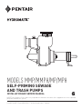
MODELS MMP/MMPH/MP/MPH SELF-PRIMING SEWAGE AND TRASH PUMPS INSTALLATION AND SERVICE MANUAL NOTE! To the installer: Please make sure you provide this manual to the owner of the equipment or to the responsible party who maintains the system. Item # E-03-353 | Part # 5625-353-1 | © 2014 Pentair Ltd. | 12/04/14 General Information The MMP/MMPH/MP/MPH selfpriming centrifugal pump has a semi-open impeller and suction flap valve. Pump is designed to handle raw unscreened sewage, mild industrial waste and slurries containing entrained solids. The material of construction is a cast iron volute case and bearing frame, ductile iron impeller and wear plate. General Information: This manual contains important information for the safe use of this product. Read this manual completely before using this product and refer to it often for continued safe product use. Unpacking Pump: Remove pump from pallet. When unpacking unit, check for concealed damage. Claims for damage must be made at the receiving end through the delivery carrier. Damage claims cannot be processed from the factory. Check for and tighten all loose attaching hardware. Check oil levels and lubricate as necessary. WARNING: Before handling these pumps and controls, always disconnect the power first. Do not smoke or use sparkable electrical devices or flames in a septic (gaseous) or possible septic area. CALIFORNIA PROPOSITION 65 WARNING: This product and related accessories contain chemicals known to the State of California to cause cancer, birth defects or other reproductive harm. Pump Not Operating or in Storage: If pump is not put into service immediately, it must be properly stored to prevent damage. Store unit in a dry warm location. Never store unit in the open even if it is protected with plastic or other covering. The bearing housing and motor will draw moisture, which may result in pump failure after being put in operation. 2 While in storage pumps with carbon ceramic seals must have impellers manually rotated (6 to 12 revolutions) after setting nonoperational for 3 months or longer and prior to electrical start-up. Pumps with tungsten carbide seals must have impellers manually rotated (6 to 12 revolutions) after setting non-operational for 3 weeks or longer and prior to electrical start-up. Motors: Pump unit may be shipped less the motor for customer to supply and mount. Motor Types: Pumps can be driven by standard drip-proof, totally enclosed fancooled, totally enclosed hazardous location or drip-proof motor with encapsulated windings for moisture protection. If motor is to operate in the open or in a dusty location, a totally enclosed fan-cooled motor must be used. If pump is to operate in a damp location, a motor with encapsulated winding should be used. Motors are to be sized so that no overload will exist in the operating range of the pump. Note: When pump units are mounted at the factory, the driver and pump are aligned before shipment. During transit and handling of pump and components, misalignment may occur. Before operation the drive alignment should be checked. Shaft Couplings: We recommend using Wood’s flexible coupling to prevent misalignment and noise that can be caused by other couplings. The extra cost of the coupling is easily saved in installation and field service that can result from coupling problems. V-belt Drive: Where V-belts are used, keep belts tight by adjusting motor base screws. Belts should run cool. If belts heat up, it indicates slipping. The V-belts should be fiddlestring tight. CAUTION: Belt guards and coupling guards must be properly installed before operating pump unit. Electrical Starting Equipment: If electrical starting equipment is not furnished with pump, certain precautions must be observed in selecting motor starter. Type of Starter: For three phase power a magnetic starter with 3-leg overload protection is recommended to prevent motor burnout that can occur from single phasing or transformer faults on three phase systems. For single-phase motors a standard starter with 2-leg overload protection is recommended. Electrical: 1. For motor overload protection the magnetic starter trip amp rating should not be more than 1.25 times the full load amps of the motor. Hydromatic® recommends a rating of 1.15 times the full load amps of the motor. 2. Always use fused disconnect switch or circuit breaker ahead of magnetic starter for short circuit protection. When duplex pumps are used and are operated from single disconnect switch, be sure disconnect switch is large enough to withstand the starting current of both pumps coming on at once. This can occur after a power failure. This is important as a blown fuse or tripped circuit breaker can make both pumps and an alarm system inoperative, resulting in flooding or other damage. Ground: Connect a ground wire to motors, control box and other related controls. Ground wire is to be sized to the National Electric Code article 250-95. Ground wire must be connected to a driven ground stake or to a ground wire from the supply service. If a ground stake is used, it must be driven at least 8 feet into the ground. Codes: All local wiring codes must be observed, and any exceptions to data given must be followed in accordance with the local code. Consult the local inspector before installation to avoid costly delays. Pump Installation Pump Installation Foundation: Pump frame or base should be installed on a concrete floor with proper shims and grout. Use hardwood tapered shims to drive under base to level. Base should be about 1 to 11/2" off the floor. Build form around the base and fill base inside cavity with grout. Foundation bolts can be set in the grout or set in the concrete floor with expansion bolts. Grout should be made with 1 part cement and 2 parts sand. Mixture should be fluid enough to run under base. Wood shim blocks can be removed after grout has set and holes filled with quick set cement. Piping: All piping to suction and discharge openings of pump must be supported to remove stress from the pump case and bearing frame. Suction Pipe: 1. Suction pipe should be the same size as pump opening. Do not use larger suction pipe as priming time will be increased and velocity may not be high enough to properly carry solids. 2. Pump should be installed as close to the liquid being pumped as possible with a minimum of elbows or fittings. 3. To avoid air pockets, suction pipe must be as short and direct as possible. Suction pipe must always slope upward to the pump from the source of the liquid being pumped. 4. The suction pipe should be installed at a distance equal to 11/2 times the diameter of the suction pipe from the wall of the wet well, minimum. 5. The suction pipe should be installed at a distance equal to one half the diameter of the suction pipe or 3" from the floor of the wet well, minimum. 6. If more than one suction pipe is to be installed in the same wet well, a distance equal to at least 3 times the diameter of the suction pipe should separate them, minimum. 7. Submergence of the suction pipe is critical to efficient pump operations. Submergence may be reduced by installing a standard pipe increaser fitting at the end of the suction pipe. The larger opening size will reduce the inlet velocity and required submergence. Vertical Suction Lift: Vertical lift should not be more than 25 feet for MMP/MMPH models and not more than 15 feet for MP/ MPH models. This is for starting level only. After pump primes, level can be pumped down to 26 to 27 feet for MMP/MMPH models or 18 to 20 feet for MP/MPH models, if desired. But sump level must rise up to the original level for restart. All suction line joints must be airtight as a leak in the suction pipe can cause the pump to lose prime or not prime at all. Always check NPSH calculations for available atmosphere pressure before applying pump. Discharge Lines: If the discharge line ends at level lower than the liquid being pumped, a siphon breaker must be installed in the discharge line. Otherwise, siphoning action may cause damage to the pump. The discharge line should include a system check valve, with outside weight or spring, to protect the pump from excessive shock pressure and reverse rotation when pump is stopped. Do not depend on the check valve at pump suction to hold discharge pressure. The discharge line should include an isolation valve, plug valve or gate valve, to isolate the pump from the discharge line. This will allow maintenance to be performed on the pump or check valve without draining the discharge line. Air Bleed Pipe: A 3/4" or 1" bleed line with ball valve or gate valve must be installed between the pump discharge flange and discharge check valve. The bleed line should be installed as close to the discharge check valve as possible, the end extending a minimum of 6" below low water offset point in the wet well. The valve in the bleed line is to be fully open at initial start-up of pump. After initial start-up the valve is to be left partially open at all times. This will allow any trapped air or gas to be vented back to the wet well. Be sure vent line is under water at all times. This is important. Selfpriming pumps will not compress air to any extent. Pump may not prime if the bleed line is not used or closed and may not reprime if pump loses prime after discharge line is full of water and a discharge check valve is used. Drain Line from Pump Case: A pipe should be installed in the lower drain tapping of volute case and be piped back to the wet well. Install a shut-off valve, ball valve or gate valve in this line. This will permit draining of pump case if necessary to remove suction elbow/ plate to clean impeller or perform maintenance on the pump. Electrical Connections: Connect power lines to motor from magnetic starter. Turn pump shaft by hand to be sure it is free before attempting to start motor. Turn power on and off quickly to check rotation. If motor is three phase, interchanging any two lines to motor can reverse rotation. If motor is single-phase, consult literature supplied with the motor for specific instructions. Correct pump rotation is clockwise when looking at pulley or coupling end (power end) of pump. Direction arrow is cast on bearing housing. 3 Priming: For initial prime, remove priming cap from suction inlet casting and fill pump housing with water. Fully open the air bleed valve in the bleed line. Replace cap, being sure gasket is in place and that seat is clean. Start motor and allow sufficient timing for priming. Priming time is dependent on pump speed, impeller diameter and vertical suction lift. Cleaning Impeller: If impeller gets clogged at any time, suction elbow/plate can be removed by unscrewing 4 hand knobs or nuts. Drain pump case before removing suction elbow/plate. Tap on knobs with hammer to loosen. Be sure O-ring gaskets are in place before replacing suction elbow/plate. Use grease on machined faces to make removal easier at a later date. Tap on hand knobs with hammer to retighten. Adjusting Impeller Clearance: Flapper Valve, Suction Inlet, Priming Port Housing: When the pump is empty, the flapper valve rests loosely against the inlet flange of the suction inlet. Before the initial start, the priming port/cap is opened and the pump filled with water. The discharge should be vented and water should fill both suction and discharge chambers. When completely full, the suction flap valve will press against the suction inlet flange and no water should leak down into the sump. Just before the pump is engaged and turned for the first time: 1. Both suction and discharge chambers are filled with clean fresh water. 2. The suction flap valve is pressed tightly against the inlet flange with the water that now fills the priming port housing. Impeller face vanes must be within .015" of suction wear plate for most efficient operation. 3. The vacuum gauge registers zero. When wear plate or impeller wears, it can be readjusted to proper clearance from the outboard bearing end without the use of shims or disturbing the pump case or piping. Loosen the three screws with the jam nuts. Tighten the other three screws evenly until the impeller just drags on the suction wear plate when the shaft is turned by hand. Back off the three screws and place a .015" shim under the head of the screw. Turn screw up against the shim, then remove shim. Repeat this operation on each of the three pushing screws. Now retighten the three screws with jam nuts, pushing the housing up against the three adjusting screws. Retighten the jam nuts and pump is ready to operate with the impeller face .015" from suction wear plate. Just after the pump turns on and the impeller has revolved 8–15 times, some of the water in the pump has been: This clearance should be checked at least once a year and more often if water containing abrasives is being pumped. When impeller face wear exceeds 1/8", impeller, wear plate and volute lip plate should be replaced. 4 4. The suction pipe into the wet well is empty. 1. Pumped into the discharge pipe and possibly through the discharge check valve. 2. Vented through a ¾ inch discharge vent, back into the sump. 3. Internally recirculated back to suction. As the pump continues to run, air is vented and water recirculated, and a partial vacuum is generated. The function of the flapper valve, therefore, is to vent the partial vacuum created in the suction volute to the suction line. This allows atmospheric air pressure to push sump water up through the suction line into the pump. Pump Lubricating Shaft Seals: All Hydromatic self-priming sewage pumps use two shaft seals with an oil chamber between the seals. The oil in the seal chamber should be checked every six months or every three months if water containing abrasives is being pumped. Remove hex head plug from top of seal chamber and loosen hex plug at bottom of seal chamber. Place a container under the lower plug, then remove lower plug and allow oil to drain into container. After all oil is removed, pour used oil into a glass container so that it can be observed. If the oil is clean it will indicate seals are in good condition. If a small amount of water shows in the oil, this will also indicate satisfactory seal operation. If considerable water and some dirt show in the oil, it will indicate the inboard seal is worn and should be replaced before outboard seal is damaged. If seals are in good order, refill the seal chamber with #30 nondetergent automotive oil. About 21/2 quarts are required for MMP/MMPH models and about 1 quart for MP/ MPH models. Fill with funnel or tube so that the air can escape. Oil chamber must have a 1" air gap; do not overfill oil chamber. Pump Bearings Grease Lubricated: Bearings should be lubricated every six months or more often if pump is operated 24 hours a day. Do not overgrease bearings as heat will build up that can damage the bearings. Bearing housing is fitted with grease gun pressure fittings at both bearing locations and grease relief fittings. Add grease until a small amount comes from relief fitting. The same basic instructions apply to lubricating motor bearings, but consult motor manufacturer’s data on lubricating bearings. Use high quality ball bearing grease or high temperature grease. Bearings can run quite hot to the hand without damage to the bearing. Outside temperature of the housing should not exceed 130° F for long bearing life. Pump Maintenance Replacing Impeller and Volute Lip Plate: Disconnect power from the motor before attempting to work on pump. Drain pump volute case and oil from seal chamber. Remove suction elbow/plate with wear plate attached. Clean any trash out of pump volute, clean all machined surfaces and wipe all ports clean. The following pertains to the 3" and 4" pumps. Remove stainless steel socket head impeller screw that locks impeller to the shaft. This screw has a right-hand thread. Remove impeller lock washer with pin. Block impeller vane with a piece of hardwood and unscrew impeller by turning pump shaft counterclockwise. Impeller shaft has a right-hand thread. Use large crescent wrench or strap wrench on shaft, pulling against the key. A pipe wrench can be used if care is used not to damage shaft. It may be necessary to tap on impeller vanes with hammer to break impeller loose, especially if pump has been in service for a long period of time. If impeller is held to the shaft with a taper fit, remove the stainless steel nut on the end of shaft, then remove washer. A taper fit shaft can be identified by the key that drives the impeller. To remove impeller, loosen 3 holding screws at outboard bearing cap and tighten up on back-off screws. This will pull the impeller loose from the shaft. After impeller is removed, retighten screws to bring bearing cap back to original position. It will be necessary to readjust the impeller clearance after impeller is reinstalled. After impeller is removed, unscrew 3 or 4 stainless steel socket head screws that hold volute lip plate in place. Tap on plate to loosen and remove through volute case inlet opening. The inboard seal now can be removed for inspection by sliding sleeve from pump shaft. If faces are worn, the seal should be replaced. Clean pump casing thoroughly, removing any rust or dirt from all machined surfaces. Install lip plate with lip in the one o’clock position. Use a pipe compound on all machined faces. The following pertains to the 3" and 4" pumps. Use Permatex®* on the three stainless steel screws that hold volute lip plate in place. Reinstall the lip plate and tighten the screws. Install seal on shaft and place seal spring in place. Block impeller vane with a piece of hardwood and screw impeller on by turning pump shaft clockwise. Use large crescent wrench or strap wrench on shaft, pulling against key to retighten. A pipe wrench can be used if care is used not to damage shaft. Replace impeller lock washer with pin and stainless lock screw. All 6", 8" and 10" pumps, use a taper fit impeller shaft. Use Permatex® on the four stainless steel screws that hold volute lip plate in place. Reinstall the lip plate and tighten the screws. Install seal on shaft and place seal spring in place, then install key and impeller. Caution must be taken to be sure impeller is seated on the shaft and not on the key. Replace impeller lock washer and stainless lock bolt. Replace suction elbow/plate with wear plate attached. Check impeller clearance and adjust if necessary as described under Adjusting Impeller Clearance. Refill seal chamber as described under lubricating instructions. Replacing Inboard Seal: Use all steps outlined under impeller removal. Slide seal and shaft sleeve from shaft. It may be necessary to tap on sleeve with plastic hammer to loosen. After rotating part of seal is removed, use wire hook and pull stationary seal seat from casting. Wipe seal pocket clean, then install new stationary seat. Use grease on rubber cap and push in place with fingers, then wipe the seal face clean. Place new rotating seal part on sleeve and to push sleeve onto shaft. Be sure O-ring gasket is in place at end of stainless steel shaft sleeve. Reinstall volute lip plate, put seal spring in place and install impeller. Install impeller washer, impeller lock screw or nut, and suction elbow/plate. Check impeller clearance, and adjust if necessary as described under adjusting instructions. Refill seal chamber with #30 nondetergent automotive oil. Replacing Both Inboard and Outboard Seals: When it is necessary to replace both seals, which will be indicated by water leaking from the seal chamber, it is recommended that the complete rotating assembly be removed so that it can be worked on more easily. Drain pump and seal chamber as described above. Then loosen or remove the pump coupling or remove V-belt components, if belt driven. Remove motor bolts and move motor to one side. Remove bolts in bearing bracket support foot and remove six nuts from studs in seal housing. Tap on housing with hammer to loosen, then pull complete assembly from case. Remove impeller and lip plate; see Replacing Impeller and Lip Plate. Remove inboard seal by sliding sleeve from shaft. Use two screws in tapped holes of seal plate and pry out plate with pinch bar under heads of pull bolts. Remove snap ring from shaft and pull outboard rotating assembly from shaft. Use wire hooks to pull ceramic stationary seal seat from housing. It may be necessary to break the ceramic seal ring. Ceramic ring can be easily broken by tapping with screwdriver. Ring is broken only if worn and needs to be replaced. Wipe housing clean and replace ceramic stationary ring. Use grease on rubber cap to push into housing. Push in stationary seal seat with fingers only, then wipe the seal face clean. Push new rotating seal part onto shaft. Replace seal spring and holding washer, then install snap ring. Replace seal plate. Be sure O-ring is in place and that flat rubber gasket is in place on backside of seal plate. Use grease on O-ring and push plate into position in seal housing. 5 Replace the three socket head stainless steel screws. Use Permatex on bolt threads. Replace new inboard stationary seal face. Now replace rotating seal part mounted on shaft sleeve. Replace volute lip plate with the three or four socket head stainless screws. Use Permatex on screw threads. Install seal spring and then screw impeller onto shaft. Lock impeller on with washer and stainless steel socket head screw. If shaft has a taper fit, be sure key is in place and in notch of shaft sleeve. Unit is now ready to reinstall in casing. Use a pipe compound on machine faces and be sure case O-ring is in place on flange. Replace nuts and bearing bracket support foot. Reset motor and connect coupling or reinstall belts if unit is belt driven. Refill seal chamber with #30 nondetergent automotive grade oil. Replace top fill plugs. Replacing Shaft Bearings: Both inboard and outboard shaft bearings are single row type and are the same size for any given pump. Grease lubricated bearings are single shield. To replace bearings, remove the impeller, seal plate and seals as described previously. Remove holding screws from outboard bearing cap and pull shaft and bearing assembly from housing. It may be necessary to tap on end of shaft with plastic or rubber hammer to loosen shaft bearings from housing. After shaft is removed take snap ring off end bearing cap and push shaft and bearing from housing. Use arbor press to press bearings from shaft. Always support or press on inner face of bearing. Never press on outer face as this can damage the bearing. Be sure housing and all parts are thoroughly cleaned before installing new bearings. Use care in pushing shaft through lip seals that seal shaft in bearing housing and bearing cap. Clean all old grease from housing and cap and pack bearing level full with grease before reinstalling. Do not add any extra grease to housing after assembly, as this grease pack is sufficient for at least 6 months usage. After shaft is reassembled, 6 install seals and impeller and adjust clearance of impellers as described previously. Pump Troubleshooting WARNING: If pump has overheated, allow pump to cool before servicing. Do not remove plates, cover, gauges or fittings from an overheated pump. Liquid inside the pump case can reach the boiling point, and vapor pressure within the pump case may cause parts to be ejected with great force. Drain pump case only after pump has been allowed to cool. Use care to prevent personnel from touching the hot liquid. Pump will not prime: 1. Pump discharge does not have air bleed line installed. See pump installation instructions for air bleed line. 2. Vertical suction lift is too high. Vertical lift for priming should not be more than 20 feet (MMP/ MMPH) and 15 feet (MP/MPH). 3. Allow sufficient time for priming. On high lifts and at low pump speeds priming time may take 5 minutes or longer. 4. Suction line has an air leak. Install a vacuum gauge at pump suction flange and start pump. After a vacuum is established, stop pump and see if gauge holds. If gauge hand drops, it will indicate an air leak at some connection below the gauge tap. 5. Check pump rotation. Pump must turn clockwise when looking at the power end of pump. 6. Not enough liquid in pump casing; add water to the case. Pump needs water in the pump case to prime. 7. Suction check valve damaged or contaminated; replace check valve. 8. Leaking or worn seal or pump gasket; check pump case vacuum; replace leaking or worn seals or gaskets. Pump primed OK initially but occasionally loses prime and will not reprime without adding water: IMPORTANT: Drain pump case and close discharge gate valve before removing the inspection cover. 1. Air bleed line is not installed properly as specified or is plugged. 2. Check priming port for plugging. Remove inspection cover on right side of case when facing power end of pump. Check priming port hole in case below inspection plate for plugging. 3. Impeller may be worn, leaving too much clearance between impeller face and suction wear plate. Adjust impeller as described under adjusting instructions. If impeller and volute lip plate are worn, they must be replaced to regain original priming efficiency. Pump makes a loud crackling noise when operating: 1. If pump has been operating satisfactorily and this noise suddenly starts, it may indicate that some large object is lodged in the suction check valve, suction elbow/plate or impeller causing the pump to be noisy. Remove debris from these areas of the pump. 2. If noise exists when suctioning pipe, check to see if valve and suction elbow are clear. It may indicate too high a capacity is being delivered for a given suction lift, causing suction cavitation. If pump is allowed to operate under these conditions, the impeller will be damaged. Using a smaller impeller or reducing the pump speed if a belt drive is used may alleviate the cavitation. Consult factory for recommendations. 3. If cracking noise is pronounced when pump is operating at low capacity it may indicate pump is operating too near the shut-off head. Increasing the impeller diameter or increasing pump speed may alleviate this condition. Consult factory for recommendations. 4. Performance curves show maximum / minimum capacity that the pump will deliver at a given condition point and the allowable suction lift without cavitation. Use vacuum gauge at pump suction to check total suction lift when pump is operating. Use discharge pressure gauge at pump discharge to check discharge head. Total the two-gauge reading to determine the total dynamic head the pump must operate against. 5. Entrained air may be present and is being pumped. Find source of air and eliminate. 6. Pump or drive not securely mounted. Retighten all components. Pump does not deliver rated capacity: 1. Total head may be higher than calculated. Pump capacity is based on total head. Total dynamic head is arrived at by adding the suction gauge reading, in feet, to the discharge gauge reading, in feet. These readings should be taken at the suction flange and at the pump discharge flange connections. Reading should be taken as close to the flange fittings and pump case as possible. To convert psi, pressure per square inch, to feet, multiply the total psi readings by 2.31. This will equal total dynamic head in feet. 2. Pump impeller may be worn on the vane faces or the clearance between the impeller and wear plate may be greater than .015". Adjust impeller to wear plate clearances for proper clearance as described under Adjusting Impeller Clearance. If impeller, suction wear plate and volute lip plate are badly worn, they must be replaced. 3. Pump speed may be too slow. Check drive assembly, V-belts or coupling, for slippage. 4. Possible air leak in the suction piping; eliminate the leak. 5. Suction head may be too high. Reduce lift by raising on /off levels in the wet well or reduce friction losses due to suction piping arrangement. Bearing running too hot: 6. Suction line not submerged at proper levels; correct suction pipe submergence. 3. Suction and/or discharge pipe not supported properly. Check piping installation for proper support and take strain off the pump case and bearing frame. 7. Blockage in the suction pipe or discharge pipe; remove blockage. Where the blockage is can be determined by gauge readings. 1. Drive misaligned; realign drive. 2. Low or incorrect lubricant; use proper type and level of lubricant. 8. Impeller clogged; remove debris. Motor starter overload trips after pump has operated for a short period: 1. Rags or trash may be caught in the impeller, causing extra load. Remove suction elbow/plate and clean impeller. Pump shaft must turn freely by hand after cleaning impeller. 2. Overload heater may be too small. Check heater size with full load amps of motor. 3. Total head may be lower than calculated, causing extra load on the motor. Reducing impeller diameter or reducing speed if belt driven, will lower motor load. Consult factory for recommendations. 4. Pump may be pumping a liquid heavier than water or a liquid with higher viscosity than water, such as heavy oil. Consult factory for power required to pump oils or liquids other than water. 5. Bearings may be damaged, causing excessive motor load. 6. Pump speed may be too high. Check drive output to see if they are sized properly. Pump clogs frequently: 1. Liquid solution being pumped is too thick; dilute if possible. 2. Discharge velocity too slow. Open discharge valves to fully open and increase pump speed. * Permatex® is a registered trademark of Permatex, Inc. 7 30MMP Parts List Item Eng. No. Part Description Qty. Item Eng. No. 1 134840001 Sleeve 2 32 057600002 2 120140011 Piston Cup 3 020490002 Suction Flange 3" x 4" Qty. Item Eng. No. Part Description Qty. Lip Plate 8-13/32" Dia Imp 1 50 010650013 Support Foot 1 1 1 042280032 Lip Plate 7-7/8" Dia Imp 1 51 05454A004 Lockwasher 4 042280022 Lip Plate 7-1/2" Dia Imp 1 52 100-012112-273 Bolt 4 120110001 Bracket, Flap 2 1 042280012 Lip Plate 7" Dia Imp 1 53 19102A012 Bolt 5 131230021 Screw 1 032430032 Lip Plate 6-1/2" Dia Imp 1 54 010900011 Lip Seal 6 013420002 Suction Flange 3" x 3" 1 032430022 Lip Plate 6-1/4" Dia Imp 1 55 041300001 Shaft 1 7 009050022 Clamp Handle 2 33 005680021 Impeller Bolt 1 56 009750041 Snap Ring 1 8 05454A005 Lockwasher 14 34 010390001 Impeller Washer 1 57 062050001 Grease Fitting 1 SC Part Description 2 9 010850011 Nut 17 35 001780011 Capscrew 3 58 010660002 Bearing Cap 10 010790021 Stud 10 36 009050002 Clamp Handle 4 59 001500131 O-ring 11 120110105 Flap Valve Assy – Piston Cup 1 37 010240011 Stud 4 60 010640002 Bearing Housing 12 010270021 Stud 2 38 001500231 O-ring SC 2 61 052180001 Grease Fitting Straight 13 010750012 Weight 1 39 001500211 O-ring SC 1 62 015090021 Shaft Sleeve 14 010300081 Stud 2 40 010600002 Wear Plate 1 63 009010002 Seal Plate 1 15 127-058011-243 Nut – Hex 5/8-11 2 41*** 010610042 Impeller 8-13/32" Dia 1 64 010630012 Seal Housing 1 16 05454A011 Lockwasher 2 010610052 Impeller 8-3/16" Dia 1 65 016640011 Pipe Plug 2 17 002410061 O-ring 1 010610062 Impeller 7-7/8" Dia 1 66 001500191 O-ring 18 041270002 Discharge Flange 1 010610072 Impeller 7-1/2" Dia 1 67 041230002 Volute Case 1 19 120090003 Priming Cover 1 011720032 Impeller 7" Dia 1 68 001560591 Washer 1 20 120150001 Cover Gasket 1 011720042 Impeller 6-1/2" Dia 1 69 045800011 Drivescrews 4 21 001560471 Washer 1 011720052 Impeller 6-1/4" Dia 1 70 010240051 Stud 2 22 119990002 Suction Box 1 011720132 Impeller 6-3/4" Dia 1 71 19109A030 Nut 2 23 120130001 Gasket 3 72 001180011 Pipe Plug 2 24 001190011 3 73 041290002 Discharge Flange 3" x 4" 1 25 010770002 3 74 010240021 Stud 2 26 1 75 041280002 Discharge Flange 3" x 3" 1 SC SC SC SC 1 SC 1 1 1 SC SC 1 1 1 42 011330011 Gasket Pipe Plug 3 43 001780061 Capscrew Suction Flange 1 44 029220011 Stat-O-Seal 001200011 Pipe Plug 1 45 009750031 Snap Ring 27 000790071 O-ring SC 1 46 009200011 Seal (Ceramic) Std. SC 2 76 010790091 Stud 4 28 002410041 O-ring SC 1 009200041 Seal (Carbide) Opt. C 1 77* 19109A013 Nut 1 29 045120002 Inlet Elbow 1 47 013450001 Relief Fitting 2 78 052190001 Grease Fitting Cap 2 30 025830011 Pipe Plug 1 48 000650071 Bearing 2 79 001560491 Washer 3 31 19101A003 Bolt 2 49 009740021 Snap Ring 1 80 517280005 Flap Valve Box Assy 1 517000387 Seal Kit 1 517003387 Carbide Seal Kit 1 Notes: S — Parts in Seal Kit C — Parts in Carbide Seal Kit *Consult Factory ***Impellers cannot be trimmed. Trim sizes must come from the factory. 8 6 SC SC 30MMP Parts 76 9 8 3 72 7 73 26 74 71 51 6 75 26 74 71 51 14 15 16 17 18 51 71 70 25 24 20 12 19 22 67 69 1 11 4 5 66 21 68 23 64 13 28 37 36 65 77 63 2 8 9 10 61,78 61 54 60 59 48 58 9 53 78 57,78 56 31 32 55 33 54 47 34 30 53 52 29 51 50 49 24 38 24 12 39 40 41 35 43 42 8 2 1 13 77 47 48 41 32 4 19 9 9 10 62 27 45 46 20 4 21 77 1 5 68 68 21 Flat back plate used with full dia. impeller 43,44,79 2 76 23 80 13 11 9 40MMP Parts List Item Eng. No. Part Description Qty. Item Eng. No. Part Description Qty. Item Eng. No. 1 19101A003 Cap Screw 2 30 009240011 Pipe Plug 1 54 008980002 Bearing Housing 1 2 001500231 O-ring 1 31 001500241 O-ring 2 55 052180001 Grease Fitting Straight 1 3 000790071 O-ring 1 32 008910002 Wear Plate 1 56 005680041 Impeller Bolt 1 4 052190001 Grease Fitting Cap 2 33*** 008880042 Impeller 9-1/8" Dia 1 57 010390001 Impeller Washer 1 5 134840011 Sleeve 2 008880062 Impeller 8-1/2" Dia 1 58 517290005 Flap Valve Box Assembly 1 6 013090002 Suction Flange, 4" 1 010880082 Impeller 8" Dia 1 59 001560471 Washer 7 009050012 Clamp Handle 2 010880092 Impeller 7-1/2" Dia 1 60 001500191 O-ring SC 1 8 010240031 Stud 4 010880102 Impeller 7" Dia 1 61 015090021 Sleeve SC 1 3 62 009010002 Seal Plate 1 3 63 009000022 Seal Housing 1 SC Part Description Qty. 1 9 19109A030 Nut 23 34 001780011 Setscrew 10 05454A004 Lockwasher 20 35 011330011 Gasket 11* 120120001 Flapper Bracket 1 36 002390031 Bolt 2 64 016640011 Pipe Plug 2 12 010790021 Stud 2 37 001010111 Setscrew 3 65 054420002 Lip Plate, 9-1/8" Imp Dia 1 13* 120180011 Flap Disc Gasket 1 38 001560491 Washer SC 3 042220032 Lip Plate, 8-1/2" Imp Dia 1 14 010240021 Stud 14 39 009200011 Seal (Ceramic), Std. SC 2 042220002 Lip Plate, 8" Imp Dia 1 15 006260011 O-ring 009200041 Seal (Carbide), Opt. C 1 040250042 Lip Plate, 7-1/2" Imp Dia 1 16 120100003 Priming Cover 040250002 Lip Plate, 7" Imp Dia 1 17 120160001 Cover Gasket 18 120000002 Suction Box 19 120170001 Front Gasket 20 001190011 21 SC SC 1 SC 1 40 009750031 Snap Ring 1 1 41 013450001 Relief Fitting 2 66 029220011 Seal 1 42 000650051 Bearing 2 67 045800011 Drive Screw 4 1 43 009740031 Snap Ring 1 68 041240002 Volute 1 Pipe Plug 2 44 009450033 Support Foot 1 69 008930002 Discharge Flange, Threaded 1 009020002 Suction Flange, Threaded 1 45 100-012112-273 Bolt 8 70 05454A011 Lockwasher 2 22* 009030012 Weight 1 46 010900011 Lip Seal 2 71 127-058011-243 Nut 2 23* 131230021 Bolt 1 47 009460031 Shaft 1 72 010300031 Stud 2 24* 001560191 Washer 1 48 009750051 Snap Ring 1 73 001200011 Pipe Plug 2 25 002410071 O-ring 1 49 062050001 Grease Fitting 1 74 001180011 Pipe Plug 2 26 009050002 Clamp Handle 2 50 008520021 Jam Nut 3 75 013080002 Discharge Flange 4" 1 27 010240011 Stud 4 51 008990002 Bearing Cap 1 76 001140021 Nut 1 28 025830011 Pipe Plug 1 52 120120105 Flap Valve Assembly – Piston Cup 1 517000417 Seal Kit 1 29 060320005 Inlet Elbow w/Handles 1 53 001500141 O-ring 1 517003417 Carbide Seal Kit 1 SC SC SC Notes: S — Parts in Seal Kit C — Parts in Carbide Seal Kit *Consult Factory ***Impellers cannot be trimmed. Trim sizes must come from the factory. 10 SC SC SC 3 40MMP Parts 74 74 7 7 6 75 73 8 9 10 18 8 9 10 14 9 10 14 9 10 76 73 26,27 15 21 20 19 16 12 70 71 72 18 69 68 67 65 31 9,27 60 23 30 64 24 63 62 61 25 4, 55 46 54 53 42 51 50 45 3 1 49, 4 48 47 57 56 46 41 45 28 29 16 41 12 31 2 44 5 13 11 11 5 76 23 59 24 23 76 24 13 59 8 22 10 43 32 33 34,35 37 38 10 9 14,36 17 19 42 40 10 9 14 20 83 85 45 39 58 22 Flat back plate used with full dia. impeller 38, 37, 66 52 11 40MMPH Parts List Item Eng. No. Part Description Qty. Item Eng. No. Part Description Qty. Item Eng. No. 1 010900021 Lip Seal 1 28 025830011 Pipe Plug 1 53 001500141 O-ring 2 000790091 3 052190001 O-ring 1 29 060320005 Inlet Elbow w/Handles 1 54 008980012 Bearing Housing 1 Grease Fitting Cap 2 30 009240011 Pipe Plug 1 55 052180001 Grease Fitting Straight 4* 1 134840011 Sleeve 2 31 001500241 O-ring 2 56 029190021 Impeller Bolt 1 5* 001560471 Washer 1 32 008910002 Wear Plate 1 57 038280005 Impeller Washer 1 6 013090002 Suction Flange, 4" 1 33 008880072 Impeller 9-1/8" Dia 1 58 19101A003 Bolt 7 009050012 Clamp Handle 2 34 001780011 Setscrew 3 59 001500231 O-ring SC 1 8 010240031 Stud 4 35 011330011 Gasket 3 60 001500191 O-ring SC 1 SC 1 SC SC Part Description Qty. SC 1 2 9 19109A030 Nut 23 36 002390031 Bolt 2 61 038040005 Sleeve 10 05454A004 Lockwasher 20 37 001010111 Setscrew 3 62 051240002 Seal Plate 1 11* 120120001 Flapper Bracket 1 38 120120105 Flap Valve Assembly – Piston Cup 1 63 051230012 Seal Housing 1 12 010790021 Stud 2 39 019570001 Seal (Ceramic), Std. SC 2 64 016640011 Pipe Plug 2 13* 120180011 Flap Disc Gasket 019570021 Seal (Carbide), Opt. C 1 65 054420012 Lip Plate, 9-1/4" Imp Dia 14 010240021 Stud 15 006260011 O-ring 16 120100003 Priming Cover 17 120160001 Cover Gasket 18 120000002 Suction Box 19 120170001 Front Gasket 20 001190011 21 SC SC SC 1 1 14 40 009750061 Snap Ring 1 66 029220011 Seal 1 41 013450001 Relief Fitting 2 67 045800011 Drive Screw 4 1 42 000650051 Bearing 1 68 041240002 Volute 1 3 071670021 Bearing 1 69 008930002 Discharge Flange, Threaded 1 1 43 009740031 Snap Ring 1 70 05454A011 Lockwasher 2 1 44 009450033 Support Foot 1 71 127-058011-243 Nut 2 Pipe Plug 2 45 100-012112-273 Bolt 8 72 010300031 Stud 2 009020002 Suction Flange, Threaded 1 46 010900011 Lip Seal 1 73 001200011 Pipe Plug 2 22* 009030012 Weight 1 47 009460021 Shaft 1 74 001180011 Pipe Plug 2 23* 131230021 Bolt 1 48 009750051 Snap Ring 1 75 013080002 Discharge Flange 4" 1 24* 001560191 Washer 1 49 062050001 Grease Fitting 1 76 19109A013 Nut 1 25 002410071 O-ring 1 50 008520021 Jam Nut 1 517000437 Seal Kit 1 26 009050002 Clamp Handle 2 51 008990002 Bearing Cap 1 517003437 Carbide Seal Kit 1 27 010240011 Stud 4 52 517290005 Flap Valve Box Assembly 1 SC SC 1 SC Notes: S — Parts in Seal Kit C — Parts in Carbide Seal Kit *Consult Factory 12 SC 40MMPH Parts 74 74 7 7 6 75 73 8 9 10 18 8 9 10 14 9 10 14 9 10 76 73 26,27 15 21 20 19 16 70 71 72 12 69 68 67 31 23 24 9,27 60 65 59 30 64 63 62 58 25 61 3,55 1 54 53 42 51 50 45 2 49,3 48 47 57 56 46 41 45 28 29 16 41 12 31 44 4 13 11 11 4 76 23 5 24 23 76 24 13 5 8 22 10 43 32 33 34,35 37 38 10 9 14,36 17 19 42 40 10 9 14 20 83 85 45 39 52 22 Flat back plate used with full dia. impeller 37, 66 38 13 60MMPH Parts List Item Eng. No. 1 052420002 Part Description Qty. Item Eng. No. Part Description 6" Suction Flange 1 27*** 023040172 Impeller, 10-1/4" Dia Qty. Item Eng. No. Part Description 1 56 037180001 Seal (Ceramic), Standard SC 2 C 1 Qty. 092820002 8" Suction Flange 1 023040162 Impeller, 9-3/4" Dia 1 037180011 Seal (Carbide), Opt. 2 001190011 Pipe Plug 1 28 05454A011 Lockwasher 14 57 019370012 Seal Housing 1 3* 126480002 Body, Flap Valve 1 29 011240031 Nut 15 58 019380022 Seal Plate 1 4* 126490003 Priming Cover 1 30 010300021 Stud 12 59 016640011 Pipe Plug 2 5* 001560191 Washer 1 31 010370011 Stat-O-Seal 4 60 042430032 Lip Plate, 12-3/4" Dia Imp 1 6* 126500001 Gasket 1 32 001010111 Screw 4 019360092 Lip Plate, 12-1/4" Dia Imp 1 7* 131230031 Capscrew, SST 1 33 002410161 O-ring SC 1 019360082 Lip Plate, 11-3/4" Dia Imp 1 8* 126520003 Weight, Flap Valve 1 34 000790101 O-ring SC 1 019360072 Lip Plate, 11" Dia Imp 1 9* 120180031 Flap Valve SC 1 35 023100023 Sleeve SC 1 019360142 Lip Plate, 10-1/4" Dia Imp 1 10 006260061 O-ring SC 1 36 009750101 Snap Ring 1 019360282 Lip Plate, 9-3/4" Dia Imp 1 11 052400015 Suction Elbow w/Handles 1 37 013450001 Relief Fitting 2 61 001560491 Washer 4 12 025830011 Pipe Plug 1 38 010900031 Oil Seal 1 62 045800011 Drivescrew 4 13* 023240021 Stud 12 39 071670031 Bearing 1 63 042330032 Volute 1 14 023680011 Nut 20 40 009740041 Snap Ring 1 64 024070041 Gasket 1 15 001770121 Lockwasher 12 41 005700051 Bolt 5 65 023240051 Stud 8 16 001200011 Pipe Plug 1 42 042420002 Foot Support 1 66 015950041 Discharge Flange, CI, 8" 1 17 001500281 O-ring 2 43 005700101 Bolt 6 170040021 Discharge Flange, CI, 6" 1 18 010240121 Stud 4 44 009750081 Snap Ring 1 67 001180011 Pipe Plug 2 19 19109A084 Nut 4 45 019421115 Shaft w/Stud 1 68* 001560471 Washer 1 20 001500271 O-ring 1 46 010900021 Oil Seal 1 69* 19109A013 Nut 1 21 028550011 Key 1 47 000650121 Bearing 1 70* 009050022 Clamp Handle 3 22 105840011 Washer 1 48 062050001 Grease Fitting 1 71* 134840021 Sleeve 2 23 006280301 Shim 2 49 052190001 Grease Cap 2 72* 010270021 Stud 3 24 019340012 Wear Plate 1 50 126530005 Flap Valve Assy 1 73* 126510001 Bracket 25 011330021 Seal Plate Gasket 3 51 019400002 Bearing Cap 1 74* 126540001 Gasket 26 06106A028 Screw 3 52 001500181 O-ring 1 75 105250081 Cap Screw 1 27*** 023040132 Impeller, 12-3/4" Dia 1 53 019390012 Bearing Housing 1 126550005 Flap Valve Box Assy 1 023040122 Impeller, 12-1/4" Dia 1 54 009750111 Snap Ring 1 517000477 Seal Kit 1 023040112 Impeller, 11-3/4" Dia 1 55 052180001 Grease Fitting 1 517003477 Carbide Seal Kit 1 023040102 Impeller, 11" Dia 1 SC C SC SC SC Notes: S — Parts in Seal Kit C — Parts in Carbide Seal Kit *Consult Factory ***Impellers cannot be trimmed. Trim sizes must come from the factory. 14 SC SC SC SC 1 SC 1 60MMPH Parts 9 71 7 73 5 69 8 68 50 1 2 74 4 3 70 72 66 65 14 64 63 6 71 62 8 9 67 73 5 69 7 68 17 60 33 18 19 20 10 57 59 58 56 11 28 29 30 49 55 54 53 52 51 50 43 49 48 47 21 46 22 45 75 12 44,23 24 37 26 43 33 25 17 16 27 34 35 36 37 38 39 40 41 31,32,61 28 30 42 29 28 13,14,15 15 80MMP/100MMP Parts List Item Eng. No. Part Description Qty. Item Eng. No. 1 001180011 Pipe Plug 2 33 001560491 2 001190011 Pipe Plug 1 34 3 001780021 Cap Screw 4 35 4 023680011 Hex Nut 8 5 001770121 Lockwasher 6 023240021 7 Qty. Item Eng. No. Washer 4 65 052190001 Cap-Grease Fitting 2 105840011 Washer 1 66 019390012 Bearing Bracket 1 105250081 Cap Screw 1 67 052180001 Grease Fitting 36 104390002 Seal Plate 1 68 037180051 Shaft Seal SC 2 16 37 143630023 Gasket (100MMP Only) 2 69 023100023 Shaft Sleeve SC 1 Stud 2 38 023680011 Hex Nut 8 70 000790101 O-ring SC 1 002390081 Hex Head Screw 4 39 023240021 Stud 8 71 037180011 Seal, Carbide (Optional) C 1 8 080970010 Cover 1 40 016640011 Pipe Plug 2 72 019380022 Seal Plate 1 1 41 009750101 Snap Ring 1 73 028550011 Key 1 1 42 05454A011 Lockwasher 6 74 06106A028 Allen Head Screw Hex Nut 4 75 011330021 Gasket SC 3 4 76 002410161 O-ring SC 1 1 77 001010261 Cap Screw SC Part Description Part Description Qty. 1 9 104320001 Gasket 10 104330002 Flap Valve 11 104340001 Flap Gasket SC 1 43 127-058011-243 12 080980001 Gasket SC 1 44 010300021 Stud 13 009050022 Hand Nut 2 45 010900031 Grease Seal 14 010270091 Stud 2 46 013450001 Relief Fitting 2 78 029220011 Stat-O-Seal 15 001010211 Cap Screw 2 47 009750111 Snap Ring 1 79 006280371 Shim 1 16 105470002 Suction Body 1 48 071670031 Bearing 1 80 045800011 Drivescrew 4 17 023240021 Stud 4 49 009740041 Snap Ring 1 81 104310002 Volute 1 18 040060095 Weight Hinge Assy 1 50 009750081 Snap Ring 1 82 001190011 Pipe Plug 1 19 001760051 Hex Head Screw 2 51 104380002 Foot Support 2 83 143630013 Flange (100MMP Only) 1 20 104360003 Weight 1 52 143630003 Flange (100MMP Only) 1 84 21929A005 Lifting Eye 2 21 002410231 O-ring 1 53 005700051 Hex Head Screw 2 85*** 104270002 Impeller, 15" Dia 1 22 009050042 Hand Nut 4 54 005700101 Hex Head Screw 3 104270011 Impeller, 14-1/2" Dia 1 23 023240101 Stud 2 55 114130031 Flat Head Screw (100MMP Only) 8 104270022 Impeller, 14" Dia 1 24 104370002 Suction Elbow 1 56 010900021 Grease Seal 1 104270032 Impeller, 13-1/2" Dia 1 25 002410151 O-ring 1 57 019421113 Shaft 1 104270042 Impeller, 13" Dia 1 26 104430002 Suction Pipe 1 58 062050001 Grease Fitting 1 109170003 Back Plate, Imp Dia 14-1/2" & 15" 1 27 002410221 O-ring 3 59 005700101 Hex Head Screw 3 104490002 Lip Plate, Imp Dia 14" 1 28 001200041 Pipe Plug 1 60 127-058011-243 Hex Nut 3 104490012 Lip Plate, Imp Dia 13-1/2" 1 29 19103A043 Hex Head Screw 4 61 019400002 Bearing Retainer 1 104490022 Lip Plate, Imp Dia 13" 1 30 001770181 Lockwasher 4 62 000650121 Bearing 1 05454A014 Lockwasher 2 31 104440002 Wear Plate 1 63 001500181 O-ring 1 517000317 Seal Kit 1 32 114130011 Flat Head Screw (100MMP Only) 8 64 023680021 Hex Nut 2 517003317 Carbide Seal Kit 1 SC SC SC Notes: S — Parts in Seal Kit C — Parts in Carbide Seal Kit ***Impellers cannot be trimmed. Trim sizes must come from the factory. 16 SC SC SC 86 87 3 4 SC 4 80MMP/100MMP Parts 1 2 3 17 55 4,5 7 3 84, 64 83 10 12 8 13,14 8.00 DIA FOR 80MMP 16 82 1 52 32 37 81 80 10.00 DIA. FOR 100MMP 15, 87 11 29, 30 18 77, 78, 33 19 7 20 76 75 84, 64 74 60 73 70 68 37 9 61 67, 65 47 62 59 48 21 58, 65 56 6, 22 57 46 50, 79 45 41 44, 43, 42 69 24 23, 22 7 40 72 71 25 63 49 46 54 42, 53 51 38, 39, 5 27 28 66 26 31 27 85 35 34 86 36 17 30MP Parts List Item Eng. No. 1 020500002 2 3 Part Description Qty. Item Eng. No. Qty. Item Eng. No. Part Description Dis. Flange (3"–4") 1 33 002410041 O-ring Qty. 1 56 013450001 Relief Fitting 2 001200011 Pipe Plug 3 34 010590022 072870551 Pipe Nipple (3"x 3") 1 35 020040002 Inlet Elbow 1 57 010900011 Lip Seal Lip Plate (8-13⁄32" Imp Dia) 1 58 009740021 Snap Ring 4 010680002 Inspection Cover 1 1 012110022 Lip Plate (7-3⁄4" Imp Dia) 1 59 010650013 Support Foot 5 002410071 O-ring 1 1 012110052 Lip Plate (7-1⁄2" Imp Dia) 1 60 134840001 2 Nut 18 013200012 Lip Plate (7" Imp Dia) 1 Sleeve (Drawing does not show sleeves over hinge pins on flap valve) 6 010850011 7 010790031 Stud 2 013200022 Lip Plate (6-1⁄2" Imp Dia) 1 61 05454A004 Lockwasher 2 8 010570002 Volute 1 010610002 Impeller 8-13⁄32" Dia 1 62 19102A012 Bolt 3 9 010270021 Stud 2 010610082 Impeller 7-3⁄4" Dia 1 63 009750041 Snap Ring 1 10 000790071 O-ring 1 010610122 Impeller 7-1⁄2" Dia 1 64 041300001 Shaft 1 11 010750012 Weight 1 011720032 Impeller 7" Dia 1 65 000650071 Bearing 2 12 120140011 Piston Cup 1 011720042 Impeller 6-1⁄2" Dia 1 66 062050001 Grease Fitting 13 001560591 Flat Washer 1 37 010600002 Wear Plate 1 67 001500131 O-ring 14 024070021 Gasket, 4" 1 38 025830011 Pipe Plug 1 68 010660002 Bearing Cap 1 15 020490002 Suction Flange 4" 1 39 001780011 Capscrew 3 69 010640002 Bearing Housing 1 16 009050022 Clamp Handle 2 40 005680021 Impeller Bolt 1 70 052180001 Grease Fitting Straight 17 131230021 Screw 1 41 010390001 Impeller Washer w/Pin 1 71 009200011 Seal (Ceramic) Std S 2 18 120110105 Flap Valve Assy – Piston Cup 1 42 002380081 Bolt 2 009200041 Seal (Carbide) Opt SC 1 19 120090003 Priming Cover 1 43 001560481 Washer 2 72 010630002 Seal Housing 20 119990002 Flap Valve Housing 1 44 010240011 Stud 4 73 009010002 Seal Plate 21 001190011 Pipe Plug 3 45 009050002 Clamp Handle 4 74 001500191 O-ring 22 120150001 Cover Gasket 1 46 010370021 Stat-O-Seal 3⁄8" SC 2 75 045800011 Drive Screw 23 052190001 Grease Fitting Cover 2 47 001500231 O-ring SC 2 76 120130001 Flap Valve Front Gasket 24 517280005 Flap Valve Box Assy 1 48 005170051 Setscrew (6-1⁄4"-7-1⁄8" Imp) 3 77 009050012 Clamp Handle 1 25 19102A002 Bolt 3 011300071 Setscrew (7-5⁄32"-8-13⁄32" Imp) 3 78 010700002 Clamp Arm 1 26 010300081 Stud 2 49 011330011 Gasket 79 064620005 Pipe Nipple/Cplg 1 27 127-058011-243 Nut 2 50 001560471 Flat Washer 1 80 015950011 Flange, 3" 28 05454A011 Lockwasher 2 51 120110001 Flap Bracket 1 81 010790091 Stud 29 010770002 Suction Flange (Threaded) 1 52 016640011 Pipe Plug 2 517000387 Seal Kit 1 30 010790021 Stud 10 53 002390031 Bolt 4 517003387 Carbide Seal Kit 1 31 05454A005 Lockwasher 15 54 015090021 Sleeve 013420002 Suction Flange 3" 1 32 19109A013 Hex Nut 1 55 009750031 Snap Ring 024070011 Gasket, 3" 1 SC SC SC SC 36** Part Description Notes: S — Parts in Seal Kit C — Parts in Carbide Seal Kit **Impellers cannot be trimmed. Trim sizes must come from the factory. 18 SC SC SC 3 1 1 SC 2 1 SC 1 1 1 1 SC 1 4 SC 1 1 SC 4 30MP Parts 16 19 9 22 84 85 86 83 87 88 89 81 8 82 20 7 6 31 5 2 1 2 3 4 78 77 76 75 90 16 2 80 79 9 19 22 21 29 18 47 31 6 30 74 52 73 72 49 71 23,70 65 69 67 68 6 62 66,23 81 6 31 76 65 20 57 26 64 27 63 28 56 34 25 33 61 38 53 35 59 37 36 39 40 41 21 42 43 51 46 21 48 47 53 52 54 55 31 6 30 56 57 58 44,45 10 14 19 9 22 12 60 51 17 32 51 15 35 48 50 32 60 17 13 13 12 81 76 11 11 24 50 18 19 40MP Parts List Item Eng. No. Part Description Qty. Item Eng. No. 1 120170001 Gasket – Front 1 31 010240031 Stud 2 001200011 3 010300031 Pipe Plug 3 32 009050012 Handle – Plate Clamp Stud 2 33 000790071 O-ring 4 127-058011-243 Nut 2 34 008910002 5 05454A011 Lockwasher 2 35 6 008930002 Dis. Flange (4" Threaded) 1 7 006260011 O-ring 8 19109A030 Nut SC SC SC Part Description Qty. Item Eng. No. 4 60 000650051 Bearing 2 61 062050001 Grease Fitting 45 Degree 1 62 002410101 O-ring SC 1 Wear Plate 1 63 001500141 O-ring SC 1 009050002 Clamp Handle 5 64 008980002 Bearing Housing 36 002380081 Setscrew 2 65 052180001 Grease Fitting 1 37 001560481 Washer 2 66 009200011 Seal (Ceramic) Std. SC 2 22 38 010370021 Stat-O-Seal 009200041 Seal (Carbide) Opt. SC 1 9 120160001 Gasket – Cover 1 39 010240011 Stud 10 134840011 Sleeve 2 40 001500241 O-ring 11 131230021 Screw 1 41 009240011 12 120180011 Piston Cup 1 42 13 120120001 Bracket 1 14 001190011 Pipe Plug 15 009030012 16 SC SC 2 Part Description Qty. 2 1 1 1 4 67 009750031 Snap Ring 1 2 68 009000002 Seal Housing 1 Pipe Plug 1 69 001780011 Setscrew 005680021 Bolt 1 70 001500191 O-ring 43 010390001 Impeller Washer 1 71** 008880002 Impeller 9-5 ⁄32" Dia 1 2 44 015090021 Sleeve 1 008880112 Impeller 8-1 ⁄2" Dia 1 Weight 1 45 052190001 Cap – Grease Fitting 2 010880162 Impeller 8-5 ⁄32" Dia 1 009020002 Suction Flange (Threaded) 1 46 011300071 Setscrew (7-15 ⁄16" – 9-5 ⁄32" Imp) 3 010880172 Impeller 7-3 ⁄4" Dia 1 17 001560471 Washer 1 005170051 Setscrew (7" – 7-27⁄32" Imp) 3 010880182 Impeller 7-3 ⁄16" Dia 1 18 001560191 Washer 1 47 013080002 Discharge Flange 4" 1 020050002 Flat Plate 9-5 ⁄32" Dia Imp 1 19 013090002 Suction Flange 4" 1 48 002390031 Bolt 4 008920032 Lip Plate 8-1 ⁄2" Dia Imp 1 20 19109A013 Nut 1 49 016640011 Pipe Plug 2 013260022 Lip Plate 7-3 ⁄4" Dia Imp 1 21 120120105 Flap Valve Assy – Piston Cup 1 50 011330011 Gasket 3 013260032 Lip Plate 7-3 ⁄16" Dia Imp 1 22 120100003 Cover – Inspection 1 51 009010002 Seal Plate 1 73 008940002 Inspection Cover 1 23 517290005 Flap Valve Box Assy 1 52 013450001 Relief Fitting 2 74 045800011 Drivescrews 4 24 120000002 Housing – Flap Check Valve 1 53 009450033 Support Foot 1 75 008870002 Volute 1 25 05454A004 Lockwasher 21 54 100-012112-273 Bolt 6 76 010240041 Stud 2 26 010790021 Stud 2 55 009740031 Snap Ring 1 77 008950002 Clamp Arm 1 27 002410071 O-ring 1 56 008990002 Bearing Cap 1 517000417 Seal Kit 1 28 010240021 Stud 14 57 009750051 Snap Ring 1 517003417 Carbide Seal Kit 1 29 008890022 Inlet Elbow 1 58 009460031 Shaft 1 024070021 Gasket 4" 1 30 025830011 Pipe Plug 1 59 010900011 Lip Seal SC SC Notes: S — Parts in Seal Kit C — Parts in Carbide Seal Kit **Impellers cannot be trimmed. Trim sizes must come from the factory. 20 SC SC SC SC 2 72 3 SC 1 40MP Parts 32 26 22 9 13 11 18 12 31 18 15 24 2 47 10 20 17 7 6 2 5 4 3 62 73 77 76 35 75 74 14 72 19 71 40 25 8 28 70 49 69 68 66 16 33 8 45 65 66 67 59 60 64 63 28 54 45 27 61 8 60 25 59 58 57 29 56 55 30 52 25 48 53 34 35 36 37 39 38 41 40 42 43 44 46 50 48 49 51 25 8 28 52 32 26 22 9 13 11 18 12 31 1 15 10 20 17 23 12 10 13 11 20 18 15 17 21 21 40MPH Parts List Item Eng. No. Part Description Qty. Item Eng. No. 1 120170001 Gasket – Front 1 32 010790021 2 001200011 3 010300031 Pipe Plug 3 33 Stud 2 34 4 127-058011-243 Nut 2 5 05454A011 Lockwasher 6 008930002 Dis. Flange (4" Threaded) 7 006260011 O-ring 8 19109A030 Nut SC SC SC Part Description Qty. Item Eng. No. Stud 2 60 000650051 Bearing 1 009050012 Handle – Plate Clamp 2 071670021 Bearing 1 008910002 Wear Plate 1 61 062050001 Grease Fitting 45 Degree 1 35 009050002 Clamp Handle 5 62 052190001 Cap – Grease Fitting 2 36 002380081 Setscrew 2 63 001500141 O-ring 1 37 001560481 Washer 2 64 008980012 Bearing Housing 1 38 010370021 Stat-O-Seal 2 65 052180001 Grease Fitting 22 39 010240011 Stud 4 66 019570001 Seal (Ceramic) Std. SC 2 C 1 2 SC 1 1 1 9 120160001 Gasket – Cover 1 40 001500241 O-ring 019570021 Seal (Carbide) Opt. 134840011 Sleeve 2 41 009240011 Pipe Plug 1 67 009750061 Snap Ring 1 11 131230021 Screw 1 42 029190021 Impeller Bolt 1 68 051230002 Seal Housing 1 12 120180011 Piston Cup 1 43 038280005 Impeller Washer 1 69 001780011 Setscrew 13 120120001 Bracket 1 44 038040011 Sleeve 1 70 001500191 O-ring 14 001190011 Pipe Plug 2 45 020050012 Flat Plate 1 71** 008880012 Impeller 9-5⁄32" Dia 1 15 009030012 Weight 1 46 011300071 Flat Head Screw 7-15 ⁄16"– 9-5 ⁄32" 3 008880182 Impeller 8-1⁄2" Dia 1 16 009020002 Suction Flange (Threaded) 1 005170051 Flat Head Screw 7"– 7-27⁄32" 3 010881012 Impeller 7-3⁄4" Dia 1 17 001560471 Washer 1 47 000790091 O-ring 010881002 Impeller 7-3⁄16" Dia 1 18 001560191 Washer 1 48 002390031 Bolt 2 008921032 Lip Plate, 8-1 ⁄2" Dia Imp 1 19 013090002 Suction Flange 4" 1 49 016640011 Pipe Plug 2 013261012 Lip Plate, 7-3 ⁄4" Dia Imp 1 20 19109A013 Nut 1 50 011330011 Gasket 3 013261002 Lip Plate, 7-3⁄ 16" Dia Imp 21 120120105 Flap Valve Assy – Piston Cup 1 51 051240002 Seal Plate 1 73 002410101 O-ring 22 120100003 Cover – Inspection 1 52 013450001 Relief Fitting 2 74 045800011 Drivescrews 4 23 517290005 Flap Valve Box Assy 1 53 009450033 Support Foot 1 75 008870002 Volute 1 24 010240031 Stud 4 54 100-012112-273 Bolt 8 76 010240041 Stud 2 25 05454A004 Lockwasher 21 55 009740031 Snap Ring 1 77 008950002 Clamp Arm 1 26 013080002 Discharge Flange 4" 1 56 008990002 Bearing Cap 1 78 008940002 Inspection Cover 1 27 002410071 O-ring 1 57 009750051 Snap Ring 1 517000437 Seal Kit 1 28 010240021 Stud 14 58 009460021 Shaft 1 517003437 Carbide Seal Kit 1 29 008890022 Inlet Elbow 1 59 010900011 Lip Seal SC 1 30 025830011 Pipe Plug 1 010900021 Lip Seal SC 1 31 120000002 Housing – Flap Check Valve 1 SC Notes: S — Parts in Seal Kit C — Parts in Carbide Seal Kit **Impellers cannot be trimmed. Trim sizes must come from the factory. 22 SC SC SC 2 Qty. 10 SC SC Part Description 1 72 3 SC 1 1 SC 1 40MPH Parts 33 32 22 9 13 2 26 10 20 11 18 12 24 1 15 17 31 23 86A 47 62 12 10 13 11 20 18 62 45 46 17 15 8821 19 23 60MP Parts List Item Eng. No. Part Description Qty. Item Eng. No. 1 023240021 Stud 20 32 008520071 2 001200011 Pipe Plug 2 33 3 015950021 Discharge Flange Threaded 1 34 4 024070031 Gasket, 6" 1 35** 5 006280371 Shim 6 131530001 Gasket – Front Qty. Item Eng. No. Locknut (Std.) 1 59 019390042 Bearing Housing 105850001 Washer (Std.) 1 60 010900051 Lip Seal 028550011 Key 1 61 052180001 Grease Fitting Straight 023040412 Impeller 12-3 ⁄4" Dia 1 62 080730002 Seal (Ceramic) Std. SC 2 023040422 Impeller 12-1 ⁄4" Dia 1 080730011 Seal (Carbide) Opt. SC 1 1 023040432 Impeller 11-3 ⁄4" Dia 1 63 009750151 Snap Ring 7 134840021 Sleeve 2 023040442 Impeller 11-1 ⁄4" Dia 1 64 000790121 O-ring 8 126090011 Bracket 1 023040462 Impeller 10-3 ⁄4" Dia 1 65 019380032 Seal Plate SC Part Description Part Description Qty. 1 SC 1 1 1 SC 1 1 9 19109A013 Nut 1 023040472 Impeller 10-1 ⁄4" Dia 1 66 023100033 Sleeve 10 001560471 Washer 1 023040482 Impeller 9-3 ⁄4" Dia 1 67 019370022 Seal Housing 1 11 001190011 Pipe Plug 1 36 100-012112-273 Bolt 2 68 042430022 Lip Plate (12-3 ⁄4" Imp Dia) 1 12 001770121 Lockwasher 12 37 001010111 Bolt 4 019360062 Lip Plate (12-1 ⁄4" Imp Dia) 1 13 023680011 Nut 20 38 029220011 Stat-O-Seal SC 4 019360052 Lip Plate (11-3 ⁄4" Imp Dia) 1 14 019310002 Suction Flange, 6" 1 39 002410161 O-ring SC 1 019360112 Lip Plate (11-1 ⁄4" Imp Dia) 1 15 126100013 Weight 1 40 016640011 Pipe Plug 2 019360102 Lip Plate (10-3 ⁄4" Imp Dia) 1 16 001560191 Washer 1 41 011330021 Gasket 3 019360032 Lip Plate (10-1 ⁄4" Imp Dia) 1 17 131230031 Screw 1 42 05454A011 Lockwasher 14 019360022 Lip Plate (9-3 ⁄4" Imp Dia) 1 18 120180021 Piston Cup 1 43 127-058011-243 Nut 15 69 010240041 Stud 19 126120005 Flap Valve Assy 1 44 010300021 Stud 12 70 002410101 O-ring 20 006260031 O-ring SC 1 45 013450001 Relief Fitting 2 71 008940002 Inspection Cover 2 21 010370031 Stat-O-Seal SC 4 46 019410002 Support Foot 1 72 045800011 Drive Screw 4 22 002390091 Bolt 4 47 005700051 Bolt 8 73 010270091 Stud 4 23 019280015 Inlet Elbow w/Handles 1 48 009740041 Snap Ring 1 74 008950005 Clamp Arm 2 24 001500161 O-ring 1 49 009750081 Snap Ring 2 75 019190002 Volute Case 1 25 019560002 Inspection Plate 1 50 010900021 Lip Seal 1 76 126070003 Inspection Plate 1 26 010240011 Stud 2 51 019420095 Shaft w/Stud 1 77 010240151 Stud 1 27 009050002 Clamp Handle 4 52 000650121 Bearing 2 78 001560491 Washer 4 28 06106A028 Setscrew 3 53 062050001 Grease Fitting 45 Degree 1 79 001560501 Washer 4 29 019340002 Wear Plate 1 54 052190001 Cover 2 80 126110005 Suction Box Assy 1 30 009240011 Pipe Plug 1 55 023240021 Stud 4 81 126060012 Valve Box 1 31 001500271 O-ring 2 56 126080001 Gasket – Top 1 82 57 019400002 Bearing Cap 58 001500181 O-ring SC SC SC Notes: S — Parts in Seal Kit C — Parts in Carbide Seal Kit **Impellers cannot be trimmed. Trim sizes must come from the factory. 24 SC SC SC SC SC 1 4 SC 2 009050022 Clamp Handle 4 1 517000487 Seal Kit 1 1 517003487 Carbide Seal Kit 1 60MP Parts 4 3 2 1 13 11 27 74 75 70 71 1 13 72 12 69 68 42 14 43 13 44 1 67 12 40 20 66 65 21 61,54 62 64 63 53,54 62 52 60 49 59 58 57 48 52 5 49 50 43 47 51 22 79 23 24 27 26 25 39 28 77 29 30 1 13 12 30 32 33 34 82 73 6 55 19 35 31 78 36 37 38 40 41 42 43 44 45 42 47 46 45 76 56 81 7 8 9 10 18 17 16 15 80 19 25 60MPH Parts List Item Eng. No. Part Description 1 024070031 Gasket 2 126080001 O-ring 3 100-012112-273 4 SC Qty. Item Eng. No. Part Description 1 30 002410161 O-ring SC Qty. Item Eng. No. Part Description 1 64 001010111 Bolt Qty. 4 1 31 019340002 Wear Plate 1 65 029220011 Stat-O-Seal Capscrew 2 32 019380022 Seal Plate 1 66 042430032 Lip Plate, Imp Dia 12-3 ⁄4" SC 4 1 010270091 Stud 4 33 126110005 Flap Valve Box Assy 1 019360092 Lip Plate, Imp Dia 12-1 ⁄4" 1 5 001560501 Washer 4 34 105840011 Impeller Washer 1 019360082 Lip Plate, Imp Dia 11-3 ⁄4" 1 6 009050022 Clamp Handle 4 35 028550011 Key 1 019360122 Lip Plate, Imp Dia 11-1 ⁄4" 1 7 126070003 Priming Cover 1 36 06106A028 Socket Head Screw 3 019360132 Lip Plate, Imp Dia 10-3 ⁄4" 1 8 126060012 Suction Box 1 37 037180051 Seal, (Ceramic) Standard SC 2 019360142 Lip Plate, Imp Dia 10-1 ⁄4" 1 9 001190011 Pipe Plug 1 037180021 Seal, (Carbide) Optional C 1 67 010240041 Stud 4 10 019310002 Suction Flange 6" 1 38 023100023 Sleeve SC 1 68 19109A030 Nut 2 11 120180021 Flap Valve 1 39 010900031 Lip Seal SC 1 69 008950002 Clamp Arm 2 12 126100013 Weight 1 40 009750101 Snap Ring 1 70 126120005 Flap Valve Assy 13 001560191 Washer 1 41 000790101 O-ring SC 1 71 002410101 O-ring 14 131230031 Bolt 1 42 011330021 Gasket SC 3 72 008940002 Inspection Cover 2 15 001770121 Lockwasher 12 43 05454A011 Lockwasher 14 73 045800011 Drive Screw 4 16 023680011 Nut 20 44 010300021 Stud 12 74 019190002 Volute 1 17 023240021 Stud 20 45 127-058011-243 Nut 15 75 015950021 Discharge Flange 6" Threaded 1 18 006260031 O-ring 1 46 016640011 Pipe Plug 2 76 105250081 Cap Screw 1 19 019280015 Inlet Elbow w/Handles 1 47 013450001 Relief Fitting 2 77 011240021 Jam Nut 3 20 002390091 Hex Head Screw 4 48 009750111 Snap Ring 1 78 006280371 Shim 1 21 010370031 Stat-O-Seal 4 49 009740041 Snap Ring 1 79 19109A013 Nut 1 22 009050002 Clamp Handle 4 50 019410002 Support Foot 1 80 001560471 Washer 1 23 010240011 Stud 2 51 005700051 Bolt 8 81 126090011 Hinge – Flap Valve 1 24 019560002 Inspection Cover 1 52 010900021 Lip Seal 1 82 131530001 Gasket – Suction Flange 1 25 001500161 O-ring 1 53 019421115 Shaft w/Stud 1 83 134840021 Sleeve 2 26 009240011 Pipe Plug 1 54 009750081 Snap Ring 1 84 001560491 Washer 4 27 001200011 Pipe Plug 2 55 062050001 Grease Fitting 1 517000497 Seal Kit 1 28 001500271 O-ring 2 56 052190001 Cover 2 517003497 Carbide Seal Kit 1 29** 023040132 Impeller, 12-3 ⁄4" Dia 1 57 019400002 Bearing Cap 1 023040122 Impeller, 12-1 ⁄4" Dia 1 58 000650121 Bearing 1 023040112 Impeller, 11-3 ⁄4" Dia 1 59 001500181 O-ring 023040192 Impeller, 11-1 ⁄4" Dia 1 60 019390012 Bearing Housing 1 023040182 Impeller, 10-3 ⁄4" Dia 1 61 071670031 Bearing 1 023040172 Impeller, 10-1 ⁄4" Dia 1 62 052180001 Grease Fitting Straight 1 023040162 Impeller, 9-3 ⁄4" Dia 1 63 019370012 Seal Housing 1 SC SC SC SC SC Notes: S — Parts in Seal Kit C — Parts in Carbide Seal Kit **Impellers cannot be trimmed. Trim sizes must come from the factory. 26 SC SC 1 1 SC 2 60MPH Parts 10 9 7 8 6 4 1 27 75 15 16 17 22 74 72 11 13 15 14 71 12 67 69 68 15 16 16 17 73 17 82 66 3 65, 84 18 64 46 63 37 56 62 61 60 19 59 58 57 54 77 51 30 5, 20, 21 36 56 42 55 32 52 35 34 22 23 24 53 78 76 25 41 47 38 51 49 43 50 26 17 16 15 26 31 29 28 43 45 44 78 40 43 45 44 39 47 48 82 6 4 7 2 8 83 81 79 80 11 14 13 12 70 33 27 STANDARD LIMITED WARRANTY Pentair Hydromatic® warrants its products against defects in material and workmanship for a period of 12 months from the date of shipment from Pentair Hydromatic or 18 months from the manufacturing date, whichever occurs first – provided that such products are used in compliance with the requirements of the Pentair Hydromatic catalog and technical manuals for use in pumping raw sewage, municipal wastewater or similar, abrasive-free, noncorrosive liquids. during the warranty period and subject to the conditions set forth, Pentair Hydromatic, at its discretion, will repair or replace to the original user, the parts that prove defective in materials and workmanship. Pentair Hydromatic reserves the right to change or improve its products or any portions thereof without being obligated to provide such a change or improvement for prior sold and/or shipped units. Start-up reports and electrical schematics may be required to support warranty claims. Submit at the time of start up through the Pentair Hydromatic website: http://forms.pentairliterature.com/startupform/startupform.asp?type=h. Warranty is effective only if Pentair Hydromatic authorized control panels are used. All seal fail and heat sensing devices must be hooked up, functional and monitored or this warranty will be void. Pentair Hydromatic will cover only the lower seal and labor thereof for all dual seal pumps. under no circumstance will Pentair Hydromatic be responsible for the cost of field labor, travel expenses, rented equipment, removal/reinstallation costs or freight expenses to and from the factory or an authorized Pentair Hydromatic service facility. This limited warranty will not apply: (a) to defects or malfunctions resulting from failure to properly install, operate or maintain the unit in accordance with the printed instructions provided; (b) to failures resulting from abuse, accident or negligence; (c) to normal maintenance services and parts used in connection with such service; (d) to units that are not installed in accordance with applicable local codes, ordinances and good trade practices; (e) if the unit is moved from its original installation location; (f) if unit is used for purposes other than for what it is designed and manufactured; (g) to any unit that has been repaired or altered by anyone other than Pentair Hydromatic or an authorized Pentair Hydromatic service provider; (h) to any unit that has been repaired using non factory specified/ oEM parts. Warranty Exclusions: PEnTAiR HYdRoMATiC MAKES no EXPRESS oR iMPLiEd WARRAnTiES THAT EXTEnd bEYond THE dESCRiPTion on THE FACE HEREoF. PEnTAiR HYdRoMATiC SPECiFiCALLY diSCLAiMS THE iMPLiEd WARRAnTiES oF MERCHAnTAbiLiTY And FiTnESS FoR AnY PARTiCuLAR PuRPoSE. Liability Limitation: in no EVEnT SHALL PEnTAiR HYdRoMATiC bE LiAbLE oR RESPonSibLE FoR ConSEQuEnTiAL, inCidEnTAL oR SPECiAL dAMAGES RESuLTinG FRoM oR RELATEd in AnY MAnnER To AnY PEnTAiR HYdRoMATiC PRoduCT oR PARTS THEREoF. PERSonAL inJuRY And/oR PRoPERTY dAMAGE MAY RESuLT FRoM iMPRoPER inSTALLATion. PEnTAiR HYdRoMATiC diSCLAiMS ALL LiAbiLiTY, inCLudinG LiAbiLiTY undER THiS WARRAnTY, FoR iMPRoPER inSTALLATion. PEnTAiR HYdRoMATiC RECoMMEndS inSTALLATion bY PRoFESSionALS. Some states do not permit some or all of the above warranty limitations or the exclusion or limitation of incidental or consequential damages and therefore such limitations may not apply to you. no warranties or representations at any time made by any representatives of Pentair Hydromatic shall vary or expand the provision hereof. 740 EAST 9TH STREET ASHLAnd, oHio, uSA 44805 419-289-1144 WWW.HYdRoMATiC.CoM Warranty Rev. 12/13 490 PinEbuSH RoAd, uniT #4 CAMbRidGE, onTARio, CAnAdA n1T 0A5 800-363-PuMP