1
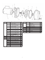
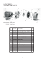
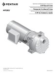
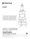
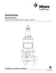
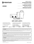
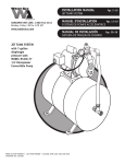
QUICK PRIME INSTALLATION AND SERVICE MANUAL NOTE! To the installer: Please make sure you provide this manual to the owner of the equipment or to the responsible party who maintains the system. Part # 23833A400 | © 2014 Pentair Ltd. | 03/17/14 WARNING! IMPORTANT SAFETY INSTRUCTIONS! READ CAREFULLY BEFORE INSTALLATION 6) The voltage and phase of the power supply must match the voltage and phase of the pump. CALIFORNIA PROPOSITION 65 WARNING: 7) Do not use an extension cord. Above ground joints must be made in an approved junction box. This product and related accessories contain chemicals known to the State of California to cause cancer, birth defects or other reproductive harm. 8) Do not work on this pump or switch while the power is on. 9) Never operate a pump with a frayed or brittle power cord, and always protect it from sharp objects, hot surfaces, oil and chemicals. Avoid kinking the cord. SAFE DRINKING WATER ACT: This product is to be used EXCLUSIVELY for non-potable water services. This product is not anticipated to be used for human consumption so is not designed for the low lead levels stated in the Safe Drinking Water Act. It is illegal to use this product for potable water applications for human consumption, such as drinking water, oral hygiene, hand washing, food preparation and dishwashing. 10) Never service a motor or power cord with wet hands or while standing in or near water or damp ground. 11) The three phase units must be wired by a qualified electrician, using an approved starter box and switching device. FAILURE TO FOLLOW THESE INSTRUCTIONS AND COMPLY WITH ALL CODES MAY CAUSE SERIOUS BODILY INJURY AND/OR PROPERTY DAMAGE. 12) Do not use this pump in or near a swimming pool. 13) Single phase motors are equipped with automatic resetting thermal protectors. The motor may restart unexpectedly, causing the leads to energize or pump to turn on. Three phase motors should be protected by proper thermal and amperage protection. (Check local codes.) 1) Before installing or servicing your pump, BE CERTAIN THE PUMP POWER SOURCE IS TURNED OFF AND DISCONNECTED. 2) All installation and electrical wiring must adhere to state and local codes. Check with appropriate community agencies or contact your local electrical and pump professionals for help. 14) Check for nicks in the wire and pump insulation by using an ohmmeter and checking resistance to ground before installing the pump and after installing the pump. If in doubt on the proper procedure, check with a qualified electrician. 3) CALL AN ELECTRICIAN WHEN IN DOUBT. Pump must be connected to a separate electrical circuit directly from the entrance box. There must be an appropriately sized fuse or circuit breaker in this line. Tying into existing circuits may cause circuit overloading, blown fuses, tripped circuit breakers or a burned-up motor. 15) Do not pump gasoline, chemicals, corrosives or flammable liquids; they could ignite, explode or damage the pump, causing injury and voiding the warranty. 16) Do not run this pump with discharge completely closed. This will create superheated water, which could damage the seal and shorten the life of the motor. This superheated water could also cause severe burns. Always use a pressure relief valve, set below the rating of the tank system. 4) Do not connect pump to a power supply until the pump is grounded. For maximum safety, a ground fault interrupter should be used. CAUTION: FAILURE TO GROUND THIS UNIT PROPERLY MAY RESULT IN SEVERE ELECTRICAL SHOCK. 5) WARNING: Reduced risk of electric shock during operation of this pump requires the provision of acceptable grounding. If the means of connection to the supply-connection box is other than grounded metal conduit, ground the pump back to the service by connecting a copper conductor, at least the size of the circuit conductors supplying the pump, to the grounding screw provided within the wiring compartment. 17) Do not run the pump dry, fail to protect the pump from below freezing temperatures, run the pump with the discharge completely closed or pump chemicals or corrosive liquids. 18) Never work on the pump or system without relieving the internal pressure. 19) Do not pump water above 120° Fahrenheit. his pump is provided with a means for grounding. T To reduce the risk of electric shock from contact with adjacent metal parts, bond supply box to the pump-motor-grounding means and to all metal parts accessible including metal discharge pipes and the like, by means of a clamp, a weld or both if necessary, secured to the equipment-grounding terminal. 20) Never exceed the pressure rating of any system component. GENERAL INSTALLATION The pump should be installed in a clean, dry and well ventilated place allowing room to inspect and service the unit. If located in a pit, the pit should be protected against flooding. 2 The pump must be securely fastened to a solid foundation. The pump should always be mounted in a horizontal position on a level foundation. Failure to properly secure the pump may result in failure of the pump or piping and damage to the surrounding area. Three horsepower and under units are designed to automatically re-prime with or without a check or foot valve in the suction line. Five horsepower units require a check or foot valve for this operation. For initial start-up, fill the pump with liquid through the discharge opening in the top of the case. This can be done before the discharge piping is installed. As an alternative it is recommended to install a tee above the pump and use the top of the tee for priming. Pour in approximately one gallon of water for all units except 5 hp which will need two gallons. Install the discharge piping or pipe plug, if a tee is used. The unit can now be started. SUCTION PIPING Do not exceed 25' total suction lift. If on an installation, excessive total suction lifts are encountered, do one or more of the following to correct this condition: 1.Locate pump nearer to liquid source. 2.Increase pump suction pipe size. 3.Simplify suction piping by elimination of valves and fittings where possible. CHECK OR FOOT VALVE 4.Decrease pump capacity. It is recommended that either a check or foot valve be used in the suction line on permanent installations. This will result in quicker water delivery upon starting, thereby eliminating the priming issues. DISCHARGE PIPING The pump case is tapped for 1-1/2" pipe for 3hp and under units. For 5hp units it is tapped for 2" pipe. Larger or smaller pipe may be used depending upon the installation. The discharge pressure is not to exceed 100 psi for 3hp and under units. For 5hp units the discharge pressure is not to exceed 150psi. If the pump is to be used in conjunction with a pressure tank, a check or foot valve must be used. FLUSHING The unit can be back flushed periodically to remove any sand or debris that may have been pulled into the pump from the liquid source. It is not necessary to remove any piping if a tee is installed above the pump. VOLTAGE DATA Single phase motors as received will be wired for 230V operation. Note: The 2 and 3 hp single phase motors are 230V only. All three phase motors are 230/460V units. Ensure that the motor connections are correct for the voltage available. To back flush the unit, remove the plug in the tee and the pipe plug from the lower front face of the case. Pour water into the top opening until the liquid coming from the lower front opening is clean. Reinstall all pipe plugs or piping and reprime the pump. The voltage available at the motor must be within 10% of the rated voltage. For offset installations be sure that adequate wire size is used for the motor involved. DRAINING THE PUMP To drain the pump, remove the plug from the discharge tee and the pipe plug from the lower front face of the case. If the unit is to be inoperative for an extended period of time, it is suggested that the unit be drained. Suction line should also be drained to prevent freezing. MOTOR PROTECTION Single phase 3/4 to 3 hp motors have built-in thermal protection for all voltages. Three phase and 5 hp single phase motors do not have built-in thermal protection. It is highly recommended that a properly sized magnetic starter be used with all three phase motors. Remove the fuses from the entrance switch to ensure that the unit is not inadvertently started while drained, as damage to the shaft seal would occur. All motors should be equipped with a correctly fused disconnect switch to provide protection. Consult local or national codes for proper fuse protection. SUCTION SCREEN The liquid being pumped should be screened properly to prevent debris from being taken into the system. ROTATION DATA The pump must run in the direction of the arrow on the pump bracket. At the time of installation, momentarily close the entrance switch to determine rotation; if rotation is not correct, interchange any two of the three motor leads, which will reverse the rotation. PUMP DISASSEMBLY INSTRUCTIONS It is not necessary to remove the suction and discharge piping as the pump case is designed so that no wear would occur which would necessitate replacing this part. INITIAL PRIMING Do Not Run Pump Dry 1.Drain the pump of its liquid charge and open the power supply switch contacts and remove fuses. The pump must be filled with water for the initial start. Failure to do so will result in damage to the mechanical shaft seal. 2.Disconnect the electrical wiring from the motor and remove the cap screws that secure the pump bracket to the pump case. 3 3.The motor and bracket assembly can now be removed from the pump case by pulling horizontally away from the case. 3. Suction lift too great; check with vacuum gauge. Check or foot valve, if used, may be completely plugged or suction piping may be completely plugged. 4.Remove the O-ring from the case inner neck and then remove the cap screws that hold the diffuser in place and lift off diffuser. 4. Air leak in suction piping. 5. Wrong motor rotation. 5.All three phase and 5 hp units – hold impeller or motor shaft and remove hex nut located in the impeller eye and unscrew the impeller. 6. Shaft seal leaking under priming conditions. 7. Motor not up to speed; check for incorrect voltage. 8. Plugged impeller. 6.The mechanical shaft seal components can now be removed from the motor shaft and bracket respectively. Not enough water or pressure 7.Remove the cap screws that secure the bracket to the motor and remove the bracket. The deflector can now be removed from the motor shaft. 1. Air leak in suction piping. 8.Remove the O-ring from the bracket neck. 3. Discharge system head too great. A new shaft seal should always be used when rebuilding a pump. All pump parts should be cleaned thoroughly before being reassembled. 4. Impeller, suction pipe, check or foot valve partially plugged. PUMP ASSEMBLY INSTRUCTIONS 6. Suction lift too great. 1.Slip deflector onto the motor shaft extension and with motor in vertical position, place bracket onto motor face register and secure bracket to motor with cap screws. Ensure that the motor, when in operating position, has the shell air slots in the down position. 7. Insufficient submergence of suction pipe. Suction pipe inlet should be at least 3 feet below the liquid surface at all times. 2. Motor not up to speed; check for incorrect voltage or low voltage. 5. Wrong motor rotation. 8. Pump too small for installation involved. 9. Suction piping too small causing excessive total suction lift. 2.Place stationary shaft seal component over pump shaft extension and seat into provided bracket bore. Follow with the rotating seal component onto the motor shaft. 10. Air or gas entrained in liquid. 11. Worn impeller or diffuser. Pump loses prime after starting 3.Place the impeller onto the pump shaft extension until the impeller back hub rests on the shaft shoulder. Screw in impeller capscrew. 1. Air leak in suction piping. 2. Total suction lift too great. 4.Place the diffuser over the impeller with the diffuser volute face against the bracket. Equally space three .005 shims between the impeller hub and the diffuser I.D. Assemble the cap screws and tighten alternately, so the diffuser is not pulled to one side. Remove the three shims and as the impeller is revolved it should turn freely. 3. Insufficient submergence of suction pipe; check pumping water level. Motor overheats 1. Check rotating element to ensure that it turns freely. 2. Low voltage at the motor. Check electrical connections to ensure tight contact. 5.Place gasket over the bracket register diameter and position against the provided face, then place gasket over the inner neck in the pump case and place against the provided face. The assembly can now be reassembled to the pump case. 3. Poor ventilation. Pump vibrates or is noisy 1.Insufficient pump foundation. 6.Using cap screws, secure bracket to case. The motor wiring can now be connected and the unit reprimed. Install the previously removed fuses from the entrance switch and close the switch; the unit is now in operation again. 2.Excessive total suction lift. 3.Bent shaft or worn motor bearings. 4.Impeller partially clogged. TROUBLESHOOTING No water delivered 1. Pump not properly primed. 2. Discharge system head too great; in this case, a pressure gauge at the pump discharge will show shut off pressure. 4 12 4 8 9 11 14 13 2 5 6 1 7 3 10 QP Series Centrifugal Pump Parts List Reference 1 Part No. 20934A000 20593A000 20935A000 20594A000 20589A000 20595A000 20591A000 20596A000 20592A000 20597A000 2 3 4 5 6 05059A318 20598D000 19101A008 – 20599B000 20600B000 20600B003 20600B004 20601B000 20601B003 20601B004 20602B000 20603B000 Description Motor, 3/4 hp, 115/230V, 1 ph QP-7 – Replaces 20587A Motor, 3/4 hp, 200/230/460V, 3 ph QP7-3 – Replaces 21037A on QP7-03 Motor, 1 hp, 115/230V, 1 ph QP-10 – Replaces 20588A Motor, 1 hp, 200/230/460V, 3 ph QP10-3 – Replaces 21038A on QP10-03 Motor, 1-1/2 hp, 115/230V, 1 ph – QP15 Motor, 1-1/2 hp, 200/230/460V, 3 ph QP15-3 – Replaces 21039A on QP15-03 Motor, 2 hp, 230V, 1 ph – QP20 Motor, 2 hp, 200/230/460V, 3 ph QP20-3 – Replaces 21040A on QP20-03 Motor, 3 hp, 230V, 1 ph – QP30 Motor, 3 hp, 200/230/460V, 3 ph QP30-3 – Replaces 21041A on QP30-03 Deflector, Rubber Bracket Screw, Cap 3/8-16" x 7/8" Seal Impeller – QP7, QP7-3, QP7-03 Impeller, Brass – QP10, QP10-3, QP10-03 Impeller, GFN-3 – QP10 Impeller, GFN-3 – QP10-3, QP10-03 Impeller, Brass – QP15, QP15-3, QP15-03 Impeller, Lexan® – QP15 Impeller, GFN-3 – QP15-3, QP15-03 Impeller – QP20, QP20-3, QP20-03 Impeller – QP30, QP30-3, QP30-03 Qty. Reference 7 1 Part No. 20559D000 20560D000 1 1 8 9 10 11 12 13 14 1 1 1 1 1 1 1 1 1 4 1 1 1 1 1 1 1 1 1 1 5 20561D000 19099A014 05014A167 05014A166 20604D000 19102A002 05022A009 19109A070 Description Diffuser – QP7, QP7-3, QP7-03, QP10, QP10-3, QP10-03 Diffuser – QP15, QP15-3, QP15-03, QP20, QP20-3, QP20-03 Diffuser – QP30, QP30-3, QP30-03 Screw, Cap 1/4-20 x 1-1/2 Gasket, 8-3/4" OD Gasket, 2-1/8" OD Case Screw, Cap 7/16-14 x 1-1/4" Plug, 1/4 NPT Nut, 7/16-20 SST – Used on 3 Phase Units Only Qty. 1 1 1 3 1 1 1 4 1 1 5 HP QP SERIES Centrifugal Pump Parts List 8 1 15 11 12 9 2 14 10 6 5 3 13 7 16 4 17 18 Model QP50B - Single Phase QP50B3 - Three Phase Ref. No. 1 2 3 4 5 6 7 8 9 10 11 12 13 14 15 16 17 18 Part No. Description 26579A000 26579A001 26579B000 19101A007 05030A004 19109A017 19101A019 19103A045 26545E000 21181A016 26546C000 05876A225 26583A000 19099A022 05876A138 26544D000 26547D000 05876A059 05022A009 Motor, 5 hp, 230V, 1Phase – QP50B Motor, 5 hp, 230V, 3 Phase – QP50B3 Bracket, Motor Support Cap Screw 3/8-16 x 3/4 3/8 Flat Washer 3/8 Hex Nut Cap Screw 3/8-16 x 1-1/4 Cap Screw 1/2-13 x 1-3/4 Bracket, Pump Seal Impeller, Brass O-ring Impeller Screw 1/2-20 x 1-3/4 Cap Screw O-ring Case Diffuser O-ring Plug, 1/4" NPT 6 Qty. 1 1 4 4 4 4 4 1 1 1 1 1 3 1 1 1 1 1 7 STANDARD LIMITED WARRANTY CENTRIFUGAL & RECIPROCATING PUMPS Pentair Myers® warrants its products against defects in material and workmanship for a period of 12 months from the date of shipment from Pentair Myers or 18 months from the manufacturing date, whichever occurs first – provided that such products are used in compliance with the requirements of the Pentair Myers catalog and technical manuals. During the warranty period and subject to the conditions set forth, Pentair Myers, at its discretion, will repair or replace to the original user, the parts that prove defective in materials and workmanship. Pentair Myers reserves the right to change or improve its products or any portions thereof without being obligated to provide such a change or improvement for prior sold and/or shipped units. Seals, piston cups, packing, plungers, liners and valves used for handling clear, fresh, nonaerated water at a temperature not exceeding 120ºF are warranted for ninety days from date of shipment. All other applications are subject to a thirty day warranty. Accessories such as motors, engines and auxiliary equipment are warranted by the respective manufacturer and are excluded in this standard warranty. Under no circumstance will Pentair Myers be responsible for the cost of field labor, travel expenses, rented equipment, removal/reinstallation costs or freight expenses to and from the factory or an authorized Pentair Myers service facility. This limited warranty will not apply: (a) to defects or malfunctions resulting from failure to properly install, operate or maintain the unit in accordance with the printed instructions provided; (b) to failures resulting from abuse, accident or negligence; (c) to normal maintenance services and parts used in connection with such service; (d) to units that are not installed in accordance with applicable local codes, ordinances and good trade practices; (e) if the unit is moved from its original installation location; (f) if unit is used for purposes other than for what it is designed and manufactured; (g) to any unit that has been repaired or altered by anyone other than Pentair Myers or an authorized Pentair Myers service provider; (h) to any unit that has been repaired using non factory specified/OEM parts. Warranty Exclusions: PENTAIR MYERS MAKES NO EXPRESS OR IMPLIED WARRANTIES THAT EXTEND BEYOND THE DESCRIPTION ON THE FACE HEREOF. PENTAIR MYERS SPECIFICALLY DISCLAIMS THE IMPLIED WARRANTIES OF MERCHANTABILITY AND FITNESS FOR ANY PARTICULAR PURPOSE. Liability Limitation: IN NO EVENT SHALL PENTAIR MYERS BE LIABLE OR RESPONSIBLE FOR CONSEQUENTIAL, INCIDENTAL OR SPECIAL DAMAGES RESULTING FROM OR RELATED IN ANY MANNER TO ANY PENTAIR MYERS PRODUCT OR PARTS THEREOF. PERSONAL INJURY AND/OR PROPERTY DAMAGE MAY RESULT FROM IMPROPER INSTALLATION. PENTAIR MYERS DISCLAIMS ALL LIABILITY, INCLUDING LIABILITY UNDER THIS WARRANTY, FOR IMPROPER INSTALLATION. PENTAIR MYERS RECOMMENDS INSTALLATION BY PROFESSIONALS. Some states do not permit some or all of the above warranty limitations or the exclusion or limitation of incidental or consequential damages and therefore such limitations may not apply to you. No warranties or representations at any time made by any representatives of Pentair Myers shall vary or expand the provision hereof. 1101 MYERS PARKWAY ASHLAND, OHIO, USA 44805 419-289-1144 WWW.FEMYERS.COM Warranty Rev. 12/13