1
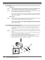
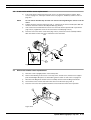
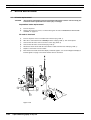
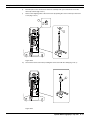
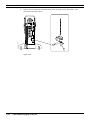
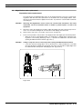
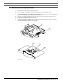
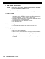
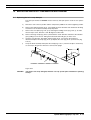
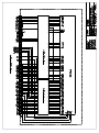
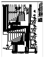
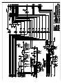
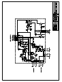
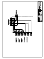
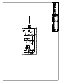
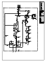
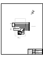
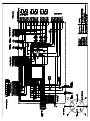
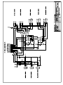
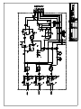
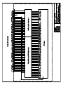
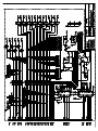
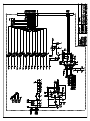
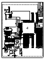
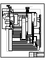
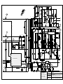
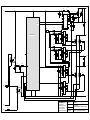
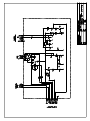
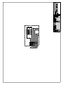
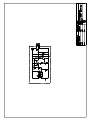
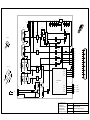
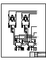
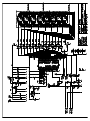
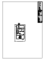
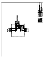
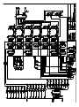
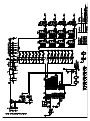
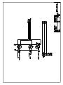
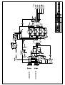
Chapter H - PARTS REPLACEMENT & REPAIR
8.2
REPLACING SENSORS & SWITCHES
Limit sensors
Hall-sensors
NOTE
When ordering the Hall-sensors specify the type of the sensor (e.g. UP/DOWN mechanism: Lift up sensor). There Hall-sensor cable assemblies of different length.
NOTE
The new Hall-sensor assembly must be installed in exactly same way as the old one.
Incorrect cable routing may cause injury or harm to the unit.
Always check the operation of the Hall-sensors after replacement in the Internal signal display
mode. See instructions given in section “ADJUSTING SENSORS & SWITCHES” on page F-44.
Adjust the sensors if needed.
Microswitches
NOTE
The new Microswitch cable assembly must be installed in exactly same way as the old
one. Incorrect cable routing may cause injury or harm to the unit.
Always check the operation of the Microswitches after replacement in the Internal signal display
mode. See instructions given in section “ADJUSTING SENSORS & SWITCHES” on page F-44.
Adjust the switches if needed.
8.3
Lift motor rotation sensor replacement
a)
Turn off the power. Remove the necessary covers, see instructions given in sections “Base
covers” on page H-2, “Telescopic column covers” on page H-2 and “Stationary column covers”
on page H-3.
b)
Remove the Lift motor, see instructions given in section “Lift motor replacement” on page H-26.
NOTE
Do not remove the Allen key from the new sensor before tightening the sensor to the lift
motor.
c)
Pull the old sensor from the motor (Fig. H.27, 1). The base of the sensor and the pulse disk will
remain on the motor. Remove the old pulse disk (Fig. H.27, 2).
d)
If the sensor base moved when the sensor was removed, check its position with a special tool
(Fig. H.27, 3). Tighten the screws of the sensor base if needed (Fig. H.27, 4).
e)
Install the new sensor to the sensor base (Fig. H.27, 5). Fasten the sensor assembly with the
Allen key which is in the new sensor. Check the sensor operation.
5
4
2
3
1
Figure H.27
H-24
Sophie Mammography X-ray unit
Technical Manual
Chapter H - PARTS REPLACEMENT & REPAIR
8.4
REPLACING SENSORS & SWITCHES
C-arm motor rotation sensor replacement
a)
NOTE
Turn off the power. Remove the necessary covers, see instructions given in sections “Base
covers” on page H-2, “Telescopic column covers” on page H-2, “Stationary column covers” on
page H-3.
Do not remove the Allen key from the new sensor before tightening the sensor to the lift
motor.
b)
Pull the old sensor from the motor (Fig. H.28, 1). The base of the sensor and the pulse disk will
remain on the motor. Remove the old pulse disk (Fig. H.28, 2).
c)
If the sensor base moved when the sensor was removed, check its position with a special tool
(Fig. H.28, 3). Tighten the screws of the sensor base if needed (Fig. H.28, 4).
d)
Place the new sensor to the sensor base (Fig. H.28, 5). Fasten the sensor assembly with the
Allen key which is in the new sensor. Check the sensor operation.
5
4
2
1
3
Figure H.28
8.5
MAG-motor rotation sensor replacement
a)
Drive the C-arm to upright position. Turn off the power.
b)
Remove the following C-arm covers: C-arm top, lower, vertical covers, Vertical cover support
plate and the Right side panel, see instructions given in section “C-arm covers” on page H-4.
c)
Disconnect the Mag-motor rotation sensor assembly connector from the Mag control PCB.
d)
Unscrew the sensor screws and remove the sensor from the motor (Fig. H.29, 1)
e)
Place the new sensor to its position and in the service mode check the sensor operation.
1
Figure H.29
Technical Manual
Sophie Mammography X-ray unit
H-25
Chapter H - PARTS REPLACEMENT & REPAIR
9
MOTOR REPLACEMENT
9.1
Lift motor replacement
CAUTION
MOTOR REPLACEMENT
The Lift motor replacement must be performed with extreme caution. The incorrectly performed Lift motor replacement can cause injury or damage.
Preparations before replacement
a)
Turn off the power.
b)
Remove the necessary covers, see instructions given in section “REMOVING & REPLACING
COVERS” on page H-1.
Lift motor is functional
a)
Turn on the power. Place a wooden rod on the base (Fig. H.30, 1).
b)
Drive the C-arm rotation motor carefully to hit the rod (Fig. H.30, 2). Turn off the power.
c)
Unscrew the Lift motor worm screw nut’s screws (Fig. H.30, 3).
d)
Unscrew the Lift motor screw and nut (Fig. H.30, 4).
e)
Disconnect the Lift motor and the Pulse detector cables from the Base PCB (Fig. H.30, 5).
f)
Replace a new motor in reverse order.
g)
Enter the Service mode and select display of internal signal 5, see section “Diagnostic display of
internal signals” on page C-10. Check that the motor is functional.
3
3
4
2
Lift motor 1 091097
1
2
4
5
Figure H.30
H-26
Sophie Mammography X-ray unit
Technical Manual
Chapter H - PARTS REPLACEMENT & REPAIR
MOTOR REPLACEMENT
Lift motor not functional
a)
Place a board in right length between the C-arm rotation motor and the base (Fig. H.31, 1).
b)
Unscrew the Lift motor worm screw nut’s screws (Fig. H.31, 2).
c)
Unscrew the Lift motor screw and nut (Fig. H.31, 3).
d)
Disconnect the Lift motor and the Pulse detector cables from the Base PCB (Fig. H.31, 4).
e)
Replace a new motor in reverse order.
f)
Turn on the power.
g)
Enter the Service mode and select display of internal signal 5, see section “Diagnostic display of
internal signals” on page C-10. Check that the motor is functional.
2
1
Lift motor 2 091097
1
3
3
4
Figure H.31
Technical Manual
Sophie Mammography X-ray unit
H-27
Chapter H - PARTS REPLACEMENT & REPAIR
9.2
MOTOR REPLACEMENT
C-arm rotation motor replacement
CAUTION
Removing the motor causes the C-ARM to rotate freely. It must be supported before loosening the drive chain to prevent injuries or harm to the equipment
CAUTION
Protect yourself against electrical shock. The unit contains live parts on some PC-boards
and connectors.
Preparations before replacement
a)
Drive the telescopic column to the highest position. Turn off the power.
b)
Remove the necessary covers: base covers, stationary column covers, telescopic column covers
and hood (see “REMOVING & REPLACING COVERS” on page H-1).
C-arm rotation motor is functional
H-28
NOTE
See figures on section “C-arm rotation motor is not functional” on page H-29.
CAUTION
The C-arm must be in upright position when removing the gas-spring to prevent injuries
or harm to the equipment.
a)
Remove the gas spring, follow the instructions given in section “GAS SPRING REPLACEMENT”
on page H-38.
b)
Turn on the power and in the service mode drive the unit to the -135° position. Turn off the power
and wait for 2 minutes.
c)
Support (you may need a helping hand) the C-arm at the tubehead while removing the four
screws that fixes the chain to the worm-screw nut (see Fig. H.33).
d)
Mark the place of the rotation lower detector assembly with a pen and remove it from the
telescopic column (see Fig. H.34).
e)
Remove the stopping collar of the worm-screw by opening the screw on the top of the worm
screw (see Fig. H.34).
f)
Unscrew the worm-screw nut by rotating the worm-screw with the clamp, or by driving the motor
(see Fig. H.35).
g)
Disconnect the cables from the motor.
h)
Remove the screw that fixes the rotation motor to the telescopic column and remove the motor
(see Fig. H.36).
Sophie Mammography X-ray unit
Technical Manual
Chapter H - PARTS REPLACEMENT & REPAIR
MOTOR REPLACEMENT
C-arm rotation motor is not functional
a)
Open the four bolts of the motor cover (Fig. H.32, 1) and remove the cover (Fig. H.32, 2).
b)
Remove the stator (Fig. H.32, 3).
c)
Remove the rotation sensor assembly (Fig. H.32, 4).
d)
Open the pulse detector screw with the special Allen key (delivered with the rotation motor
assembly) (Fig. H.32, 5).
e)
Remove the rotor (Fig. H.32, 6).
f)
Rotate the rotation motor worm-screw with 8 mm Allen key (Fig. H.32, 7) to move the C-arm to
upright position. The gas spring (Fig. H.32, 8) can be removed in this position.
8
7
1
2
Rot.motor 1 091097
6
3
5
4
Figure H.32
Technical Manual
CAUTION
The C-arm must be in upright position when removing the gas-spring to prevent injuries
or harm to the equipment.
g)
Remove the gas spring, follow the instructions given in section “GAS SPRING REPLACEMENT”
on page H-38.
Sophie Mammography X-ray unit
H-29
Chapter H - PARTS REPLACEMENT & REPAIR
MOTOR REPLACEMENT
h)
Rotate the worm-screw to move the C-arm to -135° position (Fig. H.33, 1).
i)
Support (you may need a helping hand) the C-arm at the tubehead while removing the four
screws that fixes the chain to the worm-screw nut (Fig. H.33, 2). Let the arm rotate slowly down
so that the tubehead is towards the floor.
1
Rot.motor 2 091097
2
Figure H.33
j)
H-30
Disconnect the motor power cable, pulse cable and the grounding wire from the motor.
Sophie Mammography X-ray unit
Technical Manual
Chapter H - PARTS REPLACEMENT & REPAIR
MOTOR REPLACEMENT
k)
Mark the place of the rotation lower detector assembly with a pen and remove it from the
telescopic column (Fig. H.34, 1).
l)
Remove the stopping collar of the worm-screw by opening the screw on the top of the worm
screw (Fig. H.34, 2).
1
Rot.motor 3 091097
2
Figure H.34
m)
Unscrew the worm-screw nut by rotating the worm-screw with the clamp (Fig. H.35, 1).
Rot.motor 4 091097
1
Figure H.35
Technical Manual
Sophie Mammography X-ray unit
H-31
Chapter H - PARTS REPLACEMENT & REPAIR
Remove the screw that fixes the rotation motor to the telescopic column (Fig. H.36, 1) and
remove the motor (Fig. H.36, 2).
Rot.motor5 091097
n)
MOTOR REPLACEMENT
1
2
Figure H.36
H-32
Sophie Mammography X-ray unit
Technical Manual
Chapter H - PARTS REPLACEMENT & REPAIR
MOTOR REPLACEMENT
Placing a new motor
a)
Remove the stopping collar of the worm-screw (Fig. H.37, 1).
b)
Unscrew the worm-screw nut from the worm-screw (Fig. H.37, 2).
c)
Remove the guide plate and the screws from the worm-screw nut (Fig. H.37, 3).
d)
Slide the guide plate in the gliding groove to the level of the chain guide opening.
e)
Put in the new motor and fasten it to the telescopic column (Fig. H.37, 4).
1
2
3
4
Figure H.37
Technical Manual
f)
Screw the worm-screw nut to the correct height and fasten the four screws that holds the nut
fixed to the plate in the groove.
g)
Lift up the tubehead until the chain ends reaches the nut. Fix the chain ends to the nut with the
screws.
h)
Replace the stopping collar of the worm-screw.
i)
Fasten the rotation lower detector assembly to the marked place.
j)
Connect all the motor cables. Check that all the cable connectors are connected to right places.
k)
Replace the hood tentatively.
l)
Connect the power and check the rotation limit sensor adjustment, follow the instructions given in
chapter F, section 5.5.
m)
Drive the C-arm to the upright position and replace the gas-spring, see instructions in “GAS
SPRING REPLACEMENT” on page H-38.
n)
Replace the covers and the hood and check that the unit is fully functional.
Sophie Mammography X-ray unit
H-33
Chapter H - PARTS REPLACEMENT & REPAIR
9.3
MOTOR REPLACEMENT
Compression motor replacement
a)
Drive the C-arm to the upright position. Drive the cassette table to the upper position (MAG 1.8).
b)
Turn off the power.
c)
Remove the following C-arm covers: top, lower and vertical covers and vertical cover support
plate. See instructions given in section “C-arm covers” on page H-4.
d)
Disconnect the Compression motor cable from the Front collector PCB (Fig. H.38, 1).
e)
Open the necessary cable bindings (Fig. H.38, 2) and route the cable carefully from the C-arm
center frame openings. Make sure that the wires do not loosen from the connector pins.
Stand-off bracket
9
6
3
4
7
Front collector PCB
8
Motor bracket
5
1
Motor
2
Figure H.38
H-34
f)
Thread the drive belt (Fig. H.38, 3) from the Drive wheel (Fig. H.38, 4) and from the Worm-screw
belt wheel.
g)
Unscrew the four nuts that hold the Stand-off bracket in the Motor bracket (Fig. H.38, 5).
h)
Remove the Motor bracket and the Motor from the Stand-off bracket. Make sure that the spacers
(Fig. H.38,6) do not fall to the cassette shelf casting. Remove the spacers.
i)
Unscrew the Motor belt drive wheel’s screw (Fig. H.38, 7) with an Allen key and remove the drive
wheel (Fig. H.38, 4).
j)
Unscrew the Compression motor holding nuts (Fig. H.38, 8) and remove the Motor.
k)
Install the new motor and replace the removed parts in reverse order.
l)
Check the strain of the drive belt. It should be slightly elastic.
m)
When needed, loosen the Motor stand-off bracket’s screws (Fig. H.38, 9), adjust the bracket
position and tighten the screws.
n)
Enter the Service mode and select display of internal signal 7, see section “Diagnostic display of
internal signals” on page C-10. Check that the motor is functional.
Sophie Mammography X-ray unit
Technical Manual
Chapter H - PARTS REPLACEMENT & REPAIR
9.4
MOTOR REPLACEMENT
Magnification motor replacement
Preparations before replacement
The replacement of the Magnification motor can be performed easier if you have a special locking device. With this device the replacement can be made in this same upright position, otherwise the C-arm must be tilted to slightly more that 90 ° to prevent the cassette table mechanism
from falling out.
CAUTION
Removing the Magnification motor loosens the cassette table mechanism. The whole
mechanism can fall out. Extreme caution is needed to prevent injuries or harm to the
equipment.
a)
Drive the C-arm to the upright (CC-) position. Adjust the height of the unit so that the top of the Carm is at a convenient working level. Turn the unit off and unplug it from the mains.
b)
Remove the C-arm covers, see section “C-arm covers” on page H-4.
c)
There are two possible C-arm positions: the upright position and slightly past horizontal position.
•
CAUTION
When the C-arm is at the upright position, you need always a locking device. Attach the locking device to the bearing shaft (Fig. H.39, 1). It prevents the tubehead to fall down when
opening the MAG-mechanism thread. (Fig. H.39, a)
Failing to obey this rule can cause injury when opening the MAG-mechanism thread.
•
If you don’t have the locking device, turn on the power for a while and drive the C-arm little
more that 90 degrees (slightly past horizontal) so that the cassette table is slightly higher that
the tubehead. Turn off the power and unplug the unit. (Fig. H.39, b)
1
(a)
(b)
Figure H.39
Technical Manual
Sophie Mammography X-ray unit
H-35
Chapter H - PARTS REPLACEMENT & REPAIR
MOTOR REPLACEMENT
Magnification motor replacement
a)
Unscrew the three screws that hold the Magnification motor in the Tubehead (Fig. H.40, 1).
b)
Disconnect the Tubehead temperature sensor cable and the Mag pulse hall cable from the Mag
control PCB.
c)
Remove the motor from the Tubehead.
d)
Remove the Clutch (Fig. H.40, 2) from the motor axle.
e)
Remove the Mag control PCB (Fig. H.40, 3) and the Rotation sensor assembly (Fig. H.40, 4)
from the motor.
f)
Place the Clutch to the new motor. Install the motor to the Tubehead and replace the removed
parts to the motor. Connect the cables to the Mag control PCB.
g)
Detach the locking device. Turn on the power and check the function of the motor.
h)
Calibrate the MAG/LOAD mechanism position by driving the mechanism once from side to side
(from limit sensor to limit sensor).
i)
Turn off the power and replace the removed covers.
1
3
4
2
NOTE
LBL-7870031
BEFORE WORKING ON THE MAGNIFICATION DRIVE ASSEMBLE, DRIVE THE C-ARM TO
THE HORIZ
ONTAL POSITION, OR IF THIS IS NOT POSSIBLE, LOCK THE TUBEHEAD &
CASSETTE TABLE ASSEMBLE IN POSITION TO PREVENT THE C-ARM FROM DROPPING
IF THE BALL SCREW IS RELEASED.
Figure H.40
H-36
Sophie Mammography X-ray unit
Technical Manual
Chapter H - PARTS REPLACEMENT & REPAIR
REPLACING THE LABELING HEAD
10 REPLACING THE LABELING HEAD
a)
Unscrew the six table cover screws (Fig. H.41, 1)
b)
Lift up the table cover slightly and pull it away from the table casting (Fig. H.41, 2).
c)
Unscrew the M4x8 DIN 914 labeling head fastening screw (Fig. H.41, 3). Turn the labeling head
carefully upwards (Fig. H.41, 4) and lift it from its position.
d)
Disconnect the labeling head cable from the Shelf collector PCB connector P8 (Fig. H.41, 5).
e)
Install the new labeling head in reverse order.
f)
Perform the labeling head adjustment according to the instructions given in section “Cassette
table size identification switches” on page F-61.
1
Label1.eps
2
5
4
3
Figure H.41
Technical Manual
Sophie Mammography X-ray unit
H-37
Chapter H - PARTS REPLACEMENT & REPAIR
GAS SPRING REPLACEMENT
11 GAS SPRING REPLACEMENT
CAUTION
The gas spring is always in tension. Before removing it you must always adjust the tension to zero to prevent injuries and damage to the unit
Preparations before replacement
Remove the TELESCOPIC COLUMN REAR PANEL to access the gas spring. Drive the unit up.
11.1 C-arm is functional
•
Drive the C-ARM to straight upright (CC-position) and turn off the power.
•
Loosen a few revolutions the upper an lower locking nuts on the tension adjustment mechanism (at the top of the gas spring). Please note that the upper locking nut and its thread in a
mirror image from the normal, so it must be turned in the opposite direction.
•
Release the gas-spring tension by rotating the tension adjustment bolt (the middle nut), until
the gas-spring feels loose (the gas spring grows longer).
•
Remove the locking washers at both ends of the gas spring shafts.
•
Gently pull out the gas spring.
11.2 C-arm is not rotating
•
You need a clamping device for the gas spring, otherwise you proceed as above.
11.3 Replacing the gas-spring
C-ARM IS FUNCTIONAL
H-38
•
Make sure the C-ARM is in upright position.
•
Adjust the length of the gas spring (by turning the tension adjustment bolt) until it fits the two
shafts. Note that the piston should be downwards and the gas spring upwards.
•
Replace the two locking washers that secures that the gas spring stays in place. Make sure
these are not harmed.
•
Tighten the gas spring by adjusting it into tension by rotating the tension adjustment bolt until
the gas spring is compressed a cm or so. Secure the adjustment by the two locking nuts on
the same bolt.
Sophie Mammography X-ray unit
Technical Manual
Chapter H - PARTS REPLACEMENT & REPAIR
REPLACING PARTS IN COMPRESSION MECHANISM
12 REPLACING PARTS IN COMPRESSION MECHANISM
12.1 Replacing the twin-comp damper
The spare part number is 7616108. Please return any old spare parts in stock for free replacement.
a)
Drive the C-arm to the CC-position and the compression paddle to the release (highest) position.
b)
Remove the small Circlip (Fig. H.42, 1) that holds the shock absorber axle attached to the tilting
mechanism. Let the drum assembly slowly drop down.
c)
Remove the cover plate (Fig. H.42, 2) by removing the holding screws (Fig. H.42, 3). To make
the next steps easier, drive the C-arm 90 degrees to either side.
d)
Remove the large Circlip (Fig. H.42, 4) that holds the shock absorber and remove the absorber
(5) by pulling it out to the rear. Tilting the mechanism down will give you more room.
e)
Insert the new absorber. The rubber crimp ring (Fig. H.42, 7) must be in the position as
illustrated. Replace the Circlip (Fig. H.42, 4). Replace the cover (Fig. H.42, 2) and screws (Fig.
H.42, 3).
f)
Lift up the drum assembly and replace the Circlip (Fig. H.42, 1). Turn the Circlips to ensure they
are correctly in the grooves. Drive the C-arm back to upright.
3
2
7
1
5
6
4
Figure H.42
CAUTION
Technical Manual
The Circlips are easily damaged, therefore use only special pliers intended for replacing
Circlips.
Sophie Mammography X-ray unit
H-39
Chapter H - PARTS REPLACEMENT & REPAIR
H-40
Sophie Mammography X-ray unit
REPLACING PARTS IN COMPRESSION MECHANISM
Technical Manual
Chapter
I
Technical Manual
SCHEMATICS & DIAGRAMS
Sophie Mammography X-ray unit I-1
Chapter I - SCHEMATICS & DIAGRAMS
I-2
Sophie Mammography X-ray unit
Technical Manual
VCC
GND
OUT
P1
LABELING
MOTOR
M
CASSETTE
POSITION
DETECTOR
1
MA2
2
MLA1
3
MB2
4
MLB1
5
CPL
6
GND
7
LRL
8
+VAA
TO SHELF COLLECTOR PCB P8
VCC
IC1
OUT
GND
LABELING
REFERENCE SENSOR
PLANMED OY
Asentajankatu 6,
00810 Helsinki Finland
tel: 358-0-75905300
telex: 122430 plan sf
telefax: 358-0-75905555
17.02.1992
SOPHIE
Labeling circuit board
Schematic Diagram
P. Strömmer
109-03-09-D (7810009)
6
LB+
LB-
TO CAPACITOR PCB P1
P5
VSH
D38
+VP
PFC PART
Page 3
-VP
C23
VS
+PF
F1
R+
R89
+VP
+VP
Q1
R18
PE
-VDC
c32
MAC
a32
MAC
MAM
c28
MAM
a28
MAM
c26
MAS
a26
MAS
+PF
+SP
R-
-VP
TUBE POWER PART
Page 5
+SP
+VFB
DIRA
PHCA
PLSA
+VCC
GND
LOW VOLTAGE PART
Page 4
C21
-VP
CONNECTORS LAMP
+LMP
Page 2
-VBB
+VAA
+VCC
GND
LFE
LFE
SFE
VFC
HST
a30
c24
a24
c22
c20
HV2
a20
HV2
c18
-VBB
+VAA
+VCC
GND
BVC
SFE
VFC
HST
HV2
LAMP
+LMP
BVC
MAS
c30
a22
TRG
ICH
VAC
PE
P3
INTERFACE
PCB
Page 6
MAC
LP-
N
-DC
-VP
LB+ LB-
C22
+VP
LP+
EXP
HEN
KVC
a18
HV2
c16
HV1
a16
HV1
+VFB
c14
HV1
a14
HV1
TO TUBE CONNECTOR PCB P1
LB-
5
3
C+
L
4
2
1
N
+VP
L
-VP
N
L
LP-
P6
LB+
5
LP-
4
LP+
3
C-
2
LP+
1
C-
C+
TO SYNC PCB P2
c12
BIAS
FILF
FIC
FISF
a12
c10
a10
EXP
HEN
KVC
DIRA
PHCA
PLSA
FIC
FISF
FILF
MAFMAF+
KVF-
c8
FILF
a8
BIAS
c6
FIC
a6
FISF
c4
MAF-
a4
MAF+
c2
KVF-
a2
KVF+
KVF+
PLANMED OY
Asentajankatu 6
00810 Helsinki Finland
tel: 358-9-75905300
telex: 122430 plan sf
telefax: 358-9-75905555
24.06.1999
H.Lehtinen
P.Strömmer
SOPHIE
Power supply
Schematic Diagram (main block)
109 - 03 - 16 - 1/6 - M2 (20000049)
a2 c3
a4 c5
a5 c6
a6 c7
a7 c8
GND
LAMP
+LMP
GND
FAN
+VCC
FAN
GND
GND
EXP
PEN
STOP
SYNC
GND
TO REAR COLLECTOR
PCB P3
SCL
STOP
STOP
SCL
UP
STOP
DWN
PRE
MUL
REL
MDL
+VCC
TO SHELF COLLECTOR
PCB P3
GND
STOP
DIRM
STOP
MGEN
T+
GND
+VCC
X-
X+
SOC
SS3
SS2
GND
SS1
L/B
CDSL
CDBL
PLSM
TO MAG CONTROL
PCB P1
TO EXPOSURE CTL
PCB P1
BPL
CPL
BRL
LRL
+VAA
a8 c9
+VCC
MB2
MSB1
MA2
+VCC
MSA1
+VAA
GND
M/FC
MRL
a3 c4
TO SHELF COLLECTOR
PCB P5
F/C
FRL
a1 c2
CRL
MTA1
c1
MA2
MTB1
P2
MB2
TO COLLIMATOR
PCB P1
a9 c10 a10 c11 a11 c12 a12 c13 a13 c14 a14 c15 a15 c16 a16 c17 a17 c18 a18 c19 a19 c20 a20 c21 a21 c22 a22 c23 a23 c24 a24 c25 a25 c26 a26 c27 a27 c28 a28 c29 a29 c30 a30 c31 a31 c32 a32
GND
+VCC
+VAA
-VBB
+LMP
VR6
K2
R62
HST
P4
FAN
DIRA
PHCA
PLSA
KVC
HEN
EXP
LAMP
BVC
SFE
KVF-
KVF+
MAF-
MAF+
FISF
FILF
FIC
VFC
LFE
SFE
BVC
LAMP
PEN
EXP
FAN
SYNC
SCL
HEN
KVC
UP
DWN
REL
PRE
MDL
T+
MUL
STOP
PLSM
DIRM
PLSA
MGEN
C/S
PHCA
X+
DIRA
SOC
SS3
X-
SS2
L/B
SS1
CDBL
CDSL
CPL
BPL
BRL
+VAA
LRL
a8 c8 a9 c9 a10 c10 a11 c11 a12 c12 a13 c13 a14 c14 a15 c15 a16 c16 a17 c17 a18 c18 a19 c19 a20 c20 a21 c21 a22 c22 a23 c23 a24 c24 a25 c25 a26 c26 a27 c27 a28 c28 a29 c29 a30 c30 a31 c31 a32 c32
-VBB
+VCC
GND
a7 c7
+VAA
a6 c6
GND
a5 c5
HST
F/C
MRL
CRL
a3 c3 a4 c4
FRL
MA2
a2 c2
MA1
a1 c1
MB2
P1
M/FC
LFE
VFC
FILF
FIC
FISF
MAF+
MAFKVF+
KVF-
MB1
D27
TO TUBE CPU STAND PCB P1
PLANMED OY
24.06.1999
Asentajankatu 6,
00810 Helsinki Finland
tel: 358-9-75905300
telex: 122430 plan sf
telefax: 358-9-75905555 P.Strömmer
SOPHIE
Power supply
Schematic Diagram (connectors)
109 - 03 - 16 - 2/6 - M2 (20000049)
LP-
D17
+VP
C24
+PF
A2
4
+PF
R68
PFC CONTROL
R69
VS
R64
R63
10
R65
5
VSH
IAC
7
C26
PREF
R67
6
ENA
VRMS
1
R66
Q3
9
8
R70
IIS
IIG
GND
11
GND
2
IDRV
Q4
R72
3
R71
D41
C40
-VP
R5
R6
-VDC
PLANMED OY
Asentajankatu 6,
00810 Helsinki Finland
tel: 358-9-75905300
telex: 122430 plan sf
telefax: 358-9-75905555
24.06.1999
SOPHIE
P.Strömmer
Power supply
Schematic Diagram (PFC part)
J. Valkeakari
109 -03 -16-3/6- M2 (20000049)
C3
IC11, IC12
R52
D4
R11
D35
LFE
+FF
C6
1
D36 VR5
IC2
5
R24
+VP
1 2
Q11
3
T1
13
+VP
VR7
2
FISF
2
VFC
C10 C16 C17
R39
D34
D33
VR3
D8
C53
D29
R48
R31
D39
+VC
+SP
D13
C13
R30
L3
2
8
10
+LMP
11
R50
R49
D28
R46
C50
R43
Q15
R9
D1
D12
C29
C2
C1
C4
L4
R15
R14
ICH
7
6
VAC
R13
TRG
ICH
OUT
VAC
R12
IS
4
5
16
VR2
R32
Q13
3
BIAS
3
+VAA
C14
L1
R34
C55
2
C57
+15
17
3
5
R16
R2
15
VR1
D7
R35
C9
R41
IC11
1
C8
D14
R17
BIAS
R40
C28
R33
R95
D6
1
C31
-VP
R22
D5
C15
D32
R51
B-
Q2
R28
HST
R38
4
LOW POWER CONTROL
C34
Q16
R36
D3
GND
-VP
R23
C5
8
VFB
C36
Q14
BVC
VCC
2
C37
J1
C51
GND
D11
A1
5
R47
12
R37
D30
D40
R94
R90
GND
C25
R1
24 / 12 V
R45
C32
R44
R42
C35
D31
C11 C12
12 1
LAMP
9
D15
6
+LMP
7
IC1
7
+SP
C52
9
R29
+PF
C54
14 15
VR4
C30
FIC
R55 R54
L2
+PF
R10
+33
R4
+VCC
VR8
R25
D10
R53
C33
11
R19
FILF
4
FIG
14
R26
R20
5
Q17
R91
R27
R88
1 IC3
R92
VS
C7
4
SFE
D9
D37
9
R21
Q12
+FI
D2
C56
2
PLANMED OY
Asentajankatu 6,
00810 Helsinki Finland
tel: 358-9-75905300
telex: 122430 plan sf
telefax: 358-9-75905555
1
C58
IC12
-15
C59
3
-VBB
24.06.1999
SOPHIE
P. Strömmer
Power supply
Schematic Diagram (low power part)
C. de Godzinsky
T. Roivainen
109 - 03 - 16 - 4/6 - M2 (20000049)
D16
R75
+SP
3
11
C43
A3
8
16
9
+SP
10
13
12
14
15
12
SD
BDRV
11
R80
VB
VDD
HO
2110
VS
SD
HIN
LIN
VSS
LO
COM
7
8
6
4
5
1
2
D42
C42
D23
R82
D44
C47
C49
1
Q6
R74
R73
C41
LB+
D19
C27
D18
D25
R84
POWER CONTROL
R76
IC6
VCC
+VP
Q5
IC10
3
5
7
9
11
2
4
6
10
12
14
8
15
LBQ10
Q7
R85
R81
D22
R77
D20
3
1
2
IC4
C44
R87
R86
C39
D43
BREF
5
4
R78
C46
1
3
5
2
4
7
9
11
14
8
6
10
12
15
1
IC8
9
3
5
7
10
2
4
6
11
14
8
12
15
ISET
W2
1
C48
10
OE
1
4
5
EXP
1
IC5
BIG
W1
BIS
9
2
6
C45
5
GND
R57
C20
HV1
R3
2
C38
D45
IC9
GND
7
HV2
Q9
Q8
R83
R79
IC7
9
3
5
7
11
14
10
2
4
6
12
15
R7
R8
8
4
-VP
PLANMED OY
KVC
R56
HEN
Asentajankatu 6
00810 Helsinki Finland
tel: 358-9-75905300
telex: 122430 plan sf
telefax: 358-9-75905555
24.06.1999
P.Strömmer
J. Valkeakari
SOPHIE
Power supply
Schematic Diagram (tube power part)
109 -03 -16 -5/6 -M2 (20000049)
A4
5
+VP
MAM
MAM
-VP
LA
3
MAC
+VFB
MAS
-VP
1
MAS
INTERFACE PCB
R60
R59
11
12
13
Q18
R58
R61
14
DIRA
PHCA
ROTA
+VCC
DIRA
PHCA
PLSA
+VCC
GND
PLANMED OY
Asentajankatu 6
00810 Helsinki Finland
tel: 358-9-75905300
telex: 122430 plan sf
telefax: 358-9-75905555
24.06.1999
H. Lehtinen
P.Strömmer
SOPHIE
Power supply
Schematic Diagram(anode motor control)
109 - 03 - 16 - 6/6 - M2 (20000049)
IC1
2
C1
R13
R11 R14
C5
C3
3
C7
C6
R12
C2
IC1
C4
1
R20
R49
IC11
1
R21
IC8
IC8
3
5
14
13
IC7
6
1
14
13
12
1
IC11, IC12
15
C17
2
3
2
Q0
Q1
Q2
1 2
IC9
1
16
1
10
8
1
R15
14
1
7
Q4
IC12
3
4
R Q3
7
9
16
4
IC9
13
2
15
1
R53
8
IC9
R19
TO SHELF COLLECTOR PCB P10
1
1
2
3
4
7
1
+VCC
2
+VCC
3
SPLS2
4
STOP
5
SLIM1
6
SLIM2
7
SPLS1
8
SPL
9
GND
10
GND
MSA1
11
MSA1
MA2
12
MA2
MSB1
13
MSB1
MB2
14
MB2
VR1
R16
1
9
1
10
IC9
12
R18
1
IC5
3
10
+5
+33
IC8
3
9
8
4
8
1
R28
2
3
1
4
IC10
MOTOR DRIVER
Page 2
5
1
2
R54
P2
TO STEREOTACTIC DEVICE
+VSS
IC8
2
4
3
NDL
2
GNDS
1
1
2
1
R52
R56
R55
7
1
IC4
14 15
R57
6
R50
13
1
5
11
4
R17
12
2
11
IC9
IC8
IC4, IC5
1
4
6
11
1
3
IC9
R51
10
5
2
2
1
3
P3
IC9
IC8
3
3
Seen from connector side
P1
MRA2
1
MRA2
(BLUE)
MRA1
2
MRA1
(RED)
MRB2
3
MRB2
(YELLOW)
MRB1
4
MRB1
(WHITE)
TO TILT MOTOR
Q5
PLANMED OY
Asentajankatu 6,
00810 Helsinki Finland
tel: 358-0-75905300
telex: 122430 plan sf
telefax: 358-0-75905555
25.05.1992
SOPHIE
Stereo control PCB
Schematic Diagram (sensors)
P. Strömmer
109 - 03 - 26 - 1/2 - B (Part No 7810026)
MSB1
MB2
MSA1
MA2
C23
R46
C19 R41
R48
R39 C18
R10
C22
R45
C21
Q4
Q2
R37
R44
Q1
R42
R9
C20
Q3
R34
R40
R43
R36
R30
R47
R38
C14
R33
C13
R29
R32
R35
C16
+5
C15
R31
+33
14
8
9
10
>1
4
6 >1
IC6
IC6
11
12
5
3
13
>1
1
2 >1
+5
7
R24
MRB2
MRB1
C10
D3
24
R25
20
19
Ph
18
Vr
IC3
Vcc
12
I0 T
GND
11
C12
R27
24
19
21
8
R26
C11
R5
Ph
18
Vr
IC2
Vcc
12
I0 T
GND
11
R6
R7
R8
C9
R23
10
MB
23
MRA2
6
MA
E
C
1,2,3,9,13,14,
15,16,17,28
D2
4
Vmm
I1
6
MA
E
C
20
10
MB
23
1,2,3,9,13,14,
15,16,17,28
D1
4
Vmm
I1
21
D4
MRA1
8
R22
R1
R2
R3
R4
C8
PLANMED OY
Asentajankatu 6,
00810 Helsinki Finland
tel: 358-0-75905300
telex: 122430 plan sf
telefax: 358-0-75905555
25.05.1992
SOPHIE
Stereo control PCB
Schematic Diagram (motor driver)
P. Strömmer
109 - 03 - 26 - 2/2 - B (Part No 7810026)
PLANMED
Asentajankatu 6
00810 Helsinki
Finland
Tel. +358-9-759 05 300
Fax. +358-9-759 05 555
www.planmed.com
e-mail: [email protected]
PLANMED USA
PLANMED Italy
PLANMED Germany
PLANMED U.K.
1250 Greenbriar, Suite A, Addison, IL 60101 Tel. +1-630-629 8081
Via Santa Rita da Cascia, 33, 20143 Milano, Tel. +39-2-891 22868
Hindenburgstr. 158, D-22297 Hamburg, Tel. +49 40 513 20633
A division of Davis Healthcare Services
Summit House, Summit Road, Potters Bar, EN 6 3EE Hertfordshire, UK
Tel. +44-1707-822 512


![Manuel d`utilisation MRA 2 V1.2 240909.p[...]](http://vs1.manualzilla.com/store/data/006373886_1-5635bdf4271b517061cca2d643252436-150x150.png)