1
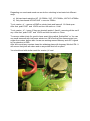
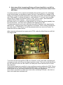
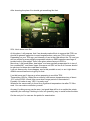
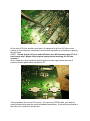
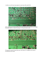
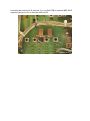
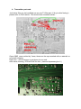
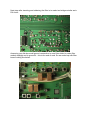
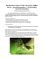
Modification Yaesu FT-847 dla pasma 70MHz Part II – practical solution v. 1.0 (Oct 2013) Greg SP3RNZ [email protected] PA mod idea by Marc PA1O TX/RX mod idea by Hellar ES1II/8 This article describing how to do modification of your RIG in practice. Theoretical aspect were described in previous part of the article about modifying Yaesu FT847 RX/TX filters to get all we can have from this nice radio. Because You probably read part first before ( if not – I insist You should!) I will focus on practical aspect of the mod. The job we need to do is: - unlocking the radio, if it’s still locked to gain access to 4m, - remove capacitor in PA module to increase TX efficiency - replacing existing RX Bandpass filter to modified one with LNA, - replace existing TX filter chain to sharper one to get clean signal. Let’s get it started ;-) 1. Unlocking your FT847 to get 4m ( for those who already have unlocked one, please move to chapter 2). Assuming we have fresh one locked 847 on the workbench we should start with make it alive on 4m. Job is easy, and should not take long time even if You haven’t much electronic experiences. First unscrew top and bottom cover, and turn the radio upside down. If You have Your radio facing with the main tunning knob facing You, look on the left upper corner. There is Lithium battery, and on the left You will see six solder points marked 1-6 . They could be just shortened by solder, or small SMD 0Ohm resistors. On the picture You can see factory state unmodified 847. Regarding our needs and mood we can do the unlocking in two basic but different ways. a) No ham band restriction HF 1,8-76MHz, VHF 137-174MHz, UHF 410-470Mhz b) Only ham bands HF/VHF/UHF + new one 70Mhz. To do version „a” – remove all SMD or solder joints and leave all 1-6 fields open. After that, push FAST and LOCK and turn the radio on. Voila! To do version „b” – leave (if they are shorted) points 1,2and 6, removing all the rest if any. After that, push FAST and LOCK and turn the radio on. Done. To remove solder joints it’s good to have smart thing called „SolderWick” or You can use small tweezers with low power solder iron. BE sure that You disconnected your solder from mains, before start. As we are working around Memory and uPC is good to Pay attention to ESD. After all to avoid any suprises clean the soldering place with Isopropyl Alcohol IPA. It will ensure that joints are clean and no any solder dust left on place. You should end with similar result for version „b” mod. 2. Next step will be increasing efficiency of Power Amplifier in our 847 by applying mod described by Marc PA1O in his superb article about Yaesu 847 filters. I’m pretty sure few of You experienced already that unlocking gives You advantage to get into 4m band, but big power supply is a must. It’s mostly due to design of the filters in PA stage and spurs produced in early stage of TX chain transmitted together with 70Mhz signal. In almost all tested (4 until now) 847 TX current was very high, despite low TX power and reaches even 17A by 10 W of output ( last tested 847 reached 26A by 30W of power – really amazing efficiency ) But better don’t try to transmit for longer period, you can get new # and possibly few burned elements... and then some troubles with repairing your 847. To get the transmitter much more efficiently we must do another mod, described by Marc PA1O – removing one of the capacitor in PA board. This is exactly described in his article about FT847 filters, but will be presented also here more as “how-to” for those who did not read it before. After removing all screws from upper part of TRX, under the Main Board we will find PA stage board. To do the mod we must pull the PCB out of chassis, so let’s start with unscrewing all necessary screws, all of them including transistor screws. Then we should disconnect two HF outputs on the rear. Be careful, as these pins need to be bend a bit to suck the solder out. At this point please look carefully for two small bronze spring soldered to PCB. This is additional ground, and it’s nothing exceptional in them, except they are soldered with small amount of tin, and likes to broke from PCB and jump somewhere. As we don’t need them to make short circuit after mounting PCB back– take look on them and make them soldered well. After PCB removal ( no need to disconnect any cables, just gently pull the PCB back and lift it up, and rotate upside down ) we need to locate two capacitors located near PA transistors marked Q2 and S2. We will remove this one marked S2. Marc PA1O concluded that Yaesu applied strong glue, Yep. In fact they used very strong one, and this can make capacitor removal bit tricky, as it can’t be just warmed and desoldered. The best idea is to suck the tin on each side (i.e using smart thing like “solderWick” tape by Chemtronics) and use small tweezers to catch the capacitor and turn him gently applying some heat together. Warming the capacitor with more heat or bigger soldering iron will not help, as this is silver mica one spreading the heat around on PCB, and will not move as standard SMD device. More heat can only burn the track, and/or PCB itself. After removing You will probably see that bottom side of cap is still on PCB, but that’s is easy to solve. You can remove this with sharp knife. Just apply small drop of IPA alcohol at the place where cap was fitted, letting IPA penetrate under the capacitor foil. Then use solder at the one solder point and try to lift the foil in the middle. It will easy move up then, leaving only small Japanese mega strong glue. (Tested on two different 847). After cleaning the place You should get something like that: 50% Job is done now. But. At this place, I will propose, that if we already made efforts to remove this PCB, we should do general inspection to avoid suprises when using our TRX in the future. Depending on your TRX age, and intensity of use in the past without the TX mod you will see melted or even partially evaporated solder on SMD capacitors and legs of toroidal colis in filter stage! There’s the place where famous L5022 is. More less, I did found these „heat signs” and even partially evaporated tin in two of four modded 847, and these clean ones were not QRV on 4m at all. Answer should be obvious for those who read Marc’s articles. I will not discuss why it was happen, and is this possible or not, or am I right about 45MHz second harmonics is guilty for that. I just did some test 2 days a go when preparing to mod this TRX. Transmitting 15W for 10minutes on dummy load causes temperature rise of about 10°C at the L5022. Would it be more when longer period of transmission? Possibly. Or better to say: YES. I’m pretty sure. Whatever the cause really is, there’s no significant temperature rise after TX filter mod. You can make conclusion yourself. Anyway if nothing wrong can be seen, just good idea will be to re solder the points, especially the coils legs. Nothing to lose, but (possibly) way to avoid further troubles. On the next pic You can see the points for examination. At the end of PA job, another good idea. As observed in all four 847 after some (years) of time beryllium oxide paste used as heat spreader on transistors is getting dry and hard. NOTE: I found that in 847 year model 8G there was NO thermal paste AT ALL – hard to say why? Maybe they forgot to apply before inserting the PA into chassis? All we need is to clean transistor places and their base, apply small amount of ceramic thermal paste same as used in PC. This operations will end our PA survey. You can mount PCB inside, just observe small ground spring near the main broadband transformer. It should be positioned in the way not to touch the nearest coil. 3. Receiver part mod. With radio in standard position facing us, we need to unscrew the filter board. Before lift up, be sure that You disconnected Red and Yellow mini coax connectors. After removing PCB we will have access to TX and RX filters. To do this mod we must remove almost all SMD capacitors and coils. Which one? Look at the picture – part of service manual. It will be easier to find them if You look on upper side of PCB and find two known green coils marked L3024 and L3029 (could be that these green chokes are hidden under the interconnection cables): Start with desoldering these green ones, with the help of sharp knife lift the leg up and bent it opposite way. After removing all remaining elements it’s good to clean the place with IPA alcohol. In effect, we will have clean place to mount new filter with LNA. After inserting and soldering filter module we need only to make two wire bridges from diode switch to make it working. It’s clearly shown below. Of course it’s good to check with any multi meter if no sudden short circuits accidentally were made. Last thing we need to do is connect +Vcc on filter PCB to nearest SMD 22uF capacitor giving us +8V to feed the LNA on RX. 4. Transmitter part mod. Just below filter we Just modified we can see TX filter part. If Any trouble finding it, please refer to PA1O article. This should look somehow similar. Green SMD were omitted by Yaesu, those are the caps marked with an asterisk on schematic diagram. Red ones – we will remove to get place for our mod. After some cleaning, PCB will look like this. ( damned Japanese glue ) Next step after inserting and soldering the filter is to make two bridges similar as in RX chain: Assuming you did also small ground connection to near filter shield to make filter module straight and to ground it - this is the end of mod. So we ended up with filter board looking like below. You can mount the PCB in the chassis, connect all remaining cables and connectors and be happy with your FT847. Please be careful when You cover the upper shield with speaker. Sometimes You will need to turn the speaker around to move audio soldering points to another position avoid short circuit with filter board. There’s not much place to do anything, and we just added two small but PCB. If the speaker will be to close with filter PCB you can bent the RX PCB toward front of the radio. It will increase the space between the speaker and filter PCB and it will fit OK. Note : Although I am sure that this mod is repeatable, and anyone can get similar parameters, final result depends on fact if there was any attempt to modify RX gain. It will be good to get into service menu of the RIG and check RX-CHAIN parameter and correct the gain if needed. Standard Hex note for RX-CHAIN parameter is Something like 3E for model 9I and 4E for earlier 8G. The lower Hex, the lower gain. Disclaimer: This article is written for information purposes only. Although all described mods were carefully tested myself on my own radio, back and forth in the period of last year of my activity on 4m, I shall not be judged responsible for any damages/failures of your transceiver, if something will go wrong. All mod’s you just doing on your own responsibility. If You are not sure You can do it yourself, better ask a friend. Or if You want to push more life in your 847 and you don’t know how, write me. We are living on the same planet Sincerely thanks for Marc PA1O, for his super job, and Hellar ES1II with Arvo ES1CW for many hints about 847 mods and Jacek SP3LYU for loan me his FT847 to do the mods. Best DX DX, 73 Greg SP3RNZ Oct.2013