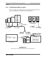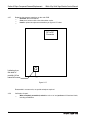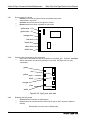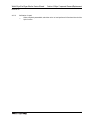
1
Manuals
Service Manual
Service Manual
Welch Allyn
Vital Signs Monitor
Medical Division
4341 State Street Road, P.O. Box 220
Skaneateles Falls, NY 13153-0220
PN 95P360E
Copyright 1996
Welch Allyn Vital Signs Monitor Service Manual
Revision 4.0
SECTION 1:
General Information
SERVICE MANUAL
Welch Allyn
Vital Signs Monitor
Copyright 1996
Welch Allyn Co.
4341 State Street Road
Skaneateles Falls, NY 13153-0220
Service Manual pn95P360E
Rev. 4, 9/98
Welch Allyn Vital Signs Monitor Service Manual
Revision 4.0
*Note: All drawings enclosed are for reference only. Consult the system or the factory for all current drawings.
Revision History
Revision
Sections
Date
Author
Description
1.00
2.00
All
All
4/18/96
7/9/96
JDB/RJS
JDB
3.00
All
5/28/97
JDB
4.00
All
10/1/98
JDB
Introduction of manual.
Revision made due to
problems found in training
and changes to the repair
software.
Revisions made for
support of Nellcor SpO2
module.
Added schematics, board
layouts and bill of
materials, miscellaneous
corrections.
Welch Allyn Vital Signs Monitor Service Manual
Revision 4.0
Table Of Contents
SECTION 1:
General Information
Sub-Section:
To Service Personnel ................................................
1.1
Limited Warranty/Warranty Assistance .....................
1.2
Basic System Description ..........................................
1.3
Basic System Operation Index ..................................
1.4
Basic System Operation ............................................
1.4
Block Diagram of Unit Operation ...............................
1.5
Specifications ............................................................
1.6
Serial numbering system defined ..............................
1.7
Firmware Identification ..............................................
1.8
SECTION 2:
Service Set Up
Service Manual Intent & Scope .................................
Test Equipment Bench Layout ..................................
Required Tools/Equipment List .................................
Replacement Parts List .............................................
Maintenance/Service Support ...................................
2.1
Fig 2.2.1
2.2.2
2.3
2.4
1
3-4
5
7-9
11
Problem Diagnosis
Overview ...................................................................
Diagnostic Process/Returned units ...........................
When and how to calibrate ........................................
Loading Unit Software ...............................................
Welch Allyn Monitor Self Diagnostic Fault Codes .....
“Complaint/Cause/Corrective Action” ........................
3.1
3.2
3.3
3.4
3.5
3.6
1
3-5
7-8
9
11-13
15-19
Major Component Removal/Replacement
(IN ORDER OF REMOVAL ACCESS)
Front Housing ............................................................
Main Fuse F1 on Main PCB ......................................
Main Printed Circuit Board (PCB) ..............................
DC TO DC Converter (SpO2 units) ............................
Pressure Transducer on Main PCB ...........................
Display PCB ..............................................................
Key Pad (front housing) .............................................
Temperature PCB .....................................................
Specific Oxygen Board (Nonin) .................................
Specific Oxygen Board (Nellcor) ...............................
Pump .........................................................................
Pressure Switch MPL-503 .........................................
Valve (Pneutronics) ...................................................
Printer/Printer PCB/keypad .......................................
Battery .......................................................................
4.1
4.2
4.3
4.4
4.5
4.6
4.7
4.8
4.9
4.10
4.11
4.12
4.13
4.14
4.15
1-2
3-4
5-6
7-8
9-10
11-12
13-14
15-16
17-19
21-22
23-24
25-26
27-28
29-30
31-32
SECTION 3:
SECTION 4:
Page:
1
3-4
5
7
8-14
16-17
19-23
25
27
Welch Allyn Vital Signs Monitor Service Manual
Revision 4.0
SECTION 5:
Test Procedures
Sub-Section:
Calibration test ..........................................................
5.1
Current tests .............................................................
5.2
Noise test..................................................................
5.3
Button Test ...............................................................
5.4
Print quality ...............................................................
5.5
Pneumatic test ..........................................................
5.6
Hardware Fail-safe Tests .........................................
5.7
5.8
SpO2 option testing ...................................................
Temperature option testing .......................................
5.9
Check List for CBPM Service Work ..........................
5.10
SECTION 6:
Drawings, Schematics, Board Layouts, Bill of Materials
SECTION 7:
Repair Test Specifications
Specifications ...........................................................
7.1
Page:
1-2
3
5
7
9
11-12
13
15
17
19-20
1-5
CAUTION: PRIOR TO DOING REPAIR WORK, USE GROUNDING MAT AND
ANTI-STATIC WRIST STRAP TO MINIMIZE RISK OF DAMAGE TO SENSITIVE
ELECTRONIC COMPONENTS.
Welch Allyn Vital Signs Monitor Service Manual
Section 1: General Information
Revision 4.0
1.1 To Service Personnel:
Read and understand the Welch Allyn Vital Signs Monitor Operator Manual and this Service
Manual. The information contained in both of these publications is subject to change without
notice and should not be construed as a commitment by Welch Allyn, Inc.
Welch Allyn assumes no responsibility for any errors that may appear in this manual. If the
product and/or its operation varies significantly from any description herein, please contact the
WELCH ALLYN TECHNICAL SERVICE DEPARTMENT:
1-800-450-9275
(828) 684-4895
Fax (828)687-9323
Welch Allyn, Inc.
95 Old Shoals Road
Arden, North Carolina 28704
This product has been designed to provide a high degree of safety and reliability. However, we
can not guarantee against: deterioration of components due to aging, normal wear, tampering,
and abuse.
All service and repairs must be performed by authorized Welch Allyn personnel or agents, using
approved Welch Allyn replacement parts and approved process materials. Failure to so will
invalidate the product warranty. Please refer to the product warranty for specific coverage.
Welch Allyn, Inc.
95 Old Shoals Road
Arden, North Carolina 28704
USA
1 800 450-9275
CAUTION WHEN USING ADHESIVES:
ALWAYS WEAR SAFETY GLASSES AND PROVIDE ADEQUATE VENTILATION WHEN USING
ADHESIVES, THEIR ACCELERATORS AND RTV SEALANTS. READ, UNDERSTAND, AND COMPLY
WITH SAFETY RECOMMENDATIONS IN THE MATERIAL SAFETY DATA SHEET MSDS) FOR THESE
MATERIALS. SUPER-GLUES (CA ADHESIVES) CAN CAUSE CORNEAL DAMAGE IF ACCIDENTLY
SQUIRTED IN THE EYES, AND CAN SPONTANEOUSLY COMBUST IF SPILLAGE IS WIPED UP WITH
CLOTH OR PAPER TISSUES. READ THE WARNINGS AND CAUTIONS PRINTED ON THE BOTTLES OR
TUBES OF THESE GLUES!
1
Welch Allyn Vital Signs Monitor Service Manual
Section 1: General Information
Revision 4.0
1.2 Limited Warranty
Welch Allyn warrants the Welch Allyn Vital Signs Monitor, when new, to be free
of defects in material and workmanship and to perform in accordance with
manufacturer’s specifications for a period of two years from the date of purchase
from Welch Allyn or its authorized distributors or agents. Welch Allyn will either
repair or replace any components found to be defective or at variance from
manufacturer’s specifications within this time at no cost to the customer. It shall
be the purchaser’s responsibility to return the instrument to Welch Allyn or an
authorized distributor, agent or service representative. This warranty does not
include breakage or failure due to tampering, misuse, neglect, accidents, modification or shipping. This warranty is also void if the instrument is not used in
accordance with manufacturer’s recommendations or if repaired by other than
Welch Allyn or an authorized agent. Purchase date determines warranty requirements. No other express warranty is given.
To receive service assistance or to ask questions regarding this warranty, please call or write:
Welch Allyn Technical Services Dept.
95 Old Shoals Road
Arden, North Carolina 28704 USA
1 (800) 450-9275 or (828) 684-4895
Fax: (828) 687-9323
Service Policy
All repairs on products under warranty must be performed or approved by a Welch Allyn
Service Center. Unauthorized repairs will void the warranty. Products out of warranty
should be repaired by qualified electronics personnel or a Welch Allyn Service Center.
Technical Assistance
If you have an equipment problem that you cannot resolve, call the Welch Allyn Service
Center nearest you for assistance. Technical service support is available to you by telephone on normal business days, from 8:30AM until 4:30PM Eastern Standard Time at the
phone numbers listed on the next page.
3
Section 1: General Information
Welch Allyn Vital Signs Monitor Service Manual
Revision 4.0
Before returning a product for repair you must obtain authorization from Welch
Allyn. An RGA (Return Goods Authorization) number will be given to you by our
service personnel. Be sure to note this number on the outside of your shipping
box. Returns without an RGA number will not be accepted for delivery.
Welch Allyn Service Centers
For Service or Repair
USA Customers
Welch Allyn, Inc.
Technical Service Centers
95 Old Shoals Road
Arden, NC 28704-9739 USA
Phone: 828-684-4895
Fax: 828-687-9323
CANADA Customers
Welch Allyn Canada Limited
Technical Service Centers
160 Matheson Blvd., East
Mississauga, Ontario L4Z1 V4 CANADA
Ph: 905-890-0004 or 1 800-561-8797
Fax: 905-890-0008
INTERNATIONAL Customers
Welch Allyn GmbH
Technical Service Center
Zollerstrasse 2-4 Road
D-7241 7 Jungingen
GERMANY
Phone: [49]-7477-9271-73
Fax: [49]-7477-9271-93
Welch Allyn Australia Pty. Ltd.
Technical Service Center
Ground Floor, 18-20 Orian Road
Lane Cove NSW 2066
AUSTRALIA
Phone: [61]-29-4183-155
Fax: [61]-29-4183-650
Welch Allyn Ltd.
21-09 Golden Mile to 6001
Beach Road
Singapore 199589
REPUBLIC OF SINGAPORE
Phone: [65]-29l-0882
Fax: [65]-291-5780
LATIN AMERICA Customers
MDI International
Technical Service Centers
7324 SW 48th Street
Miami, FL 33155 USA
Phone: 305-669-9591
Fax: 305-669-l 971
4
Welch Allyn \N!!
Welch Allyn Vital Signs Monitor Service Manual
Section 1: General Information
Revision 4.0
1.3 Basic System Description
Introduction
The Welch Allyn Vital Signs Monitor is designed to non-invasively and
automatically measure systolic and diastolic pressure, pulse rate, temperature and oxygen saturation (SpO2) for adult and pediatric patients. All pressure, pulse, temperature and SpO2 values are displayed on large, easy-toread displays, and may be printed via an integrated thermal printer, as
desired.
The rechargeable battery and wide variety of mounting accessories make
the Clinical Monitor convenient for many locations. The operator may
choose any combination of simultaneous measurement modalities. This
flexibility, combined with features such as programmable alarms and automatic BP cycles, makes the Clinical Monitor ideal for a wide variety of patient monitoring needs.
Refer to the Operator Manual PART NUMBER 5200-85 (SPECIFY LANGUAGE) Section 1 for complete information on Indications For Use, Special
Features, Supplies and Accessories
5
Welch Allyn Vital Signs Monitor Service Manual
Section 1: General Information
Revision 4.0
1.4 Basic System Operation
INDEX
1.5.1 Blood Pressure Operating Modes
a. Max/Min Blood Pressure and Pulse Ranges
b. Blood Pressure Manual Mode
c. Blood Pressure Auto Mode
1.5.2 Temperature Operating Modes
a. Max/Min Temperature Ranges
b. Temperature Normal Mode
c. Temperature Monitor Mode
1.5.3 SpO Operating Mode
2
a. Max/Min SpO2 Ranges
b. SpO2 Monitor Mode
1.5.4 Pulse Rate Feature
Max/Min Pulse Rate Ranges
7
Section 1: General Information
Welch Allyn Vital Signs Monitor Service Manual
Revision 4.0
1.4.1 Blood Pressure Operating Modes
When a blood pressure measurement cycle is initiated, the cuff will automatically be
inflated to the operator selected pressure level.
The cuff will immediately begin to deflate in a stepped fashion and will determine systolic
pressure and diastolic pressure from the pulses sensed by the cuff at various pressure
levels. This is the oscillometric method of non-invasive blood pressure monitoring.
Blood pressure measurements may be initiated manually, or automatically at time intervals determined by the user.
At the completion of a measurement cycle the systolic and diastolic pressures are displayed. If the Monitor is in Automatic Mode, the measured values are kept on display until
the next BP measurement is initiated. When not in Automatic Mode, the measured values are displayed for two minutes, after which time the display screen is blanked. The
most recent BP measurement may be recalled by pressing the REVIEW button.
When in Automatic Mode, if the unit is unable to determine the systolic or diastolic value,
the measurement will be automatically repeated once.
1.4.1.a. Max/Min Blood Pressure Ranges
The maximum and minimum ranges of blood pressure are detailed below:
Measurement
Maximum
Minimum
Systolic Pressure
250 mmHg
60 mmHg
Diastolic Pressure
160 mmHg
30 mmHg
8
Welch Allyn Vital Signs Monitor Service Manual
Section 1: General Information
Revision 4.0
1.4.1.b. Blood Pressure Manual Mode
In the Manual Mode, a single blood pressure determination is made only when the
START button is pushed. The manual mode is the default mode of operation for blood
pressure determinations.
A measurement cycle may be canceled at any time by pressing the CANCEL button.
This action immediately initiates a rapid cuff deflation.
The blood pressure measurement data will appear on the display immediately following
the measurement. The display will blank after two minutes. If the display is blanked,
pressing the REVIEW button on the front panel will recall the measurement. Up to 99
prior measurements are available for review or printing.
In Blood Pressure Manual Mode, the following alarm limits may be activated; SYSTOLIC
HIGH LIMIT, SYSTOLIC LOW LIMIT, DIASTOLIC HIGH LIMIT, DIASTOLIC LOW LIMIT,
PULSE RATE HIGH LIMIT and PULSE RATE LOW LIMIT. Blood pressure determinations which activate alarms are indicated by flashing displays and a repetitive audible
tone. If an alarm limit is violated, subsequent blood pressure determinations may be
made only after the alarm condition is reset by pressing any button on the Monitor’s
display.
1.4.1.c. Blood Pressure Automatic Mode
The Automatic Blood Pressure Mode is entered by pressing the AUTO button. Pressing
the AUTO button displays a choice of 10 cycle interval times as follows: “st” (STAT mode)
3 min, 4 min, 5 min, 10 min, 15 min, 30 min, 45 min, 60 min and 90 min. These choices
represent the time interval from the beginning of one cycle to the beginning of the next
automatic cycle. STAT mode allows the monitor to take continuous blood pressure measurements for 15 minutes. In addition, the operator may choose to disable the Auto Mode
by choosing “—” (two dashes).
A measurement cycle may be canceled at any time by pressing the CANCEL button.
This action immediately initiates a rapid cuff deflation.
The blood pressure measurement data will appear on the display immediately following
the measurement and will remain displayed until the next measurement cycle is initiated.
9
Section 1: General Information
Welch Allyn Vital Signs Monitor Service Manual
Revision 4.0
1.4.1.c. Blood Pressure Automatic Mode continued
In Blood Pressure Auto Mode, the following alarm limits may be activated; SYSTOLIC
HIGH LIMIT, SYSTOLIC LOW LIMIT, DIASTOLIC HIGH LIMIT, DIASTOLIC LOW LIMIT,
PULSE RATE HIGH LIMIT and PULSE RATE LOW LIMIT. Blood pressure determinations which activate alarms are indicated by flashing displays and a repetitive audible
tone. Any alarm limit violation must be reset to continue automatically timed blood pressure determinations. The alarm may be reset by pressing any button on the monitor’s
display.
1.4.2. Temperature Operating Modes
Thermistor Thermometry measurements are made with the DIATEK/Welch Allyn
SureTemp4TM thermometer. Oral and rectal probes utilize single-use disposable probe
covers which limit cross-contamination. Oral or rectal temperatures are taken using
‘Normal’ or ‘Monitor’ operating modes. Auxiliary temperatures may be taken using the
oral probe in the monitor operating mode.
In the normal mode the thermometer’s microprocessor “predicts” body temperature in
about 4 seconds for oral temperatures and in about 15 seconds for rectal temperatures.
The monitor mode displays the patient’s actual temperature after 3 minutes and will
continue to display an updated temperature as long as the probe remains in place.
Temperature readings may be displayed in Fahrenheit or Celsius scales.
1.4.2.a. Max/Min Temperature Ranges
Readings
Normal Mode
Monitor Mode
Temperature
Max 108.0F
Max 42.2C
Max 108.0F
Max 42.2C
Min 84.0F
Min 28.9C
Min 84.0F
Min 28.9C
10
Welch Allyn Vital Signs Monitor Service Manual
Section 1: General Information
Revision 4.0
1.4.2.b. Temperature Normal Mode
In Normal Mode, the device will measure temperature at discrete intervals and then
calculate the rate of change according to a known algorithm. This allows the thermometer to predict the end point that the thermistor would reach if it were left in the mouth until
it reached mouth temperature. This predictive feature allows the thermometer to arrive at
an accurate oral temperature reading in approximately 4 seconds.
Normal mode is the default operating mode for temperature determinations.
Operator selectable patient alarm limits are not available in Temperature Normal
Mode. However, temperatures which are outside of the operating range of the
device will be noted on the temperature display.
1.4.2.c. Temperature Monitor Mode
Continuous Monitor Mode operation is normally used for longer term monitoring and
when difficult situations prevent accurate temperatures from being taken in the normal
mode. The probe must be in contact with tissue for at least three (3) minutes for accurate
temperature measurement. Monitor mode temperatures may not be identical to predicted
‘Normal’ temperatures because of ambient temperature influence and other factors. The
trend in temperature is the important standard to be observed when in the ‘Monitor’ mode.
Operator selectable patient alarm limits are not available in Temperature Normal
Mode. However, temperatures which are outside of the operating range of the
device will be noted on the temperature display.
11
Section 1: General Information
Welch Allyn Vital Signs Monitor Service Manual
Revision 4.0
1.4.3 SpO2 Operating Mode
The Welch Allyn Vital Signs Monitor incorporates either the Nonin® pulse oximetry system
or the Nellcor® pulse oximetry system which determines arterial oxyhemoglobin saturation
(% SpO2) by measuring the absorption of red and infrared light passed through the tissues. Changes in absorption caused by pulsation of blood in the vascular bed are used
to determine arterial saturation and pulse rate.
Oxygen saturation percent is calculated with each pulse detected, and thus the monitor
display is continually updated. The pulse signal bar graph is an indicator of the strength
and quality of the detected pulses.
When SpO2 is measured, the patient’s pulse rate is also measured and displayed. A
pulse rate measurement from the SpO2 determination overrides a pulse rate measurement derived from a blood pressure measurement.
In SpO2 monitoring mode operator selectable alarm limits for low SpO2 % may be activated. A condition which violates the SpO2 low limit alarm is indicated by a flashing
display and repetitive audible tone. Should a patient alarm condition for ≤ or pulse rate
occur, the Monitor will indicate an alarm condition (flashing & beeping) while continuing to
monitor and display the patient’s current SpO2%. The alarm will automatically reset when
the patient’s condition returns to within the preset alarm parameters.
Should a patient alarm condition for SpO2 or pulse rate occur, the operator may invoke
“Silence Mode” by pressing the SILENCE button. This will silence the audible tone
(display will continue to flash), while the practitioner attends to the patient and the monitor. Silence mode resets automatically after 30 seconds, or when the patient’s condition
returns to within the preset alarm parameters.
Removal of the SpO2 sensor from the patient will initiate an alarm. To reset the sensor
alarm, press any button on the monitor’s display.
SpO2 is generally measured via pulses detected using a finger sensor. However, for
certain situations SpO2 may be measured at alternate sites including the earlobe, forehead and toes. Special sensors must be employed in these situations.
12
Welch Allyn Vital Signs Monitor Service Manual
Section 1: General Information
Revision 4.0
1.4.3.a. Max/Min SpO2 Ranges
The SpO2 sensor is designed to detect oxygen saturation as follows.
Maximum
SpO2
99%
Minimum
40%
1.4.3.b. SpO 2 Monitor Mode
The SpO2 monitor performs most accurately with the finger clip sensor, which may be
used on all fingers except the thumb. The finger clip sensor is recommended for spot
checks or short term (<30 minutes) continuous monitoring.
The device determines arterial oxyhemoglobin saturation (SpO2 %) by measuring the
absorption of red and infrared light passed through the tissue. Oxygen saturation and
pulse rate are displayed on the LED digital display. On each detected pulse, the pulse
signal bar graph flashes. The intensity of this signal is a simple visual indicator of waveform signal strength, and can identify situations where the pulsatile nature of the tissue
may not be adequate for an accurate SpO2 reading. The update interval of the bar graph
should correspond to the patient’s pulse rate. This is an indication of the quality of the
SpO2 signal.
1.4.4 Pulse Rate Feature
The Welch Allyn Vital Signs Monitor is capable of determining pulse rate as an adjunct to
the blood pressure measurement and the SpO 2 measurement.
The pulse rate, in beats per minute, will be determined primarily from the SpO2 measurement
methodology. In the case where SpO2 is not available, or is disabled, the pulse rate display
will be driven from data collected as part of the blood pressure measurement method.
There are two operator selectable alarm limits for the pulse rate. They are PULSE RATE
HIGH LIMIT and PULSE RATE LOW LIMIT. Pulse rates which activate alarm limits are
indicated by a flashing display and a repetitive audible tone.
Should a pulse rate alarm occur when the pulse rate measurement is derived from the
blood pressure measurement, no subsequent blood pressure or pulse rate measurements
may be made until the alarm is reset. The alarm may be reset by pressing any button on
the monitor’s display.
13
Section 1: General Information
Welch Allyn Vital Signs Monitor Service Manual
Revision 4.0
Should a pulse rate alarm occur when the pulse rate measurement is derived from the
SpO2 measurement, the monitor will indicate an alarm condition (flashing & beeping)
while continuing to monitor and display the patient’s current SpO2% and pulse rate. The
alarm will automatically reset when the patient’s condition returns to within the preset
alarm parameters.
Should a patient alarm condition for pulse rate occur during SpO2 monitoring, the operator may invoke “Silence Mode” by pressing the SILENCE button. This will silence the
audible tone (display will continue to flash), while the practitioner attends to the patient
and Monitor. Silence mode resets automatically after 30 seconds, or when the patient’s
condition returns to within the preset alarm parameters.
1.4.4.a. Max/Min Pulse Rate Ranges
The maximum and minimum pulse rate ranges are as follows:
Pulse Rate
14
Maximum
200 bpm
Minimum
40 bpm
Welch Allyn Vital Signs Monitor Service Manual
Section 1: General Information
Revision 4.0
Figure 1.5 Block Diagram of Unit Operation
Yes
Is Start
➤ Is Power Button Yes ➤
Is Cancel
Yes
➤ Button Pressed?
Button
Pressed?
Pressed?
No
No
No
➤
Off
➤
D
➤
➤
➤ C
Post
F2
➤
➤
➤ F1
Ready State
➤ Start
No
➤
➤
Reset
Display
➤
➤
➤
Is Select
Pressed?
Yes
No
Record Setting
for Displayed
Alarm
➤
Yes Any button than
auto select?
No
Is
10
sec.
Yes
since last
action?
No
➤
➤
➤
➤
➤
Display
Next Setting?
No
Display
Next
Setting?
➤
➤
➤
➤
➤
➤
➤
Is Auto
Pressed?
Yes
➤
➤
➤
➤
➤
➤
➤
Yes
➤
Record
Setting
Is Adjust
Pressed?
No
➤
➤
➤
Is 10 sec.
since last
action?
No
No
Display Current
Timer Setting
Reset
Display
Yes Any button than
review select?
No
Yes Any button than
adjust select?
No
Is 10 sec.
Yes since last
action?
No
➤
➤
16
Record
Setting
➤
➤
Display Last
Reading
Display
Next RDG?
Display Current
Setting of 1st Alarm
➤
➤
Silence Alarm
for 30 Seconds
Is Reading
Finished?
No
➤ M1
M2
➤
Is Cancel
Pressed?
No
Is Review
Pressed?
Yes
➤
Is Alarm
Activated?
Yes
Reset
Display?
Yes
Mode
➤
➤
Select
➤
➤
Yes
Auto
➤
➤
➤
Silence
➤ P2
➤
➤
Yes
Print
Review
Start Taking
Reading
➤ P1
Feed
Power
Display Next Alarm
@ Current Setting
➤
Welch Allyn Vital Signs Monitor Service Manual
Section 1: General Information
Revision 4.0
M1
➤
Both BP and SpO2
module active
F2
Print
Report
F1
Advance Paper
One line
➤
BP module
active, SpO 2
module inactive
P1
➤
➤
➤
P2
➤
M2
➤
Figure 1.5 Block Diagram of Unit Operation
Review advances to next box
Power returns to “O” at any time
Cancel resets changes
D
➤
Post
➤
➤
SpO2 module
active, BP
module inactive
Show Versions
Print produces version report
C
➤
Calibration
Start closes valve
Cancel opens valve
Auto runs pump while pressed
Post
➤
Show Versions
Print produces version report
➤
➤
Battery Voltage
Start closes valve
Cancel opens valve
Auto runs pump while pressed
➤
Calibration
Start closes valve
Cancel opens valve
Auto runs pump while pressed
➤
Temp Module Setup
Adjust changes setup
➤
Battery Voltage
Start closes valve
Cancel opens valve
Auto runs pump while pressed
➤
Set Date
Adjust changes flashing display
Select makes next display flash
➤
Temp Module Setup
Adjust changes setup
➤
Set Time
Adjust changes flashing display
Select makes next display flash
Set Date
Adjust changes flashing display
Select makes next display flash
➤
➤
➤
➤
➤
Review advances to next box
Power returns to “O” at any time
Cancel resets changes
A/D Channel Noise
Select changes A/D channels
RS232/Service Port Test
SpO2 perfusion signal - systolic
display, display perfusion status
Life Test
Start begins cycling
Cancel halts cycling
➤
Set Time
Adjust changes flashing display
Select makes next display flash
➤
➤
17
Welch Allyn Vital Signs Monitor Service Manual
Section 1: General Information
Revision 4.0
1.6 Specifications
Index:
1.6.1
Performance Specifications
1.6.2
Technical Specifications
a. Mechanical Specifications
b. Electrical Specifications
c. Environmental Specifications
1.6.3
Printer Specifications
1.6.1 Performance Specifications
The performance specifications of the Clinical Vital Signs Monitor are as follows:
CUFF PRESSURE RANGE
0 mmHg - 300 mmHg
INITIAL CUFF INFLATION
120 mmHg, 140 mmHg, 160 mmHg, 200 mmHg, 240 mmHg or 280 mmHg depending on
pressure preset level.
SYSTOLIC DETERMINATION
Maximum: 250 mmHg
Minimum: 60 mmHg
DIASTOLIC DETERMINATION
Maximum: 160 mmHg
Minimum: 30 mmHg
BLOOD PRESSURE ACCURACY
Blood pressure accuracy meets or exceeds SP10-1992 AAMI standards for non-invasive
blood pressure accuracy (AAMI standard: ± 5 mmHg mean error; 8 mmHg standard
deviation). Blood pressure accuracy is validated for pressure measurement using the
upper arm only.
BLOOD PRESSURE DETERMINATION TIME
20 seconds to 45 seconds typical, 140 seconds maximum.
19
Section 1: General Information
Welch Allyn Vital Signs Monitor Service Manual
Revision 4.0
PULSE RATE DETERMINATION
Maximum: 200 bpm
Minimum:
40 bpm
PULSE RATE ACCURACY
SpO2 Module Heart Rate
Blood Pressure Algorithm Heart Rate
±3.0%
±5.0%
OVERPRESSURE CUTOFF
295 mmHg to 330 mmHg
TEMPERATURE DETERMINATION
Normal Mode
Maximum
Minimum
Monitor Mode
Maximum
Minimum
108.0F (42.2C)
84.0F (28.9C)
108.0F (42.2C)
84.0F (28.9C)
TEMPERATURE ACCURACY
Temperature accuracy meets ASTM E112-86: “Standard Specification for Electronic
Thermometer for Intermittent Determination of Patient Temperature.”
TEMPERATURE DETERMINATION TIME
Normal Mode: ORAL: 4 seconds typical, 15 seconds maximum
Monitor Mode: ORAL: 3 minutes.
OXYGEN SATURATION RANGE (SpO2%)
40-99% oxygen saturation
SpO2 ACCURACY
±3% in the range of 70-99% oxygen saturation (1 Standard Deviation)
BATTERY CHARGING
To at least 90% capacity in 12 hours. Unit will operate and charge battery simultaneously
when connected to power source.
20
Welch Allyn Vital Signs Monitor Service Manual
Section 1: General Information
Revision 4.0
1.6.2 Technical Specifications:
1.6.2.a Mechanical Specifications
Dimensions
Height
Length
Depth
6.5 inches
8.6 inches
5.0 inches
(16.5cm)
(21.8cm)
(12.7cm)
Weight
Approximately 6 pounds (2.8Kg)
Color
Oral Temperature Probe - Blue
Rectal Temperature Probe - Red
Mounting
Self-supporting on rubber feet
IV Pole Mountable
Custom Mobile Stand
Wall Mountable
Attaches to Bed Rail
Portability
-May be hand carried when held by the recessed handle.
-When attached to an IV pole, or mounted on its custom mobile stand, the monitor
and accessories can be wheeled from patient to patient.
-When attached to the bed rail may be transported with the patient within the
hospital environment.
Operator Instructions/Alarm Interpretation
Comprehensive Operator Manual available. Quick reference operator instructions and
alarm interpretation are located on side panel labels.
21
Welch Allyn Vital Signs Monitor Service Manual
Section 1: General Information
Revision 4.0
1.6.2.b Electrical Specifications
Power Requirements
Patient-Rated isolation transformer is connected to AC mains:
North American Version
120VAC, 60 Hz.
International Versions:
220-240VAC, 50-60Hz.
Battery
6 v, 4 Ahr / 20 hr Sealed Rechargeable Lead Gel Cell
A fully charged battery will support 200 “typical” blood pressure determinations taken at 3
minute intervals (10 hours). Battery is 90-100% charged after 12 hours of charging. The
battery automatically charges when the monitor is powered through the AC power transformer. The battery will charge faster when the instrument is not in operation.
1.6.2.c Environmental Specifications
Operating Temperature
+10C to +40C
+50F to +104F
*Exception: Thermometry module will not operate below 60-F (16-C).
Storage Temperature
-20C to +50C
-4F to +122F
Relative Humidity
15 to 90% (non-condensing)
Operating Altitude
-170 m to + 4877 m
-557 ft. to +16,000 ft.
22
Welch Allyn Vital Signs Monitor Service Manual
Section 1: General Information
Revision 4.0
1.6.3 Printer Technical Specifications
Type
Thermal printer, dot matrix
Print speed
46 cps
Paper feed
friction type
Voltage
5v
Average power when printing
880 mA
Paper width
57 - 58 mm
23
Welch Allyn Vital Signs Monitor Service Manual
Section 1: General Information
Revision 4.0
1.7 Serial Numbering System Defined
The serial plate for the 52000 Series (Welch Allyn Vital Signs Monitor) is located on the bottom
of the unit. The serial number consists of seven digits.
95 00569
or
1999 0569
The two or four digits on the left
are the year of manufacture.
The four or five digits on the right
are the sequence of build
starting with 00001 annually.
(The example unit was the 569th unit built in 1995 or 1999).
25
Welch Allyn Vital Signs Monitor Service Manual
Section 1: General Information
Revision 4.0
1.8 Firmware Identification
To confirm these levels, place the unit into the “Configuration” mode. Hold down the
Start button while the unit is being powered up.
Release the button when the main firmware version appears in the
Systolic/Diastolic window. The SpO2 option and Temperature option (if installed) will
appear in the Temperature and SpO2 displays.
Verify the firmware levels by reviewing the Repair Test Specifications document.
27
Welch Allyn Vital Signs Monitor Service Manual
Revision 4.0
SECTION 2:
Service Set Up
Welch Allyn Vital Signs Monitor Service Manual
Section 2: Service Set Up
Revision 4.0
2.1 Intent of Manual and Product Scope
This manual provides technical service and recalibration information to technicians
authorized to repair and recalibrate Welch Allyn, Inc. products. When used in
conjunction with the required test equipment and tools, technicians will be able to
diagnose, repair, recalibrate, and test the Clinical Vital Signs Monitor. The manual
includes: Calibration Software and Recalibration instructions, fault/cause analysis,
step by step disassembly and reassembly procedures, repair, adjustment, and retest procedures.
1
Welch Allyn Vital Signs Monitor Service Manual
Section 2: Service Set Up
Revision 4.0
2.2.1 Test Equipment Bench Layout:
SETRA NETECH
METER METER
500 cc
250 cc
100 cc
Figure 2.2.1 depicts recommended layout of test equipment and special tools for
service and recalibration of the Welch Allyn Vital Signs Monitor.
To RS232
Welch Allyn
Vital Signs
Computer
To SPO2
NELLCOR/
Minimum Requirements:
386 IBM Compatible
20 MHz or Better
Windows 3.1 or Better
Block Diagram for Welch Allyn Vital Signs
Monitor Set-up
FIGURE 2.2.1
BENCH layout for recalibrating and testing Welch Allyn Vital Signs Monitor
3
Section 2: Service Set Up
Welch Allyn Vital Signs Monitor Service Manual
Revision 4.0
Service Notes:
The following commercially available equipment is required for service and calibration of
the Welch Allyn Vital Signs Monitor – not available from Welch Allyn.
– IBM compatible 386 20 MHz computer or better. The computer must have Windows
3.1 or higher, DOS 5.1 or higher, a serial port.
– 2 Digital Multi-Meters. These meters must have 4 1/2 digit displays for accuracy.
– Power Supply. 0-20 Vdc adjustable with 0-3A output.
– Oscilloscope. 60 MHz minimum.
4
Welch Allyn Vital Signs Monitor Service Manual
Section 2: Service Set Up
Revision 4.0
2.2.2 Welch Allyn Vital Signs Service Tools
OPTION II: Partial Service Set
OPTION I: Complete Service Set
DESCRIPTION
TOOL #
LEAD TIME COMPANY
100cc Test Volume
250cc Test Volume
500cc Test Volume
Digital Timer
NeTech Meter*
– OR –
Setra Meter* (0-10 PSIG)
Pliers
Bulb And Valve
Keypad Engaging Tool
ESD Kit
WIRE Cutters
Tweezers
Electronic Swabs
Pneumatic Tubing (Cut)
“Y” Fitting
“T” Fitting (3)
Test Cable
Pneumatic Clamps (3)
Torque Screwdriver
Torque Screwdriver
Custom Repair Software
#4 Phillips Bit
#6 Phillips Bit
T8 Torx Bit
7/16" Wrench
Cable Tie Tool
Nonin Patient Simulator
Nonin Phantom Fingers
Nonin Cable
Diatek 9600 Calibrator
Diatek Cal. Key
LG. Adult Cuff/Bag
Pneumatic Tubing (Coiled)
Service Manual
Nellcor Patient Simulator
Nellcor Test Cable
T112819
T112818
T112854
8456T12
200-2000IN
3 Weeks
3 Weeks
3 Weeks
3 Days
3 Days
Welch Allyn
Welch Allyn
Welch Allyn
McMaster-Carr
NeTech
2270-01
T112458
5088-01
T112067
T112469
T112486
T112511
318M2
97P24
9586TPK4
9585TPK4
130S28
21730-001
T112917
T112918
130S29E
T112919
T112933
T112464A
T112990
T112845
8000S
9440
8500-I
01800-110
06137-000
5200-02
5200-07
5200-86E
SRC2
EC-8
6-8 Weeks
3 Weeks
3 Weeks
3 Weeks
Stock
Stock
Stock
Stock
Stock
2 Weeks
2 Weeks
3 Weeks
Stock
Stock
Stock
Stock
Stock
Stock
3 Weeks
Stock
Stock
Stock
Stock
Stock
Stock
3 Weeks
Stock
Stock
Stock
Stock
Stock
Setra Systems
Biltmore Tool
Welch Allyn
Welch Allyn
Cameron & Barkley
Welch Allyn
Welch Allyn
Welch Allyn
Welch Allyn
Festo
Festo
Welch Allyn
VWR Scientific
Tool And Gauge
Tool And Gauge
Welch Allyn
Biltmore Tool
Biltmore Tool
Welch Allyn
McMaster Carr
Newerk
Nonin
Nonin
Nonin
Diatek
Diatek
Welch Allyn
Welch Allyn
Welch Allyn
Nellcor
Nellcor
ⓦ
ⓦ
ⓦ
ⓦ
ⓦ
ⓦ
ⓦ
ⓦ
£
£
ⓦ
ⓦ
ⓦ
ⓦ
ⓦ
ⓦ
ⓦ
ⓦ
ⓦ
ⓦ
ⓦ
ⓦ
ⓦ
ⓦ
ⓦ
ⓦ
ⓦ
ⓦ
ⓦ
ⓦ
ⓦ
ⓦ
ⓦ
ⓦ
ⓦ
ⓦ
ⓦ
ⓦ
ⓦ
ⓦ
ⓦ
ⓦ
ⓦ
ⓦ
ⓦ
ⓦ
ⓦ
ⓦ
ⓦ
ⓦ
ⓦ
ⓦ
ⓦ
ⓦ
ⓦ
* Choose one of these meters for calibration. DO NOT ORDER BOTH METERS.
Allowing the bio-medical department to use a water bath to check temperature
(measuring against a temperature standard) That standard must be accurate to with +/- 1F.
See Section 1.1 for ordering tools.
5
Welch Allyn Vital Signs Monitor Service Manual
Section 2: Service Set Up
Revision 4.0
2.3 Replacement Parts – Welch Allyn
In addition to individual parts listed below, SPARE PARTS KITS have been made up for
your convenience. This assures that you will have all the mounting materials and other
small items needed for a repair. The foam pads mounted on the battery are one such
example. Kits will not be broken down. FOR AUTHORIZED REPAIR SITES ONLY.
Welch Allyn Replacement Parts:
PART#:
DESCRIPTION:
130S1-E
130S1-S
130S1-F
130S1-G
130S1-I
130S2
130S3*
English Front Housing Kit
Includes: front housing with loose labels. Four different types of
Spanish Front Housing Kit
labels for the four different configurations i.e.:
French Front Housing Kit
BP w/Printer Only,
BP w/Printer + SpO2,
German Front Housing Kit
BP w/Printer + Temp,
BP w/Printer + Temp +
Italian Front Housing Kit
SpO2
Front Housing Switch Array
Main PCB Assembly
Includes: hardware
Display PCB Assembly
Includes: hardware
Valve
Pneumatic Connector
Includes: connector, washer, nut, and grommet
Pump Assembly
Includes: pump, cable tie mount, 2 cable ties, foam pads, instructions, specifications
English Rear Housing Kit
French Rear Housing Kit
German Rear Housing Kit
Italian Rear Housing Kit
Spanish Rear Housing Kit
Power Jack
Back Panel
Includes: panel and hardware
Tubing Assembly
Includes: all tubing, “T” fitting, instructions
Pressure Switch
Includes: switch and hardware
Bumpers (2 ea.)
Battery Access Plate
Includes: plate and hardware
Wire Harness
Includes: 14 pin MTA connector, 3 pin MTA connector, faston receptacles for the
power supply, power jack, battery, and valve lead wires all assembled
Temperature Plug
Printer Assembly
Includes: thermal printer, double faced adhesive foam all assembled
Printer Housing
Includes: housing, switch array, PCB, hardware, flex strip
RS232 Cable
Includes: DB9 connector, hardware, 4 pin MTA, lead wires all assembled
130S4*
130S5*
130S6
130S7*
130S8E
130S8F
130S8G
130S8I
130S8S
130S9
130S10
130S11
130S12
130S13
130S14
130S15
130S16
130S17
130S18*
130S19
7
Section 2: Service Set Up
Welch Allyn Vital Signs Monitor Service Manual
Revision 4.0
PART#:
DESCRIPTION:
130S20*
SpO2 PCB (Nonin)
Includes: PCB with cable attached, DB9 connector and cable (not attached),
and hardware with instructions
SpO2 Sensor Interconnect (Nonin)
Includes: lead wires and 4 pin MTA connector
Temperature PCB Assembly
Includes: PCB, hardware, lead wire and connectors
Temperature Connector
Includes: connector, lead wires and hardware
Temperature Probe Housing
Includes: housing and hardware
Main PCB Fuse
Printer Paper Cover
Cable, DB9 Female to DB9 Female 42" long
Software, Repair
Kit, Repair, Nellcor SpO2 PCB with connector
Kit, Repair, SpO2 Cable (Nellcor)
Kit, Repair, SpO2 Cable to Main (Nellcor)
Upgrade, Software, Version 3.11
Check Valve
DC to DC Converter
Pressure Sensor
“Printer, Flat Cable”
Cuff Assy, Adult with 1 tube bag
Cuff Assy, Lg Adult with 1 tube bag
Cuff Assy, Child Print with 1 tube bag
Bag, Adult with cut tube
Bag, Lg Adult with cut tube
Bag, Child with cut tube
Cuff, Adult Black
Cuff, Lg Adult Black
Cuff, Child Print
Pressure Hose with new Luer fitting
Calibration T connector
Probe, Oral 9 Ft, Diatek
Probe, Rectal 9 Ft, Diatek
Sensor, SSpO2 Finger Clip (3 meter cord) (Nonin)
Sensor, SpO2 Ear Clip (Nonin)
Sensor, SpO2 Flex (Nonin)
Sensor, SSpO2 Reflectance (Nonin)
Holder, SpO2 Reflectance Sensor (Nonin)
Sensor, SpO2 Adult Finger Flexi-form (Nonin)
Sensor, SpO2 Ped Finger Flexi-form (Nonin)
Tape, SpO2 Sensor Attachment (Nonin)
Tape Strips, Hydrogel for SpO2 (Nonin)
Cable, SpO2 Extension 3 Ft (Nonin)
Kit, SpO2 Finger Phantom Calibration (Nonin)
Sensor, SpO2 Finger Clip (1 meter cord) (Nonin)
Tubing, straight 8 ft. with fitting
Pediatric Finger Clip Sensor (Nonin) 9 ft. cable
Extension Cord 10 ft. for SpO2 sensor (Nonin)
130S21
130S22*
130S23
130S24
130S26
130S27
130S28
130S29
130S34
130S35
130S36
130S37
41P100**
117S144**
114S588**
66S530**
5200-01
5200-02
5200-03
5200-04
5200-05
5200-06
5082-59
5082-61
5082-63
5200-07
5200-08
5200-20
5200-22
5200-40
5200-41
5200-42
5200-44
5200-45
5200-46
5200-47
5200-50
5200-51
5200-52
5200-53
5200-54
5200-12
5200-56
5200-55
8
Welch Allyn Vital Signs Monitor Service Manual
Section 2: Service Set Up
Revision 4.0
PART#:
DESCRIPTION:
5200-60
5200-61
5200-62
5200-63
5200-64
5200-65
5200-66
5200-67
5200-68
5200-69
7052-25
5200-101
5200-102
5200-103
5200-103
5200-110
5200-111
5200-112
5200-113
5200-114
5200-115
5200-84
D-25
D-25L
D-20
R-15
I-20
EC-8
OXICLIQ-A
OXICLIQ-P
OXI-A/N
OXI-P/I
RS-10
D-YS
SRC-2
DS100A
OC-3
D-YSE
D-YSPD
ASP-3
05031-101
5200-25
01800-210
5200-85E
5200-86E
Mobile Stand Kit
Mobile Stand Kit, Modified
Wall Mount Kit
Wall Mount Kit, Modified
IV Pole Kit
IV Pole Kit, Modified
Bed Rail Kit
Bed Rail Kit, Modified
Cuff Clip
Accessory Pack
Printer Paper (5 rolls)
Transformer, USA
120V, 60 Hz
Transformer, Europe 220V, 50 Hz
Transformer, UK
230V, 50 Hz
Transformer, Australia 230V, 50 Hz
Power Cord, USA/Japan
Power Cord, Europe
Power Cord, UK
Power Cord, Australia
Power Cord, Switzerland
Power Cord, South America
Battery, 6 Volt Lead Acid
OXISENSOR II adult digit oxygen transducer (Nellcor)
OXISENSOR II adult digit oxygen transducer with long cable (Nellcor)
OXISENSOR II pediatric oxygen transducer (Nellcor)
OXISENSOR adult nasal oxygen transducer (Nellcor)
OXISENSOR II infant digit oxygen transducer (Nellcor)
Extension Cable – 8 foot (Nellcor)
Adult oxygen transducer for use only with OXICLIQ sensor cable OC-3 (Nellcor)
Pediatric oxygen transducer for use only with OXICLIQ SENSOR CABLE MODEL OC-3 (Nellcor)
OXIBAND adult/neonatal oxygen transducer (Nellcor)
OXIBAND pediatric/infant oxygen transducer (Nellcor)
Reflectance oxygen transducer (Nellcor)
DURA-Y oxygen transducer (Nellcor)
Portable oximetry tester (Nellcor)
DURASENSOR adult oxygen transducer (Nellcor)
Cable, OXICLIQ Sensors (Nellcor)
Ear Clip (use with DURA-Y sensor) (Nellcor)
Pedicheck Pediatric Spot-Check (use with DURA-Y Sensor) (Nellcor)
Sensor Assortment Pack (Nellcor)
Diatek Probe Covers
Temperature Cal. Key
Model 9600 Temperature Cal. Kit 110V.
Operations Manual
Service Manual
* - Indicates that these parts can be traded in. If the part is under warranty, with a trade in you get full
credit. If the parts is out of warranty, you will get a 40% discount from the price.”
** - Only regional service centers may purchase these parts.
See section 1.1 for ordering parts.
9
Welch Allyn Vital Signs Monitor Service Manual
Section 2: Service Set Up
Revision 4.0
2.4 Welch Allyn Vital Signs Monitor
Maintenance and Service Support
Owner Maintenance: Non-Technical customers can perform normal maintenance per the
instructions provided in the Operator Manual, Section V. End users will be able to perform basic
operations such as replacement of: hoses, cuffs, probes, printer paper and batteries. On this
level the unit will not be opened. However, opening of the WELCH ALLYN VITAL SIGNS MONITOR by untrained individuals may damage the unit and void the warranty.
Technical Service/Repair/Re-calibration:
Properly trained and equipped biomedical departments and service centers will be able to utilize the content of this Service Manual.
Technical skills in electronics and PC skills are required. These departments and centers must
have service manual and re-calibration software, repair tools and test equipment as listed in this
manual. They must also have minimum recommended quantities of repair parts and sub-assemblies. See the listings of repair parts and kits in this manual.
11
Welch Allyn Vital Signs Monitor Service Manual
Revision 4.0
SECTION 3:
Problem Diagnosis
Welch Allyn Vital Signs Monitor Service Manual
Section 3: Problem Diagnosis
Revision 4.0
3.1 Overview
The Welch Allyn Vital Signs Monitor can be diagnosed and repaired to board level without
the necessity of electrical schematics.
Repair/Replace decisions will be made on the basis of information obtained from Calibration Software, Test Software, Printed Troubleshooting tables as seen in this section and
in the Error Code Chart.
With a few exceptions, individual circuit board components will not be on the repair bill of
materials, and therefore can not be ordered.
1
Welch Allyn Vital Signs Monitor Service Manual
Section 3: Problem Diagnosis
Revision 4.0
3.2 Diagnostic Procedure for
Returned Units
NOTES:
A. The word “unit” in this text refers to the WELCH ALLYN VITAL SIGNS MONITOR.
B. Menu|Choice represents menu commands. Rather than use the phrase “choose the
exit command from the File menu.”
1. Remove the battery from the unit. Connect the unit to the power supply. Set the power
supply to 6.5 Vdc +/- 0.5 Vdc.
2. With a digital multi-meter, check the voltage of the battery. If the voltage of the battery
is less than 6.0 Vdc, the battery needs to be charged. Up on completion of this procedure, place the battery back into the unit and plug in the charger. Let the battery
charge for 8 hours. Next allow the unit to sit for 1 day and recheck the battery voltage.
If the voltage is below 6.0 Vdc, change the battery. (Reference section 4.15)
3. Power up the unit. If the unit does not power up:
A. Insure the power supply is on and has the correct requirements as called out
in 1. (see above).
B. The power supply is connected to the unit.
C. Check that the fuse is not blown. (Reference section 4.2)
D. Change the main PCB. (Reference section 4.3)
E. Change the display PCB. (Reference section 4.6)
If the unit does power up:
4. To check the display PCB, observe the unit during power up. All of the LEDs should
be lit for 1-2 seconds before the unit gets to its normal mode. If the unit has any LEDs
out change the display PCB. (Reference section 4.6)
5 Run a couple of blood pressure cycles to ensure proper inflation/deflation and readings.
6. If the unit is not inflating/deflating properly:
A. Open up the unit by removing the 6 housing screws.
B. Check the unit for pinched tubing if the unit is deflating too slowly. With the
housing opened, re-run the blood pressure cycle to see if the deflating problem
has been fixed. Re-route tubing.
C. If there are no pinched tubes, change the valve.
(Reference section 4.13)
3
Section 3: Problem Diagnosis
Welch Allyn Vital Signs Monitor Service Manual
Revision 4.0
D. If this still does not clear up the problem of deflation too slow, change the pressure switch. (Reference section 4.12)
E. Power down the unit. Place unit into detailed test mode by holding down the
“start” and “cancel” buttons as power is re-applied. Press the review button until
“cal” appears in the systolic window. Press the “start” button to close the valve.
Pump up the unit using the bulb and valve inflate the unit to 250 mmHg. Confirm the unit meets the specification for leak called out in the Repair Test Specification document. If the unit is leaking:
F. Pinch off the tubing leading to the pump. If this stops the leak, change the
pump. (Reference section 4.11)
G. Pinch off the tubing leading to the valve. If this stops the leak, change the valve.
(Reference section 4.13)
H. Pinch off the tubing leading to the transducer. If this stops the leak, change the
transducer. (Reference section 4.5)
I. Pinch off the tubing leading to the pressure switch. If this stops the leak,
change the pressure switch. (Reference section 4.12)
7. If the unit is inflating/deflating properly however there is no reading given, change out
the main PCB. (Reference section 4.3)
8. FOR THE PRINTER OPTION: Load the printer with paper if there is no paper. Press
the form feed button to see if that will advance the paper. Next, press the print button
to see if the unit will print. If these functions do not work, first change the printer PCB
and re-test. If the problem is still evident, change out the printer itself. (Reference
section 4.13)
9. FOR THE SpO2 OPTION: Connect the patient simulator to the unit SpO2 connection
by the Nonin or Nellcor cable (depending upon which is installed). Confirm readings
equal to the specifications called out in Section 7. If there is no reading, change out
the SpO2 connector and PCB. (Reference section 4.9 or 4.10 depending on which
SpO2 Module is installed)
10. FOR THE TEMPERATURE OPTION: Plug in the Diatek 9600 calibrator and set it for
96.4 F/ 35.8 C or use a water bath between 84 F (28.8 C) and 106 F (41.1 C). Remove the temperature probe and view the temperature window on the display. Make
sure the temperature is in the “monitor mode.” This will be displayed at the bottom of
the window. If the unit is not in monitor mode, wait approximately 40-60 seconds and
the unit will automatically transfer into the monitor mode. Place the probe into the
small hoe on top of the 9600 calibrator or into bath. If there is no reading place the
probe back into its housing, remove and retry. If there is still no reading, change the
probe and retry the test. If there is still no reading place the probe back into the housing, unplug the probe and plug in the cal-key, remove the probe and Confirm reading
meets specifications called out in Section 7. If there is no reading at this point, change
the temperature connector and PCB. (Reference section 4.8)
4
Welch Allyn Vital Signs Monitor Service Manual
Section 3: Problem Diagnosis
Revision 4.0
11. FOR THE RS232 OPTION: Connect the RS232 cable from the PC to the unit. Select
Unit|Information in the repair software. If a communication error appears on the PC
screen, check the connection to the unit and the PC. Select Tools|Options to insure
that the communication port that the cable is connected to is selected. Re-try the test.
If the error is still present change out the main PCB.
5
Welch Allyn Vital Signs Monitor Service Manual
Section 3: Problem Diagnosis
Revision 4.0
3.3 Calibration Procedure
3.3.1 VOLTAGE CALIBRATION
1. Connect the unit to the test station by hooking up the pneumatic tubing, cable from the
PC, and removing the battery and connecting the power supply.
2. Place the unit into the “detailed test mode” by holding down the start and cancel buttons while powering up the unit. Allow the software versions to be displayed then
press the review button until the unit displays “BAT” in the systolic window.
3. Go to the repair software and choose Calibrate|Voltage . Adjust the power supply to
between 5.6 Vdc and 5.9 Vdc.
4. View the digital multi-meter (DMM) that is connected to the power supply reading the
voltage. Move the cursor to the “Calibrated Voltage” box and type in the voltage that
you observe on the DMM. In the software, click on “Update.”
5. The software will then prompt you to enter in a “Calibration Signature.” Move the
cursor to the box and enter the three initials of your name. Then click “OK.”
6. At this point you should see the voltage on the display of the WELCH ALLYN VITAL
SIGNS MONITOR change to match that of the DMM.
7. Adjust the power supply to 6.5 Vdc ± .05 Vdc.
7
Section 3: Problem Diagnosis
Welch Allyn Vital Signs Monitor Service Manual
Revision 4.0
3.3.2 PRESSURE CALIBRATION
1. Connect the unit to the test station by hooking up the pneumatic tubing, cable from the
PC, and removing the battery and connecting the power supply.
2. Place the unit into the “detailed test mode” by holding down the start and cancel buttons while powering up the unit. Allow the software versions to be displayed then
press the review button until the unit displays “CAL” in the systolic window. Make sure
that clamps are on the 100cc and 250cc volumes.
3. Go to the repair software and choose Calibrate|Manometer.
4. Press the “Calibrate” button to begin the calibration procedure.
5. The software will first check to make sure that the units internal temperature is below
32°C. If it is not the user will be warned that they can not perform a calibration at this
time.
6. If the temperature is within the 32°C limit the software will tell the unit to perform an
auto-zero. If this is unsuccessful the user will be prompted to perform a zero potentiometer calibration. This is an automatic calibration. The user just needs to answer
YES or NO. A no will cancel the calibration procedure.
7. Once a successful autozero has been completed the “Gain Calibration at 200 mmHg”
box will be activated. This box consists of a slider control and a pressure display. To
perform the span calibration pump the unit up to 200 mmHg +/- 5 mmHg using the
bulb. Wait 15 seconds to allow the pressure to stabilize. Adjust the slide control until
the reading on the PC matches as close as possible to the reading on the pressure
standard. Once the difference has been minimized, Press “record” and proceed.
8. Once the gain calibration is complete the pressure calibration points can be calibrated.
There are three points that require calibration, 95, 195 and 285 mmHg. First set the
pressure to the desired value within +/- 5 mmHg of that value. Wait 15 seconds to
allow the pressure to stabilize. Adjust the slide control until the reading on the PC
matches as close as possible to the reading on the pressure standard. Press “record”
after each setting. YOU MUST DO THIS FOR ALL THREE VALUES. Once this is
completed press the “update” button.
9. The software will then prompt you to enter in a “Calibration Signature.” Move the
cursor to the box and type the three initials of your name. Then click “OK.”
10. Press Close to exit the calibration dialog box.
8
Welch Allyn Vital Signs Monitor Service Manual
Section 3: Problem Diagnosis
Revision 4.0
3.4 Loading Unit Software
*WARNING: DO NOT REMOVE POWER OR TURN OFF UNIT DURING THE SOFTWARE
LOADING OPERATION. The unit will be in an unrecoverable state if this happens.
1. Plug the wall transformer into the Welch Allyn Vital Signs Monitor.
2. Connect the unit to the RS232 cable of the test station.
3. Start the Repair Software by clicking on its icon. Go into Unit/Update Software.
4. Press the “Select File” button in the software.
5. Choose the correct unit software (cbpXXX.mot) file per instructions from the manufacturer. (Where “XXX” is the number of the software version to be loaded)
6. Once the software file is selected, press the “OK” button. This will return you to the
Repair Software. The Repair Software will then ensure that the cbpXXX.mot file you
are about to load into the unit is “Valid.” If so, press the “Load” button in the software.
The unit will take about 10 minutes to load the software. (If the software file you have
chosen is “Not Valid,” repeat steps 4 and 5, choose the correct version and then
proceed. If problems persist, please contact your nearest Regional Service Center.)
NOTE: If the computer or the software malfunctions during the software loading operation, re-boot the computer, re-start windows and start the Repair Software. The Repair
Software will start in the “Recovery Mode.” The software will prompt you to continue/
resume the software loading process.
9
Welch Allyn Vital Signs Monitor Service Manual
Section 3: Problem Diagnosis
Revision 4.0
3.5 Welch Allyn Vital Signs Monitor
Self Diagnostic Fault Codes
The following is a list of all possible error codes and their meanings.
MAIN BOARD ERROR CODES
ERROR CODE
CO1
CO2
CO3
CO4
CO5
CO6
““
E10
E11
E12
E13
E20
E30
E31
E32
E33
E34
E35
E36
E37
E38
DESCRIPTION
User abort
Auto-zero failure
Inflation too fast
Inflation too long
Excessive noise
Outside measuring range
BP not available
Over pressure
Fail-safe violation
Ambient temp. limit
Battery failure
A/D failure
ROM failure
RAM failure
Factory EPROM checksum fail
User EPROM checksum failure
A/D converter failure
SpO2 PCB failure
Temperature PCB failure
Printer failure
Real time clock failure
SpO2 BOARD ERROR CODES (Both Nonin and Nellcor)
ERROR CODE
DESCRIPTION
“—“
E7
““
Sensor error
SpO2 PCB bad
SpO2 off
11
Section 3: Problem Diagnosis
Welch Allyn Vital Signs Monitor Service Manual
Revision 4.0
TEMPERATURE BOARD ERROR CODES
ERROR CODE
E0.0
E0.1
E0.2
E0.3
E0.4
E0.5
E0.6
E0.7
E1.0
E1.2
E1.3
E1.4
E1.5
E1.6
E1.7
E1.8
E2.0
E2.1
E2.2
E2.3
E2.4
E3.0
E3.1
E3.2
E4.0
E4.1
E5.0
E5.1
E5.2
DESCRIPTION
Stack RAM error
Internal RAM test failure
Internal ROM checksum failure
Instrument error
EEPROM checksum error
RAM checksum error
EEPROM busy too long
EEPROM address write error
External interrupt 0
Transmitter interrupt
Timer Y interrupt
Timer 2 interrupt
External counter interrupt
Timer 1 interrupt
Serial I/O
Software break
Low cal. resistor pulse width error
High Cal. resistor pulse width error
PTB resistor pulse width error
Probe pulse width error
Could not determine cause
Low battery error
PTB test error
Outside operating temp. range
Floating point overflow
Log of zero undefined
Q warmer transistor error
C warmer transistor error
Warmer protection circuit failure
E5.3
E5.4
E5.5
E5.6
E5.7
E6.1
E6.2
Probe warmer not warming
Probe missing, thermistor failure
Warmer circuit failure
Warmer overheated
Warmer watch-dog time out
Serial overrun error
Serial framing error
12
Welch Allyn Vital Signs Monitor Service Manual
Section 3: Problem Diagnosis
Revision 4.0
TEMPERATURE BOARD ERROR CODES (CONT’D)
ERROR CODE
E6.3
E6.4
E9.1
C20
C21
P
PC
““
DESCRIPTION
No data time out error
Transmit buffer overflow
Undefined software state
Probe missing or broken
Probe Characterization aborted
Probe position
Probe characterization
Temperature off
13
Welch Allyn Vital Signs Monitor Service Manual
Section 3: Problem Diagnosis
Revision 4.0
3.6 Complaint/ Cause/ Corrective Action
COMPLAINT
CAUSE
CORRECTIVE ACTION
Does Not Power Up
Battery Voltage LOW ..........
Battery Voltage Less
Than 5.4 Volts .....................
Fuse F1 Blown ....................
Check Voltage Level
Battery Connector ...............
Charge Light not on when
Charger Plugged in .............
Charge Battery
Replace Fuse After Cause
Of Short Identified
Verify Connection And Replace
Required
Change Main PCB.U28 is blown.
Constant Alarm
Overpressure ......................
Hardware Fails ....................
Check For Pinched/Blocked Hose
Verify Performance Of The
Following Parts:
A) Pressure Switch
B) Transducer
C) Valve
D) Main PCB
Air Leak
Pneumatic Connector .........
Pump...................................
Valve ...................................
Check Seals
Verify Proper Operation
Verify Proper Operation
Check Valve Drivers
Verify Connectors And
Integrity Of Hoses
Verify Air Seal Of Coiled Hose
And Cuff Connectors
Verify Air Seal From Pneumatic
Connector Of Welch Allyn Vital Signs Monitor
To Coiled Hose.
Verify Connections And
Integrity Of Hose.
Verify Switch Operation.
Unit Tubing ..........................
Cuff .....................................
Overpressure Switch ...........
SpO2 Failure
SPO2 Board And Harness..
Replace Probe And Retest.
Verify All Connections To The
SpO2 Board
Replace SpO2 Board.
15
Section 3: Problem Diagnosis
Welch Allyn Vital Signs Monitor Service Manual
Revision 4.0
COMPLAINT
CAUSE
Temp Failure
Probe ..................................
Diatek Board & Harness .....
Opto-Reflector.....................
Connector PCB ...................
Temp. Error Code ...............
Printer Failure
Flex Cable (Main PCB
To Printer PCB)...................
Flex Cable (Printer
To Printer PCB)...................
Paper Jam...........................
Printer Home Position .........
BP Readings High
16
CORRECTIVE ACTION
Replace Probe And Retest
Verify All Connections To The
Temperature Board.
Verify Probe Is Seen Only When
Removed From Holster.
Verify That The Temp Probe
Connector Is Properly Seated
In The Connector On The Unit.
Verify That The Connector From Diatek
Board Is Connected To The Connector
On The PCB.
See Page 19
Verify That The Flex Cable
From The Main PCB Is Fully Seated
In The Board Cable Connectors.
Verify That The Flex Cable From The
Printer To The Printer PCB Is Fully Seated
In The Board Cable Connector.
Check Condition Of Paper Roll
In The Printer Housing.
Verify That The Printer Head Fully
Actuates The Printer Home Switch.
See pages 17 & 18 for ways to check to
ensure the monitor is accurate.
Welch Allyn Vital Signs Monitor Service Manual
Section 3: Problem Diagnosis
Revision 4.0
CHECKLIST FOR COMPARING AUTOMATED BP MONITORING TO MANUAL METHODS
•
Blood pressure can vary between the left and right arm by as much as 20 mmHg
on some patients. When comparing the Welch Allyn measurement to a manual
reading on an opposite arm it is important to repeat the comparison after switching
arms and then compare the average of both readings. This will help to eliminate
the difference between the two arms.
•
A person's blood pressure is continuously changing in reaction to their environment and physical state. Posture changes, conversation and other influences can
easily cause a person's blood pressure to change dramatically. When comparing
the Welch Allyn measurement to a subsequent manual reading on the same arm it
is important to enure that the person's blood pressure has stabilized. To determine
this, it is best to take a manual reading before and after the Welch Allyn reading. A
stable subject should not have a change in systolic or diastolic of more than 5
mmHg.
•
It is very important that both of the subject's arm remain in the same relative location throughout the test. One inch of elevation change will result in 1.8 mmHg
change in the systolic and diastolic pressures.
•
When taking the manual auscultatory reading it is very important to maintain a 3
mmHg/sec deflation rate. This deflation has been prescribed by the American
Heart Association. Deflating the cuff too rapidly will result in an inaccurate blood
pressure reading.
•
Hearing acuity vary from individual to individual an can cause different blood pressure measurements on the same subject. This effect is compounded when a
subject has very weak Korotkoff sounds. When taking auscultatory readings for
comparison to the Welch Allyn, it is best to use a teaching stethoscope with two
sets of binaurals and two persons trained in taking blood pressures. The two observers should write down their readings and not reveal the readings to each other,
which may introduce bias. The two observers should agree within 5 mmHg for both
systolic and diastolic, and the average of their readings used for the comparison.
Inability of the two observers to agree within 5 mmHg denotes a subject which
cannot be repeatedly measured by auscultation and should not be used for comparison.
•
Proper cuff sizing is important. Using a cuff that is too small or too large will result
in inaccurate blood pressure readings.
•
Some situations can introduce a psychological bias in the auscultatory readings.
For instance, a drug testing clinic wishing for subjects with systolic pressure below
an acceptance threshold may result in biased low systolic readings, in some instances.
17
Section 3: Problem Diagnosis
Welch Allyn Vital Signs Monitor Service Manual
Revision 4.0
CHECKLIST FOR COMPARING BP MEASUREMENTS MADE WITH THE WELCH ALLYN TO OTHER AUTOMATED
MONITORS
18
•
The Welch Allyn monitor has been validated according to the AAMI protocol using
auscultatory readings. Many other manufacturer's monitors have been validated to
the AAMI protocol intra-arterial blood pressure readings. Intra-arterial blood pressure readings do not necessarily agree with auscultatory readings. In fact, it is
common for the diastolic pressure determined intra-arterially to be 7-10 mmHg
lower than an auscultatory reading.
•
Blood pressure can vary between the left and right arm by as much as 20 mmHg
on some patients. When comparing the Welch Allyn measurement to a manual
reading on an opposite arm it is important to repeat the comparison after switching
arms and then compare the average of both readings. This will help to eliminate
the difference between the two arms.
•
A person's blood pressure is continuously changing in reaction to their environment and physical state. Posture changes, conversation and other influences can
easily cause a person's blood pressure to change dramatically. When comparing
the Welch Allyn measurement to a subsequent manual reading on the same arm it
is important to enure that the person's blood pressure has stabilized. To determine
this, it is best to take a manual reading before and after the Welch Allyn reading. A
stable subject should not have a change in systolic or diastolic of more than 5
mmHg.
•
It is very important that both of the subject's arm remain in the same relative location throughout the test. One inch of elevation change will result in 1.8 mmHg
change in the systolic and diastolic pressures.
•
Proper cuff sizing is important. Using a cuff that is too small or too large will result
in inaccurate blood pressure readings.
Welch Allyn Vital Signs Monitor Service Manual
Section 3: Problem Diagnosis
Revision 4.0
TEMPERATURE ERROR CODE CORRECTION
1. Turn the unit off.
2. Hold down the “Start” button as you turn the unit back on. Continue to hold down
the “Start” button until the alarm signals dissipate.
3. Make sure that you see either a “2.4” or a “24” in the temperature window.
4. Press the “Review” button and you should see “CAL” in the systolic window.
5. Press the “Review” button again and you should see “BAT” in the systolic window.
6. Press the “Review” button again and make sure that three dashes (---) appear in
the temperature window.
7. Once this has been confirmed, press the “Review” button until you see “2.4” or
“24” in the temperature window. Make sure the probe is in the housing.
8. Turn the unit off, then turn the unit on allowing it to boot up into its normal mode.
9. Allow the “PC” to disappear from the temperature window.
10. Remove the probe from the housing. You should see a “1888” then “ORL” appear. If not, contact your local service department.
19
Welch Allyn Vital Signs Monitor Service Manual
Revision 4.0
CLINICAL VITAL SIGNS MONITOR
Symptom
1. Inaccurate
Blood Pressure
Readings
Please note: Differences
‘10mmhg should be considered
‘normal and will occur for a
number of reasons including
intrapatient BP variability,
observer hearing differences,
and auscultatory deflation rate.
Section 3: Problem Diagnosis
OPERATOR MANUAL
3.7 TROUBLE SHOOTING GUIDE
Possible Cause
Explanations and
Corrective Action
Incorrect Cuff Size
Determine correct cuff size:
• use reference markings on cuff
• measure patient’s arm circumference
midway between elbow and shoulder
(see page 42 of Operator’s Manual to
select correct cuff size).
Patient’s Arm Position
Ensure Patient’s arm is at heart level.
Arm Movement During
blood pressure cycle
Keep arm still during blood
pressure cycle:
• movement may cause inaccuracies
from artifact
Blood Pressure taken
over clothing
Blood Pressure should be taken on
a bare arm.
Arrhythmia
Incorrect Reference
Change in blood pressure
from auscultatory reading
to Vital Signs Monitor
reading
Check for regularity of heart rate:
(palpate pulse or check monitor)
• moderate to severe heart rate irregularities
may make blood pressure difficult to measure.
Use 4th Korotkoff sound to determine
diastolic blood pressure.
• Many listener’s incorrectly equate diastolic
blood pressure with the disappearance of
sound. The Vital Signs Monitor was developed
using the 4th sound, as recommended by
the American Heart Association.
Deflate cuff no faster than 3mmhg per second:
One of the major sources of error in auscultatory blood pressure measurement is deflating
the cuff to quickly. The American Heart Association
recommends deflation no faster than 3mmhg
per second.
•
Only use a spygnomometer that is known
to be in calibration:
• Blood pressure taken with un-calibrated
sphygmomanometer may be very inaccurate.
Check blood pressure immediately prior to
Vital Signs Monitor Reading
Poor auscultatory sound
recognition by observer
Use higher quality stethoscope
Have a different observer check patient’s
blood pressure
20
Welch Allyn Vital Signs Monitor Service Manual
Section 3: Problem Diagnosis
Revision 4.0
Sympton
2. Cuff Inflation &
Deflation With No Blood
Pressure Reading
Displayed. (or error code in
3.7 TROUBLE SHOOTING GUIDE
Possible Cause
Explanations and
Corrective Action
Leak in pneumatic system
Make sure all cuff attachments are tight.
Carefully check for tubing leaks on blood
pressure cuff and tubing attachment to
monitor.
display)
Arm Movement
During Cycle
Tubing Movement Artifact
Keep arm still during blood pressure cycle:
• movement may cause inaccuracies from
artifact.
Do not contact tubing during blood pressure cycle
• movement may cause inaccuracies from
artifact.
3. No Cuff Inflation
Connections from
monitor to cuff loose
Check all connections. (Do not over tighten).
4. Temperature
Malfunction
Broken Probe
Replace Probe
Consult Technical Manual
•
Error code displayed
Notify Biomedical department or Welch Allyn
Customer Service (800) 854-2904
Wait for display window to read ORL before
placing probe
Low Temperature
Readings
•
Improper Probe
Placement
Place probe in most posterior sublingual
pocket
Notify biomedical or Welch Allyn Customer
Service.
•
No Temperature Displayed
5. SPO2 Malfunction
Sensor in place but no
SPO2 on display
•
Probe not Replaced
Replace probe in holder prior to taking
another temperature.
Improperly attached
sensor
insert the patient’s finger completely into
sensor
Cable incorrectly
plugged into monitor
Be sure sensor cable is correctly plugged
into monitor
SPO2 disabled
Be sure SPO2 is enabled with Mode button (SPO2 light will be off when disabled)
Assure that correct manufacturers sensor is
in use - they are not interchangeable
Incorrect Sensor
•
Inaccurate SPO2 Reading
21
Welch Allyn Vital Signs Monitor Service Manual
Section 3: Problem Diagnosis
Revision 4.0
Sympton
3.7 TROUBLE SHOOTING GUIDE
Possible Cause
Explanations and
Corrective Action
6. Printer Malfunction
Paper will not advance
Consult Technical Manual
Notify Biomedical or Welch Allyn Customer
Service.
7. Monitor Will Not
Power Up
Low Battery
Check connections between monitor and
transformer and wall receptacle.
Monitor not plugged in
Unplug unit from wall receptacle and check
for breaks in cord. if connections secure and
power supply is intact.
Notify Biomedical Department or Welch
Allyn Customer Service.
8. Cuff Too Tight
(over inflation)
Pressure Preset too high
Check pressure preset setting:
• Unless patient has underlying systolic hypertension, set pressure preset at 160mmhg.
(If Systolic blood pressure is greater than
‘pressure preset, monitor will automatically
‘increase an additional 40mmhg).
9. Cuff Popping Off
Inappropriate size cuff
Determine cuff size with the cuff markings or
refer to chart in Operator’s Manual for
determining cuff size.
• If cuff continues to pop off, notify Biomedical
Department or Welch Allyn Customer Service.
Cuff applied inside out
Re apply cuff:
make sure smooth surface of velcro is facing
patients arm
•
10. Cuff Deflating Too
Slowly
Normal Operation
Deflate cuff no faster than 3mmhg per second:
One of the major sources of error in auscultatory blood pressure measurement is deflating
the cuff too quickly. The American Heart
Association recommends deflation no faster
than 3mmhg per second.
•
Pressure Preset too high
Check pressure preset setting
22
Welch Allyn Vital Signs Monitor Service Manual
Revision 4.0
SECTION 4:
Major Component Removal
Welch Allyn Vital Signs Monitor Service Manual
Section 4: Major Component Removal/Replacement
Revision 4.0
4.1 Front Housing
ABSTRACT:
4.1
Opening up the front housing is necessary when replacing the main fuse. Complete removal of the
front housing is necessary to replace the main printed circuit board (PCB), display board, switch pad
and other components.
4.1.1
Preparing the unit for disassembly.
__
Turn unit off and disconnect AC power cord from the unit.
__
Disconnect all accessories from the unit.
__
If the unit is pole mounted, remove unit from the pole.
__
If the unit is wall mounted, remove unit from the wall.
__
If the unit is free standing, turn the back towards you.
4.1.2
Battery cover removal.
__
Remove four (4) Phillips head screws from the battery door. Use
T112918 with the #4 Phillips bit.
__
Remove battery door.
4.1.3
Battery removal from battery compartment.
__
Remove the battery out of the compartment by turning the unit upside down and shaking until
battery begins to slide out.
__
Disconnect the two (2) connectors.
__
(If the battery is to be discarded, comply with all environmental regulations pertaining to
battery disposal.)
4.1.4
Opening front housing.
__
Position unit so the front panel is facing down.
__
Remove six (6) Phillips screws with T112918 and the #6 Phillips bit.
__
Carefully separate the front and rear housings.
4.1.5
Disconnection of connectors.
__
Disconnect two (2) four-pin connectors (red) from top of main board to relieve strain.
__
Unplug main 14-pin connector (red) from center of main PCB.
__
Disconnect pressure line (1/16" tubing) from transducer.
__
Disconnect the printer flex circuit from the main board.
__
Disconnect 7-pin connector coming from the temperature connector PCB to the
temperature PCB.
__
Disconnect the green wire 2-pin connector from the main board.
Note the orientation of the green wire. It is towards the center of
the main PCB, or away from the temperature board.
__
Disconnect the temperature connector plug from the temperature PCB.
__
Remove the main PCB by removing the 7 torx screws with T112917 and
the torx t8 bit. Disconnect the flex cable that connects to the display PCB.
Remove the main PCB.
__
Remove the 7 gray spacers.
__
Remove the display PCB from front housing.
1
Section 4: Major Component Removal/Replacement
Welch Allyn Vital Signs Monitor Service Manual
Revision 4.0
The front housing is now free.
Replace the front housing by assembling in reverse order following these special instructions.
4.1.6
Reconnecting the connectors.
__
Reconnect the green wire 2-pin connector to the two male pins on the main board with the
wire contact (away from) the temperature board.
__
Carefully align all other connectors and flex circuits in mating connectors.
Reassemble in reverse order. No special techniques required.
4.1.7
2
Verification of repair.
__
Switch the unit to ‘on’ and perform a full functional check.
Welch Allyn Vital Signs Monitor Service Manual
Section 4: Major Component Removal/Replacement
Revision 4.0
4.2 Main Fuse f-1
ABSTRACT:
4.2
Removing and replacing the main fuse f1. (t5ah 250v) pn114s586.
One possible cause of failure to ‘power up’ is an open fuse (blown fuse). Before replacing the fuse
with a good one, troubleshoot the unit for an existing short circuit or high current drain. Follow the
procedure as shown below.
The front housing only has to be pulled away slightly from the rear housing to allow your fingers to
reach the main fuse.
4.2.1
Preparing the unit for disassembly.
__
Turn unit off and disconnect AC power cord from the unit.
__
Disconnect all accessories from the unit.
__
If the unit is pole mounted, remove unit from the pole.
__
If the unit is wall mounted, remove unit from the wall.
__
If the unit is free standing, turn the back towards you.
4.2.2
Battery cover removal.
__
Remove four (4) Phillips head screws from the battery door.
Use T112918 with the #4 Phillips bit.
__
Remove battery door.
4.2.3
Battery removal from battery compartment.
__
Remove the battery out of the compartment by turning the unit upside down and shaking until
battery begins to slide out.
__
Disconnect the two (2) connectors.
__
(If the battery is to be discarded, comply with all environmental regulations pertaining to
battery disposal.)
4.2.4
Opening Front Housing
__
Position unit so the front panel is facing down.
__
Remove six (6) Phillips screws with T112918 with the #6 Phillips bit.
__
Carefully separate the front and rear housings.
4.2.5
Gaining access to fuse F1.
__
Open 4 unit far enough to gain access to the fuse.
__
Disconnect the top two red connectors to make opening easier.
Do not force the housings apart as this could damage components,
board, wires or connectors.
__
Insert plastic trimmer adjustment tool under fuse and pry fuse out of holder. (use a trimmer
adjustment screwdriver or equivalent or any insulated tool that will fit between the fuse holder
body and the fuse body enabling you to pry the fuse out of the holder.
__
Verify that the fuse you removed was in fact open. Check with dvm.
__
If fuse is open (blown), troubleshoot to determine cause of the
overcurrent condition. See item 4.2.6 below.
__
If fuse is closed (good), troubleshoot to determine other causes of failure of unit to ‘power up’.
3
Section 4: Major Component Removal/Replacement
Welch Allyn Vital Signs Monitor Service Manual
Revision 4.0
4.2.6
General procedure for testing for short circuit.
__
Remove battery from unit. (this should have been done)
__
Remove blown fuse from main PCB.
__
Attach jumper wires between two sides of fuse block.
__
Connect ohmmeter to red and black power input wires inside of the battery compartment.
__
Resistance should not be less than infinity or ol (open leads).
__
In case of dead short, continue to troubleshoot for short condition.
4.2.7
Installing fuse f1.
__
Press replacement fuse service part 114s586 securely into fuse holder.
__
Reconnect any plugs which were unplugged to gain access to the fuse block.
Reassemble in reverse order, no special techniques required.
4.2.8
4
Verification of repair.
__
Switch the unit to ‘on’ and perform a full functional check.
Welch Allyn Vital Signs Monitor Service Manual
Section 4: Major Component Removal/Replacement
Revision 4.0
4.3 Main Printed Circuit Board (main PCB)
ABSTRACT:
4.3
Removing and replacing the main PCB requires that you remove the battery, split the cases, unplug
one pneumatic line and electrical connectors. The small temperature board will be removed in the
process. It can be swapped over to the replacement main PCB. It is held on by two of the seven torx
fasteners.
4.3.1
Preparing the unit for disassembly.
__
Turn unit off and disconnect AC power cord from the unit.
__
Disconnect all accessories from the unit.
__
If the unit is pole mounted, remove unit from the pole.
__
If the unit is wall mounted, remove unit from the wall.
__
If the unit is free standing, turn the back towards you.
4.3.2
Battery cover removal.
__
Remove four (4) Phillips head screws from the battery door.
Use T112918 with the #4 Phillips bit.
__
Remove battery door.
4.3.3
Battery removal from battery compartment.
__
Remove the battery out of the compartment by turning the unit upside down and shaking until
battery begins to slide out.
__
Disconnect the two (2) connectors.
__
(If the battery is to be discarded, comply with all environmental regulations pertaining to
battery disposal.)
4.3.4
Opening front housing.
__
Position unit so the front panel is facing down.
__
Remove six (6) Phillips screws with T112918 and the #6 Phillips bit.
__
Carefully separate the front and rear housings.
4.3.5
Note the orientation of the green wire. It is towards the center of the main PCB, or away from the
temperature board.
The front housing is now free of the rear housing.
4.3.6
Removal of temperature board from main PCB.
__
Unscrew two torx fasteners with T112917 with the torx t8 bit and lift the temperature board
up and set it aside.
4.3.7
Separating the main PCB from the display PCB.
__
Unplug the main PCB to display PCB flex circuit.
__
Remove five (5) remaining torx fasteners with T112917 with the torx t8 bit and lift the main PCB
out of the front housing. Watch for the 7 gray spacers.
5
Section 4: Major Component Removal/Replacement
Welch Allyn Vital Signs Monitor Service Manual
Revision 4.0
Reassemble in reverse order with attention to the following details
4.3.8
Attaching the temperature board to the main PCB.
__
Make sure all of the seven (7) gray plastic board spacers are in place before placing the main
PCB over the display PCB.
__
Insert and tighten five of the last fasteners that were removed.
__
Place the temperature board onto the main PCB and secure it with two torx fasteners.
4.3.9
Reconnect the temperature board connector to the main PCB socket.
Reassemble in reverse order
4.3.10
Verification of repair.
__
6
When completely assembled, switch the unit to ‘on’ and perform a full functional check,
including recalibration.
Welch Allyn Vital Signs Monitor Service Manual
Section 4: Major Component Removal/Replacement
Revision 4.0
4.4 DC to DC Converter (SpO2 Units Only)
ABSTRACT:
4.4
To replace the DC to DC converter, it is necessary to remove the main PCB.
4.4.1
Preparing the unit for disassembly.
__
Turn unit off and disconnect AC power cord from the unit.
__
Disconnect all accessories from the unit.
__
If the unit is pole mounted, remove unit from the pole.
__
If the unit is wall mounted, remove unit from the wall.
__
If the unit is free standing, turn the back towards you.
4.4.2
Battery cover removal.
__
Remove four (4) Phillips head screws from the battery door.
Use T112918 with the #4 Phillips bit.
__
Remove battery door.
4.4.3
Battery removal from battery compartment.
__
Remove the battery out of the compartment by turning the unit upside down and shaking until
battery begins to slide out.
__
Disconnect the two (2) connectors.
__
(If the battery is to be discarded, comply with all environmental regulations pertaining to
battery disposal.)
4.4.4
Opening front housing.
__
Position unit so the front panel is facing down.
__
Remove six (6) Phillips screws with T112918 and the #6 Phillips bit.
__
Carefully separate the front and rear housings.
4.4.5
Disconnection of connectors.
__
Disconnect two (2) four-pin connectors (red) from top of main board to relieve strain.
__
Unplug main 14-pin connector (red) from center of main PCB.
__
Disconnect pressure line (1/16" tubing) from transducer.
__
Disconnect the printer flex circuit from the main board.
__
Disconnect 7-pin connector coming from the temperature connector PCB to the temperature
PCB.
__
Disconnect the green wire 2-pin connector from the main board.
Note the orientation of the green wire. It is towards the center of
the main PCB, or away from the temperature board.
The front housing is now free of the rear housing.
7
Section 4: Major Component Removal/Replacement
Welch Allyn Vital Signs Monitor Service Manual
Revision 4.0
4.4.6
Separating the main PCB from the display PCB.
__
Unplug the main PCB to display PCB flex circuit.
__
Remove seven (7) torx fasteners with T112917 with the torx t8 bit and lift the main PCB and
the temperature PCB out of the front housing.
4.4.7
Replacing the DC to DC converter from the main PCB.
__
Peel off the rtv surrounding the old converter.
__
De-solder the old converter.
__
Clear the 8 holes out with a thru-hole solder sucker.
__
Install a replacement converter as per figure 4.4.7 below.
__
Secure with rtv (innerbond i-45) on all four sides.
Main PCB Board
PIN 1
Allow RTV to cure
overnight before
closing up cases.
Figure 4.4.7
Reassemble in reverse order, no special techniques required.
4.4.8
8
Verification of repair.
__
When completely assembled, switch the unit to on and do a full functional check,
including calibration.
Welch Allyn Vital Signs Monitor Service Manual
Section 4: Major Component Removal/Replacement
Revision 4.0
4.5 Pressure Transducer On Main PCB
ABSTRACT:
4.5
To replace the pressure transducer on the main PCB, it is necessary to remove the main PCB.
4.5.1
Preparing the unit for disassembly.
__
Turn unit off and disconnect AC power cord from the unit.
__
Disconnect all accessories from the unit.
__
If the unit is pole mounted, remove unit from the pole.
__
If the unit is wall mounted, remove unit from the wall.
__
If the unit is free standing, turn the back towards you.
4.5.2
Battery cover removal.
__
Remove four (4) Phillips head screws from the battery door.
Use T112918 with the #4 Phillips bit.
__
Remove battery door.
4.5.3
Battery removal from battery compartment.
__
Remove the battery out of the compartment by turning the unit upside down and shaking until
battery begins to slide out.
__
Disconnect the two (2) connectors.
__
(If the battery is to be discarded, comply with all environmental regulations pertaining to
battery disposal.)
4.5.4
Opening front housing.
__
Position unit so the front panel is facing down.
__
Remove six (6) Phillips screws with T112918 and the #6 Phillips bit.
__
Carefully separate the front and rear housings.
4.5.5
Disconnection of connectors.
__
Disconnect two (2) four-pin connectors (red) from top of main board to relieve strain.
__
Unplug main 14-pin connector (red) from center of main PCB.
__
Disconnect pressure line (1/16" tubing) from transducer.
__
Disconnect the printer flex circuit from the main board.
__
Disconnect 7-pin connector coming from the temperature connector PCB to the temperature
PCB.
__
Disconnect the green wire 2-pin connector from the main board.
Note the orientation of the green wire. It is towards the center of the main PCB, or away from
the temperature board.
The front housing is now free of the rear housing.
4.5.6
Separating the main PCB from the display PCB.
__
Unplug the main PCB to display PCB flex circuit.
__
Remove seven (7) torx fasteners with T112918 with the torx t8 bit and lift the main PCB and
the temperature PCB out of the front housing.
__
Do not lose the 7 gray spacers.
9
Section 4: Major Component Removal/Replacement
Welch Allyn Vital Signs Monitor Service Manual
Revision 4.0
4.5.7
Replacing the pressure transducer on the main PCB.
__
De-solder the old transducer.
__
Clear the 6 holes out with a thru-hole solder sucker.
__
Install a replacement pressure transducer per figure 4.5.7 below.
DC to DC
Converter
Lettering is on
this side of
module. #4 on
lower left corner
Figure 5.5.7
Reassemble in reverse order, no special techniques required.
4.5.8
10
Verification of repair.
__
When completely assembled, switch the unit to ‘on’ and perform a full functional check,
including recalibration.
Welch Allyn Vital Signs Monitor Service Manual
Section 4: Major Component Removal/Replacement
Revision 4.0
4.6 Display Printed Circuit Board
(Display PCB)
ABSTRACT:
4.6
Removing and replacing the display PCB requires that you remove the battery, split the cases,
unplug one pneumatic line and electrical connectors, remove the temperature PCB and main PCB.
4.6.1
Preparing the unit for disassembly.
__
Turn unit off and disconnect AC power cord from the unit.
__
Disconnect all accessories from the unit.
__
If the unit is pole mounted, remove unit from the pole.
__
If the unit is wall mounted, remove unit from the wall.
__
If the unit is free standing, turn the back towards you.
4.6.2
Battery cover removal.
__
Remove four (4) Phillips head screws from the battery door.
Use T112918 with the #4 Phillips bit.
__
Remove battery door.
4.6.3
Battery removal from battery compartment.
__
Remove the battery out of the compartment by turning the unit upside down and shaking until
battery begins to slide out.
__
Disconnect the two (2) connectors.
__
(If the battery is to be discarded, comply with all environmental regulations pertaining to
battery disposal.)
4.6.4
Opening front housing.
__
Position unit so the front panel is facing down.
__
Remove six (6) Phillips screws with T112918 and the #6 Phillips bit.
__
Carefully separate the front and rear housings.
4.6.5
Disconnection of connectors.
__
Disconnect two (2) four-pin connectors (red) from top of main board to relieve strain.
__
Unplug main 14-pin connector (red) from center of main PCB.
__
Disconnect pressure line (1/16" tubing) from transducer.
__
Disconnect the printer flex circuit from the main board.
__
Disconnect 7-pin connector coming from the temperature connector PCB to the temperature
PCB.
__
Disconnect the green wire 2-pin connector from the main board.
Note the orientation of the green wire. It is towards the center of
the main PCB, or away from the temperature board.
The front housing is now free of the rear housing.
11
Section 4: Major Component Removal/Replacement
Welch Allyn Vital Signs Monitor Service Manual
Revision 4.0
4.6.6
Separating the main PCB from the display PCB.
__
Unplug the main PCB to display PCB flex circuit.
__
Remove seven (7) torx fasteners with T112918 torx t8 bit and lift the main PCB and the
temperature PCB out of the front housing.
__
Remove the seven (7) gray board spacers as they will be reused.
4.6.7
Removing the display PCB from the front housing.
__
Gently lift the display board out of the front housing.
Be careful not to damage the exposed LED’s.
Reassemble in reverse order with attention to the following details.
4.6.8
Place display PCB into front housing.
__
Seat the display PCB over screw bosses.
__
Place 7 spacers over front housing bosses projecting through PCB and seat them securely
against the surface of the PCB.
4.6.9
Attaching main PCB to the display PCB and front housing.
__
Use all seven gray spacers to prevent damage to the boards.
__
Gently lay the main PCB onto the spacers (component side up) so that all of the holes line up.
__
Insert and tighten five (5) torx fasteners with T112917 with the torx t8 bit.
4.6.10
Attaching the temperature board (option).
__
Align the temperature board so that the component side faces towards the center of the unit.
Continue reassembly in reverse order of disassembly.
4.6.11
12
Verification of repair.
__
When completely assembled, switch the unit to ‘on’ and perform a full functional check,
including recalibration.
Welch Allyn Vital Signs Monitor Service Manual
Section 4: Major Component Removal/Replacement
Revision 4.0
4.7 Key Pad (Switch Array)
ABSTRACT:
4.7
Removing and replacing the key pad requires that you remove the battery, split the cases, unplug
one pneumatic line and electrical connectors, and remove the main and display PCB’s from the front
housing. If the key pad is being removed for suspected moisture or contamination, replace it with a
new one once the PCB is cleaned.
4.7.1
Preparing the unit for disassembly.
__
Turn unit off and disconnect AC power cord from the unit.
__
Disconnect all accessories from the unit.
__
If the unit is pole mounted, remove unit from the pole.
__
If the unit is wall mounted, remove unit from the wall.
__
If the unit is free standing, turn the back towards you.
4.7.2
Battery cover removal.
__
Remove four (4) Phillips head screws from the battery door.
Use T112918 with the #4 Phillips bit.
__
Remove battery door.
4.7.3
Battery removal from battery compartment.
__
Remove the battery out of the compartment by turning the unit upside down and shaking until
battery begins to slide out.
__
Disconnect the two (2) connectors.
__
(If the battery is to be discarded, comply with all environmental regulations pertaining to
battery disposal.)
4.7.4
Opening front housing.
__
Position unit so the front panel is facing down.
__
Remove six (6) Phillips screws with T112918 and the #6 Phillips bit.
__
Carefully separate the front and rear housings.
4.7.5
Disconnection of connectors.
__
Disconnect two (2) four-pin connectors (red) from top of main board to relieve strain.
__
Unplug main 14-pin connector (red) from center of main PCB.
__
Disconnect pressure line (1/16" tubing) from transducer.
__
Disconnect the printer flex circuit from the main board.
__
Disconnect 7-pin connector coming from the temperature connector PCB to the temperature
PCB.
__
Disconnect the green wire 2-pin connector from the main board.
Note the orientation of the green wire. It is towards the center of
the main PCB, or away from the temperature board.
The front housing is now free of the rear housing.
4.7.6
Separating the main PCB from the display PCB.
__
Unplug the main PCB to display PCB flex circuit.
__
Remove all seven (7) torx fasteners with T112918 with the torx t8 bit and lift the main PCB
and temperature PCB out of the front housing.
__
Remove the seven (7) gray board spacers as they will be reused.
13
Section 4: Major Component Removal/Replacement
Welch Allyn Vital Signs Monitor Service Manual
Revision 4.0
4.7.7
Removing the display PCB from the front housing.
__
Gently lift the display board out of the front housing.
Be careful not to damage the exposed led’s.
4.7.8
Removing the key pad.
__
Gently peel the old key pad away from the PCB.
__
Inspect the PCB for contamination and clean accordingly with alcohol. Allow the alcohol to
evaporate for one minute then blow off lint. From this point on, do not touch contact surfaces.
Reassemble in reverse order with attention to the following details.
4.7.9
Attach new key pad to the display PCB..
__
Lay flexible key pad over PCB and exactly align protrusions over holes in PCB.
__
Press protrusions into holes with tool T-112067. Be careful not to tear keypad.
4.7.10
Place display PCB into front housing.
__
Seat the display PCB over screw bosses.
__
Place 7 spacers over front housing bosses projecting through PCB and seat them securely
against the surface of the PCB.
4.7.11
Attaching main PCB to the display PCB and front housing.
__
Use all seven gray spacers to prevent damage to the boards.
__
Gently lay the main PCB onto the spacers (component side up) so that all of the holes line up.
__
Insert and tighten torx fasteners with T112917 with the torx t8 bit.
4.7.12
Attaching the temperature board (option).
__
Align the temperature board so that the component side faces towards the center of the unit.
Continue reassembly in reverse order of disassembly.
4.7.13
14
Verification of repair.
__
When completely assembled, switch the unit to ‘on’ and perform a full functional check,
including recalibration.
Welch Allyn Vital Signs Monitor Service Manual
Section 4: Major Component Removal/Replacement
Revision 4.0
4.8 Temperature PCB
ABSTRACT:
4.8
Removing and replacing the temperature PCB requires that you remove the battery, split the cases,
unplug one pneumatic line and electrical connectors. The small temperature board can be removed
by unscrewing two Phillips head screws which hold the board to the two small “l” brackets.
it is not necessary to remove the brackets from the main PCB.
4.8.1
Preparing the unit for disassembly.
__
Turn unit off and disconnect AC power cord from the unit.
__
Disconnect all accessories from the unit.
__
If the unit is pole mounted, remove unit from the pole.
__
If the unit is wall mounted, remove unit from the wall.
__
If the unit is free standing, turn the back towards you.
4.8.2
Battery cover removal.
__
Remove four (4) Phillips head screws from the battery door.
Use T112918 with the #4 Phillips bit.
__
Remove battery door.
4.8.3
Battery removal from battery compartment.
__
Remove the battery out of the compartment by turning the unit upside down and shaking until
battery begins to slide out.
__
Disconnect the two (2) connectors.
__
(If the battery is to be discarded, comply with all environmental regulations pertaining to
battery disposal.)
4.8.4
Opening front housing.
__
Position unit so the front panel is facing down.
__
Remove six (6) Phillips screws with T112918 and the #6 Phillips bit.
__
Carefully separate the front and rear housings.
4.8.5
Disconnection of connectors.
__
Disconnect two (2) four-pin connectors (red) from top of main board to relieve strain.
__
Unplug main 14-pin connector (red) from center of main PCB.
__
Disconnect pressure line (1/16" tubing) from transducer.
__
Disconnect the printer flex circuit from the main board.
__
Disconnect 7-pin connector coming from the temperature connector PCB to the temperature
PCB.
__
Disconnect the green wire 2-pin connector from the main board.
Note the orientation of the green wire. It is towards the center of
the main PCB, or away from the temperature board.
The front housing is now free from the rear housing
4.8.6
Removal of temperature board from “l” brackets on the main PCB.
__
Disconnect connector from main board socket.
__
Disconnect the temperature connector cable from the temperature PCB.
__
Unscrew two torx fasteners with T112917 with the torx t8 bit and lift the temperature board up.
15
Section 4: Major Component Removal/Replacement
Welch Allyn Vital Signs Monitor Service Manual
Revision 4.0
The temperature board is now free from the main PCB.
Reassemble in reverse order with attention to the following details.
4.8.7
Attaching the temperature board when main PCB was not removed..
__
Place a spacer on each Phillips head screw.
__
Insert screw through board
__
Place another spacer on each screw
__
Thread screw into “l” bracket part way.
__
Apply Locktite 222 on the end of the screw and thread all the way into the bracket.
4.8.8
Reconnect the temperature connector to main PCB socket. Reconnect the temperature connector
cable to the temperature PCB.
Reassemble in reverse order
4.8.9
16
Verification of repair.
__
When completely assembled, switch the unit to ‘on’ and perform a full functional check of the
temperature function.
Welch Allyn Vital Signs Monitor Service Manual
Section 4: Major Component Removal/Replacement
Revision 4.0
4.9 Specific Oxygen Board (NONIN SpO2 PCB)
ABSTRACT:
4.9
Removing and replacing the Nonin SpO2 PCB requires that you remove the
move the front housing.
4.9.1
Preparing the unit for disassembly.
__
Turn unit off and disconnect AC power cord from the unit.
__
Disconnect all accessories from the unit.
__
If the unit is pole mounted, remove unit from the pole.
__
If the unit is wall mounted, remove unit from the wall.
__
If the unit is free standing, turn the back towards you.
4.9.2
Battery cover removal.
__
Remove four (4) Phillips head screws from the battery door.
Use T112918 with the #4 Phillips bit.
__
Remove battery door.
4.9.3
Battery removal from battery compartment.
__
Remove the battery out of the compartment by turning the unit upside down and shaking until
battery begins to slide out.
__
Disconnect the two (2) connectors.
__
(If the battery is to be discarded, comply with all environmental regulations pertaining to
battery disposal.)
4.9.4
Opening front housing.
__
Position unit so the front panel is facing down.
__
Remove six (6) Phillips screws with T112918 and the #6 Phillips bit.
__
Carefully separate the front and rear housings.
4.9.5
Disconnection of connectors.
__
Disconnect two (2) four-pin connectors (red) from top of main board to relieve strain.
__
Unplug main 14-pin connector (red) from center of main PCB.
__
Disconnect pressure line (1/16" tubing) from transducer.
__
Disconnect the printer flex circuit from the main board.
__
Disconnect 7-pin connector coming from the temperature connector PCB to the temperature
PCB.
__
Disconnect the green wire 2-pin connector from the main board.
Note the orientation of the green wire. It is towards the center of
the main PCB, or away from the temperature board.
battery, and re-
The front housing is now free from the rear housing.
4.9.6
Removing the Nonin SpO2 PCB.
__
Turn unit on its back and unscrew two torx screws from the board.
Use T112917 with the torx t8 bit.
__
Disconnect tube from bottom of valve.
__
Disconnect tube from pressure outlet fitting.
__
Slide board out of well.
17
Section 4: Major Component Removal/Replacement
Welch Allyn Vital Signs Monitor Service Manual
Revision 4.0
4.9.7
Remove wires from board.
__
Remove rtv from the back side of seven wire solder connections
shown below in figure 4.9.7
__
Unsolder wires from board as per figure 4.9.7 below.
__
Remove solder from wires to prepare for new board.
yellow wire –J7
green wire – J6
orange wire
red wire
black wire
clear wire
white wire
4.9.8
Checking wire connections by pin-out process.
__
Each wire will terminate at a specific pin position on the SpO2 jack. Therefore, reconfirm
that all connections are correct by pinning out your work. Use figure 4.9.8 to verify
connections.
green
red
yellow
black
orange
clear
white
Figure 4.9.8 SpO2 jack, wire side
4.9.9
Replacing the SpO2 board.
__
Connect wires to locations as shown above.
__
Cover bottoms of connections with 376e108 (G.E. gray rtv #167, electronic adhesive
sealant)
Reassemble in reverse order of disassembly.
18
Welch Allyn Vital Signs Monitor Service Manual
Section 4: Major Component Removal/Replacement
Revision 4.0
4.9.10
Verification of repair.
__
When completely assembled, switch the unit to ‘on’ and perform a full functional check of the
SpO2 function.
19
Welch Allyn Vital Signs Monitor Service Manual
Section 4: Major Component Removal/Replacement
Revision 4.0
4.10 Specific Oxygen Board (NELLCOR SpO2 PCB)
ABSTRACT:
4.10
Removing and replacing the Nellcor SpO2 PCB requires that you remove the battery, and remove the front housing.
4.10.1
Preparing the unit for disassembly.
__
Turn unit off and disconnect AC power cord from the unit.
__
Disconnect all accessories from the unit.
__
If the unit is pole-mounted, remove unit from the pole.
__
If the unit is wall-mounted, remove unit from the wall.
__
If the unit is free-standing, turn the back towards you.
4.10.2
Battery cover removal.
__
Remove four (4) Phillips head screws from the battery door.
Use T112918 with the #4 Phillips bit.
__
Remove battery door.
4.10.3
Battery removal from battery compartment.
__
Remove the battery out of the compartment by turning the unit upside down and shaking until
battery begins to slide out.
__
Disconnect the two (2) connectors.
__
(If the battery is to be discarded, comply with all environmental regulations pertaining to
battery disposal.)
4.10.4
Opening front housing.
__
Position unit so the front panel is facing down.
__
Remove six (6) Phillips screws with T112918 and the #6 Phillips bit.
__
Carefully separate the front and rear housings.
4.10.5
Disconnection of connectors.
__
Disconnect one (1) four-pin connector and one (1) seven-pin connector from top of main
board to relieve strain.
__
Unplug main 14-pin connector (red) from center of main PCB.
__
Disconnect pressure line (1/16" tubing) from transducer.
__
Disconnect 7-pin connector coming from the temperature connector PCB to the temperature
PCB.
__
Disconnect the green wire 2-pin connector from the main board.
Note the orientation of the green wire. It is towards the center of
the main PCB, or away from the temperature board.
The front housing is now free from the rear housing.
4.10.6
Removing the Nellcor SpO2 PCB.
__
Turn unit on its back and unscrew two torx screws from the board and lift blue wire.
Use T112917 with the torx T8 bit.
__
Disconnect tube from bottom of valve.
__
Disconnect tube from pressure outlet fitting.
__
Remove two (2) screws from valve and lift valve.
Use T112917 with the torx T8 bit.
__
Lift Nellcor SpO2 PCB from well.
21
Section 4: Major Component Removal/Replacement
Welch Allyn Vital Signs Monitor Service Manual
Revision 4.0
4.10.7
Removing wires from board
__
Unplug the connector for the main PCB terminator by using a flat head screw driver and
gently pry upwards on the connector.
__
Unplug the connector for the outside interface by simply pulling back on the connector.
The SpO2 PCB has been removed from the rear housing.
4.10.8
Replacing the SpO2 PCB
__
Connect the main PCB terminator cable connector to its proper port on the Nellcor SpO2
PCB.
__
Connect the outside interface cable connector to its proper port on the Nellcor SpO2 PCB.
Reassemble in reverse order of disassembly.
4.10.9
22
Verification of repair.
__
When completely assembled, switch the unit to ‘on’ and perform a full functional check of
the SpO2 function.
Welch Allyn Vital Signs Monitor Service Manual
Section 4: Major Component Removal/Replacement
Revision 4.0
4.11 Pump/ Motor Assembly
ABSTRACT:
4.11
Removing and replacing the pump motor assembly requires the removal of the battery and the front
housing. The replacement motor comes with an attached wire tie mounting pad.
4.11.1
Preparing the unit for disassembly.
__
Turn unit off and disconnect AC power cord from the unit.
__
Disconnect all accessories from the unit.
__
If the unit is pole mounted, remove unit from the pole.
__
If the unit is wall mounted, remove unit from the wall.
__
if the unit is free standing, turn the back towards you.
4.11.2
Battery cover removal.
__
Remove four (4) Phillips head screws from the battery door.
Use T112918 with the #4 Phillips bit.
__
Remove battery door.
4.11.3
Battery removal from battery compartment.
__
Remove the battery out of the compartment by turning the unit upside down and shaking until
battery begins to slide out.
__
Disconnect the two (2) connectors.
__
(If the battery is to be discarded, comply with all environmental regulations pertaining to
battery disposal.)
4.11.4
Opening front housing.
__
Position unit so the front panel is facing down.
__
Remove six (6) Phillips screws with T112918 and the #6 Phillips bit.
__
Carefully separate the front and rear housings.
4.11.5
Disconnection of connectors.
__
Disconnect two (2) four-pin connectors (red) from top of main board to relieve strain.
__
Unplug main 14-pin connector (red) from center of main PCB.
__
Disconnect pressure line (1/16" tubing) from transducer.
__
Disconnect the printer flex circuit from the main board.
__
Disconnect 7-pin connector coming from the temperature connector PCB to the temperature
PCB.
__
Disconnect the green wire 2-pin connector from the main board.
note the orientation of the green wire. It is towards the center of
the main PCB, or away from the temperature board.
The front housing is now free of the rear housing.
4.11.6
Removing the old pump/motor.
__
Remove the tubing from the motor. This can also be done after the motor is more accessible when it is out of the rear housing.
__
Place a flat blade screwdriver under the wire tie pad which holds motor in place.
__
Gently remove the motor from the rear housing.
__
Unsolder the orange and white wires from the motor terminals.
__
Remove any residue from the old pad with a flat blade screwdriver.
23
Section 4: Major Component Removal/Replacement
Welch Allyn Vital Signs Monitor Service Manual
Revision 4.0
4.11.7
Installing a replacement pump/motor assembly.
__
Clean the pad mounting area with alcohol prior to soldering.
This will allow time for the alcohol to evaporate.
__
Solder the orange wire to the plus (+) terminal of the motor.
__
Solder the white wire to the negative (-) terminal of the motor.
Be careful in this next step. Do not attach the pump/motor assembly to the rear
housing until you are sure it is positioned properly. Keep in mind that the wires
are intended to be on the left side of the pump/motor assembly, and that the
motor end must not be resting against the back wall of the rear housing.
__
__
__
Remove the protective paper from the pad and place the pump motor assembly into the
rear housing so that the end of the pump is even with the platform it sits on. This assures
that the motor end will not be in contact with the back wall of the rear housing. Be careful
to keep the wires away from the adhesive pad. Make sure that the other wires in the area
are on the left side of the motor.
When everything is aligned, attach the pump/motor assembly to the rear housing by
pressing the adhesive pad against the platform.
Connect the tube to the barb fitting of the pump.
Reassemble in reverse order of disassembly.
4.11.8
24
Verification of repair.
__
When completely assembled, switch the unit to ‘on’ and perform a full functional check and
re-calibration.
Welch Allyn Vital Signs Monitor Service Manual
Section 4: Major Component Removal/Replacement
Revision 4.0
4.12 MPL-503 Pressure Switch
ABSTRACT:
4.12
Removing and replacing the MPL-503 pressure switch requires the removal of the battery and the
front housing. The replacement pressure switch attaches with two torx fasteners. Two spade
connectors make up the electrical connections. One tube connects to the switch.
4.12.1
preparing the unit for disassembly.
__
Turn unit off and disconnect AC power cord from the unit.
__
Disconnect all accessories from the unit.
__
If the unit is pole mounted, remove unit from the pole.
__
If the unit is wall mounted, remove unit from the wall.
__
If the unit is free standing, turn the back towards you.
4.12.2
Battery cover removal.
__
Remove four (4) Phillips head screws from the battery door.
Use T112918 with the #4 Phillips bit.
__
Remove battery door.
4.12.3
Battery removal from battery compartment.
__
Remove the battery out of the compartment by turning the unit upside down and shaking until
battery begins to slide out.
__
Disconnect the two (2) connectors.
__
(If the battery is to be discarded, comply with all environmental regulations pertaining to
battery disposal.)
4.12.4
Opening front housing.
__
Position unit so the front panel is facing down.
__
Remove six (6) Phillips screws with T112918 and the #6 Phillips bit.
__
Carefully separate the front and rear housings.
4.12.5
Disconnection of connectors.
__
Disconnect two (2) four-pin connectors (red) from top of main board to relieve strain.
__
Unplug main 14-pin connector (red) from center of main PCB.
__
Disconnect pressure line (1/16" tubing) from transducer.
__
Disconnect the printer flex circuit from the main board.
__
Disconnect 7-pin connector coming from the temperature connector PCB to the temperature
PCB.
__
Disconnect the green wire 2-pin connector from the main board.
Note the orientation of the green wire. It is towards the center of the main PCB, or away from
the temperature board.
The front housing is now free of the rear housing.
25
Section 4: Major Component Removal/Replacement
Welch Allyn Vital Signs Monitor Service Manual
Revision 4.0
4.12.6
Removing the old pressure switch.
__
Remove the tubing from the switch.
__
Unscrew two torx fasteners. Use T112917 with the t8 torx bit.
__
Gently remove the switch from the rear housing.
__
Disconnect the two spade connectors from the switch.
4.12.7
Installing a replacement pressure switch. See figure 4.11.7 below.
__
Connect the green wire spade connector to the left terminal.
__
Connect the yellow wire spade connector to the right terminal.
__
Replace two torx fasteners using T112917 with torx t8 bit.
__
Connect the tube to the left barb connector of the switch.
Green Wire
Yellow Wire
MPL503
Pressure
Switch
Tubing
Figure 4.11.7 switch connections
Reassemble in reverse order of disassembly.
4.12.8
Verification of repair.
__
When completely assembled, switch the unit to ‘on’ and perform a full functional check and
re-calibration.
Welch Allyn Vital Signs Monitor Service Manual
Section 4: Major Component Removal/Replacement
Revision 4.0
4.13 Valve (Pneutronics)
ABSTRACT:
4.13
Removing and replacing the Pneutronics valve requires the removal of the battery and the front
housing. The replacement valve attaches with two torx fasteners. Two spade connectors make up the
electrical connections. One tube connects to the valve.
4.13.1
Preparing the unit for disassembly.
__
Turn unit off and disconnect AC power cord from the unit.
__
Disconnect all accessories from the unit.
__
If the unit is pole mounted, remove unit from the pole.
__
If the unit is wall mounted, remove unit from the wall.
__
If the unit is free standing, turn the back towards you.
4.13.2
Battery cover removal.
__
Remove four (4) Phillips head screws from the battery door.
Use T112918 with the #4 Phillips bit.
__
Remove battery door.
4.13.3
Battery removal from battery compartment.
__
Remove the battery out of the compartment by turning the unit upside down and shaking until
battery begins to slide out.
__
Disconnect the two (2) connectors.
__
(If the battery is to be discarded, comply with all environmental regulations pertaining to
battery disposal.)
4.13.4
Opening front housing.
__
Position unit so the front panel is facing down.
__
Remove six (6) Phillips screws with T112918 and the #6 Phillips bit.
__
Carefully separate the front and rear housings.
4.13.5
Disconnection of connectors.
__
Disconnect two (2) four-pin connectors (red) from top of main board to relieve strain.
__
Unplug main 14-pin connector (red) from center of main PCB.
__
Disconnect pressure line (1/16" tubing) from transducer.
__
Disconnect the printer flex circuit from the main board.
__
Disconnect 7-pin connector coming from the temperature connector PCB to the temperature
PCB.
__
Disconnect the green wire 2-pin connector from the main board.
Note the orientation of the green wire. It is towards the center of
the main PCB, or away from the temperature board.
The front housing is now free of the rear housing
4.13.6
Removing the valve.
__
Remove the tubing from the valve.
__
Unscrew two torx fasteners. Use T112917 with the t8 torx bit.
__
Gently remove the valve from the rear housing.
__
Disconnect the two spade connectors from the valve.
27
Section 4: Major Component Removal/Replacement
Welch Allyn Vital Signs Monitor Service Manual
Revision 4.0
4.13.7
Installing a replacement valve. See figure 4.12.7 below.
__
Connect the green wire spade connector to the left terminal.
__
Connect the dark brown wire spade connector to the right terminal.
__
Replace two torx fasteners using T112917 with torx t8 bit.
__
Connect the tube to the barb connector of the valve.
Tubing connection
Dark Brown
Green
Figure 4.12.7 bottom view of valve (pneutronics)
Reassemble in reverse order with attention to the following details.
4.13.8
Placement of wires during reassembly.
__
Make sure the four pin wire harness is routed over and around the valve, and not underneath it.
__
Make sure that no wires are pinched underneath the valve.
__
Make sure that the dark brown and green wires are pushed down into the housing to eliminate
any interference with the gears of the printer.
4.13.9
Verification of repair.
__
When completely assembled, switch the unit to ‘on’ and perform a full functional check and
re-calibration.
28
Welch Allyn Vital Signs Monitor Service Manual
Section 4: Major Component Removal/Replacement
Revision 4.0
4.14 Printer/Printer PCB/Keypad
ABSTRACT:
4.14
Removing and replacing the printer /PCB assembly requires the removal of the battery and the front
housing. The keypad array can cleaned and or replaced easily without removing the front
housing. The printer and the printer PCB are soldered together and are replaced as a unit.
4.14.1
Preparing the unit for disassembly.
__
Turn unit off and disconnect AC power cord from the unit.
__
Disconnect all accessories from the unit.
__
If the unit is pole mounted, remove unit from the pole.
__
If the unit is wall mounted, remove unit from the wall.
__
If the unit is free standing, turn the back towards you.
4.14.2
Battery cover removal.
__
Remove four (4) Phillips head screws from the battery door.
Use T112918 with the #4 Phillips bit.
__
Remove battery door.
4.14.3
Battery removal from battery compartment.
__
Remove the battery out of the compartment by turning the unit upside down and shaking until
battery begins to slide out.
__
Disconnect the two (2) connectors.
__
(If the battery is to be discarded, comply with all environmental regulations pertaining to
battery disposal.)
4.14.4
Opening front housing.
__
Position unit so the front panel is facing down.
__
Remove six (6) Phillips screws with T112918 and the #6 Phillips bit.
__
Carefully separate the front and rear housings.
4.14.5
Disconnection of connectors.
__
Disconnect two (2) four-pin connectors (red) from top of main board to relieve strain.
__
Unplug main 14-pin connector (red) from center of main PCB.
__
Disconnect pressure line (1/16" tubing) from transducer.
__
Disconnect the printer flex circuit from the main board.
__
Disconnect 7-pin connector coming from the temperature connector PCB to the temperature
PCB.
__
Disconnect the green wire 2-pin connector from the main board.
Note the orientation of the green wire. It is towards the center of
the main PCB, or away from the temperature board.
The front housing is now free of the rear housing.
29
Section 4: Major Component Removal/Replacement
Welch Allyn Vital Signs Monitor Service Manual
Revision 4.0
4.14.6
Remove/clean keypad array.
__
Remove the paper cover.
__
Remove the paper roll
__
Unscrew two torx fasteners. Use T112917 with the t8 torx bit.
__
Gently slide the printer housing cover towards you and disengage the two screw tabs
from the rear housing.
__
Very gently roll the printer housing cover up and away from you to gain access to the flex
circuits underneath.
__
Disconnect the white flex circuit connector. (Note the orientation of the blue color on the
connector end of the flex circuit. It is facing away from you in while you are disconnecting
and reconnecting (later during reassembly).
__
Carefully unscrew the five (5) torx fasteners with insulators. Use T112917 with the torx t8
bit. Be careful not to tear the copper shield from its connecting wire.
__
Lift up the copper shield and remove the keypad array.
4.14.7
Removing the printer /PCB assembly.
__
Insert a flat blade screwdriver under the printer and pry loose the two doublesided foam
tape fasteners.
__
Slide the printer out of the rear housing.
__
Pass the printed circuit board through the opening in the rear housing and completely
remove the printer and printer PCB assembly.
Reassemble in reverse order with attention to the following details.
4.14.8
Placement of printer in rear housing.
__
When attaching the printer to the rear housing, make sure it is positioned all the way into the
recess.
4.14.9
Attaching printer PCB to printer cover.
__
Carefully place the PCB into the cover so that the buttons protrude through the cover. Align
the holes in the board with the standoffs on the cover and insert the five (5) screws with plastic
insulators.
4.14.10
Verification of repair.
__
When completely assembled, switch the unit to ‘on’ and perform a full functional check of
printer. Re-calibrate.
30
Welch Allyn Vital Signs Monitor Service Manual
Section 4: Major Component Removal/Replacement
Revision 4.0
4.15 6 Volt Battery
ABSTRACT:
4.15
Removing and replacing the battery cover, battery. Occasionally it may be necessary to remove or
replace the internal sealed lead battery (rechargeable battery) pn72700. (6v,4ah/20hr)
CAUTION:
• Do not short circuit battery!
• Do not charge in a sealed container
• To avoid burn, if contact is made with electrolyte (acid) flush
with water immediately!
WARNING: • Insert battery only as shown.
• Failure to observe correct polarity could cause damage to unit.
• When it is necessary to replace the battery, use the approved
no.5200-84 replacement battery only.
• Recycle used batteries.
• Make sure that replacement batteries are fully charged before
returning unit to customer.
4.15.1
Preparing the unit for disassembly.
__
Turn unit off and disconnect AC power cord from the unit.
__
Disconnect all accessories from the unit.
__
If the unit is pole mounted, remove unit from the pole.
__
If the unit is wall mounted, remove unit from the wall.
__
If the unit is free standing, turn the back towards you.
4.15.2
Battery cover removal.
__
Remove four (4) Phillips head screws from the battery door.
Use T112918 with the #4 Phillips bit.
__
Remove battery door.
4.15.3
Battery removal from battery compartment.
__
Remove the battery out of the compartment by turning the unit upside down and shaking until
battery begins to slide out.
__
Disconnect the two (2) connectors.
__
(If the battery is to be discarded, comply with all environmental regulations pertaining to
battery disposal.)
4.15.4
Battery installation (new or same battery).
__
Position battery near battery compartment so that the connector wires are within reach of the
battery terminals.
__
Attach battery connectors to the battery as shown in diagram inside of battery compartment.
(Connectors are polarized to prevent reverse polarity damage to the unit. Do not cut or
remove positive battery connector from battery terminal.
4.15.5
Positioning battery strap.
__
Position the battery strap under the battery and slide the battery into the battery compartment
as far as it will go.
__
Fold the end of the battery strap over the battery.
31
Section 4: Major Component Removal/Replacement
Welch Allyn Vital Signs Monitor Service Manual
Revision 4.0
4.15.6
Replacing the battery door.
__
Place the battery door over the opening of the battery compartment so that the small ends of
the keyhole slots are facing up.
__
Attach battery door with the four (4) Phillips screws.
4.15.7
Charging battery. (The unit may be used while new battery is charging.)
__
Connect AC power transformer to the monitor and allow the new battery to charge for
approximately sixteen (16) hours.
32
Welch Allyn Vital Signs Monitor Service Manual
Revision 4.0
SECTION 5:
Test Procedures
Welch Allyn Vital Signs Monitor Service Manual
Section 5: Test Procedures
Revision 4.0
5.1 Calibration Test
ABSTRACT: The following is the test procedures for the WELCH ALLYN VITAL SIGNS
MONITOR. We set this procedure up so that you can start at section 5.1 and go straight
through the procedure or you can skip around. However, you must do all of the test called
out in this section before a unit can be returned to field service.
NOTES:
A. The word “unit” in this text refers to the WELCH ALLYN VITAL SIGNS MONITOR.
B. Menu|Choice represents menu commands. Rather than use the phrase “choose the
Exit command from the File menu.”
1. Connect the WELCH ALLYN VITAL SIGNS MONITOR unit to the manual test station
(see Section 2, Figure 2.2.1). Hook up the pressure lines to the coiled tubing of the
monitor and the RS 232/Service
port connector to the computer. Start the computer program by double clicking on
its program icon.
2. Remove the battery and hook unit up to the power supply and the digital voltage
meter. Power supply should be set at 6.5Vdc.
3. Turn on the unit and in the program choose Unit|Information. Confirm that the
information displayed on the screen matches that of the unit under test. Note : If the
software returns an ERROR message, check the communications link, and re-send
the command. If the communications return another error close the information dialog
box then select Tools|Options and check that the correct communications port is
selected. Place the unit into the “Detailed Test” mode by holding down the “start” and
“cancel” buttons as power is applied.
4. Observe the unit. Verify that the software versions displayed on the LED displays
meet the specifications called out in the Repair Test Specifications document.
5. Press the review button on the unit. The systolic window should read “CAL.”
6. Attach a pneumatic clamp to the 100cc and the 250cc volume, remove the clamp
from the 500cc volume.
7. Choose Test|Calibration. The dialog box will display the unit manometer reading,
unit battery reading, valve and pump status.
1
Section 5: Test Procedures
Welch Allyn Vital Signs Monitor Service Manual
Revision 4.0
Note : Use Start button to close valve, and hand bulb to set the pressures.
8. Verify that the unit is within calibration specification at all the following target pressures: 0, 50, 100, 150, 250, and 285 mmHg. All target pressures have a tolerance of
+/- 5 mmHg. Specification are found in the Repair Test Specifications document.
9. Press the “review” button until the systolic window reads “bat.”
10. Set the power supply to 5.5 +.05,-0 Vdc (5.5 to 6.0 Vdc). Verify that the voltage reading of the unit meets specification called out in the Repair Test Specification document. Return the power supply to 6.5 Vdc upon completion of this test.
11 Press Close to exit from the “Test Calibration” dialog box.
2
Welch Allyn Vital Signs Monitor Service Manual
Section 5: Test Procedures
Revision 4.0
5.2 Current Tests
1. Connect the WELCH ALLYN VITAL SIGNS MONITOR unit to the manual test station.
Hook up the pressure lines to the coiled tubing of the monitor and the RS 232/Service
port connector to the computer. Start the computer program by double clicking on its
program icon.
2. Turn unit off unit then re-power unit allowing the unit to boot up into its normal mode.
3. Click on Test|Current Levels. Check the following current levels:
a. Blank
b. Idle
c. Valve
d. Pump
e. SpO2
f. Temperature
4. Verify these currents meet the specifications called out in the Repair Test Specification document.
5. Press Close button to exit dialog box.
3
Welch Allyn Vital Signs Monitor Service Manual
Section 5: Test Procedures
Revision 4.0
5.3 Noise Levels
1. Connect the WELCH ALLYN VITAL SIGNS MONITOR unit to the manual test station.
Hook up the pressure lines to the coiled tubing of the monitor and the RS 232/Service
port connector to the computer. Start the computer program by double clicking on its
program icon.
2. Click on Test|Noise Levels.
3. Press Test button to retrieve the units internal pressure channel noise level. Verify
that the noise level meets the specification called out in the Repair Test Specification
document.
5
Welch Allyn Vital Signs Monitor Service Manual
Section 5: Test Procedures
Revision 4.0
5.4 Button Test
1. Connect the WELCH ALLYN VITAL SIGNS MONITOR unit to the manual test station.
Hook up the pressure lines to the coiled tubing of the monitor and the RS 232/Service
port connector to the computer. Start the computer program by double clicking on its
program icon.
2. Choose Test|Button Test. Press each button and ensure that the computer acknowledges it, via the “Button Pressed” display. Each button should also cause the units
display to change to one of the settings noted below.
KEY
Power
Start
Cancel
Review
Auto
Silence
Adjust
Select
Pressure Preset
Mode
Form Feed
Print
Invalid response
RESPONSE
0
1
2
3
4
5
6
7
8
9
F
P
E
F,P - When printer option is installed
E - Usually multiple keys pressed.
3. Press Close button to exit from dialog box.
7
Welch Allyn Vital Signs Monitor Service Manual
Section 5: Test Procedures
Revision 4.0
5.5 Print Quality
1. Connect the WELCH ALLYN VITAL SIGNS MONITOR unit to the manual test station.
Hook up the pressure lines to the coiled tubing of the monitor and the RS 232/Service
port connector to the computer. Start the computer program by double clicking on its
program icon.
2. Choose Test|Print Quality. Choose “test pattern 1.” The printer will print out a pattern
of large and small ASCII characters. Verify the quality of the printer output. Once test
1 is complete, choose “test pattern 2.” The printer will print out a solid gray field. Verify
the quality of the printer output.
Note : This option will only work when the printer option is installed.
9
Welch Allyn Vital Signs Monitor Service Manual
Section 5: Test Procedures
Revision 4.0
5.6 Pneumatics Tests
1. Connect the WELCH ALLYN VITAL SIGNS MONITOR unit to the manual test station.
Hook up the pressure lines to the coiled tubing of the monitor and the RS 232/Service
port connector to the computer. Start the computer program by double clicking on its
program icon.
2. Place unit into the “detailed test” mode. Do this by holding down the start and cancel
buttons as the unit is powered up. Clamp off the 500cc and 250cc volumes, leaving
the 100cc volume connected to the unit. Press the “review button” until “CAL” appears.
Press the Start button to close the units valve. Using the hand bulb inflate the unit to
the first test pressure, 250mmHg +/- 5mmHg (245 to 255 mmHg), and wait 15 seconds to stabilize.
3. Select Test|Pneumatic, and then the “Leak Test” option. Press the Test button to
perform the first leak test. The test lasts 15 seconds. Once the test is complete the
pressure change is displayed in the “Pressure” box. Verify that the leak rate meets the
specification called out in the Repair Test Specification document.
Press the Cancel button to open the unit valve and release the pressure.
Note : The software will verify that the pressure is 250mmHg +/- 5mmHg, before it will
begin a leak test.
4. Open the valve on the bulb and release pressure to the second test pressure,
50mmHg +/- 5mmHg (45 to 55 mmHg), and wait 15 seconds to stabilize.
Press the Test button to perform the second leak test. The test lasts 15 seconds.
Once the test is complete the pressure change is displayed in the “Pressure” box.
Verify that the leak rate meets the specification called out in the Repair Test Specification document.
5. Press the Cancel button to open the unit valve and release the pressure.
Note : The software will verify that the pressure is 50mmHg +/- 5mmHg, before it will
begin a leak test.
6. Power down the unit and power the unit back up allowing it to boot up into its normal
11
Section 5: Test Procedures
Welch Allyn Vital Signs Monitor Service Manual
Revision 4.0
mode.
7. Remove the clamp from the 250cc volume and place it on the 100cc volume. Select
the “Inflation Test” option, and press the Test button. The unit will perform an inflation
test. The inflation time is displayed in the “Timer” box. Verify that the inflation time
meets the specification called out in the Repair Test Specification document.
8. Remove the clamp from the 500cc volume and place it on the 250cc volume. Select
the “Dump Test” option, and press the Test button. The unit will perform a dump test.
The dump time is displayed in the “Timer” box. Verify that the dump time meets the
specification called out in the Repair Test Specification document.
9. Disconnect the test equipment pneumatic hose from the unit. Connect the large cuff
with coiled tubing to the unit’s manifold. Wrap the large cuff around the 500cc volume,
insuring that the white line, that runs along the end of the cuff, lines up with the “N” in
the word “RANGE.” Select the Deflation Test option, and press the “TEST” button. The
unit will do a normal blood pressure cycle and then display the step pressures in the
“Valve Step Array Data” box. Verify that the step array data meets the specifications
called out in the Repair Test Specification document.
Click on Close when all tests have been completed.
12
Welch Allyn Vital Signs Monitor Service Manual
Section 5: Test Procedures
Revision 4.0
5.7 Hardware Fail-safes
1. Connect the WELCH ALLYN MONITOR unit to the manual test station. Hook up the
pressure lines to the coiled tubing of the monitor and the RS 232/Service port connector to the computer. Start the computer program by double clicking on its program
icon.
2. Place the unit into the “Detailed Test” mode. Do this by holding the “start” and “cancel”
button as the unit is powered up. Press the review button until “CAL” appears in the
systolic window.
3. Select the Test|Hardware Fail-safes menu item.
4. Select the “Over Pressure” test, remove the cuff from the unit and attach the test
station’s Pneumatic tubing to the unit. Press the Test button. Using the hand bulb,
slowly increase the pressure, while observing the external pressure meter. The unit
will return the hardware failsafe condition, E10. At this point, record the highest pressure observed on the external pressure meter. Verify that the over pressure value
meets the specification called out in the Repair Test Specification document.
5. Select the Over 15mm Hg test, then press the Start Test button. Increase the pressure on the unit to above 15mm Hg, using the hand bulb. Once the pressure is above
15mm Hg the timer will start. As long as the units pressure remains above 15mm Hg
the timer will keep increasing. If the unit drops below 15mm Hg the timer is reset.
Verify that the pressure time out meets the specification called out in the Repair Test
Specification document.
This time is displayed in the “Timer” box.
6. Power down the unit, then power back up allowing the unit to go into it’s “normal”
mode.
7. Select the Under 15mm Hg test, then press the Start Test button.
8. No user interaction required for this step : The software will count down from 45 seconds before the unit is put into an auto cycle mode. Once in the auto-cycle mode the
unit will start a cycle, which the software will then cancel. Once the system pressure
drops below 15mm the timer will start again.
9. Verify that the auto test meets the specification called out in the Repair Test Specification document in Section 7.
13
Welch Allyn Vital Signs Monitor Service Manual
Section 5: Test Procedures
Revision 4.0
5.8 SpO2 Tests
5.8.1
Nonin SpO2
1. Connect the Nonin SpO2 simulator to the unit with the test cable. The reading of
the SpO2 should be within the specified range indicated on the simulator.
2. Reconnect the SpO2 sensor. Place the sensor onto your finger. The unit should
return a reading if the sensor is OK.
5.8.2
Nellcor SpO2
1. Connect the Nellcor SpO2 simulator to the unit with the test cable. Make sure
that the following settings* of the simulator are selected:
Rate: 112
Light: High 1
Modulation: High
RCAL Mode: RCAL63/Local
Insure that the readings of the SpO2 are within the specifications indicated on
the simulator.
2. Reconnect the SpO2 sensor. Place sensor onto your finger. The unit should
return a reading if the sensor is OK.
*Note: On the Nellcor Simulator, if the settings are outside what is called out
above, the alarms will activate on the monitor.
15
Welch Allyn Vital Signs Monitor Service Manual
Section 5: Test Procedures
Revision 4.0
5.9 Temperature Tests
1. Disconnect the temperature probe from the unit leaving the probe itself in its housing.
Place the “CAL key” into the connector. Remove the probe from the housing. The
temperature should read the same as what is specified on the "cal" key. Remove the
“cal” key and reconnect the probe. Place probe back into the housing.
2. Make sure that the unit’s temperature option is in the “monitor mode”. Do this by
removing the probe from the housing and observing the temperature display. “Monitor
mode” should be seen in the lower right hand side of the display. If this is not seen,
wait approximately 30 - 45 seconds and the unit will change mode to the “monitor
mode.”
3. Set up the Diatek 9600 calibrator. Set the calibrator to 96.4 F (35.8 C) or use a water
bath between 84 F (28.8 C) and 106 F (41.1 C). Allow the calibrator to stabilize for
three (3) minutes. Place the probe into the small hole in the calibrator. Observe the
temperature display, The reading should be within the specified range, within 30 - 45
seconds.
4. Place the probe back into the housing. Set the calibrator to 106 F (41.1 C). Allow the
calibrator to stabilize for three minutes. Remove the probe from the housing, the unit
must be in the monitor mode, if not wait until the unit is in that mode. Place probe into
the small hole at the top of the calibrator. The reading should be within the specified
range, within 30 - 45 seconds. If using a water bath skip this part of the test.
17
Welch Allyn Vital Signs Monitor Service Manual
Section 5: Test Procedures
Revision 4.0
5.10 Check List For Welch Allyn Vital Signs
Monitor Service Work
General Data
Repair Number/RGA/RMA: ______________________________________
Service/Repair Date: ______________________________________
Test Technician Name: ______________________________________
Unit Serial Number:
______________________________________
Life Cycle Count:
______________________________________
Model Number:
______________________________________
Calibration:
______________________________________
Repair Data:
Check all items repaired/replaced and record serial # where possible:
l
l
l
l
l
l
l
l
l
l
l
l
R1 - Main PCB
R2 - Display PCB
R3 - DC to DC Converter
R4 - Transducer
R5 - Temperature PCB
R6 - Temp. Conn. PCB
R7 - SpO2 PCB (lNonin lNellcor )
R8 - Valve
R9 - Pump
R10 - Printer
R11 - Switch Array
R12 - Printer Flat Cable
l
l
l
l
l
l
l
l
l
l
l
l
R13 - Manifold
R14 - Pneumatic Tubing
R15 - Main Wire Harness
R16 - Pressure Switch
R17 - Battery
R18 - Front Housing
R19 - Rear Housing
R20 - Temperature Probe
R21 - SpO2 Probe
R22 - Printer PCB
R23 - Main Wire Harness
R24 - Other: _______________________
l
l
l
l
l
A5 - Will not power up (turn on).
A6 - LED’s out.
A7 - Housing Damaged (front)
A8 - Housing Damaged (rear)
A9 - Other: ________________________
Customer Complaint Codes:
l
l
l
l
A1 - Will not take BP reading.
A2 - Will not take SpO2 reading.
A3 - Will not take temperature reading.
A4 - Will not print.
Malfunction Codes: (Root Cause)
l
l
l
l
l
l
l
l
001 - Main PCB
002 - Temp. Connector
003 - Temp. Harness
004 - Printer
005 - Battery
006 - Temp. S/W bug
007 - Assembly Error
008 - Display PCB
l
l
l
l
l
l
l
l
l
009 - Printer PCB
010 - Printer Flat Cable
011 - Button Array
012 - Other Component
013 - Welch Allyn S/W bug
014 - Other
lNonin
015 - SpO2 PCB ( lNellcor)
016 - Main Harness
017 - Valve
l
l
l
l
l
l
l
l
l
018 - Pressure Switch
019 - Recover temp. error
020 - Test Equip. Prob.
021 - Temp. PCB
022 - SpO2 Harness
023 - Pump
024 - DC to DC convert.
025 - SpO2 S/W bug
026 - Bad Solder
19
Section 5: Test Procedures
Welch Allyn Vital Signs Monitor Service Manual
Revision 4.0
Test Information:
Unit software version
Temperature s/w ver.(If available)
SpO2 software version(if available)
Test pressure @ 0 mmHg
Unit pressure @ 0 mmHg
Test pressure @ 50 mmHg
Unit pressure @ 50 mmHg
Test pressure @ 100 mmHg
Unit pressure @ 100 mmHg
Test pressure @ 150 mmHg
Unit pressure @ 150 mmHg
Test pressure @ 250 mmHg
Unit pressure @ 250 mmHg
Test pressure @ 285 mmHg
Unit pressure @ 285 mmHg
Test voltage 5.5 Vdc
Unit voltage 5.5 Vdc
Blank mode current
Idle mode current
Valve current
Pump current
SpO2 current (if available)
Temperature current (if available)
Noise level
Button test
Print quality (if available)
Unit leak @ 250 mmHg(245/255 mmHg)
Unit leak @ 50 mmHg (45/55 mmHg)
Inflation Time
Dump time
Deflation Test
Over pressure value
Over 15mm Hg
Under 15mm Hg
SpO2 sim. reading(if available)
SpO2 sensor reading(if available)
Temp. “Cal-key” read(if available)
Temp. calibrator read(if available)
Temp. calibrator read(if available)
_____________________ Acceptable Ranges
_____________________ (>1.69)
_____________________ (>2.4)
lNonin______lNellcor______ (Nonin:>5; Nellcor:>1.1.0.6)
_____________________ (-0.3 to 0.3mmHg)
_____________________ (-0.75 to 0.75mmHg)
_____________________ (45 to 55mmHg)
_____________________ (±1.5mmHg)
_____________________ (95 to 105mmHg)
_____________________ (±1.5mmHg)
_____________________ (145 to 155mmHg)
_____________________ (±1.5mmHg)
_____________________ (245 to 255mmHg)
_____________________ (±1.5mmHg)
_____________________ (290 to 280mmHg)
_____________________ (±1.5mmHg)
_____________________ (5.5 to 6.0Vdc)
_____________________ (±0.05Vdc)
_____________________ (≤80mA)
_____________________ (≤800mA)
_____________________ (≤140mA)
_____________________ (≤550mA)
lNonin______lNellcor______ (Nonin:≤80mA; Nellcor:≤120mA)
_____________________ (≤15mA)
_____________________ (≤0.05mmHg)
_____________________ (Pass/Fail)
_____________________ (Pass/Fail)
_____________________ (≤5mmHg)
_____________________ (≤5mmHg)
_____________________ (≤7 seconds)
_____________________ (≤10 seconds)
_____________________ (Pass/Fail)
_____________________ (296 to 329mmHg)
_____________________ (155 to 180 seconds)
_____________________ (Pass/Fail)
lNonin______lNellcor______ (Nonin:98%,80BPM; Nellcor:81%,112BPM)
lNonin______lNellcor______ (Pass/Fail)
_____________________ (97.3±0.2˚F, 36.3±0.1˚C)
_____________________ (96.1˚F to 96.7˚F) (35.6˚C to 36.0˚C)
_____________________ (105.7˚F to 106.3˚F) (40.9˚C to 41.3˚C)
For test data specifications consult the Repair Test Specification Document.
20
Welch Allyn Vital Signs Monitor Service Manual
Revision 4.0
SECTION 6:
A) Drawings
B) Schematics
C) Board Layouts
D) Bill of Materials
Due to the proprietary nature of the
SpO2 PCBs of Nonin and Nellcor,
the schematics, board layouts and
bills of material could not be placed
into this service manual. Please
contact Nonin or Nellcor directly for
this information.
Thanks!
MAIN BOARD, VSM with Nellcor
125S221A
Schematic Revised: April 24, 1998
Drawing Revision: B
MT41286
Bill Of Materials
Page 1 of 5
Item Qty Reference
Value
Part / Alternates
Decal
_______________________________________________________________________________________________________________________
THIS PAGE NOT USED --- SEE SHEET 1 OF DRAWING
MAIN BOARD, VSM with Nellcor
Schematic Revised: April 24, 1998
Drawing Revision: B
125S221A
MT41286
Bill Of Materials
Page 2 of 5
Item Qty Reference
Value
Part / Alternates
Decal
_______________________________________________________________________________________________________________________
A
0.1UF CERAMIC Z5U
VITRAMON VJ0805U104MXAMT
SMD805
2
3
4
5
6
7
8
9
10
11
12
13
14
15
25 C1,C2,C3,C4,C5,C6,C7,
C8,C 9,C10,C11,C12,C13,
C14,C17,C18,C26,C29,
C31,C32, C36,C37,C38,
C40,C53
2 C15,C16
3 C19,C25,C44
3 C20,C22,C23
5 C21,C39,C43,C46,C47
3 C24,C42,C45
3 C27,C41,C49
1 C28
1 C30
1 C33
1 C34
1 C35
1 C48
3 C50,C51,C52
4 D1,D2,D5,D7
A
A
A
A
A
A
A
A
A
A
A
A
A
A
10PF CERAMIC NP0
33UF 16V TANTALUM
100UF TANTALUM 6.3V
0.01UF CERAMIC X7R
1000PF CERAMIC X7R
4.7UF TANTALUM 10V
100PF CERAMIC NPO
10UF 25V TANTALUM
4700PF CERAMIC NP0
1500PF CERAMIC NP0
0.033UF CERAMIC X7R
1UF TANTALUM 16V
10UF TANTALUM 10V
MMBD1204 DUAL DIODE
AVX 08051A100KATMA
AVX TAJD336M016R
AVX TAJD107K006R
AVX 08055C103KATMA
AVX 08055C102KATMA
AVX TAJB475M010R
AVX 08055A101KATMA
AVX TAJD106M025R
AVX 12101A472JATMA
AVX 12061A152JATMA
AVX 08055C333JATMA
AVX TAJA105K016R
AVX TAJC106K010R
NATIONAL MMBD1204
SMD805
SMDTC2
SMDTC2
SMD805
SMD805
SMD3528
SMD805
SMDTC2
SMD1210
SMD1206
SMD805
SMDTCA
SMTTC1
WAC_SOT-23_3
16
17
18
19
20
21
22
23
24
1
1
1
1
1
2
1
1
1
D3
D4
D6
D8
FOR F1
FOR PHO2-1,-2
FOR Y1
F1
ISO1
A
A
A
A
A
A
A
A
-
10MQ090 SCHOTTKY RECTIFIER
DL4003 RECTIFIER
5.1V ZENER DIODE
LM385M VOLTAGE REFERENCE
FUSE HOLDER
SPACER
SPACER
FUSE 5A
DC-DC CONVERTER
IR 10MQ090, 10MQ100
DIODES INC DL4003TR
MOTOROLA MMBZ5231BL
NATIONAL LM385M
SCHURTER OGN031.8201
BIVAR ELM3-200
BIVAR CI-192-028
SCHURTER SPT001.2511
D-64
DL-41
WAC_SOT-23_3
SO8
DUMMY
DUMMY
DUMMY
CM113
CM093
25
27
3
7
ISO2,ISO3,ISO
J2,J4,J6,J8,J9,J10,J12
A
-
HCNW139 OPTOCOUPLER
JUMPER
28
29
2
2
J5,J11
J13,J14
A
-
ZERO OHM RESISTOR
ZERO OHM RESISTOR
1
POWER CONVERTABLE
PWR1300A
HP HCNW139
DO-NOT-INSTALL THRU-HOLE
0.1" SPACING
KOA RM73Z2AT
KOA RM73Z2AT
CM086
JUMP100
SMD805
SMD805
MAIN BOARD, VSM with Nellcor
Schematic Revised: April 24, 1998
Drawing Revision: B
125S221A
MT41286
Bill Of Materials
Page 3 of 5
Item Qty Reference
Value
Part / Alternates
Decal
_______________________________________________________________________________________________________________________
30
31
32
33
34
35
36
37
1
1
1
1
1
2
2
7
L1
N1
PCB1
PHO1
PHO2
P1,P2
Q1,Q10
Q2,Q3,Q6,Q7, Q9,Q17,Q18
A
A
A
A
A
220UH INDUCTOR
NODE
BARE BOARD
PHOTOSENSOR
PHOTOINTERRUPTER
NOT-A-PART
2N7002 NMOS
MMBT3904 NPN
DELEVAN DVN 1812-224KT
NOT-A-PART
SILICONIX 2N7002
MOTOROLA MMBT3904LT1
SMD1812
SMDNODE
DUMMY
CM206
CM302
DUMMY
WAC_SOT-23_3
WAC_SOT-23_3
38
39
2
1
Q4,Q5
Q11
A
A
SI9955DY DUAL NPN
TRANSISTOR NMOS
SILICONIX SI9955DY
MOTOROLA MMBF0201NLT1
SO8
WAC_SOT-23_3
40
41
42
43
44
45
46
1
1
1
2
6
4
9
A
A
A
A
A
TP0610T PMOS
SI9955DY DUAL NPN
100K 1/10W 1%
9.09K 1/10W 1%
1K
1/10W 1%
12.1K 1/10W 1%
10K
1/10W 1%
SILICONIX TP0610T
SILICONIX SI9955DY
CTS 766-141104GTR07
KOA RK73H2AT9091F
KOA RK73H2AT1001F
KOA RK73H2AT1212F
KOA RK73H2AT1002F
WAC_SOT-23_3
SO8
SO14
SMD805
SMD805
SMD805
SMD805
A
A
A
38.3K 1/10W 1%
5.11K 1/10W 1%
1M
1/10W 1%
KOA RK73H2AT3832F
KOA RK73H2AT5111F
KOA RK73H2AT1004F
SMD805
SMD805
SMD805
A
A
26.1K 1/10W 1%
100K 1/10W 1%
KOA RK73H2AT2612F
KOA RK73H2AT1003F
SMD805
SMD805
A
A
A
A
A
A
A
215
100
INF
162K
2.15K
909
196
316K
KOA RK73H2AT2150F
KOA RK73H2AT1000F
DO-NOT-INSTALL
KOA RK73H2AT1623F
KOA RK73H2AT2151F
KOA RK73H2AT9090F
KOA RK73H2AT1960F
KOA RK73H2AT3163F
SMD805
SMD805
SMD805
SMD805
SMD805
SMD805
SMD805
SMD805
47
48
49
50
51
52
53
54
55
56
57
58
59
Q15
Q16
RN1
R1,R26
R2,R34,R37,R52, R61,R80
R3,R5,R18,R72
R4,R10,R13,R14,R19,
R23,R44,R66,R82
2 R6,R16
1 R7
7 R8,R9,R11,R12,R51,
R68,R86
1 R15
13 R17,R22,R32,R46,R47,
R54,R55,R56,R60,R76,
R77,R85,R88
1 R20
3 R21,R65,R67
1 R24
1 R25
3 R27,R33,R38
2 R28,R78
1 R29
3 R30,R31,R53
1/10W 1%
1/10W 1%
1/10W 1%
1/10W 1%
1/10W 1%
1/10W 1%
1/10W 1%
ROHM RPR-363A
OPTEK OPB810L51
MAIN BOARD, VSM with Nellcor
Schematic Revised: April 24, 1998
Drawing Revision: B
125S221A
MT41286
Bill Of Materials
Page 4 of 5
Item Qty Reference
Value
Part / Alternates
Decal
_______________________________________________________________________________________________________________________
60
61
62
63
2
1
2
1
R35,R70
R36
R39,R40
R41
A
A
A
A
3.16K 1/10W 1%
68.1K 1/10W 1%
82.5K 1/10W 1%
2.61K 1/10W 1%
SMD805
SMD805
SMD805
SMD805
17.8K 1/10W 1%
56.2K 1/10W 1%
110K 1/10W 1%
261K 1/10W 1%
619 1/10W 1%
31.6K 1/10W 1%
4.64K 1/10W 1%
121K 1/10W 1%
383K 1/10W 1%
13.3K 1/10W 1%
7.5K 1/10W 1%
51.1K 1/10W 1%
110 1/10W 1%
237 1/10W 1%
INF DO-NOT-INSTALL
31.6 1/10W 1%
46.4K 1/10W 1%
100
1/10W 1%
TP
KOA RK73H2AT3161F
KOA RK73H2AT6812F
KOA RK73H2AT8252F
KOA RK73H2AT2611F
SEI RMC/10 1% 2.61
KOA RK73H2AT1782F
KOA RK73H2AT5622F
KOA RK73H2AT1103F
KOA RK73H2AT2613F
KOA RK73H2AT6190F
KOA RK73H2AT3162F
KOA RK73H2AT4641F
KOA RK73H2AT1213F
KOA RK73H2AT3833F
KOA RK73H2AT1332F
KOA RK73H2AT7501F
KOA RK73H2AT5112F
KOA RK73H2AT1100F
KOA RK73H2AT2370F
DO-NOT-INSTALL
KOA RK73H2AT31R6F
KOA RK73H2AT4642F
KOA RK73H2AT1000F
NOT-A-PART
64
65
66
67
68
69
70
71
72
73
74
75
76
77
78
79
80
81
82
3
1
1
1
1
1
1
1
1
1
1
1
1
1
1
1
1
2
25
A
A
A
A
A
A
A
A
A
A
A
A
A
A
A
A
-
83
84
85
86
87
88
89
90
91
1
1
1
1
1
1
1
1
1
R42,R45,R69
R43
R48
R49
R50
R57
R62
R63
R64
R71
R73
R74
R79
R81
R83
R84
R87
R89,R90
TP1,2,3,4,5,6,7,8,9,10,
11,12,13,14,15,16,17,
18,19,20,21,22,23,24,25
U1
U2
U3
U4
U5
U6
U7
U8
U9
A
A
A
A
A
A
A
A
A
Z180FP MICROPROCESSOR
29F010 FLASH PROM 128K*8
TC55257 STATIC RAM 8K*8
DS1232 WATCHDOG/RESET
93C46 EEPROM 1KBIT
74HC32 QUAD OR GATE
74HC138 3-8 DECODER
82C54 TRIPLE TIMER
DS1284 REAL TIME CLOCK
ZILOG Z8018008FSC
AMD 29F010-120JC
TOSHIBA TC55257DFL-85L
DALLAS DS1232LPS-2
NATIONAL NM93C46AM8
MOTOROLA MC74HC32AD
MOTOROLA MC74HC138AD
INTEL N82C54-2
DALLAS DS1284Q
FP-80B
PLCC32
SO28W
SO8
SO8
SO14
SO16
PLCC28
PLCC28
SMD805
SMD805
SMD805
SMD805
SMD805
SMD805
SMD805
SMD805
SMD805
SMD805
SMD805
SMD805
SMD805
SMD805
SMD805
SMD805
SMD805
SMD805
TP40
MAIN BOARD, VSM with Nellcor
Schematic Revised: April 24, 1998
Drawing Revision: B
125S221A
MT41286
Bill Of Materials
Page 5 of 5
Item Qty Reference
Value
Part / Alternates
Decal
_______________________________________________________________________________________________________________________
92
93
94
95
96
97
98
99
100
101
102
103
104
105
106
3
1
1
2
3
3
1
2
3
1
2
1
1
1
1
U10,U11,U24
U12
U13
U14,U15
U16,U17,U19
U18,U20,U22
U21
U23,U25
U26,U27,U32
U28
U29,U33
U30
U31
U34
U35
A
A
A
A
A
A
A
A
A
A
A
A
A
A
A
74HC259 8BIT ADDRESSABLE LATCH
4013 DUAL D-FF
74HC139 DUAL 2-4 DECODER
4060 OSC/DIVIDER
74HC00 QUAD NAND
74HC74 DUAL D-FF
74HC02 QUAD NOR
74HC251 8-CH DATA SELECTOR
LT1129 REGULATOR
LM2941 REGULATOR
NE5234 QUAD OP-AMP
4051 8-CH ANALOG MUX
555 TIMER
DS1267 DUAL DIGITAL POT 100K
LM334 TEMP SENSOR
107
108
109
110
111
112
113
114
115
116
117
118
119
120
1
1
1
1
1
1
1
1
1
1
1
1
1
1
U36
U37
U38
U39
XD1
X1
X2
X3
X4
X5
X7
X8
Y1
Y2
A
A
A
A
A
A
A
A
A
A
A
A
A
A
LM2931
MAX861 CHARGE PUMP 50MA
74HC126 QUAD TRISTATE BUFFER
PC16550 UART
SX05GD2 PRESSURE XDUCER
HDR14 HEADER
HDR7 HEADER
HDR4 HEADER
HEADER18 HEADER
HEADER24 HEADER
HDR2 HEADER
HDR7 HEADER 7-PIN
12.288MHZ CRYSTAL
32.768KHZ CRYSTAL
MOTOROLA MC74HC259D
MOTOROLA MC14013BD
MOTOROLA MC74HC139AD
MOTOROLA MC14060BD
MOTOROLA MC74HC00AD
MOTOROLA MC74HC74AD
MOTOROLA MC74HC02AD
MOTOROLA MC74HC251D
LINEAR TECH LT1129CT FLOW 06
NATIONAL LM2941CT
PHILIPS NE5234D
MOTOROLA MC14051BD
MOTOROLA MC1455D
DALLAS DS1267S-100
LINEAR TECH LM334S8
NATIONAL LM334SM
NATIONAL LM2931AM-5.0
MAXIM MAX861CSA
MOTOROLA MC74HC126AD
NATIONAL PC16550DVEF
SENSYM SX05GD2
AMP 1-640454-4
AMP 640454-7
AMP 640454-4
MOLEX 52207-1890
MOLEX 52207-2490
MOLEX 22-28-4020
AMP 641215-7
FOX FOXS/128
SEIKO DS-VT-200
OR DALLAS DS9032
OR DAIWA/KDS DT-38
OR FOX NC26
SO16
SO14
SO16
SO16
SO14
SO14
SO14
SO16
TO220-5A
TO220-5A
SO14
SO16
SO8
SO16W
SO8
SO8
S08
SO14
M_QFP44
CM214
CM212
CM303
CM105
CM098
CM141
JUMP100
CM215
XTAL200
FX-3_H
109P378
X1
1
2
3
4
5
6
7
8
9
10
11
12
13
14
15
16
17
18
19
20
21
22
23
24
C1
0.1UF
+5V
C2
0.1UF
+DSP
DATA
CLOCK
LATCH1
LATCH2
MODE
/PRESET
/SELECT
/ADJUST
/SILENCE
/AUTO
/REVIEW
/CANCEL
/START
/POWER
/BUZZER
/RESET
14
11
12
13
10
S1
2
S2
2
S3
2
1
1
1
S4
2
S5
2
S6
2
S7
2
S8
2
S9
2
S10
2
1
1
1
1
1
1
1
+DSP
2
BZ1
BUZZER
1
3
3
2
1
+DSP
D1B
MMBD1204
D1A
MMBD1204
Q1
MMBT3904
3
2
1
R144
+DSP
U1
1 HC595
6
V QA 15
D
D QB 1
A
SHIFT QC 2
LATCH QD 3
QE 4
QF 5
OE
QG 6
CLR G QH 7
N
D SQ 9
8
+DSP
14
11
12
R143
10K
C3
0.1UF
13
10
215K
1
6
V
D
D
A
SHIFT
LATCH
U5
HC595
15
1
2
3
4
5
6
QA
QB
QC
QD
QE
QF
QG
OE
CLR G QH 7
N
D SQ 9
8
C4
0.1UF
C5
0.1UF
C6
0.1UF
C7
0.1UF
SYSTOLIC
DS14
MTN7156M-CUR
R5
R6
R7
R8
R9
R10
R11
7
6
4
2
1
9
10
5
A
B
C
D
E
F
G
DP
K
3
14
11
12
13
10
K
8
7
6
4
2
1
9
10
A
B
C
D
E
F
G
5
DP
K
3
+DSP
U2
1 HC595
6
V QA 15
D
D QB 1
A
SHIFT QC 2
LATCH QD 3
QE 4
QF 5
OE
QG 6
CLR G QH 7
N
D SQ 9
8
+DSP
DIASTOLIC
DS1
MTN7156M-CUR
R37
R38
R39
R40
R41
R42
R43
C8
0.1UF
U6
HC595
15
1
2
3
4
5
6
14
11
12
1
6
V
D
D
A
SHIFT
LATCH
13
OE
10
CLR G QH 7
N
D SQ 9
8
K
8
QA
QB
QC
QD
QE
QF
QG
C9
0.1UF
C10
0.1UF
C11
0.1UF
C12
0.1UF
SYSTOLIC
DS15
MTN7156M-CUR
R12
R13
R14
R15
R16
R17
R18
7
6
4
2
1
9
10
5
A
B
C
D
E
F
14
11
12
G
DP
K
3
13
10
K
8
7
6
4
2
1
9
10
A
B
C
D
E
F
G
5
DP
K
3
+DSP
U3
1 HC595
6
V QA 15
D
D QB 1
A
SHIFT QC 2
LATCH QD 3
QE 4
QF 5
OE
QG 6
CLR G QH 7
N
D SQ 9
8
+DSP
DIASTOLIC
DS2
MTN7156M-CUR
R44
R45
R46
R47
R48
R49
R50
C13
0.1UF
U7
HC595
15
1
2
3
4
5
6
14
11
12
1
6
V
D
D
A
SHIFT
LATCH
13
OE
10
CLR G QH 7
N
D SQ 9
8
K
8
QA
QB
QC
QD
QE
QF
QG
C14
0.1UF
C15
0.1UF
C16
0.1UF
SYSTOLIC
DS16
MTN7156M-CUR
R19
R20
R21
R22
R23
R24
R25
7
6
4
2
1
9
10
5
A
B
C
D
E
F
G
DP
K
3
14
11
12
13
10
K
8
10
9
8
5
4
2
3
A
B
C
D
E
F
G
7
DP
K
1
14
11
12
13
10
K
6
C18
0.1UF
+DSP
U4
1 HC595
6
V QA 15
D
D QB 1
A
SHIFT QC 2
LATCH QD 3
QE 4
QF 5
OE
QG 6
CLR G QH 7
N
D SQ 9
8
+DSP
HR
DS3
LA-401YN
R51
R52
R53
R54
R55
R56
R57
C17
0.1UF
1
6
V
D
D
A
SHIFT
LATCH
U8
HC595
15
1
2
3
4
5
6
QA
QB
QC
QD
QE
QF
QG
OE
CLR G QH 7
N
D SQ 9
8
DIASTOLIC
DS17
MTN7156M-CUR
R26
R27
R28
R29
R30
R31
R32
7
6
4
2
1
9
10
5
A
B
C
D
E
F
G
DP
K
3
K
8
HR
DS4
LA-401YN
R58
R59
R60
R61
R62
R63
R64
10
9
8
5
4
2
3
A
B
C
D
E
F
G
7
DP
K
1
HR
DS8
LA-401YN
+DSP
FOR DS7A
_ 1
INSULATING PAD
FOR DS7B
_ 1
INSULATING PAD
FOR DS6A
_ 1
INSULATING PAD
FOR DS6B
_ 1
INSULATING PAD
FOR DS5A
_ 1
FOR DS5B
_ 1
INSULATING PAD
INSULATING PAD
FOR DS9A
_ 1
INSULATING PAD
FOR DS9B
_ 1
INSULATING PAD
FOR DS10A
_ 1
INSULATING PAD
FOR DS10B
_ 1
INSULATING PAD
FOR DS11A
_ 1
INSULATING PAD
FOR DS11B
_ 1
INSULATING PAD
FOR DS3A
_ 1
INSULATING PAD
FOR DS3B
_ 1
INSULATING PAD
FOR DS4A
_ 1
INSULATING PAD
FOR DS4B
_ 1
INSULATING PAD
FOR DS8A
_ 1
INSULATING PAD
FOR DS8B
_ 1
INSULATING PAD
FOR BA1
_ 1
INSULATING PAD
FOR LD1
_ 1
INSULATING PAD
FOR LD2
_ 1
INSULATING PAD
FOR LD3
_ 1
INSULATING PAD
FOR LD10
_ 1
INSULATING PAD
FOR LD5
_ 1
INSULATING PAD
FOR LD6
_ 1
INSULATING PAD
FOR LD7
_ 1
INSULATING PAD
FOR LD8
_ 1
INSULATING PAD
FOR LD9
_ 1
INSULATING PAD
14
11
12
13
10
U9
1 HC595
6
V QA 15
D
D QB 1
A
SHIFT QC 2
LATCH QD 3
QE 4
QF 5
OE
QG 6
CLR G QH 7
N
D SQ 9
8
+DSP
1
6
14
11
12
13
10
V
D
D
A
SHIFT
LATCH
OE
CLR G
N
D
8
+DSP
1
6
V
D
D
14
11
12
A
SHIFT
LATCH
13
10
OE
CLR G
N
D
8
U13
HC595
QA 15
QB 1
QC 2
QD 3
QE 4
QF 5
QG 6
QH 7
SQ 9
U16
HC595
QA 15
QB 1
QC 2
QD 3
QE 4
QF 5
QG 6
QH 7
SQ 9
R65
R66
R67
R68
R69
R70
R71
10
9
8
5
4
2
3
7
A
B
C
D
E
F
G
DP
K
1
+DSP
14
11
12
13
10
K
6
TEMP
DS9
HDSP-A103
R94
R95
R96
R97
R98
R99
R100
10
9
8
5
4
2
3
7
A
B
C
D
E
F
G
DP
K
1
+DSP
1
6
14
11
12
13
10
K
6
14mm red LED display
SPO2
DS13
MTN7156M-CUR
R116
R117
R118
R119
R120
R121
R122
7
6
4
2
1
9
10
5
A
B
C
D
E
F
G
DP
K
3
K
8
U10
1 HC595
6
V QA 15
D
D QB 1
A
SHIFT QC 2
LATCH QD 3
QE 4
QF 5
OE
QG 6
CLR G QH 7
N
D SQ 9
8
V
D
D
A
SHIFT
LATCH
OE
CLR G
N
D
8
+DSP
1
6
V
D
D
14
11
12
A
SHIFT
LATCH
13
10
OE
CLR G
N
D
8
U14
HC595
QA 15
QB 1
QC 2
QD 3
QE 4
QF 5
QG 6
QH 7
SQ 9
U17
HC595
QA 15
QB 1
QC 2
QD 3
QE 4
QF 5
QG 6
QH 7
SQ 9
+DSP
CYCLE
DS7
HDSP-A103
R72
R73
R74
R75
R76
R77
R78
10
9
8
5
4
2
3
7
A
B
C
D
E
F
G
DP
K
1
14
11
12
13
10
K
6
TEMP
DS10
HDSP-A103
R101
R102
R103
R104
R105
R106
R107
R108
10
9
8
5
4
2
3
7
A
B
C
D
E
F
G
DP
K
1
+DSP
1
6
14
11
12
13
10
K
6
14mm red LED display
SPO2
DS12
MTN7156M-CUR
R123
R124
R125
R126
R127
R128
R129
7
6
4
2
1
9
10
5
A
B
C
D
E
F
G
DP
K
3
K
8
U11
1 HC595
6
V QA 15
D
D QB 1
A
SHIFT QC 2
LATCH QD 3
QE 4
QF 5
OE
QG 6
CLR G QH 7
N
D SQ 9
8
V
D
D
A
SHIFT
LATCH
OE
CLR G
N
D
8
+DSP
1
6
V
D
D
14
11
12
A
SHIFT
LATCH
13
10
OE
CLR G
N
D
8
U15
HC595
QA 15
QB 1
QC 2
QD 3
QE 4
QF 5
QG 6
QH 7
SQ 9
U18
HC595
QA 15
QB 1
QC 2
QD 3
QE 4
QF 5
QG 6
QH 7
SQ 9
+DSP
CYCLE
DS6
HDSP-A103
R79
R80
R81
R82
R83
R84
R85
TP1
1
TP
10
9
8
5
4
2
3
7
A
B
C
D
E
F
G
DP
K
1
14
11
12
13
10
K
6
U12
1 HC595
6
V QA 15
D
D QB 1
A
SHIFT QC 2
LATCH QD 3
QE 4
QF 5
OE
QG 6
CLR G QH 7
N
D SQ 9
8
2
2
2
2
2
1
1
1
1
1
LD1
LD2
LD3
LD4
LD14
GREEN (POWER)
GREEN (AUTO)
YELLOW (SILENCE)
GREEN RECTANGULAR (MEMORY)
GREEN RECTANGULAR (MEMORY)
R4
R3
R1
R2
2
2
2
2
1
1
1
1
LD5
LD6
LD7
LD8
YELLOW (CHARGE)
YELLOW (LOW BATT)
GREEN (SPO2)
GREEN (BP)
R93
2
1
LD9 GREEN (DEGF)
R140 2
R141 2
R142 2
R145 2
1
LD10 GREEN (DEGC)
1
1
1
LD11 GREEN RECTANGULAR (MONITOR)
LD12 GREEN RECTANGULAR (MONITOR)
LD13 GREEN RECTANGULAR (MONITOR)
K
6
NON-ELECTRIC PARTS
IMPORT FROM BOMDISP FOR MAKING BOM
PCB1
_ 1
BARE BOARD
R36
R33
R34
R35
R146
TEMP
DS5
HDSP-A103
R86
R87
R88
R89
R90
R91
R92
10
9
8
5
4
2
3
7
A
B
C
D
E
F
G
DP
K
1
K
6
TEMP
DS11
HDSP-A103
R109
R110
R111
R112
R113
R114
R115
10
9
8
5
4
2
3
7
1
A
B
C
D
E
F
G
DP
K
1
K
6
TP2
R130
R131
R132
R133
R134
R135
R136
R137
R138
R139
TP3
1
TP
BA1
1 A1
C1
2 A2
C2
3 A3
C3
4 A4
C4
5 A5
C5
6 A6
C6
7 A7
C7
8 A8
C8
9 A9
C9
10 A10 C10
HLCP-J100
20
19
18
17
16
15
14
13
12
11
REVISIONS:
1. AMT40863-10 INTRODUCE
2. AMT40863-15 CHANGE BZ1 BACK TO
STAR MICRONICS TMB-05
3. AMT40863-26
CHANGE LD1,2,3 FROM ELM2-280 TO ELM2-265
CHANGE LD5,6,7 FROM ELM2-135 TO ELM4-135
4. AMT40863-49
CHANGE SPACER FROM ELM4-135 TO ELM2-110
WELCH ALLYN / TYCOS INSTRUMENTS
Title
SCHEMATIC, DISPLAY BOARD, CVSM
Size Document Number
D
109P378 AMT40863-49
Date:
June 4, 1996
Sheet
of
REV
4
1
CVSM DISPLAY BOARD
125S208A
AMT40863-49
Bill Of Materials
ITEM
Revised: June 4, 1996
Schematic Revision: 4
QTY
REFERENCE
CONFIG
VALUE/DESCRIPTION
MFG/MFG #
1
2
3
1
1
18
A
A
A
HLCP-J100 10-bargraph
BUZZER
0.1UF Ceramic Z5U
HP HLCP-J100
STAR MICRONICS TMB-05
T&B/VITRAMON
VJ0805U104MXAMT
CM059
CM063
SMD805
4
8
BA1
BZ1
C1,C2,C3,C4,C5,C6,C7,C8,
C9,C10,C11,C12,C13,C14,
C15,C16,C17,C18
DS1,DS2,DS12,DS13,DS14,
A
MTN7156M-CUR 14mm red
LED display
MARKTECH MTN7156M-CUR
CM003
5
3
DS15,DS16,DS17
DS3,DS4,DS8
A
ROHM LA-401YN
CM002
6
6
HP HDSP-A103
CM021
7
8
9
1
1
6
A
A
A
LA-401YN 10mm yellow
LED display
HDSP-A103 7mm red LED
display
MMBD1204 Dual diode
INSULATING PAD
INSULATING PAD
NATIONAL MMBD1204
BIVAR 816-080
BIVAR 366-300
WAC_SOT-23_3
10
12
A
INSULATING PAD
BIVAR 388-075
11
12
3
6
A
A
INSULATING PAD
INSULATING PAD
BIVAR ELM2-265
BIVAR ELM2-110
13
14
15
16
A
A
A
A
GREEN (POWER)
GREEN (AUTO)
YELLOW (SILENCE)
GREEN RECTANGULAR
(MEMORY)
YELLOW (CHARGE)
YELLOW (LOW BATT)
GREEN (SPO2) SPO2
OPTION
GREEN (BP) SPO2 OPTION
GREEN (DEGF) SPO2
OPTION
GREEN (DEGC) TEMP.
OPTION
GREEN RECTANGULAR
(MONITOR) TEMP. OPTION
GREEN RECTANGULAR
(MONITOR) TEMP. OPTION
MMBT3904 NPN
ROHM SLR-37MC3F
ROHM SLR-37MC3F
ROHM SLR-37YC3F
HP HLMP-0504
CM060
CM060
CM132
CM204
ROHM SLR-37YC3F
ROHM SLR-37YC3F
ROHM SLR-37MC3F
CM132
CM132
CM060
ROHM SLR-37MC3F
ROHM SLR-37MC3F
CM060
CM060
ROHM SLR-37MC3F
CM060
HP HLMP-0504
CM204
HP HLMP-0504
CM204
MOTOROLA MMBT3904LT1
WAC_SOT-23_3
A
1
1
1
2
DS5,DS6,DS7,DS9,DS10,
DS11
D1
FOR BA1
FOR DS3B,FOR DS3A,
FOR DS4B,FOR DS4A,
FOR DS8B,FOR DS8A
FOR DS5B,FOR DS5A,
FOR DS6B,FOR DS6A,
FOR DS7B,FOR DS7A,
FOR DS9B,FOR DS9A,
FOR DS10B,FOR DS10A,
FOR DS11B,FOR DS11A
FOR LD1,FOR LD2,FOR LD3
FOR LD5,FOR LD6,FOR LD7,
FOR LD8,FOR LD9,FOR LD10
LD1
LD2
LD3
LD4,LD14
17
18
19
1
1
1
LD5
LD6
LD7
A
A
A
20
21
1
1
LD8
LD9
A
A
22
1
LD10
A
23
2
LD11,LD12
A
24
1
LD13
-
26
1
Q1
A
ALTERNATES
DECAL
CVSM DISPLAY BOARD
125S208A
AMT40863-49
Bill Of Materials
27
80
28
21
29
43
30
31
32
1
1
10
33
34
3
18
35
1
R1,R2,R3,R4,R5,R6,R7,R8,
R9,R10,R11,R12,R13,R14,
R15,R16,R17,R18,R19,R20,
R21,R22,R23,R24,R25,R26,
R27,R28,R29,R30,R31,R32,
R33,R34,R35,R36,R37,R38,
R39,R40,R41,R42,R43,R44,
R45,R46,R47,R48,R49,R50,
R93,R116,R117,R118,R119,
R120,R121,R122,R123,R124,
R125,R126,R127,R128,R129,
R130,R131,R132,R133,R134,
R135,R136,R137,R138,R139,
R140,R141,R142,R145,R146
R51,R52,R53,R54,R55,R56,
R57,R58,R59,R60,R61,R62,
R63,R64,R65,R66,R67,R68,
R69,R70,R71
R72,R73,R74,R75,R76,R77,
R78,R79,R80,R81,R82,R83,
R84,R85,R86,R87,R88,R89,
R90,R91,R92,R94,R95,R96,
R97,R98,R99,R100,R101,
R102,R103,R104,R105,R106,
R107,R108,R109,R110,R111,
R112,R113,R114,R115
R143
R144
S1,S2,S3,S4,S5,S6,S7,S8,
S9,S10
TP1,TP2,TP3
U1,U2,U3,U4,U5,U6,U7,U8,
U9,U10,U11,U12,U13,U14,
U15,U16,U17,U18
X1
Revised: June 4, 1996
Schematic Revision: 4
A
681 1/10W 1%
KOA RK73H2AT6810F
SMD805
A
316 SMD805
KOA RK73H2AT3160F
SMD805
A
1K21 1/10W 1%
KOA RK73H2AT1211F
SMD805
A
A
-
10K 1/10W 1%
215K 1/10W 1%
SWPB
KOA RK73H2AT1002F
KOA RK73H2AT2153F
NOT-A-PART
SMD805
SMD805
SW-CONTACT
A
TP
HC595 8-bit shift reg
w/ hold reg
NOT-A-PART
MOTOROLA MC74HC595AD
TP40
SO16
A
HEADER24 Header
MOLEX 52207-2490
CM141
VCC
R12
10K
R1
1K
VCC
C2
0.1UF
VCC
1
8
C5
0.1UF
109P379
C7
0.1UF
19
13
8
3
C8
0.1UF
I1
I2
I3
I4
U2
ULN2068LB
1
D O1
I O2
O O3
O4
V
S
U
P
20
12
10
2
VCC
G G G G G G G G
N N N N N N N N
D D D D D D D D
RN2K
14
VCC
100K
20
13
17
VCC
ENABLE,
P42 LOW
1
4
10
12
RN2L
100K
R11
100K
9
11
1
2
25
100K
100K
100K
RN2G
RN2H
RN2I
MAIN INTERFACE
14
14
14
7
8
9
7
6
8
21
22
23
38
66
64
55
66
VCC
X1
/DTR
RXD
15
14
/RESET
26
27
VCC
Y1
24
29
65
4.9152MHz
67
VCC
0
P60
P61
P62
P63
P27
P26
P25
P24
P23
P22
P21
P20
P36/CLK
P32/INT2
P41
P37/SRDY
P40
P64
P65
P66
P67
RESET
P46
P44
P45
P43
P57
P56
P55
P54
P53
P52
P42
NC
NC
NC
NC
NC
NC
NC
NC
P50
P51
P17
P16
P15
P14
P13
P12
P11
P10
P34/RXD
P35/TXD
XIN
XOUT
CNVSS
VSS
VSS
R2
1M
C3
33PF
/PRINT
/FEED
INT1
P00
P01
P02
P03
P04
P05
P06
P07
P47
P31
P30
P33/CNTR
X2
VCC
1
2
3
4
8
7
6
5
9
10
11
12
13
14
15
16
17
18
19
20
21
22
23
28
VCC
3
2
1
72
1
0
1
2
3
4
5
6
7
8
56
57
58
59
60
61
62
63
I1
I2
I3
I4
I5
I6
I7
I8
+
V
C
O
M
G
N
D
U4
18
17
16
15
14
13
12
11
O1
O2
O3
O4
O5
O6
O7
O8
ULN2803A
71
70
69
68
9
VCC
5
30
31
32
33
34
35
RN1A
RN1B
RN1C
RN1D
RN1E
RN1F
1
2
3
4
5
6
14
14
14
14
14
14
100K
100K
100K
100K
100K
100K
37
RN1G
7
14
100K
36
RN1H
8
14
100K
39
40
41
42
43
44
45
46
9
RN1I
RN1J 10
RN1K 11
RN1L 12
RN1M 13
RN2A 1
RN2B 2
RN2C 3
14
14
14
14
14
14
14
14
100K
100K
100K
100K
100K
100K
100K
100K
4
18
19
16
RN2D
RN2E
RN2F
4
5
6
14
14
14
100K
100K
100K
HM SW
GND
CM COM
CM COM
CM 01
CM 02
CM 03
CM 04
DOT 1
DOT 2
DOT 3
DOT 4
DOT 5
DOT 6
DOT 7
DOT 8
DOT COM
FM COM
FM COM
FM 01
FM 02
FM 03
FM 04
PRINTER SEIKO STP211-192
JST 23FF-SF
VCC
1
8
19
13
8
3
I1
I2
I3
I4
V
S
U
P
1
D O1
I O2
O O3
O4
U3
C1
2200UF
20
12
10
2
G G G G G G G G
N N N N N N N N
D D D D D D D D
1 1 1 1
4 5 6 7 4 5 6 7
ULN2068LB
THESE JUMPERS ARE USED FOR THE CONFIGURATION OF THE PRINTER.
THE JUMPERS WILL HAVE THE SAME FOOTPRINT AS A 0805 RESISTOR
TO ALLOW THE PLACEMENT OF A ZERO OHM RESISTOR FOR THOSE LINES THAT
MUST BE PULLED LOW.
CURRENTLY, THE FOLLOWING INPUTS WILL USE THE ZERO OHM JUMPER:
M50747-1C9FP
C4
33PF
PRINTER INTERFACE
1 1 1 1
4 5 6 7 4 5 6 7
U1
11
54
53
52
51
50
49
48
47
1
2
3
4
5
6
7
8
9
10
11
12
13
14
15
16
17
18
C6
0.1UF
MOLEX 52207-1890 (R.A.)
S1
FEED
SPARES
RN2J
10
RN2M
13
14
1. P51, JP12
2. P52, JP14
3. P53, JP15
4. P56, JP18
5. P57, JP19
6. P10, JP4
7. P11, JP5
8. P16, JP10
9. P17, JP11
10. P31, JP2
11. P30, JP1
JP1
JP2
JP3
JP4
JP5
JP6
JP7
JP8
JP9
JP10
JP11
JP12
JP13
JP14
JP15
JP16
JP17
JP18
JP19
S2
PRINT
THESE JUMPERS WILL CONFIGURE THE MICRO FOR SERIAL, CR ONLY,
ORDINARY PRINT MODE, ORDINARY CHARACTER SETTING, SLASHED ZERO,
AMERICAN CHARACTER SETTING, 8 BITS, NO PARITY, 9600 BAUD,
0 LEAD SCREW CLEARANCE ABSORBING STEPS, PRINTER STP211-192.
14
VCC
100K
100K
1
4
NON-ELECTRICIAL PARTS
IMPORT FROM BOM PRINT FOR MAKING BOM
R3
C9
2
11
U6E
1
U6A
10
1K
820PF
7
74HC04
74HC04
PCB1
R4
13
PCB
U6F
74HC04
12
4
3
U6B
6
5
U6C
8
74HC04
74HC04
1
R5
U6D
9
100K
74HC04
REVISIONS:
AMT40863-10 INTRODUCE REV A 5/12/95
3
D1
MMBD914LT1
MT41286 CHANGE REV B 4/24/98
R6
33K2
200K
1
R7
R8
2
2K
Q1
MMBT4401LT1
3
22.1K
WELCH ALLYN INC.
Title
SCHEMATIC, VSM PRINTER BOARD
Size
Document Number
C
Date:
REV
109P379
April 29, 1998
B
Sheet
1
of
1
VSM PRINTER BOARD
125S209A
Bill Of Materials MT41286
ITEM QTY
REFERENCE
CONFIG
1
2
1
5
3
2
C1
C2,C5,C6,
C7,C8
C3,C4
4
1
5
Schematic Revised: April 24, 1998
Drawing Revision: B
VALUE/DESCRIPTION
MFG/MFG #
A
A
2200UF Electrolytic
0.1UF Ceramic Z5U
A
33PF Ceramic NP0
C9
A
820PF Ceramic X7R
1
D1
A
MMBD914LT1 Diode
Panasonic EEU-FA1A222
T&B/VITRAMON
VJ0805U104MXAMT
AVX/KYOCERA
08055A330KATMA
AVX/KYOCERA
08051C821KATMA
MOTOROLA MMBD914LT1
6
11
A
JUMP1
JUMP805
7
8
JP1,JP2,JP4,
JP5,JP10,JP11
JP12,JP14,JP15
JP18,JP19
JP3,JP6,JP7,
JP8,JP9,JP13,
JP16,JP17
Q1
RN2,RN1
R3,R1
R2
R4,R11
R5
R6
R7
R8
R12
S1
S2
U1
WAC_SOT23_3
SMD805
-
JUMP0
NOT-A-PART
SMD805
A
A
A
A
A
A
A
A
A
A
A
MMBT4401LT1 NPN
100K
1K 1/10W 1%
1M 1/10W 1%
100K 1/10W 1%
33K2 1/10W 1%
200K 1/10W 1%
2K 1/10W 1%
22.1K 1/10W 1%
10K 1/10W 1%
FEED
PRINT
M50747-1C9FP
Microcontroller
ULN2068LB Quad driver
ULN2803A Octal driver
MOTOROLA MMBT4401LT1
CTS 766-141104GTR07
KOA RK73H2AT1001F
KOA RK73H2AT1004F
KOA RK73H2AT1003F
KOA RK73H2AT3322F
KOA RK73H2AT2003F
KOA RK73H2AT2001F
KOA RK73H2AT2212
KOA RK73H2AT1002F
NOT-A-PART
NOT-A-PART
SEIKO/MITSUBISHI
M50747-1C9FP
ALLEGRO ULN2068LB
ALLEGRO ULN2803A
74HC04 Hex inverter
MOLEX 52207-1890 (R.A.)
Header-18
JST 23FF-SF Header-23
4.9152MHz Crystal
HARRIS CD74HC04M
MOLEX 52207-1890
SO14
CM098
JST 23FF-SF
ECS ECS-49-20-4
CM095
XTAL200
9
10
11
12
13
14
15
16
17
18
19
20
21
1
2
2
1
2
1
1
1
1
1
1
1
1
22
23
2
1
U3,U2
U4
A
A
24
25
1
1
U6
X1
A
A
26
27
1
1
X2
Y1
A
A
ALTERNATES
DECAL
CM159
SMD805
SMD805
SMD805
WAC_SOT-23_3
SO14
SMD805
SMD805
SMD805
SMD805
SMD805
SMD805
SMD805
SMD805
SW-CONTACT
SW-CONTACT
QFP-72
MOTOROLA
ULN2803A
SO20W
DIP18
Welch Allyn Vital Signs Monitor Service Manual
Section 1: General Information
Revision 4.0
SECTION 7:
Repair Test Specifications
Welch Allyn Vital Signs Monitor Service Manual
Section 7: Repair Test Specifications
Revision 3.0
Repair Test Specifications
Clinical Vital Signs Monitor
Original Date: March 29, 1996
Current Revision Date: July 13, 1998
File: 126P175C.DOC
Welch Allyn Inc.
All rights reserved
This information is considered proprietary and confidential.
1
Section 7: Repair Test Specifications
Welch Allyn Vital Signs Monitor Service Manual
Revision 3.0
Note 1: The word “Unit” throughout this document refers to the CBP unit with
out pneumatics (tubing and cuff), temperature probe, SpO2 probe, and main battery
attached,
unless other wise noted.
Note 2: All test are performed in the “Detailed Test Mode” or in the “Normal Mode”
unless other wise noted.
Note 3: Standard test voltage unless otherwise stated is 6.5 (+/- 0.25) Vdc.
Note 4: All test are performed utilizing the CVSM Repair Software.
Note 5: Unless otherwise stated, all calibrated volumes will be +/- 10cc of the stated
volume.
Note 6: Unit software will be equal to or greater than “1.69.” If the monitor has Nonin
SpO2, the Nonin SpO2 software will be equal to or greater than “5.” If the unit has Nellcor
SpO2, the Nellcor SpO2 software will be equal to or greater than “1.1.0.6.” If the monitor
has temperature, temperature software will be equal to or greater than “2.4.”
REPAIR TESTS
Leak Tests
1. Unit must not leak more than 5 mmHg in a 15 second interval while attached to a
100cc calibrated volume and pressurized to between 245 and 255 mmHg.
2. Unit must not leak more than 5 mmHg in a 15 second interval while attached to a
100cc calibrated volume and pressurized to between 45 and 55 mmHg.
Inflation Test
3. Unit must be able to inflate a 250.0cc (+ 50.0cc/- 0cc) calibrated volume from less
than 5.0 mmHg to greater than 210.0 mmHg in 7.0 seconds or less.
Dump Test
4. Unit must be able to deflate a 500.0cc (+ 100.0cc/- 0cc) calibrated volume from
greater than 260.0 mmHg to less than 15.0 mmHg in 10 seconds or less.
2
Welch Allyn Vital Signs Monitor Service Manual
Section 7: Repair Test Specifications
Revision 3.0
Unit Manometer Calibration
5. Internal temperature of the unit must be less than 32 degrees Celsius before performing calibration. Prior to calibration the zero and gain must be set to 128. Prior to calibration the three pressure connection valves must be set to 16384. The zero pot will
be adjusted to produce a minimum error (± 1 count) when 0(± 0.3) mmHg is applied.
The count written to the pot must be between 5 and 250. The unit must successfully
perform a autozero after this zero pot adjustment. The unit gain will then be calibrated
for minimum error value (± 0.5 mmHg) when a pressure between 195 mmHg and 205
mmHg is applied. The unit pressure reading will then be adjusted at a pressure between 90 mmHg and 100 mmHg to within ± 0.5 mmHg of the applied pressure. The
unit pressure reading will then be adjusted at a pressure between 190 mmHg and 200
mmHg to within ± 0.5 mmHg of the applied pressure. The unit pressure reading will
then be adjusted at a pressure between 280 mmHg and 290 mmHg to within ± 0.5
mmHg of the applied pressure. The Pressure Correction Values written to the unit
must be between 16384 ± 1000. Calibration information stored in the unit to include
above constants, calibration date and time (local standard date and time), and a four
character calibrator’s identification signature (the calibrator’s three initials and a “*”.
The “*” will be automatically placed into the signature by the CVSM repair software).
Manometer Accuracy Test
6. Internal temperature of the unit must be less than 32.0 degrees Celsius before
performing test. The unit manometer reading must be within +/- 0.75 mmHg of the
applied pressure of 0 mmHg +/- 0.3 mmHg. The units manometer must be within +/1.5 mmHg of the applied test pressure of 50 mmHg +/- 5 mmHg. The units
manometer must be within +/- 1.5 mmHg of the applied test pressure of 100 mmHg
+/- 5 mmHg. The units manometer must be within +/- 1.5 mmHg of the applied test
pressure of 150 mmHg +/- 5 mmHg. The units manometer must be within +/- 1.5
mmHg of the applied test pressure of 250 mmHg +/- 5 mmHg. The units manometer
must be within +/- 1.5 mmHg of the applied test pressure of 285 mmHg +/- 5 mmHg.
Deflation Test
7. With the unit connected to a large cuff and a target inflation pressure of 200 mmHg,
have the unit perform a complete “normal” BP cycle. There are no requirements for
step size for the steps after the pump has stopped (Note: Steps zero and one are dummy
steps = 0.0 mmHg and are ignored). For steps two and three, the size of the step must be
between 3.0 mmHg and 11.0 mmHg. Step four and all other steps above or equal to 40
mmHg, must be between 7.0 mmHg and 11.0 mmHg. All steps below 40 mmHg
except for the last step will be between 4.5 mmHg and 10 mmHg. The last step will
be between 0.01 mmHg and 10 mmHg.
3
Section 7: Repair Test Specifications
Welch Allyn Vital Signs Monitor Service Manual
Revision 3.0
Voltage and Current Testing
8. The unit battery voltage reading must be calibrated to within +/- 0.05 Vdc at a
nominal calibrated battery voltage input of 5.5 Vdc +0.5,-0.0 Vdc. Calibration should
include a verification test at this specified test point. A four character calibration
signature will be written to unit upon satisfactory calibration completion (the
calibrator’s three initials and a “*”. The “*” will be automatically placed into the
signature by the CVSM repair software).
9. Unit “Blank” mode current must less than or equal to 80.0 mA. “Blank” mode current
is determined when all LED segments are off, SpO2 mode is off, and the Temperature
board is asleep.
10. Unit “Idle” mode current must be less than or equal to 800 mA. “Idle” mode current
is determined when all LED segments are on, SpO2 mode is off and the Temperature
board is asleep.
11. Unit “Valve” mode current must be less than or equal to 140 mA. “Valve” mode
current is determined by placing the unit into the “Blank” mode, actuating the valve
on, recording the current then subtracting the “Blank” mode current for test current.
12. Unit “Pump” mode current must be less than or equal to 550 mA. “Pump” mode
current is determined by unit into “Blank” mode, actuating the valve on, operating the
pump on, recording the current then subtracting the “Valve” mode current from the
test current.
13. Internal electrical noise of the unit’s pressure channel determined by using serial 1
second noise sample command must be less than or equal to 0.05 mmHg.
Hardware Fail-safe Tests
14. “Over pressure test”: Units hardware must detect over pressure on unit pneumatic
system between 296.0 mmHg and 329.0 mmHg.
15. “Over 15 mmHg test”: Unit hardware must detect if the pneumatic system has been
pressurized greater than 15 mmHg for more than 155 second but less than 180 seconds.
16. “Under 15 mmHg test”: With the unit in the non_stat automatic mode (timed automatic
blood pressure cycle), the unit’s hardware will not allow an automatic cycle if the
pressure has been less than 15mmHg for less than 25 seconds. The unit’s hardware
must allow an automatic cycle if the pressure has been less than 15mmHg for more
than 35 seconds.
4
Welch Allyn Vital Signs Monitor Service Manual
Section 7: Repair Test Specifications
Revision 3.0
SpO2 Option Testing (Nonin)
17. Note: setting for this test are specific to the “Nonin Patient Simulator” model 8000S.
Accuracy of the SpO2 board after 25 second stabilization period must be within +/2% O2 and +/- 2 BPM. Values are 98% O2 and 80 BPM.
18. Unit “SpO2” mode current must be less than or equal to 80.0 mA. “SpO2” mode
current is determined by turning off all the LEDs, putting the Temperature board
asleep, actuating the SpO2 and waiting 25 second for stabilization, recording currnt
then subtracting “Blank” mode current from the test current.
SpO2 Option Testing (Nellcor)
19. Note: Settings for this test are specific to the “Nellcor Patient Simulator” model SRC2.
Accuracy of the Nellcor SpO2 board after 25 second stabilization period must be within
+/- 3% O2 and +/- 2 BPM. Values are 81% O2 and 112 BPM.
20. Unit “SpO2” mode current must be less than or equal to 120 mA. “SpO2” mode current
is determined by turning off all LEDs, putting the Temperature board asleep, actuating
the SpO2 and waiting 25 seconds for stabilization, reording current the subtracting
“Blank” mode current from the test current.
Temperature Option Testing
21. The accuracy of the Temperature board must be within +/- 0.1 degree F for readings
with a nominal temperature of 97.3 degrees F (36.3 C ± .1 C) (Using the CAL Key)
22. The unit must be able to read a temperature of 96.4 degrees F (35.8 C) and a temperature of
106 degrees F (41.1 C) within +/- 0.3 degrees F (using Diatek 9600 Calibrator to
obtain
temperatures). Note: if using a water bath to take temperature reading, the
temperature of the bath should be between 84 (28.8 C)and 106 (41.1 C)degrees F
and the reading must be within +/- 1.0 degrees F measure against a temperature
standard that is accurate to +/- 1 degree F.
23. Unit “Temperature” mode current must be less than or equal to 15.0 mA.
“Temperature” mode current is determined by turning off all LEDs, turning SpO2
mode off, actuating the Temperature board, waiting 5 seconds, recording current then
subtracting “Blank” mode current from test current.
5
Section 7: Repair Test Specifications
Welch Allyn Vital Signs Monitor Service Manual
Revision 3.0
Printer Option Testing
24. The printer must be able to print out test pattern 1 and test pattern 2 (small and large
ASCII characters (test 1) gray solid field (test 2)). The technician will subjectively
determine if the print quality is sufficient.
RS232 Testing
25. The RS232 communication operation will be confirmed with successful serial
transmit and receive.
6