1
ELK-M1XSP
Lighting Interface, Thermostat Interface,
and Serial Port Expander
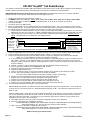
INSTALLATION
MANUAL
IMPORTANT NOTICE: Every effort has been made to assure the accuracy of the information contained in this document as of the
date printed. The extent of integration between the Elk Products M1XSP and other products varies from product to product. Some
integration is more powerful or feature rich than others. In some cases there are variables or limitations not within Elk's control
which may render certain desirable features unavailable or unusable. Certain manufacturer products and/or protocols, including
Elk's may not contain the capabilities or data definitions to permit additional integration beyond what is currently available. In
addition, manufacturers may add, modify, or discontinued features or support with little or no notification to others. For reasons
stated, Elk Products makes no warranty that it will be able to integrate all available features or operations, nor does it make any
express or implied warranties of fitness for a particular purpose or of merchantability. Refer to Elk's Limited Warranty.
M1XSP Rev. F 3/20/07
PO Box 100
3266 US Hwy 70 West
Hildebran, NC 28637
828-397-4200 828-397-4415 Fax
http://www.elkproducts.com
Printed in USA
Table of Contents
General Installation and Setup ..................................................................................................... 3
Updating/Replacing Firmware in the ELK-M1XSP .................................................................................... 4
Aprilaire 8870 Thermostat(s)......................................................................................................... 5
RCS TR16 (RS-232 Format) Thermostat(s) ................................................................................. 6
RCS TR16/TR40 (RS-485 Format) Thermostats(s) ...................................................................... 7
HAI RC Series (RS-232 Format) Thermostat(s) ........................................................................... 8
Lighting Controllers with RS-232 "Serial" Interfaces ................................................................. 9
OnQ-ALC - (Individual Lighting Switches) .................................................................................. 10
UPB - (Individual Lighting Loads and Links) .............................................................................. 12
Centralite LiteJet - (Individual Lighting Loads and Scenes) ....................................................... 14
Lutron RadioRA - (Phantoms, Zones, Security Flash/Solid, Master Ctrl Buttons) ........................ 16
Insteon - (Individual Lighting Loads and Scenes) ....................................................................... 18
UPLINK "AnyNET" Cell Radio Backup ..................................................................................... 22
W800RF32 X-10 RF Receiver from WGL Associates ................................................................ 23
Data Bus E.O.L. Termination - VERY IMPORTANT! ................................................................... 24
M1XSP Compatibility, Jumper Settings and Misc. Information ................................................ 26
APPLICATION:
The ELK-M1XSP is a "3 in 1" product. As a lighting interface, it adapts the M1 Control to many brands of Lighting control
products which use “serial" communications. i.e.,OnQ-ALC, PCS-UPB, EDT, CENTRALITE, etc. As a thermostat
interface, it adapts the M1 Control to HVAC Communicating Thermostats from companies such as:RCS, APRILAIRE,
and HAI. As a serial port expander, it expands the RS-232 communication ports of the M1 for multiple connections
to most any type of equipment that communicates using serial ASCII commands. i.e., Personal Computers and many
types of equipment which feature an RS-232 communications connection. Jumpers on the M1XSP select the
appropriate application, connection, and protocol. Best of all, the M1XSP operates from the 4-wire (RS-485) M1 Keypad
data bus, allowing RS-232 ports to be located long distances from the control. The M1G (Gold) and M1EZ8 Cross
Platform Controls support up to 7 M1XSPs. The communications baud rate is adjustable from 300 to 38,400 baud.
The unit comes complete with cable and a black surface mountable housing.
FEATURES:
• Adapts the M1 and M1EZ8 to specific Lighting control products which use "serial" communications.
• Adapts the M1 and M1EZ8 to specific HVAC Communicating Thermostats from RCS, Aprilaire, and HAI
• Expands the M1 and M1EZ8 RS-232 Serial Ports
• Connect to and Operates from the RS485 Data Bus
• Address Settings via DIP Switches
• Jumper Options and LED Diagnostic indicator
• On-Board EOL Bus Termination Jumper
• Flash Memory for Firmware Updating
SPECIFICATIONS:
• Maximum of Expandable Ports (Units): 7 with M1G or M1EZ8
• Operating Voltage: 12 Volts D.C.
• Current Draw: 31mA
• Housing Dimensions: 4.375" x 3.0" x 1.125"
• Circuit Board Dimensions: 3.5" x 2.75
Page 2
M1XSP Installation Manual
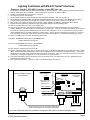
General Installation and Setup
INSTALL UNIT * SET ADDRESS AND OPTION JUMPERS * ACTIVATE M1 BUS ENROLLMENT PROCESS
J1 -Factory
Use ONLY!
JP3 - Jumper selects
between RS-232 or
RS-485
Jumpers
S1,S2,S3 select
BAUD rate
JP1 - Jumper selects
termination of M1
RS-485 Data Bus
JP2 - Jumper selects
termination of
other Mfg. RS-485
Jumpers
S4,S5,S6,S7,S8
select Interface
MODE
Data Bus
Address
Switches
"DB9" 9 Pin
RS-232
Connection to
other Mfg.
RS-485
Connection
to other Mfg.
RS-485
M1 Data Bus
Connection
JP5 - Jumper Selects
+12VDC to DB9 Pin 2
(MUST be in-place for
HAI Thermostats)
1.
The M1XSP operates on the M1's Keypad data bus and may be remotely located near the equipment to which it is
interfacing. Two (2) #6 x 1/2" screws (not provided), one on each side of the black box should be used. It can also be
mounted inside the M1 cabinet using the same method OR by removing the board from the black box and installing the
board into a pair of ELK-SWG Plastic Glide brackets.
2.
Before making any wiring connections, turn Off the M1 Master Power Switch.
3.
Connect terminals +12V, A, B, and Neg from the M1XSP to the M1's Keypad Data Bus (terminals +VKP, Data A, Data B, &
Neg). NOTE: Refer to the M1 Installation Manual and the M1DBH information in this manual about proper
connections of data bus devices with multiple homerun cables.
4.
There are 4 address switches, each with a position of OFF or ON (binary value 0 or 1) and a decimal equivalent value of
(1, 2, 4, or 8). The total decimal value of the "ON" switches equates to the data bus address. As a rule, the first M1XSP
should be set to address 1. If more than 1 M1XSP is installed, set each one to a unique (sequential) address (2, 3, etc).
Table 1: Data Bus Address Switches
Data Bus
Address
1
2
3
4
5
6
7
Switch Settings
S1 S2 S3 S4
On Off Off Off
Off On Off Off
On On Off Off
Off Off On Off
On Off On Off
Off On On Off
On On On Off
Other Jumper Settings
JP1 Used to engage a 120 Ohm resistor
for terminating the M1 RS-485 Data BuS.
See Data bus wiring instructions before use.
IMPORTANT: When interfacing with HAI Thermostats, address switches on the M1XSP may ONLY be set to 1, 2, 3, or 4. Address
1 talks with HAI Thermostats addressed as 1 thru 4. Address 2 talks with HAI Thermostats addressed as 5 to 8. Address
3 talks with HAI Thermostats addressed as 9 to 12. Address 4 talks with HAI Thermostats addressed as 13 to 16.
5.
Set the Mode jumpers according to the desired application. Refer to the jumper settings table on page 10. If the M1XSP
is being used for a Lighting or Thermostat application the baud rate will be internally fixed according to the mode/protocol.
The baud rate jumpers are ignored UNLESS it is jumpered to be a Serial Port Expander.
M1XSP Installation Manual
Page 3
Steps 6 & 7 may be skipped when using the M1XSP as a Lighting or Themostat interface.
6.
If the M1XSP is only being used as a serial port expander, it will necessary to set the BAUD Rate Jumpers to the desired
speed. Refer to the back page of these instructions.
7.
As a serial port expander, the M1XSP can be connected to a PC or other communication equipment using a standard 9
pin RS-232 serial cable. Distance for an RS-232 serial cable is 10 ft. nominal, 50 ft. maximum. Of course, since the
M1XSP operates on the M1's 4-wire Keypad Data Bus, it can be located a great distance from the M1 and thereby closer to
the other equipment so that the RS-232 length limits are not such an issue.
8.
For use with Thermostats or Lighting Controllers, set the Format jumper (JP3) according to the type of communication
format that the interfacing equipment requires. In 99% of the cases this jumper will probably be set to the "232" position.
Refer to the the jumper settings on page 10.
9.
For Thermostat and Lighting Controller hookups refer to the appropriate diagrams on the following pages.
10. After all connections are complete, turn On the M1 Master Power Switch.
11. Enroll the M1XSP into the M1 Control as follows: From the Keypad access the Installer level programming. Select Menu
01-Bus Module Enrollment. Press the right arrow key to start the enrollment. When the keypad indicates enrollment
complete, press the right arrow key to view the results. Among the displayed enrolled devices there should be a type 5
(T5) device at address 01.
NOTE: If it becomes necessary to replace an already installed M1XSP, set the new unit to the same address as the old
unit and repeat this enrollment process. If a device is permanently removed, the enrollment process must be performed
in order to de-enroll the unit and thereby prevent a "missing" trouble condition.
Diagnostic LED indication
Slow blink (1/2 sec.) = Normal communication with M1.
Fast flicker = Communicating with other equipment (Thermostat, Lighting Controller, PC, etc.)
No blink = No communication with M1. Unit might be unplugged or powered off.
IMPORTANT:
The number of manufacturer supported "out-of-the-box" interfaces are limited by the internal memory of the M1XSP. Some
interfaces require a lot of memory. Fortunately, due to the M1XSPs Flash Memory, this limitation can be averted with different
'Field Installable firmware "volumes", each containing specific manufacturer interfaces. For example: to take an "off-the-shelf"
M1XSP and use it for Insteon lighting you will need to download and flash the memory with firmware 50.x.x. For reference the
current Factory shipped firmware and the alternate Field Installable firmware versions and numbering protocol are as follows:
1.x.x Factory "Out-of-the-box" Firmware: (Aprilaire,RCS,HAI,OnQ-ALC,UPB,Centralite,EDT,Dynalite,LutronRA,W800RF32)
25.x.x Field Installable Firmware for an Elk-M1XZW Z-Wave Module. (Used only in the M1XZW which is a subset of the M1XSP)
50.x.x Field Installable Firmware specific to Insteon.
NOTE: The first digit (1,25,50,etc) is the volume identifier. The second and third digits identify the revision levels.
Updating/Replacing Firmware in the ELK-M1XSP
The M1XSP stores it’s operating firmware in “Flash” memory. This state-of-the-art memory allows electronic field updates
and eliminates the old fashion method of changing IC chips or shipping boards back to the factory. As new firmware updates
become available, they will be posted on ELK’s Dealer ONLY restricted website found at www.elkproducts.com. NOTE:
Firmware updating can only be done through the M1 Control using a Direct to PC Com port connection or an optional
Ethernet Network connection. Dial-up connections cannot be used to perform firmware updates.
How to Update Firmware:
1. Physically connect the Computer and Control using either the RS-232 Serial Ports or the M1XEP Ethernet Interface.
3. Start ElkRP and open the account belonging to the control. Click on the Connection menu icon and establish a connection. Again, use the appropriate Direct using Com_ OR Network options.
4. Click on Update/Verify Firmware from the Send/Rcv menu icon.
5. On the Update/Verify screen, select the device to be updated. In this case it is a Serial Expander. Then also select the
“Update to new firmware” option. Then click Continue.
6. The Update Firmware screen displays the device name, the current Firmware, Hardware, and Bootware version, and a
pull down window for selecting the firmware version to use on the update. Select the appropriate firmware that you wish to
use. NOTE: All update (.bin) files that are downloaded or received should be stored in your ~Program
Files\ElkRP\Updates directory. This is where RP looks for all update files.
7. Click on the check box for “Update”. If “Reprogram” or “Rollback” is displayed the firmware file is the same as OR older
that what is in the control. Reprogramming with the same firmware is a waste of time but was included for factory testing
purposes. Rollback is not recommended except under the guidance of Elk Technical Support.
Page 4
M1XSP Installation Manual
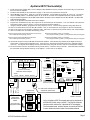
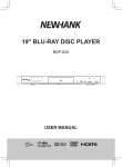
Aprilaire 8870 Thermostat(s)
1.
Install and wire the Aprilaire 8811 Protocol Adapter, 8818 Distribution Panel, and 8870 Thermostat using the instructions
that come with the Aprilaire.
2. Install the ELK-M1XSP per the instructions on page 3. Be sure to enroll the device into the M1.
3. Set the MODE jumpers S5=1, S6=0, S7=1, & S8=1 for Aprilaire. If the M1XSP has a jumper S4, set it to =1. Set Jumper
JP3 to the "232" position. The BAUD jumpers S1,S2, & S3 do not matter as the Aprilaire baud rate is preset internally.
4. Plug the Aprilaire supplied 6 ft RJ to DB9 Cable between the 8811 Protocol Adapter and the ELK-M1XSP. DO NOT USE
THE ELK-WO37A CABLE.
5. Power up the Aprilaire Thermostat and Protocol Adapter.
6. Program the unit address and any other options in the Thermostat per its instructions. The unit address must match the
Thermostat number in the M1 Control. The first Thermostat should be Address 1.
7. Using the ELK-RP Software, program the M1 using steps A,B, and C. Test and verify operation using steps D and E.
7a. Click on the Automation Tab in the ELK-RP software. Click on Thermostat icon and program a name for Thermostat 1.
7b. Click on the Task icon and program at least two tasks. Name the 1st Task "Economy Mode" and the 2nd "Comfort Mode".
7c. Click on the Rules icon and create the following 4 rules.
Whenever [Area Name] Armed State Becomes Armed Away
Then Activate [Economy Mode] (Task 1)
Whenever [Task Name] (Task 1) Is Activated
Then Set [Thermostat 1] (TStat 1) Cooling Desired Temp to 85 degrees
Whenever [Area] Armed State Becomes Disarmed
Then Activate [Comfort Mode] (Task 2)
Whenever [Task Name] (Task 2) Is Activated
Then Set [Thermostat 1] (TStat 1) Cooling Desired Temp to 70 degrees
7d. Use the M1 Keypad to verify the M1XSP & Thermostat operation. Press the ELK key followed by the Right arrow key to
access Menu 1-View/Control Automation Fncts. Press 6 for the Thermostat Temperature sub-menu, followed by Right
arrow key. The Keypad should display the first Thermostat (T01) along with its name and current temperature reading.
7e. Go into the Tasks sub-menu and select Economy Mode (Task 1). Press the # key to activate. When this task is activated
the thermostat cooling setpoint should go to 85 degrees. Confirm this on the display.
MODE
For Aprilaire
set to 1011 **
LEDs
POWER
RX TX RX TX
DATA ENABLE
RS-485 RS-485
RX TX
DATA
RS-232
1
0
Place plug on top
pins for a 1, on
bottom for a 0.
RS-485
RD/WT
BL/WT
BK/WT
OR/WT
A
B
BAUD
ELK-M1XSP
Interface
S5 S6 S7 S8
MODE
1
0
JP3
JP1
232 485
ON
JP2
Address
RS-232
Switch 1 shown in ON
position (Address 1).
Switches 2,4,8 are Off.
1
2
3
4 +12V A B Neg
JP5
RS-485
Not Used
6 ft. Cable with RJ and DB9 connector
shipped with Aprilaire 8811.
+VKP A B Neg
HVAC
SYSTEM
M1XSP Installation Manual
ADDRESS
C
HVAC
SYSTEM
One required per
eight (8) thermostats
No changes
needed.
RS-232
Aprilaire 8870
THERMOSTATS
Aprilaire 8818
DISTRIBUTION
PANEL
S1 S2 S3
1248
BAUD
RS-485
Jumper JP3
must be in 232
position.
S5 S6 S7 S8
Aprilaire
Electronic Thermostat
Model 8811 Protocol Adapter
Power
7.5VAC
** Early production units do not have the S5 Jumper
To M1 Control
Data Bus Terminals
Up to 16 Aprilaire 8870 Thermostats total can be interfaced to
an ELK-M1G (Gold) using 1 M1XSP. The ELK-M1 (Std) can
interface with a maximum of 2 Aprilaire 8870 Thermostats.
The thermostat brand, interface format, and model of ELK-M1
Control dictates the total number of thermostats allowed.
Page 5
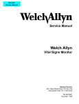
RCS TR16 (RS-232 Format) Thermostat(s)
1.
2.
3.
Install, and wire the RCS Control Unit and Wall Display Unit to the HVAC system per the RCS instructions.
Install the ELK-M1XSP per the instructions on page 3. Be sure to enroll the device into the M1.
Set the MODE jumpers S5=1, S6=0, S7=0, & S8=1 for RCS mode. If the M1XSP has jumper S4, set it to =1. Set Jumper
JP3 to the "232" position. The BAUD jumpers S1,S2, & S3 do not matter as the RCS baud rate is preset internally.
4. Connect the Black, Red, and Green wires from the ELK-WO37A cable to the RS-232 terminals on the RCS Thermostat
Control unit. The White (Yellow) wire is optional. It may be used to supply +12VDC from the M1XSP to the Thermostat in
lieu of the HVAC power. Consult the RCS manual for details. Plug the other end of the ELK-WO37A cable into the 9 pin
serial connector on the M1XSP.
5. Power up the RCS Thermostat Control Unit.
6. Program the Unit Address and any other options in the RCS Unit per its instructions. The unit address must match the
Thermostat number in the M1 Control. The first Thermostat should be Address 1.
7. Using the ELK-RP Software, program the M1 using the following steps. Test and verify operation using steps d and e.
7a. Click on the Automation Tab in the ELK-RP software. Click on Thermostat icon and program a name for Thermostat 1.
7b. Click on the Task icon and program at least two tasks. Name the 1st Task "Economy Mode" and the 2nd "Comfort Mode".
7c. Click on the Rules icon and create the following 4 rules.
Whenever [Area Name] Armed State Becomes Armed Away
Then Activate [Economy Mode] (Task 1)
Whenever [Task Name] (Task 1) Is Activated
Then Set [Thermostat 1] (TStat 1) Cooling Desired Temp to 85 degrees
Whenever [Area] Armed State Becomes Disarmed
Then Activate [Comfort Mode] (Task 2)
Whenever [Task Name] (Task 2) Is Activated
Then Set [Thermostat 1] (TStat 1) Cooling Desired Temp to 70 degrees
7d. Use the M1 Keypad to verify the M1XSP & Thermostat operation. Press the ELK key followed by the Right arrow key to
access Menu 1-View/Control Automation Fncts. Press 6 for the Thermostat Temperature sub-menu, followed by Right
arrow key. The Keypad should display the first Thermostat (T01) along with its name and current temperature reading.
7e. Go into the Tasks sub-menu and select Economy Mode (Task 1). Press the # key to activate. When this task is activated
the thermostat cooling setpoint should go to 85 degrees. Confirm this on the Thermostat display.
TS16
Wall Display
Unit
WDU
GND
+12VDC
+12VDC
CLOCK
CLOCK
DATA
DATA
RED
GREEN
12V
GND
D+
D-
** Early production units do not have the S5 Jumper
Jumper JP3
must be in 232
position.
S5 S6 S7 S8
HVAC SYSTEM
GND
WHT (YEL)
BLACK
MODE
For RCS
set to 1001 **
RCS TR16
"RS-232"
Control Unit
1
0
S1 S2 S3
1
0
BAUD
ON
Connection of White (Yel) wire is optional. It can
be used to supply +12VDC from the M1XSP to the
thermostat control unit in lieu of the HVAC power.
If not used, tape or insulate the White (Yel) wire.
S5 S6 S7 S8
MODE
No changes
needed.
JP3
JP1
232 485
1248
ADDRESS
RS-232
BAUD
Place plug on top
pins for a 1, on
bottom for a 0.
ELK-M1XSP
Interface
JP2
Address
RS-232
Switch 1 shown in ON
position (Address 1).
Switches 2,4,8 are Off.
1
2
3
4 +12V A B Neg
JP5
RS-485
Not Used
+VKP A B Neg
Part # WO37A - 10 ft. Cable with 4 flying leads and
DB9 connector (shipped with ELK-M1XTI)
To M1 Control
Data Bus Terminals
Up to 7 RCS TR16 Thermostats (RS-232 format) can be interfaced to an ELK-M1G (Gold). The ELK-M1 (Std) can
interface to 1 thermostat. In the RS-232 format, each RCS thermostat requires a separate ELK-M1XSP Interface.
However, in the RS-485 format, up to 16 RCS TR16/TR40 Thermostats can be connected to an ELK-M1G (Gold).
The ELK-M1 (Std) is still limited to 1 thermostat. See RCS 485 diagram on opposite page. The thermostat brand,
interface format, and model of the ELK-M1 Control all determine the total number of thermostats allowed.
Page 6
M1XSP Installation Manual
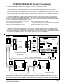
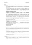
RCS TR16/TR40 (RS-485 Format) Thermostats(s)
1.
2.
3.
Install, and wire the RCS Control Unit and Wall Display Unit to the HVAC system per the RCS instructions.
Install the ELK-M1XSP per the instructions on page 3. Be sure to enroll the device into the M1.
Set the MODE jumpers S5=1, S6=0, S7=0, & S8=1 for RCS mode. If the M1XSP has jumper S4, set it to =1. Set Jumper
JP3 to the "485" position. The BAUD jumpers S1,S2, & S3 do not matter as the RCS baud rate is preset internally.
4. Using a 3 conductor cable and the diagram below, connect the GND, D+, and D- wires from the RS-485 terminals on the
RCS Thermostat Control unit to the RS-485 terminals on the M1XSP. The supplied WO37A cable (RS-232) is not used.
5. Power up the RCS Thermostat Control Unit.
6. Program the Unit Address and any other options in the RCS Unit per its instructions. The unit address must match the
Thermostat number in the M1 Control. The first Thermostat should be Address 1.
7. Using the ELK-RP Software, program the M1 using the following steps. Test and verify operation using steps d and e.
7a. Click on the Automation Tab in the ELK-RP software. Click on Thermostat icon and program a name for Thermostat 1.
7b. Click on the Task icon and program at least two tasks. Name the 1st Task "Economy Mode" and the 2nd "Comfort Mode".
7c. Click on the Rules icon and create the following 4 rules.
Whenever [Area Name] Armed State Becomes Armed Away
Then Activate [Economy Mode] (Task 1)
Whenever [Task Name] (Task 1) Is Activated
Then Set [Thermostat 1] (TStat 1) Cooling Desired Temp to 85 degrees
Whenever [Area] Armed State Becomes Disarmed
Then Activate [Comfort Mode] (Task 2)
Whenever [Task Name] (Task 2) Is Activated
Then Set [Thermostat 1] (TStat 1) Cooling Desired Temp to 70 degrees
7d. Use the M1 Keypad to verify the M1XSP & Thermostat operation. Press the ELK key followed by the Right arrow key to
access Menu 1-View/Control Automation Fncts. Press 6 for the Thermostat Temperature sub-menu, followed by Right
arrow key. The Keypad should display the first Thermostat (T01) along with its name and current temperature reading.
7e. Go into the Tasks sub-menu and select Economy Mode (Task 1). Press the # key to activate. When this task is activated
the thermostat cooling setpoint should go to 85 degrees. Confirm this on the thermostat display.
+12VDC
+12VDC
CLOCK
CLOCK
DATA
DATA
RED
BLACK
12V
GREEN
D+
WHITE
D-
GND
HVAC SYSTEM
GND
TSTAT #1
RCS TR16/TR40
"RS-485"
Control Unit
RS-485
0
S1 S2 S3
BAUD
Place plug on top
pins for a 1, on
bottom for a 0.
1
0
BAUD
ON
MODE
No changes
needed.
JP3
JP1
232 485
1248
JP2
Address
RS-232
ADDRESS
RCS TR16/TR40 Thermostat
(RS-485 format)
S5 S6 S7 S8
Switch 1 shown in ON
position (Address 1).
Switches 2,4,8 are Off.
RS-485
1
RS-232
Not Used
2
3
4 +12V A B Neg
22 awg. - 3 conductors (Max. length 1500 ft.)
Wall
Display Unit
+VKP A B Neg
To M1 Data Bus
Connections
Wall
Display Unit
RCS TR16/TR40
"RS-485"
Control Unit
TSTAT #3
RED
BLACK
GREEN
WHITE
12V
GND
D+
D-
RCS TR16/TR40
"RS-485"
Control Unit
HVAC SYSTEM
12V
GND
D+
D-
HVAC SYSTEM
TSTAT #2
RED
BLACK
GREEN
WHITE
JP5
BLACK
WDU
GND
** Early production units do not have the S5 Jumper
MODE
For RCS
Jumper JP3
ELK-M1XSP
set to 1001 **
must be in 485
S5 S6 S7 S8
Interface
position.
1
GREEN
WHITE
TS?
Wall Display
Unit
To additional Thermostats
Control Units
Using the RS-485 format, up to 16 RCS TR16/TR40 Thermostats total can be interfaced to an ELK-M1G (Gold) using 1
M1XSP. Each thermostat must have a unique address from 1 to 16. The ELK-M1 (Std) is limited to 2 thermostats total.
The brand of thermostat, interface format, and model of ELK-M1 Control dictates the total number of thermostats allowed.
M1XSP Installation Manual
Page 7
HAI RC Series (RS-232 Format) Thermostat(s)
1.
2.
3.
4.
5.
Install, and wire the HAI Thermostat to the HVAC system per the instructions that came with the thermostat.
Install the ELK-M1XSP as per instructions on page 3. Enroll the device into the M1 after setting the data bus address
switches. IMPORTANT: Refer to wiring diagram below and the note regarding which data bus addresses to use.
Set the MODE jumpers S5=1, S6=0, S7=1, & S8=0 for HAI mode. If the M1XSP has jumper S4, set it to =1. Set Jumper
JP3 to the "232" position. The BAUD jumpers S1,S2, & S3 do not matter as the HAI baud rate is preset internally.
Using a four wire cable and some splice connectors, connect the WO37A cable which is supplied with the ELK-M1XSP to
the Black, Red, Green, and Yellow wires of the four pin flying lead cable that is supplied with the HAI Thermostat. Plug the
WO37A cable into the 9 pin serial connector on the M1XSP, then plug the four pin cable into the HAI Thermostat.
Power up the HAI Thermostat, enter the Installer Setup Mode (see page 10 of the HAI manual), and program the following:
A. Set Item #00 "Address" to a value from 1 to 16. The first unit should be address 1. If multiple thermostats are
installed, each should be set to a consecutive address, starting at 1.
B. Set Item #01 "Communications Mode" to a value of 0 (300 baud, RS-232 mode).
C. Set Item #03 "Display Options" to one of the options designated as "non-programmable" (4 thru 7). This disables
the thermostat's internal setback time schedules so they do not override the M1 Automation commands from the M1XSP.
An alternate method is to disable specific schedules by setting their times values to "----" (1 step past the 11:45pm time set).
D. Set Items #05 & #06 "Cool Setpoint Limit" and "Heat Setpoint Limit" (if desired). CAUTION: The thermostat will
ignore any setpoint commands sent to it that are outside these limits.
6. Using the ELK-RP Software, program steps A,B, and C. Test and verify operation using steps D and E.
6a. Click on the Automation Tab in the ELK-RP software. Click on Thermostat icon and program a name for Thermostat 1.
6b. Click on the Task icon and program at least two tasks. Name the 1st Task "Economy Mode" and the 2nd "Comfort Mode".
6c. Click on the Rules icon and create the following 4 rules.
Whenever [Area Name] Armed State Becomes Armed Away
Then Activate [Economy Mode] (Task 1)
Whenever [Task Name] (Task 1) Is Activated
Then Set [Thermostat 1] (TStat 1) Cooling Desired Temp to 85 degrees
Whenever [Area] Armed State Becomes Disarmed
Then Activate [Comfort Mode] (Task 2)
Whenever [Task Name] (Task 2) Is Activated
Then Set [Thermostat 1] (TStat 1) Cooling Desired Temp to 70 degrees
6d. Use the M1 Keypad to verify the M1XSP & Thermostat operation. Press the ELK key followed by the Right arrow key to
access Menu 1-View/Control Automation Fncts. Press 6 for the Thermostat Temperature sub-menu, followed by Right
arrow key. The Keypad should display the first Thermostat (T01) along with its name and current temperature reading.
6e. Go into the Tasks sub-menu and select Economy Mode (Task 1). Press the # key to activate. When this task is activated
the thermostat cooling setpoint should go to 85 degrees. Confirm this on the display.
HVAC SYSTEM
** Early production units will not have the S5 and/or S4 Jumpers
MODE
For HAI
Jumper JP3
ELK-M1XSP
set to 1010 **
must be in 232
S5 S6 S7 S8
Interface
position.
Hold Prog Mode Fan
<
>
1
0
HAI
BLACK
RED
GREEN
YELLOW
BAUD
S5 S6 S7 S8
MODE
1
0
BAUD
This wiring header plugs into the
4 pin jack marked "COMM" on
the back of the HAI Omnistat.
ADDRESS
JP1
JP2
ON
No changes
needed.
JP3
232 485
1248
OMNISTAT
TSTAT #1
Supplied with
HAI Omnistat
S1 S2 S3
Place plug on top
pins for a 1, on
bottom for a 0.
Address
RS-232
Switch 1 shown in ON
position (Address 1).
Switches 2,4,8 are Off.
Only Address 1,2,3, or 4
will work with HAI Tstats
1
2
3
4 +12V A B Neg
JP5
RS-485
Not Used
Part # WO36A - 10 ft. Cable with DB9 connector and
4 flying leads (shipped with ELK-M1XTI)
+VKP A B Neg
To M1 Control Data
Bus Terminals
TSTAT #2
TSTAT #3
TSTAT #4
Place plug on
these two pins
for HAI Omnistats.
The max. number of HAI Tstats that may be connected to a single M1XSP is four (4). Max. wire distance = 500 ft. Each Tstat
must be assigned a unique address from 1 to 4. IMPORTANT: HAI Tstat addresses 1 to 4 MUST be connected to an
M1XSP that is set to data bus address 1. HAI Tstat addresses 5 to 8 MUST be connected to an M1XSP that is set to data
bus address 2. HAI Tstat addresses 9 to 12 MUST be connected to an M1XSP that is set to data bus address 3. HAI
Tstat addresses 13 to 16 MUST be connected to an M1XSP that is set to data bus address 4.
Page 8
M1XSP Installation Manual
Lighting Controllers with RS-232 "Serial" Interfaces
Examples: OnQ-ALC, PCS-UPB, Centralite, Lutron, EDT-iLine, etc.
1.
Install Lighting Controller using the instructions provided by the manufacturer. If the Lighting Controller's interface has an
address setting then set it to address 1. Most controllers do not require an address setting.
3. Install the ELK-M1XSP per the instructions on page 3.
4. Set Jumper JP3 to the "232" position.
5. Set the MODE jumpers to match the particular brand of lighting controller. See chart on page 10.
6. Set the BAUD rate jumpers to 000. (The M1XSP automatically sets the baud rate based on the MODE Jumper setting)
7. Connect a 9-pin serial cable from the Lighting Controller's serial port to the 9 pin connector on the M1XSP.
8. Apply power to the Lighting Controller and the M1XSP. DON'T FORGET TO ENROLL THE M1XSP INTO THE M1.
9. Program and test at least one light device using the ELK-RP Software and the following steps:
9a. Click on the Automation icon, then on the Lighting icon.
9b. Click on Lighting Device 1 and program the Name (1 to 16 characters), Format (manufacturer), and Type (switch,
dimmer, appliance). The "Show" box may be left blank or checked ("X"). If this box is checked, the light will be included in
the scroll list of the Keypad and Telephone remote View/Control Automation menus. If not selected for "Show" the light
will be available ONLY by manually entering the 3 digit number. Click on the Voice Description to program a 1 to 6 word
voice description for this light. Right click on Light 1 and select "Send Lighting 1" to send this programming to the M1.
9c. Click on the Rules icon and create the following 2 test rules.
Test Rule 1: WHENEVER 'Name' (Area 1) IS ARMED AWAY
THEN TURN 'Name' [1 [A1]] ON
Test Rule 2: WHENEVER 'Name' (Area 1) IS DISARMED
THEN TURN 'Name' [1 [A1]] OFF
9d. Click "Send" to transmit these rules to the M1.
9e. Test the manual activation of this light by pressing the ELK key on the M1 Keypad followed by the Right arrow key to select
"Menu 1-View/Control Automation Fncts. Press 2 for the Lighting submenu, followed by the Right arrow key. The keypad
will display the first Light name and number along with its On or Off status. Note: The status will not be correct if the M1 is
powered off. To change the light from On to Off or from Off to On, press the # key.
9f. Test the two automation rules by arming the control to the Away mode. The light should come On. Disarming the M1
should cause the light to turn Off.
10. This confirms the operation. Continue to add or test additional lights as required.
Lighting Controller Interface
or Circuit Board
MODE JUMPERS
Select according to the
table on Page 10. **
** Early production units do not have the S5 Jumper.
Jumper JP3
must be in 232
position.
S5 S6 S7 S8
1
0
Place plug on top
pins for a 1, on
bottom for a 0.
S1 S2 S3
S5 S6 S7 S8
BAUD
MODE
BAUD JUMPERS
No changes needed.
ADDRESS SWITCHES
JP3
1
0
JP1
232
485
1248
RS-232
ELK-M1XSP
Interface
ON
JP2
Address
RS-232
Switch 1 shown in ON
position (Address 1).
Switches 2,4,8 are Off.
1
2
3
4
+12V A B
Neg
JP5
RS-485
Not Used
+VKP A B Neg
Standard Computer type 9 Pin Serial Cable (Male/Female)
NOTE: Some manufacturers may supply a special cable.
To M1 Control
Data Bus Terminals
Consult the Lighting Manufacturer's Installation or Application Manual(s) for complete installation details.
M1XSP Installation Manual
Page 9
OnQ-ALC - (Individual Lighting Switches)
OnQ ALC is a low voltage "wired" lighting technology utilizing a central ALC Master Controller Interface communicating to light
switches and scene switches over a RS-485 proprietary network. An OnQ ALC Serial interface is required for interfacing the
Master Controller Interface with the ELK-M1XSP, and then into the M1 line of controls. The M1XSP supports 31 ALC modules
(dimmers, switches on each of 4 branches for a total of 124 individually addressable ALC devices. The M1XSP also supports
ALC 4 button scene switches, provided they are wired and connected on ALC branch 1.
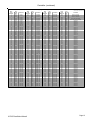
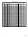
Integration with the M1 is accomplished by "mapping" the ALC addresses and operation to M1 Lighting devices. For example:
ALC devices 1-31 on ALC branch 1 are mapped to M1 Lighting devices 1-31. Additional ALC devices may be added by the
additional of an ALC "branch" expander board in which case..... ALC devices 1-31 on ALC branch 2 are mapped to M1 Lighting
devices 33-63. ALC devices 1-31 on ALC branch 3 are mapped to M1 Lighting devices 65-95. ALC devices 1-31 on ALC branch
4 are mapped to M1 Lighting devices 97-127. M1 Lighting devices 32, 64, 96, and 128 are reserved for activation of the ALC
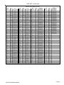
"Virtual Scenes" 1 thru 4 respectively. The chart on the next page shows the M1 Lighting devices and their corresponding ALC
device mapping.
Components required for OnQ ALC integration:
-
An ELK-M1 or ELK-M1EZ8 Controller.
One (1) ELK-M1XSP Serial Port Expander. NOTE: Firmware updates may be downloaded from the ELK M1 Dealer Web site.
One (1) OnQ ALC Master Controller #364644-01 and one (1) ALC Serial Interface #364698-01. ** See NOTE below.
One or more ALC Lighting devices.
Limitations:
The M1XSP can only support ALC 4 button scene switches wired and connected on ALC branch 1.
Setting up the M1XSP and the M1 to communicate with OnQ ALC
1. Install the ELK-M1XSP per the instructions on page 3. Be sure to enroll the device into the M1.
2. Connect the RJ45 modular to 9-pin female serial cable supplied with the OnQ ALC Serial Interface to the male DB9 9 pin
serial connector (J2) on the ELK-M1XSP. The OnQ Lighting Controller is then connected to the OnQ Serial Interface. Note:
An optional expansion module OnQ part #364726-01 is required to obtain the full capacity of 124 Switches.
3. Set the MODE Jumpers on the M1XSP as follows: S4*="1" (UP), S5="1" (UP), S6="1" (UP), S7="0" (DN), S8="0" (DN).
NOTE: Some units do not have jumper S4.
4. Set the M1XSP Jumper JP3="232". The position of BAUD jumpers S1,S2,S3 does not matter.
5. Be sure to set the address switches on the ALC switches and use the OnQ Software to program the features.
6. Power up all the devices.
7. Program the M1 Lighting device attributes utilizing the ElkRP software. Only the specific devices to be used for ALC need to
be programmed. For each individual address program the M1 Lighting device as: "Format=Serial Expander" and "Type=
Dimmer" (Type may also be programmed as "On/Off Switch" if the device isn't dimmable).
When a M1 Light device is activated from a rule or from the M1 Keypad "Automation" menu, the corresponding device command
will be sent from the M1XSP to the ALC Serial Interface. NOTE: Dimming from the Keypad can only be done using a task.
** NOTE: As of the release date of this manual OnQ had announced plans to produce a single module designated the "Elk
Interface". While not yet officially released the OnQ part number is believed to be 364864-01. This new part combines the
OnQ ALC Interface, the ALC Serial Interface, and the ELK-M1XSP, essentially replacing three components with a single
component. More information will be released once this product is available.
Page 10
M1XSP Installation Manual
OnQ-ALC - (continued)
M1 Lighting Devices Mapped to OnQ ALC
ELK
Light
Device #
1
2
3
4
5
6
7
8
9
10
11
12
13
14
15
16
17
18
19
20
21
22
23
24
25
26
27
28
29
30
31
32
33
34
35
36
37
38
39
40
41
42
43
44
45
46
47
48
49
50
51
52
53
54
55
56
57
58
59
60
61
62
63
64
PLC
(X-10)
Ref.
A01
A02
A03
A04
A05
A06
A07
A08
A09
A10
A11
A12
A13
A14
A15
A16
B01
B02
B03
B04
B05
B06
B07
B08
B09
B10
B11
B12
B13
B14
B15
B16
C01
C02
C03
C04
C05
C06
C07
C08
C09
C10
C11
C12
C13
C14
C15
C16
D01
D02
D03
D04
D05
D06
D07
D08
D09
D10
D11
D12
D13
D14
D15
D16
OnQ-ALC
Branch / Switch
B1 Switch 1
B1 Switch 2
B1 Switch 3
B1 Switch 4
B1 Switch 5
B1 Switch 6
B1 Switch 7
B1 Switch 8
B1 Switch 9
B1 Switch 10
B1 Switch 11
B1 Switch 12
B1 Switch 13
B1 Switch 14
B1 Switch 15
B1 Switch 16
B1 Switch 17
B1 Switch 18
B1 Switch 19
B1 Switch 20
B1 Switch 21
B1 Switch 22
B1 Switch 23
B1 Switch 24
B1 Switch 25
B1 Switch 26
B1 Switch 27
B1 Switch 28
B1 Switch 29
B1 Switch 30
B1 Switch 31
Virtual Scene 1
B2 Switch 1
B2 Switch 2
B2 Switch 3
B2 Switch 4
B2 Switch 5
B2 Switch 6
B2 Switch 7
B2 Switch 8
B2 Switch 9
B2 Switch 10
B2 Switch 11
B2 Switch 12
B2 Switch 13
B2 Switch 14
B2 Switch 15
B2 Switch 16
B2 Switch 17
B2 Switch 18
B2 Switch 19
B2 Switch 20
B2 Switch 21
B2 Switch 22
B2 Switch 23
B2 Switch 24
B2 Switch 25
B2 Switch 26
B2 Switch 27
B2 Switch 28
B2 Switch 29
B2 Switch 30
B2 Switch 31
Virtual Scene 2
ELK
Light
Device #
65
66
67
68
69
70
71
72
73
74
75
76
77
78
79
80
81
82
83
84
85
86
87
88
89
90
91
92
93
94
95
96
97
98
99
100
101
102
103
104
105
106
107
108
109
110
111
112
113
114
115
116
117
118
119
120
121
122
123
124
125
126
127
128
M1XSP Installation Manual
PLC
(X-10)
Ref.
E01
E02
E03
E04
E05
E06
E07
E08
E09
E10
E11
E12
E13
E14
E15
E16
F01
F02
F03
F04
F05
F06
F07
F08
F09
F10
F11
F12
F13
F14
F15
F16
G01
G02
G03
G04
G05
G06
G07
G08
G09
G10
G11
G12
G13
G14
G15
G16
H01
H02
H03
H04
H05
H06
H07
H08
H09
H10
H11
H12
H13
H14
H15
H16
OnQ-ALC
Branch / Switch
B3 Switch 1
B3 Switch 2
B3 Switch 3
B3 Switch 4
B3 Switch 5
B3 Switch 6
B3 Switch 7
B3 Switch 8
B3 Switch 9
B3 Switch 10
B3 Switch 11
B3 Switch 12
B3 Switch 13
B3 Switch 14
B3 Switch 15
B3 Switch 16
B3 Switch 17
B3 Switch 18
B3 Switch 19
B3 Switch 20
B3 Switch 21
B3 Switch 22
B3 Switch 23
B3 Switch 24
B3 Switch 25
B3 Switch 26
B3 Switch 27
B3 Switch 28
B3 Switch 29
B3 Switch 30
B3 Switch 31
Virtual Scene 3
B4 Switch 1
B4 Switch 2
B4 Switch 3
B4 Switch 4
B4 Switch 5
B4 Switch 6
B4 Switch 7
B4 Switch 8
B4 Switch 9
B4 Switch 10
B4 Switch 11
B4 Switch 12
B4 Switch 13
B4 Switch 14
B4 Switch 15
B4 Switch 16
B4 Switch 17
B4 Switch 18
B4 Switch 19
B4 Switch 20
B4 Switch 21
B4 Switch 22
B4 Switch 23
B4 Switch 24
B4 Switch 25
B4 Switch 26
B4 Switch 27
B4 Switch 28
B4 Switch 29
B4 Switch 30
B4 Switch 31
Virtual Scene 4
ELK
Light
Device #
129
130
131
132
133
134
135
136
137
138
139
140
141
142
143
144
145
146
147
148
149
150
151
152
153
154
155
156
157
158
159
160
161
162
163
164
165
166
167
168
169
170
171
172
173
174
175
176
177
178
179
180
181
182
183
184
185
186
187
188
189
190
191
192
PLC
(X-10)
Ref.
I01
I02
I03
I04
I05
I06
I07
I08
I09
I10
I11
I12
I13
I14
I15
I16
J01
J02
J03
J04
J05
J06
J07
J08
J09
J10
J11
J12
J13
J14
J15
J16
K01
K02
K03
K04
K05
K06
K07
K08
K09
K10
K11
K12
K13
K14
K15
K16
L01
L02
L03
L04
L05
L06
L07
L08
L09
L10
L11
L12
L13
L14
L15
L16
OnQ-ALC
Branch/Node/SS
Scene Switch
B1/Node1/SS 2
B1/Node1/SS 3
B1/Node1/SS 4
B1/Node2/SS 2
B1/Node2/SS 3
B1/Node2/SS 4
B1/Node3/SS 2
B1/Node3/SS 3
B1/Node3/SS 4
B1/Node4/SS 2
B1/Node4/SS 3
B1/Node4/SS 4
B1/Node5/SS 2
B1/Node5/SS 3
B1/Node5/SS 4
B1/Node6/SS 2
B1/Node6/SS 3
B1/Node6/SS 4
B1/Node7/SS 2
B1/Node7/SS 3
B1/Node7/SS 4
B1/Node8/SS 2
B1/Node8/SS 3
B1/Node8/SS 4
B1/Node9/SS 2
B1/Node9/SS 3
B1/Node9/SS 4
B1/Node10/SS 2
B1/Node10/SS 3
B1/Node10/SS 4
B1/Node11/SS 2
B1/Node11/SS 3
B1/Node11/SS 4
B1/Node12/SS 2
B1/Node12/SS 3
B1/Node12/SS 4
B1/Node13/SS 2
B1/Node13/SS 3
B1/Node13/SS 4
B1/Node14/SS 2
B1/Node14/SS 3
B1/Node14/SS 4
B1/Node15/SS 2
B1/Node15/SS 3
B1/Node15/SS 4
B1/Node16/SS 2
B1/Node16/SS 3
B1/Node16/SS 4
B1/Node17/SS 2
B1/Node17/SS 3
B1/Node17/SS 4
B1/Node18/SS 2
B1/Node18/SS 3
B1/Node18/SS 4
B1/Node19/SS 2
B1/Node19/SS 3
B1/Node19/SS 4
B1/Node20/SS 2
B1/Node20/SS 3
B1/Node20/SS 4
B1/Node21/SS 2
B1/Node21/SS 3
B1/Node21/SS 4
B1/Node22/SS 2
The PLC column is for reference only.
ELK
Light
Device #
193
194
195
196
197
198
199
200
201
202
203
204
205
206
207
208
209
210
211
212
213
214
215
216
217
218
219
220
221
222
223
224
225
226
227
228
229
230
231
232
233
234
235
236
237
238
239
240
241
242
243
244
245
246
247
248
249
250
251
252
253
254
255
256
PLC
(X-10)
Ref.
M01
M02
M03
M04
M05
M06
M07
M08
M09
M10
M11
M12
M13
M14
M15
M16
N01
N02
N03
N04
N05
N06
N07
N08
N09
N10
N11
N12
N13
N14
N15
N16
O01
O02
O03
O04
O05
O06
O07
O08
O09
O10
O11
O12
O13
O14
O15
016
P01
P02
P03
P04
P05
P06
P07
P08
P09
P10
P11
P12
P13
P14
P15
P16
OnQ-ALC
Branch/Node/SS
Scene Switch
B1/Node22/SS 3
B1/Node22/SS 4
B1/Node23/SS 2
B1/Node23/SS 3
B1/Node23/SS 4
B1/Node24/SS 2
B1/Node24/SS 3
B1/Node24/SS 4
B1/Node25/SS 2
B1/Node25/SS 3
B1/Node25/SS 4
B1/Node26/SS 2
B1/Node26/SS 3
B1/Node26/SS 4
B1/Node27/SS 2
B1/Node27/SS 3
B1/Node27/SS 4
B1/Node28/SS 2
B1/Node28/SS 3
B1/Node28/SS 4
B1/Node29/SS 2
B1/Node29/SS 3
B1/Node29/SS 4
B1/Node30/SS 2
B1/Node30/SS 3
B1/Node30/SS 4
B1/Node31/SS 2
B1/Node31/SS 3
B1/Node31/SS 4
Page 11
UPB - (Individual Lighting Loads and Links)
UPB is a form of Powerline Communications "PLC" technology for communicating to light switches and scene switches. A UPB
Communications Interface Module "CIM" is required for interfacing with the ELK-M1XSP, and then into the M1 line of controls.
The M1XSP supports 192 UPB individual addresses (dimmers, switches) and 64 UPB Links (scenes).
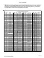
Integration with the M1 is accomplished by "mapping" the UPB addresses and operation to M1 Lighting devices. For example:
UPB individual addresses 1-192 are mapped to M1 Lighting devices 1-192. UPB Links 1-64 are mapped to M1 Lighting devices
193-256. NOTE: Links require M1XSP firmware version 1.0.14 or higher. The chart on the next page shows the M1 Lighting
devices and their corresponding UPB device mapping.
Components required for UPB integration:
-
An ELK-M1 or ELK-M1EZ8 Controller.
One (1) ELK-M1XSP Serial Port Expander. NOTE: Firmware updates may be downloaded from the ELK M1 Dealer Web site.
One (1) UPB Computer Interface Module "CIM".
One or more UPB Lighting devices.
Limitations:
UPB modules will not send their recent status changes in response to link commands. Therefore, the status displayed by the
M1 Controller may not always match the true status of UPB devices if they have been controlled by a Link command.
Setting up the M1XSP and the M1 to communicate with UPB
1. Install the ELK-M1XSP per the instructions on page 3. Be sure to enroll the device into the M1.
2. Connect the female end of the supplied 9-pin serial cable to the M1XSP and the male end to the UPB Computer Interface
Module "CIM".
3. Set the MODE Jumpers on the M1XSP as follows: S4*="1" (UP), S5="1" (UP), S6="1" (UP), S7="0" (DN), S8="1" (UP).
NOTE: Some units do not have jumper S4.
4. Set the M1XSP Jumper JP3="232". Set JP5 to ON. The position of BAUD jumpers S1,S2,S3 does not matter.
5. Power up all the devices.
6. Program the M1 Lighting device attributes utilizing the ElkRP software. Only the specific devices to be used for UPB need to
be programmed. For individual addresses program M1 Lighting devices: 1-192 "Format=Serial Expander" and "Type=
Dimmer" (Type may also be programmed as "On/Off Switch" if the device isn't dimmable). For the link addresses
program M1 Lighting devices: 193-256 as "Format= Serial Expander", "Type=On/Off Switch".
When a M1 Light device is activated from a rule or from the M1 Keypad "Automation" menu, the corresponding device command
will be sent from the M1XSP to the UPB CIM. NOTE: Dimming from the Keypad can only be done using a task.
Programming the UPB devices:
Use the UPB UPStart Software to program the UPB modules with an address, network ID, and any other options. In order to
receive "Load Status" changes from the UPB devices, make sure to program their option bit "Transmit Changes".
VERY IMPORTANT: The same unique UPB NETWORK ID programmed and stored in the UPB
switches must also be programmed into the M1 using the ElkRP software. Refer to the ElkRP
software, "Globals" folder, "G29-G42 Special" tab.
Page 12
M1XSP Installation Manual
UPB - (continued)
M1 Lighting Devices Mapped to UPB
ELK
Light
Device #
1
2
3
4
5
6
7
8
9
10
11
12
13
14
15
16
17
18
19
20
21
22
23
24
25
26
27
28
29
30
31
32
33
34
35
36
37
38
39
40
41
42
43
44
45
46
47
48
49
50
51
52
53
54
55
56
57
58
59
60
61
62
63
64
PLC
(X-10)
Ref.
A01
A02
A03
A04
A05
A06
A07
A08
A09
A10
A11
A12
A13
A14
A15
A16
B01
B02
B03
B04
B05
B06
B07
B08
B09
B10
B11
B12
B13
B14
B15
B16
C01
C02
C03
C04
C05
C06
C07
C08
C09
C10
C11
C12
C13
C14
C15
C16
D01
D02
D03
D04
D05
D06
D07
D08
D09
D10
D11
D12
D13
D14
D15
D16
UPB
Switch 1
Switch 2
Switch 3
Switch 4
Switch 5
Switch 6
Switch 7
Switch 8
Switch 9
Switch 10
Switch 11
Switch 12
Switch 13
Switch 14
Switch 15
Switch 16
Switch 17
Switch 18
Switch 19
Switch 20
Switch 21
Switch 22
Switch 23
Switch 24
Switch 25
Switch 26
Switch 27
Switch 28
Switch 29
Switch 30
Switch 31
Switch 32
Switch 33
Switch 34
Switch 35
Switch 36
Switch 37
Switch 38
Switch 39
Switch 40
Switch 41
Switch 42
Switch 43
Switch 44
Switch 45
Switch 46
Switch 47
Switch 48
Switch 49
Switch 50
Switch 51
Switch 52
Switch 53
Switch 54
Switch 55
Switch 56
Switch 57
Switch 58
Switch 59
Switch 60
Switch 61
Switch 62
Switch 63
Switch 64
ELK
Light
Device #
65
66
67
68
69
70
71
72
73
74
75
76
77
78
79
80
81
82
83
84
85
86
87
88
89
90
91
92
93
94
95
96
97
98
99
100
101
102
103
104
105
106
107
108
109
110
111
112
113
114
115
116
117
118
119
120
121
122
123
124
125
126
127
128
PLC
(X-10)
Ref.
E01
E02
E03
E04
E05
E06
E07
E08
E09
E10
E11
E12
E13
E14
E15
E16
F01
F02
F03
F04
F05
F06
F07
F08
F09
F10
F11
F12
F13
F14
F15
F16
G01
G02
G03
G04
G05
G06
G07
G08
G09
G10
G11
G12
G13
G14
G15
G16
H01
H02
H03
H04
H05
H06
H07
H08
H09
H10
H11
H12
H13
H14
H15
H16
UPB
Switch 65
Switch 66
Switch 67
Switch 68
Switch 69
Switch 70
Switch 71
Switch 72
Switch 73
Switch 74
Switch 75
Switch 76
Switch 77
Switch 78
Switch 79
Switch 80
Switch 81
Switch 82
Switch 83
Switch 84
Switch 85
Switch 86
Switch 87
Switch 88
Switch 89
Switch 90
Switch 91
Switch 92
Switch 93
Switch 94
Switch 95
Switch 96
Switch 97
Switch 98
Switch 99
Switch 100
Switch 101
Switch 102
Switch 103
Switch 104
Switch 105
Switch 106
Switch 107
Switch 108
Switch 109
Switch 110
Switch 111
Switch 112
Switch 113
Switch 114
Switch 115
Switch 116
Switch 117
Switch 118
Switch 119
Load 120
Load 121
Load 122
Load 123
Load 124
Load 125
Load 126
Load 127
Load 128
ELK
Light
Device #
129
130
131
132
133
134
135
136
137
138
139
140
141
142
143
144
145
146
147
148
149
150
151
152
153
154
155
156
157
158
159
160
161
162
163
164
165
166
167
168
169
170
171
172
173
174
175
176
177
178
179
180
181
182
183
184
185
186
187
188
189
190
191
192
PLC
(X-10)
Ref.
I01
I02
I03
I04
I05
I06
I07
I08
I09
I10
I11
I12
I13
I14
I15
I16
J01
J02
J03
J04
J05
J06
J07
J08
J09
J10
J11
J12
J13
J14
J15
J16
K01
K02
K03
K04
K05
K06
K07
K08
K09
K10
K11
K12
K13
K14
K15
K16
L01
L02
L03
L04
L05
L06
L07
L08
L09
L10
L11
L12
L13
L14
L15
L16
UPB
Switch 129
Switch 130
Switch 131
Switch 132
Switch 133
Switch 134
Switch 135
Switch 136
Switch 137
Switch 138
Switch 139
Switch 140
Switch 141
Switch 142
Switch 143
Switch 144
Switch 145
Switch 146
Switch 147
Switch 148
Switch 149
Switch 150
Switch 151
Switch 152
Switch 153
Switch 154
Switch 155
Switch 156
Switch 157
Switch 158
Switch 159
Switch 160
Switch 161
Switch 162
Switch 163
Switch 164
Switch 165
Switch 166
Switch 167
Switch 168
Switch 169
Switch 170
Switch 171
Switch 172
Switch 173
Switch 174
Switch 175
Switch 176
Switch 177
Switch 178
Switch 179
Switch 180
Switch 181
Switch 182
Switch 183
Switch 184
Switch 185
Switch 186
Switch 187
Switch 188
Switch 189
Switch 190
Switch 191
Switch 192
The PLC column is for reference only.
ELK
Light
Device #
193
194
195
196
197
198
199
200
201
202
203
204
205
206
207
208
209
210
211
212
213
214
215
216
217
218
219
220
221
222
223
224
225
226
227
228
229
230
231
232
233
234
235
236
237
238
239
240
241
242
243
244
245
246
247
248
249
250
251
252
253
254
255
256
PLC
(X-10)
Ref.
M01
M02
M03
M04
M05
M06
M07
M08
M09
M10
M11
M12
M13
M14
M15
M16
N01
N02
N03
N04
N05
N06
N07
N08
N09
N10
N11
N12
N13
N14
N15
N16
O01
O02
O03
O04
O05
O06
O07
O08
O09
O10
O11
O12
O13
O14
O15
016
P01
P02
P03
P04
P05
P06
P07
P08
P09
P10
P11
P12
P13
P14
P15
P16
UPB
Link (Scene) 01
Link (Scene) 02
Link (Scene) 03
Link (Scene) 04
Link (Scene) 05
Link (Scene) 06
Link (Scene) 07
Link (Scene) 08
Link (Scene) 09
Link (Scene) 10
Link (Scene) 11
Link (Scene) 12
Link (Scene) 13
Link (Scene) 14
Link (Scene) 15
Link (Scene) 16
Link (Scene) 17
Link (Scene) 18
Link (Scene) 19
Link (Scene) 20
Link (Scene) 21
Link (Scene) 22
Link (Scene) 23
Link (Scene) 24
Link (Scene) 25
Link (Scene) 26
Link (Scene) 27
Link (Scene) 28
Link (Scene) 29
Link (Scene) 30
Link (Scene) 31
Link (Scene) 32
Link (Scene) 33
Link (Scene) 34
Link (Scene) 35
Link (Scene) 36
Link (Scene) 37
Link (Scene) 38
Link (Scene) 39
Link (Scene) 40
Link (Scene) 41
Link (Scene) 42
Link (Scene) 43
Link (Scene) 44
Link (Scene) 45
Link (Scene) 46
Link (Scene) 47
Link (Scene) 48
Link (Scene) 49
Link (Scene) 50
Link (Scene) 51
Link (Scene) 52
Link (Scene) 53
Link (Scene) 54
Link (Scene) 55
Link (Scene) 56
Link (Scene) 57
Link (Scene) 58
Link (Scene) 59
Link (Scene) 60
Link (Scene) 61
Link (Scene) 62
Link (Scene) 63
** Link (Scene) 64 Alarm Flash
** Link (Scene) 64: When this link is activated from the M1, the M1 will automatically send a special "flash" command. All devices
are programmed to respond to Link 64 will immediately begin flashing until the link is de-activated (turned off) from the M1.
M1XSP Installation Manual
Page 13
Centralite LiteJet - (Individual Lighting Loads and Scenes)
Centralite is a low voltage, centrally controlled, whole-house lighting product. The Centralite load center is installed near the
circuit breaker panel. It contains a processor board with an on-board RS232 serial port for interfacing with the ELK-M1XSP, and
then into the M1 line of controls. The M1XSP supports 192 Centralite individual loads (dimmers, relays) and 64 Centralite
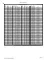
scenes. Integration with the M1 is accomplished by "mapping" the Centalite loads to M1 Lighting devices. For example:
Centralite individual loads 1-192 are mapped to M1 Lighting devices 1-192. Centralite Scenes 1-64 are mapped to M1 Lighting
devices 193-256. The attached chart shows the M1 Lighting devices and their corresponding Centralite Load/Scenes.
Components required for Centralite integration:
-
An ELK-M1 or ELK-M1EZ8 Controller.
One (1) ELK-M1XSP Serial Port Expander. NOTE: Firmware updates may be downloaded from the ELK M1 Dealer Web site.
One (1) Centralite LiteJet System with integrated processor board.
One or more Centralite wall switches.
Limitations:
-
Button presses from a Centralite keypad have no direct integration with the M1. However, it could be possible to assign a
button to a non physical (phantom) load and then use the status change of that load to cause an M1 action.
Load status changes from Centralite to the M1 requires special firmware in both products. See paragraph titled "Load
Status Communications". Even so, in many circumstances it may not be possible for the lighting status displayed by the
M1 Controller to match the true status of the loads.
Setting up the M1XSP and the M1 to communicate with Centralite
1. Install the ELK-M1XSP per the instructions on page 3. Be sure to enroll the device into the M1.
2. Connect the female end of the supplied 9-pin serial cable to the M1XSP and the male end to the 9-pin serial port on the
Centralite processor board marked "RS232-2".
3. Set MODE Jumpers on the M1XSP to a value of 1 1110: S4*="1" (UP), S5="1" (UP), S6="1" (UP), S7="1" (UP), S8="0"
(DN). NOTE: Some units do not have jumper S4.
4. Set the M1XSP Jumper JP3="232". The position of BAUD jumpers S1,S2,S3 does not matter.
5. Power up all the devices.
6. Program the M1 Lighting device attributes utilizing the ElkRP software. Only the specific devices to be used for Centralite
need to be programmed. For individual addresses program M1 Lighting devices: 1-192 "Format=Serial Expander" and
"Type= Dimmer" (Type may also be programmed as "On/Off Switch" if the device isn't dimmable). For the scene
addresses program M1 Lighting devices: 193-256 as "Format= Serial Expander", "Type=On/Off Switch".
When a M1 Light device is activated from a rule or from the M1 Keypad "Automation" menu, the corresponding device command
will be sent from the M1XSP to the Centralite Processor. NOTE: Dimming from the M1 Keypad can only be done using a task.
Load Status Communications:
To receive load status changes from Centralite requires firmware ver 1.0.14 or later in the M1XSP and ver 5.5 or later in the
Centralite LiteJet. Turn ON dipswitch 6 on the LiteJet board but DO NOT program the load "send changes" option.
Note: Version 5.5 or later of the Centralite firmware places a 1 second delay between each load change transmission. This
means that multiple load changes can and will take several seconds to reach the M1. An ALL ON command could take well
over a minute for all loads to report in.
Recap of Centralite Commands supported by M1:
Centralite commands sent by the M1XSP: ^Annn<cr>=Load ON, ^Bnnn<cr>=Load Off, ^Cnnn<cr>=Scene On, Dnnn<cr>=Scene
Off, and ^Ennnllrr<cr>=Load, Level, & Ramp Rate. Where "nnn" represents the load or scene 001-256, "ll" represents the dim
Level 00-99, and "rr" represents the ramp rate 00-31.
Page 14
M1XSP Installation Manual
Centralite - (continued)
M1 Lighting Devices Mapped to Centralite
ELK
Light
Device #
1
2
3
4
5
6
7
8
9
10
11
12
13
14
15
16
17
18
19
20
21
22
23
24
25
26
27
28
29
30
31
32
33
34
35
36
37
38
39
40
41
42
43
44
45
46
47
48
49
50
51
52
53
54
55
56
57
58
59
60
61
62
63
64
PLC
(X-10)
Ref.
A01
A02
A03
A04
A05
A06
A07
A08
A09
A10
A11
A12
A13
A14
A15
A16
B01
B02
B03
B04
B05
B06
B07
B08
B09
B10
B11
B12
B13
B14
B15
B16
C01
C02
C03
C04
C05
C06
C07
C08
C09
C10
C11
C12
C13
C14
C15
C16
D01
D02
D03
D04
D05
D06
D07
D08
D09
D10
D11
D12
D13
D14
D15
D16
Centralite
Load 1
Load 2
Load 3
Load 4
Load 5
Load 6
Load 7
Load 8
Load 9
Load 10
Load 11
Load 12
Load 13
Load 14
Load 15
Load 16
Load 17
Load 18
Load 19
Load 20
Load 21
Load 22
Load 23
Load 24
Load 25
Load 26
Load 27
Load 28
Load 29
Load 30
Load 31
Load 32
Load 33
Load 34
Load 35
Load 36
Load 37
Load 38
Load 39
Load 40
Load 41
Load 42
Load 43
Load 44
Load 45
Load 46
Load 47
Load 48
Load 49
Load 50
Load 51
Load 52
Load 53
Load 54
Load 55
Load 56
Load 57
Load 58
Load 59
Load 60
Load 61
Load 62
Load 63
Load 64
ELK
Light
Device #
65
66
67
68
69
70
71
72
73
74
75
76
77
78
79
80
81
82
83
84
85
86
87
88
89
90
91
92
93
94
95
96
97
98
99
100
101
102
103
104
105
106
107
108
109
110
111
112
113
114
115
116
117
118
119
120
121
122
123
124
125
126
127
128
M1XSP Installation Manual
PLC
(X-10)
Ref.
E01
E02
E03
E04
E05
E06
E07
E08
E09
E10
E11
E12
E13
E14
E15
E16
F01
F02
F03
F04
F05
F06
F07
F08
F09
F10
F11
F12
F13
F14
F15
F16
G01
G02
G03
G04
G05
G06
G07
G08
G09
G10
G11
G12
G13
G14
G15
G16
H01
H02
H03
H04
H05
H06
H07
H08
H09
H10
H11
H12
H13
H14
H15
H16
Centralite
Load 65
Load 66
Load 67
Load 68
Load 69
Load 70
Load 71
Load 72
Load 73
Load 74
Load 75
Load 76
Load 77
Load 78
Load 79
Load 80
Load 81
Load 82
Load 83
Load 84
Load 85
Load 86
Load 87
Load 88
Load 89
Load 90
Load 91
Load 92
Load 93
Load 94
Load 95
Load 96
Load 97
Load 98
Load 99
Load 100
Load 101
Load 102
Load 103
Load 104
Load 105
Load 106
Load 107
Load 108
Load 109
Load 110
Load 111
Load 112
Load 113
Load 114
Load 115
Load 116
Load 117
Load 118
Load 119
Load 120
Load 121
Load 122
Load 123
Load 124
Load 125
Load 126
Load 127
Load 128
ELK
Light
Device #
129
130
131
132
133
134
135
136
137
138
139
140
141
142
143
144
145
146
147
148
149
150
151
152
153
154
155
156
157
158
159
160
161
162
163
164
165
166
167
168
169
170
171
172
173
174
175
176
177
178
179
180
181
182
183
184
185
186
187
188
189
190
191
192
PLC
(X-10)
Ref.
I01
I02
I03
I04
I05
I06
I07
I08
I09
I10
I11
I12
I13
I14
I15
I16
J01
J02
J03
J04
J05
J06
J07
J08
J09
J10
J11
J12
J13
J14
J15
J16
K01
K02
K03
K04
K05
K06
K07
K08
K09
K10
K11
K12
K13
K14
K15
K16
L01
L02
L03
L04
L05
L06
L07
L08
L09
L10
L11
L12
L13
L14
L15
L16
Centralite
Load 129
Load 130
Load 131
Load 132
Load 133
Load 134
Load 135
Load 136
Load 137
Load 138
Load 139
Load 140
Load 141
Load 142
Load 143
Load 144
Load 145
Load 146
Load 147
Load 148
Load 149
Load 150
Load 151
Load 152
Load 153
Load 154
Load 155
Load 156
Load 157
Load 158
Load 159
Load 160
Load 161
Load 162
Load 163
Load 164
Load 165
Load 166
Load 167
Load 168
Load 169
Load 170
Load 171
Load 172
Load 173
Load 174
Load 175
Load 176
Load 177
Load 178
Load 179
Load 180
Load 181
Load 182
Load 183
Load 184
Load 185
Load 186
Load 187
Load 188
Load 189
Load 190
Load 191
Load 192
ELK
Light
Device #
193
194
195
196
197
198
199
200
201
202
203
204
205
206
207
208
209
210
211
212
213
214
215
216
217
218
219
220
221
222
223
224
225
226
227
228
229
230
231
232
233
234
235
236
237
238
239
240
241
242
243
244
245
246
247
248
249
250
251
252
253
254
255
256
PLC
(X-10)
Ref.
M01
M02
M03
M04
M05
M06
M07
M08
M09
M10
M11
M12
M13
M14
M15
M16
N01
N02
N03
N04
N05
N06
N07
N08
N09
N10
N11
N12
N13
N14
N15
N16
O01
O02
O03
O04
O05
O06
O07
O08
O09
O10
O11
O12
O13
O14
O15
016
P01
P02
P03
P04
P05
P06
P07
P08
P09
P10
P11
P12
P13
P14
P15
P16
The PLC column is for reference only.
Centralite
Scene 01 All On
Scene 02 All Off
Scene 03 Vacation
Scene 04 Alarm Flash
Scene 05 Pwr-up Override
Scene 06
Scene 07
Scene 08
Scene 09
Scene 10
Scene 11
Scene 12
Scene 13
Scene 14
Scene 15
Scene 16
Scene 17
Scene 18
Scene 19
Scene 20
Scene 21
Scene 22
Scene 23
Scene 24
Scene 25
Scene 26
Scene 27
Scene 28
Scene 29
Scene 30
Scene 31
Scene 32
Scene 33
Scene 34
Scene 35
Scene 36
Scene 37
Scene 38
Scene 39
Scene 40
Scene 41
Scene 42
Scene 43
Scene 44
Scene 45
Scene 46
Scene 47
Scene 48
Scene 49
Scene 50
Scene 51
Scene 52
Scene 53
Scene 54
Scene 55
Scene 56
Scene 57
Scene 58
Scene 59
Scene 60
Scene 61
Scene 62
Scene 63
Scene 64
Page 15
Lutron RadioRA - (Phantoms, Zones, Security Flash/Solid, Master Ctrl Buttons)
Interfacing to a Lutron RadioRA System requires: ELK-M1XSP Interface with firmware 1.0.14 or greater, 9 pin Serial Cable,
Lutron RA-RS232 Interface, Dimmers, etc.
1. Install the ELK-M1XSP per the instructions on page 3. Be sure to enroll the device into the M1.
2. The M1XSP jumper settings should be: JP3=232 position and JP5=ON, Mode Jumper S4=1 (not all boards have S4 jumper)
S5=0, S6=1,S7=1, and S8=0. BAUD jumpers S1,S2, & S3 do not matter as the Lutron baud rate is preset internally.
3. Plug a standard 9-pin Serial Cable (not included) between the Lutron RA-RS232 DB-9F (female) connector and the
M1XSP DB-9M (male) connector. The ELK-WO37A cable that is supplied with the M1XSP will not be utilized.
4. Follow the instructions in the Lutron RA-RS232 "Setup and Installation Guide". Activate the RS232 interface (pages 8 & 9).
Assign Phantom Buttons as Rooms or Scenes (pages 12 to 25). Assign Zone Numbers if direct control or feedback of an
individual zone (device) is desired (pages 26 to 28). Turn Hardware Handshaking OFF by following the instructions on
pages 33 and 34. Test the Phantom Button On or Off function locally from the RA-RS232 interface (page 42).
5. Use the ELK-RP software to configure the LIGHTING setup for the M1 to control the Lutron Radio RA devices.
Operation with Lutron RadioRA
Operation with Lutron RadioRA is based on "mapped" assignments to M1 Lighting Devices 1 to 256. Commands to Lutron
include: Phantom Button Presses, Direct Zone Control, and Security Mode activation. An M1 rule OR the Keypad "AutomationLighting" menu can be used to: A) Turn On or Off any of the phantom buttons 1-15 via M1 Lights 1-15. All Phantoms may be
turned On or Off at once via M1 Light 16. B) Turn On or Off any individual Lutron zone 1 to 32 (+32 additional zones with a
Lutron "bridged" system). C) Set dimmers to specific levels (via rules only). D) Activate the 5 minute timed Security Flash or
Security Solid modes assigned to the 15 phantoms. As for received "status" messages from Lutron zones, they can be used
to trigger M1 rules. Received state changes from unused Lutron Master Control unit buttons (limited to 7 button models) can
be used to trigger M1 rules, provided they are not assigned to any other function. The chart on the next page and the following
paragraphs explain how the M1 Light Devices correspond to various Lutron capablities.
M1 Light Devices 1 to 15 correspond to Lutron RA Phantom Buttons 1 to 15 (Rooms / Scenes) respectively. Whenever one
of these 15 M1 Lighting Devices is turned On or Off its corresponding Lutron phantom button is turned On or Off. For each
of these devices program the Format to "Serial Expander", the Type to "On/Off Switch", and the Name to describe each
phantom button. Each Lutron phantom button (maximum of 15) can control multiple lights.
M1 Light Device 16 corresponds to Lutron RA Phantom Buttons 16 and 17 (All On / All Off) respectively. Program the name
for light device 16 as "All On/Off". Set the Format to "Serial Expander" and Type to "On/Off Switch". Activating M1 lighting 16
'On' it will send Phantom 16. Activating M1 Lighting 16 'Off" will send Phantom 17.
M1 Light Devices 17 to 31 correspond to Lutron RA Security Flash Mode for Phantom Button 1 to 15 respectively. M1 Light
17 can be be used to Flash (for 5 minutes) any light(s) assigned to phantom button 1. Phantom 1 will continue flashing for
5 minutes. Program the Format to "Serial Expander", the Type to "On/Off Switch", and the Name describing each phantom.
M1 Light Device 32 corresponds to Lutron RA Security Flash Mode All On / All Off (Phantom Buttons 16 and 17). Activating
M1 Light 32 'On" will Flash (for 5 minutes) ALL LIGHTS that are assigned to phantom buttons. Activating M1 Light 32 'Off'
will turn off Flash mode and return ALL LIGHTS assigned to phantom buttons to their previous levels. Program the Format
to "Serial Expander", the Type to "On/Off Switch", and the Name as "Flash On/Off"..
M1 Light Devices 33 to 64 correspond to the first 32 Lutron RA Lighting Dimmer/switch Zones (1 to 32) in an single
"unbridged" system (S1). It is possible to expand Lutron RA with a second system (S2) using a term call "bridging".
Consult Lutron for more information. In a "bridged" environment, M1 Light Devices 65 to 96 correspond to the second 32
Lutron RA Lighting Dimmer/Switch Zones (1 to 32). For each zone to be utilized, program the Format to "Serial Expander",
the Type to "Dimmer", and the Name to represent the zone being controlled. NOTE: While Lutron does not specifically
recommend or require zone number assignment, the advantage of zoning is that it provides direct individual control
including On, Off, and Dim, as well as status respond/feedback which can be also be used by M1 to trigger rules.
M1 Light Devices 97 to 111 correspond to Lutron RA Security Solid Mode for Phantom Buttons 1 to 15 respectively. M1 Light
97 can be used to turn On Solid (for 5 minutes) any light(s) assigned to phantom buttom 1. They remain On for 5 minutes.
Program the Format to "Serial Expander", the Type to "On/Off Switch", and the Name describing each phantom.
M1 Light Device 112 corresponds to Lutron RA Security Solid Mode All On / All Off (Phantom Buttons 16 and 17). Activating
M1 Light 112 'On' turns On Solid (for 5 minutes) ALL LIGHTS that are assigned to phantom buttons. Activating M1 Light 112
'Off' turns Off Solid mode and returns ALL LIGHTS assigned to phantom buttons to their previous levels. Program the
Format to "Serial Expander", the Type to "On/Off Switch", and the name as "Solid On/Off".
M1 Light Devices 113 thru 144 correspond to the first 32 Lutron RA Window Treatment Zones (1 to 32) in an single
"unbridged" system (S1). In a "bridged" environment, M1 Light Devices 145 to 176 correspond to the second 32 Lutron RA
Window Treatment Zones (1 to 32). For each zone to be utilized, program the Format to "Serial Expander", the Type to
"Dimmer", and the Name to represent the zone being controlled.
Page 16
M1XSP Installation Manual
Lutron - (continued)
M1 Light Devices 177 thru 248 correspond to Lutron RA buttons on Master Control units 1 thru 12. Unused (unassigned)
buttons can be used, with restrictions, to initiate rule triggers in the M1. Buttons that are already assigned to activate or
display phantoms or zones SHOULD NOT BE USED as rule triggers simply because the state of the button can be out-ofsync with the M1, preventing a transition change from occurring. NOTE: Master Control units buttons are Receive ONLY.
The M1 cannot directly activate or control any of the Master Control unit buttons.
M1 Lighting Devices Mapped to Lutron Radio RA
ELK
Light
Device
1
2
3
4
5
6
7
8
9
10
11
12
13
14
15
16
PLC
(X-10)
Ref.
A01
A02
A03
A04
A05
A06
A07
A08
A09
A10
A11
A12
A13
A14
A15
A16
Lutron
Phantom
Buttons
Phantom 1
Phantom 2
Phantom 3
Phantom 4
Phantom 5
Phantom 6
Phantom 7
Phantom 8
Phantom 9
Phantom 10
Phantom 11
Phantom 12
Phantom 13
Phantom 14
Phantom 15
B16/17 All On/Off
17
18
19
20
21
22
23
24
25
26
27
28
29
30
31
32
B01
B02
B03
B04
B05
B06
B07
B08
B09
B10
B11
B12
B13
B14
B15
B16
Phantom 1
Phantom 2
Phantom 3
Phantom 4
Phantom 5
Phantom 6
Phantom 7
Phantom 8
Phantom 9
Phantom 10
Phantom 11
Phantom 12
Phantom 13
Phantom 14
Phantom 15
B16 All On/Off
33
34
35
36
37
38
39
40
41
42
43
44
45
46
47
48
49
50
51
52
53
54
55
56
57
58
59
60
61
62
63
64
C01
C02
C03
C04
C05
C06
C07
C08
C09
C10
C11
C12
C13
C14
C15
C16
D01
D02
D03
D04
D05
D06
D07
D08
D09
D10
D11
D12
D13
D14
D15
D16
Security
Flash Mode
Zones 1st Sys
as Lights (S1)
Lighting Zn1 (S1)
Lighting Zn2 (S1)
Lighting Zn3 (S1)
Lighting Zn4 (S1)
Lighting Zn5 (S1)
Lighting Zn6 (S1)
Lighting Zn7 (S1)
Lighting Zn8 (S1)
Lighting Zn9 (S1)
Lighting Zn10 (S1)
Lighting Zn11 (S1)
Lighting Zn12 (S1)
Lighting Zn13 (S1)
Lighting Zn14 (S1)
Lighting Zn15 (S1)
Lighting Zn16 (S1)
Lighting Zn17 (S1)
Lighting Zn18 (S1)
Lighting Zn19 (S1)
Lighting Zn20 (S1)
Lighting Zn21 (S1)
Lighting Zn22 (S1)
Lighting Zn23 (S1)
Lighting Zn24 (S1)
Lighting Zn25 (S1)
Lighting Zn26 (S1)
Lighting Zn27 (S1)
Lighting Zn28 (S1)
Lighting Zn29 (S1)
Lighting Zn30 (S1)
Lighting Zn31 (S1)
Lighting Zn32 (S1)
M1XSP Installation Manual
ELK
Light
Device
129
130
131
132
133
134
135
136
137
138
139
140
141
142
143
144
PLC
(X-10)
Ref.
I01
I02
I03
I04
I05
I06
I07
I08
I09
I10
I11
I12
I13
I14
I15
I16
Phantom 1
Phantom 2
Phantom 3
Phantom 4
Phantom 5
Phantom 6
Phantom 7
Phantom 8
Phantom 9
Phantom 10
Phantom 11
Phantom 12
Phantom 13
Phantom 14
Phantom 15
B16 All On/Off
145
146
147
148
149
150
151
152
153
154
155
156
157
158
159
160
161
162
163
164
165
166
167
168
169
170
171
172
173
174
175
176
J01
J02
J03
J04
J05
J06
J07
J08
J09
J10
J11
J12
J13
J14
J15
J16
K01
K02
K03
K04
K05
K06
K07
K08
K09
K10
K11
K12
K13
K14
K15
K16
Shade Z1 (S1)
Shade Z2 (S1)
Shade Z3 (S1)
Shade Z4 (S1)
Shade Z5 (S1)
Shade Z6 (S1)
Shade Z7 (S1)
Shade Z8 (S1)
Shade Z9 (S1)
Shade Z10 (S1)
Shade Z11 (S1)
Shade Z12 (S1)
Shade Z13 (S1)
Shade Z14 (S1)
Shade Z15 (S1)
Shade Z16 (S1)
177
178
179
180
181
182
183
184
185
186
187
188
189
190
191
192
L01
L02
L03
L04
L05
L06
L07
L08
L09
L10
L11
L12
L13
L14
L15
L16
ELK
Light
Device
65
66
67
68
69
70
71
72
73
74
75
76
77
78
79
80
81
82
83
84
85
86
87
88
89
90
91
92
93
94
95
96
PLC
(X-10)
Ref.
E01
E02
E03
E04
E05
E06
E07
E08
E09
E10
E11
E12
E13
E14
E15
E16
F01
F02
F03
F04
F05
F06
F07
F08
F09
F10
F11
F12
F13
F14
F15
F16
Expanded
Zones 2nd Sys
as Lights (S2)
Lighting Z1 (S2)
Lighting Z2 (S2)
Lighting Z3 (S2)
Lighting Z4 (S2)
Lighting Z5 (S2)
Lighting Z6 (S2)
Lighting Z7 (S2)
Lighting Z8 (S2)
Lighting Z9 (S2)
Lighting Z10 (S2)
Lighting Z11 (S2)
Lighting Z12 (S2)
Lighting Z13 (S2)
Lighting Z14 (S2)
Lighting Z15 (S2)
Lighting Z16 (S2)
Lighting Z17 (S2)
Lighting Z18 (S2)
Lighting Z19 (S2)
Lighting Z20 (S2)
Lighting Z21 (S2)
Lighting Z22 (S2)
Lighting Z23 (S2)
Lighting Z24 (S2)
Lighting Z25 (S2)
Lighting Z26 (S2)
Lighting Z27 (S2)
Lighting Z28 (S2)
Lighting Z29 (S2)
Lighting Z30 (S2)
Lighting Z31 (S2)
Lighting Z32 (S2)
97
98
99
100
101
102
103
104
105
106
107
108
109
110
111
112
G01
G02
G03
G04
G05
G06
G07
G08
G09
G10
G11
G12
G13
G14
G15
G16
113
114
115
116
117
118
119
120
121
122
123
124
125
126
127
128
H01
H02
H03
H04
H05
H06
H07
H08
H09
H10
H11
H12
H13
H14
H15
H16
Security
Solid Mode
Zones 1st Sys
as Shades (S1)
Zones 1st Sys
as Shades (S1)
Shade Z17 (S1)
Shade Z18 (S1)
Shade Z19 (S1)
Shade Z20 (S1)
Shade Z21 (S1)
Shade Z22 (S1)
Shade Z23 (S1)
Shade Z24 (S1)
Shade Z25 (S1)
Shade Z26 (S1)
Shade Z27 (S1)
Shade Z28 (S1)
Shade Z29 (S1)
Shade Z30 (S1)
Shade Z31 (S1)
Shade Z32 (S1)
Zones 2nd Sys
as Shades (S2)
Shade Z1 (S2)
Shade Z2 (S2)
Shade Z3 (S2)
Shade Z4 (S2)
Shade Z5 (S2)
Shade Z6 (S2)
Shade Z7 (S2)
Shade Z8 (S2)
Shade Z9 (S2)
Shade Z10 (S2)
Shade Z11 (S2)
Shade Z12 (S2)
Shade Z13 (S2)
Shade Z14 (S2)
Shade Z15 (S2)
Shade Z16 (S2)
Shade Z17 (S2)
Shade Z18 (S2)
Shade Z19 (S2)
Shade Z20 (S2)
Shade Z21 (S2)
Shade Z22 (S2)
Shade Z23 (S2)
Shade Z24 (S2)
Shade Z25 (S2)
Shade Z26 (S2)
Shade Z27 (S2)
Shade Z28 (S2)
Shade Z29 (S2)
Shade Z30 (S2)
Shade Z31 (S2)
Shade Z32 (S2)
Master Control
Buttons
MC1 Btn 1
MC1 Btn 2
MC1 Btn 3
MC1 Btn 4
MC1 Btn 5
MC1 All On/Off
MC2 Btn 1
MC2 Btn 2
MC2 Btn 3
MC2 Btn 4
MC2 Btn 5
MC2 All On/Off
MC3 Btn 1
MC3 Btn 2
MC3 Btn 3
MC3 Btn 4
ELK
Light
Device
193
194
195
196
197
198
199
200
201
202
203
204
205
206
207
208
209
210
211
212
213
214
215
216
217
218
219
220
221
222
223
224
225
226
227
228
229
230
231
232
233
234
235
236
237
238
239
240
241
242
243
244
245
246
247
248
249
250
251
252
253
254
255
256
PLC
(X-10)
Ref.
M01
M02
M03
M04
M05
M06
M07
M08
M09
M10
M11
M12
M13
M14
M15
M16
N01
N02
N03
N04
N05
N06
N07
N08
N09
N10
N11
N12
N13
N14
N15
N16
O01
O02
O03
O04
O05
O06
O07
O08
O09
O10
O11
O12
O13
O14
O15
016
P01
P02
P03
P04
P05
P06
P07
P08
P09
P10
P11
P12
P13
P14
P15
P16
Lutron
Master Ctrl Buttons
MC3 Btn 5
MC3 All On/Off
MC4 Btn 1
MC4 Btn 2
MC4 Btn 3
MC4 Btn 4
MC4 Btn 5
MC4 All On/Off
MC5 Btn 1
MC5 Btn 2
MC5 Btn 3
MC5 Btn 4
MC5 Btn 5
MC5 All On/Off
MC6 Btn 1
MC6 Btn 2
MC6 Btn 3
MC6 Btn 4
MC6 Btn 5
MC6 All On/Off
MC7 Btn 1
MC7 Btn 2
MC7 Btn 3
MC7 Btn 4
MC7 Btn 5
MC7 All On/Off
MC8 Btn 1
MC8 Btn 2
MC8 Btn 3
MC8 Btn 4
MC8 Btn 5
MC8 All On/Off
MC9 Btn 1
MC9 Btn 2
MC9 Btn 3
MC9 Btn 4
MC9 Btn 5
MC9 All On/Off
MC10 Btn 1
MC10 Btn 2
MC10 Btn 3
MC10 Btn 4
MC10 Btn 5
MC10 All On/Off
MC11 Btn 1
MC11 Btn 2
MC11 Btn 3
MC11 Btn 4
MC11 Btn 5
MC11 All On/Off
MC12 Btn 1
MC12 Btn 2
MC12 Btn 3
MC12 Btn 4
MC12 Btn 5
MC12 All On/Off
Page 17
Insteon - (Individual Lighting Loads and Scenes)
Insteon requires a special firmware version in the M1XSP. This firmware must be downloaded from the ELK M1
Dealer Web site and "flash" programmed in the field using Elk-RP. The firmware version can be identified by its unique
first two digits being 50, example 50.0.16. This special firmware does not support any other manufacturer or protocol.
Insteon is a form of Powerline Communications "PLC" technology. Devices include Light Switches, Lamp Modules, Appliance
Modules, and a Powerlinc Serial Controller 'PC' Interface. Insteon offers RF signal enhancers to extend the signal range and
provide power line signal bridging. A Powerlinc Serial Controller is required for interfacing with the ELK-M1XSP, and then into
the M1 line of controls. The M1 control family supports up to 192 individually addressable Insteon modules and up to 63 scenes
or groups. Individual addresses 1-192 are mapped into the M1 architecture as lighting devices 1 to 192. Groups 1-63 are
mapped in as lighting devices 193-255. For example, to turn on INSTEON Group 1 it would be necessary to turn on M1 Lighting
device 193. An attached chart outlines the M1 Lighting devices and their corresponding Insteon devices.
Components required for Insteon integration:
-
An ELK-M1 or ELK-M1EZ8 Controller.
One (1) ELK-M1XSP Serial Port Expander "flashed" with a special firmware version that ONLY supports Insteon. This
firmware must be downloaded from the ELK M1 Dealer Web site. The firmware version can be identified by its unique first
two digits being 50, example 50.0.16. This special firmware does not support any other manufacturer or protocol.
One (1) Insteon Powerlinc Serial Controller V2, part number 2414S. It is recommended that this unit be REV. 1.6 or greater
(as indicated on its label) and have firmware 2.12 or later with the Smarthome SALad program titled "timerCoreApp" loaded.
The newest units all have this application pre-loaded.
One or more Insteon Lighting devices. I.E., Switchlinc V2, Lamplinc V2, etc. The Insteon Starter Kit is recommended as it
includes 2 of the RF signal enhancers.
Limitations:
-
Insteon devices can only be "linked" (learned) into the M1XSP starting at the first M1 Lighting device 001 (A1). At the
present time there is no way to have the Insteon devices start at another location, they must always start at 001 (A1).
Insteon devices cannot be removed or re-arranged individually. If it becomes necessary to remove or re-arrange any linked
devices the entire memory must be cleared and all devices re-linked (learned) again.
Once an M1XSP has been linked with Insteon devices, updating the firmware in that M1XSP will cause all memory of linked
addresses to be erased, requiring all devices to be re-linked (learned) again.
Insteon devices do not initiate a report of their dim level status to the M1. However, they can initiate reports of their full ON or
full OFF status changes. Refer to the section titled "Load Status Communications".
At the present time only Insteon group 1 is supported by the M1XSP. Refer to the section titled "Grouping".
Setting up the M1XSP and the M1 to communicate with Insteon
1. Install the ELK-M1XSP per the instructions on page 3. Be sure to enroll the device into the M1.
2. Connect the RJ45 modular to 9-pin female serial cable supplied with the Smarthome PowerLinc V2 Serial Controller to
the male DB9 9 pin serial connector (J2) on the ELK-M1XSP.
3. Plug the PowerLinc controller into a wall outlet.
4. The BAUD Jumpers on the M1XSP should initially be set to 111: S1="1" (UP), S2="1" (UP), S3="1" (UP) These jumpers
may optionally be used during installation to select certain functions or options and explained in these instructions.
5. Set MODE Jumpers on the M1XSP to 1 0011: S4*="1" (UP), S5="0" (DN), S6="0" (DN), S7="1" (UP), S8="1" (UP).
* NOTE: Some units do not have jumper S4. Jumper S5 has an optional function as explained later in the instructions.
6. Set the M1XSP Jumper JP3="232".
7. Use the ElkRP software to program the attributes for M1/EZ8 Lighting device numbers 1 through 192 as: "Format=Serial
Expander" and "Type= Dimmer" (Type may also be programmed as "On/Off Switch" if a device doesn't offer dimming).
These first 192 M1/EZ8 lighting devices may be "linked" to Insteon individual addresses. Program the attributes for M1/EZ8
Lighting devices 193 through 254 as: "Format=Serial Expander", "Type=On/Off Switch". These 62 M1/EZ8 lighting
devices may used for controlling Insteon Groups.
10. Program M1 Lighting devices 255 and 256 as: "Format=Serial Expander", "Type=On/Off Switch". Device 255 is reserved for future use. Device 256 is reserved for remotely starting and ending the Insteon "linking" mode. We suggest
programming the name for device 256 as: "Insteon LinkMode". Device 256 ON starts "linking" mode. Device 256 OFF
ends "linking" mode.
When a M1 Lighting device is activated from a rule or from the M1 Keypad "Automation" menu, the INSTEON device ID number
and command will be transmitted. NOTE: Dimming from the Keypad can only be done using a task.
Factory Defaulting Insteon Devices
In the process of installing and/or troubleshooting an Insteon job it may become necessary to factory default one or more
devices. An example would be where multiple devices inadvertently become cross-linked together, making them turn on
together when they should be separate. This is caused by accidentally linking one device while another device is still in the
link mode. See Option A, step 6 on next page. Please consult the instructions that came with the Insteon instructions for
steps to factory default each device, including possibly the Powerlinc 2414S.
Page 18
M1XSP Installation Manual
Insteon - (continued)
Programming and Linking Insteon Modules to the M1XSP:
The M1XSP needs to acquire the address IDs of the installed Insteon devices. The ID is a unique number hardcoded into
each Insteon device (i.e. 00.42.12). The M1XSP receives and stores this data from the PowerLinc ONLY while both units are in
the “linking" mode. Each Insteon device becomes mapped to an M1 Lighting Device address in the exact order in which it is
linked (stored). The very first linked device will be mapped as M1 Lighting device 1 (A1), the second is 2 (A2), etc. REMINDER:
At the present time there is no way to have the Insteon devices initially start at another location, it always starts at 1(A1).
- Option A. Linking (enrolling) Insteon devices (These steps require a Powerlinc 2414S V2 Controller with ver. 2.12
firmware or later AND the "timerCoreApp" SALadprogram . Procedd to option B for earlier version Powerlincs)
These steps allow the linking (enrollment) process to be remotely started by a serial command from the ELK-M1XSP. This is
done by turning M1 Lighting device 256 ON from the M1 keypad, which informs all powered Insteon devices that the linking
mode has been started. The next steps are to walk around and manually link each Insteon device following the instructions
below. When complete, your must turn Lighting device 256 OFF to end linking and store all the infomation in memory.
1.
2.
3.
4.
5.
6.
7.
8.
9.
To start the linking (enrollment) process, go to the M1 Keypad and press the ELK key followed by the Right arrow key to
access Menu 1-View/Control Automation Fncts. Press 2 followed by the right arrow key for the Lighting sub-menu.
Advance to M1 Light 256 "Insteon LinkMode" by entering 2 - 5 - 6.
Turn Light 256 ON by pressing the # (pound) key. The M1XSP will send a serial command to the PowerLinc instructing it
to begin a 4 minute linking period. You have 4 minutes in which to link the first device, and 4 minutes from that point
to link another device. Each time a new device is linked the time period will be reset to 4 minutes. Be prepared to
work quickly. If the Powerlinc 4 minute timer expires (or you suspect it has expired), it will be necessary to repeat
step 1 to restart linking before proceeding on.
Press and hold the link mechanism (Lamplinc "SET" button / SwitchLinc "PADDLE") on the Insteon device to be learned.
The light being controlled "the Load" should flash once or twice indicating that it has become linked.
NOTE: The M1XSP status LED flashs ON 3 times and then OFF for 2 seconds once it receives an Insteon address
during the linking process. This blink cadence will continue until the linking process is manually ended by step 6. **
Release the link mechanism. At this time an LED on the device will continue to flash indicating that it is in the link mode.
This next step is very important! With the LED on the device still flashing, momentarily tap the the link mechanism once
more and verify that the LED stops flashing. This stops the link mode for this device. Be sure the LED has stopped
flashing or else the device will remain in the link mode causing it to be cross linked with future linked devices.
Repeat steps 3 thru 6 for each Insteon device to be learned. Each time this is done, the device will be linked to the next
incremental M1 Lighting device number (002, 003, 004, etc.). A written record should be kept for future recall.
This next step is very important! To end the linking process, go to the M1 Keypad and access the lighting menu. Turn
Lighting device 256 "Insteon LinkMode" OFF. The # (pound) key toggles between On and Off. Ending the linking mode
will result in the LED on the M1XSP returning to its normal status blink.
Test the operation of each light from the ELK-M1 using the lighting control menu at the keypad
** Optional: Some may elect to end the linking process after each new device (using step 5) just so the next linked device
will be visually confirmed by the start of the special blink process of the M1XSP. Keep in mind if you elect to do this, the
linking process must then be restarted (using step 2) prior to proceeding to the next device.
- Option B. Linking (enrolling) Insteon devices (Do not use these steps if your Powerlinc 2414S V2 has firmware
1.
2.
3.
4.
5.
6.
7.
8.
2.12 or later. Use Option A above)
Manually instruct the Powerlinc 2424S V2 Controller to start the linking mode by pressing and holding its "SET” button for
10 seconds, or until the LED begins to flash.
Press and hold the link mechanism (Lamplinc "SET" button / SwitchLinc "PADDLE") on the Insteon device to be learned.
The light being controlled "the Load" should flash once or twice indicating that it has become linked.
NOTE: The M1XSP status LED flashs ON 3 times and then OFF for 2 seconds once it receives an Insteon address
during the linking process. This blink cadence will continue until the linking process is manually ended by step 7.
Release the link mechanism.
The LED on the Powerlinc Controller should stop flashing (on solid).
Repeat steps 1 thru 4 for each Insteon device to be learned. Each time this is done, the device will be linked to the next
incremental M1 Lighting device number (002, 003, 004, etc.). A written record should be kept for future recall.
This next step is very important! To complete the linking process and store the linked devices in the M1XSP memory, fo ,
go to the M1 Keypad and access the lighting menu. Turn Lighting device 256 "Insteon LinkMode" OFF. The # (pound) key
toggles between On and Off. This will cause the M1XSP LED to return to its normal status blink.
Test the operation of each light from the ELK-M1 using the lighting control menu at the keypad
Adding "Linking" additional Insteon devices in the future:
Additional Insteon devices can be added "linked" at any time by performing either procedure A or B above. The newly linked
device(s) will be associated with the first empty location(s). The maximum individual Insteon devices is 192.
M1XSP Installation Manual
Page 19
Insteon - (continued)
Permanently erasing "Unlinking" all Insteon devices from the M1XSP - (Jumper S1)
At the present time it is not possible to erase or "unlink" Insteon devices individually. The only option is to clear all the linked
devices at once, erasing all the memory, making it necessary to re-enroll all devices again.
To erase all the linked devices from memory in the ELK-M1XSP:
1. Power down the M1XSP and move the S1 jumper to the 0 position.
2. After 5 seconds move the S1 jumper back to the 1 position. All devices addresses are now erased in the M1XSP.
Grouping:
M1/EZ8 Lighting devices 193 through 254 are mapped to control Insteon “Groups” (one or more Insteon devices that change
from the same command). See further details on Groups in the Smarthome Insteon instruction manuals. At the present time
the M1XSP firmware only supports Insteon Group 1. For the time being, the only method for including a device into group1 is
to manually put the Powerlinc 2414S V2 into the linking mode and then press the Link mode on the Insteon device. Both
device will then exit the link mode. The grouped devices my then be simultaneously controlled by M1 Lighting device 193
which is associated with Group 1. If all devices are linked to Group 1, this will serve as an "All On" and "All Off" command.
Operating BOTH Insteon and X-10 devices with a Powerlinc 2414S and M1XSP: (M1XSP Jumper S5)
The M1XSP has the ability to transmit and receive both Insteon and X-10 commands through the Powerlinc 2414S Serial
Controller. It works as follows: Upon activation of a Lighting device the M1XSP (with Insteon Firmware) will send Insteon
commands for the lighting devices number that have an Insteon "linked" address. It sends X-10 commands for the lighting
devices that do not have an Insteon "linked" address. This can eliminate the need for a separate X-10 PSC05 or TW523
Interface provided some tradeoffs and limitations are acceptable. For example: No X-10 devices can have a House/Unit code
that conflicts with any present or future linked Insteon device locations. M1/EZ8 Lighting devices are numbered 1 (A01) to 256
(P16). See the chart on the next page. Insteon device linking BEGINS at Lighting device 1 (A01) and ENDS at 192 (L16). For
this reason, avoid X-10 House/Unit codes in the extreme low numbers. Furthermore, no X-10 House/Unit codes can be
assigned to light device addresses 193 (M1) through 256 (P16), as these are reserved for Insteon Groups and special
commands. There is an option to eliminate Groups and free up addresses 193 (M1) to 254 (P14). See note N2 below.
N1. With the M1XSP S5 Jumper set to "0" (DN) (factory setting), the M1XSP supports a total of 192 individual Insteon or X-10
Lights and 63 Insteon Groups. It cannot support X-10 devices with a House/Unit code of M1 or above in this setting.
N2. With the M1XSP S5 Jumper set to "1" (UP), Insteon groups will be disabled and X-10 devices at addresses 193 (M01)
through 254 (P14) will be allowed. Insteon Groups are disabled with S5 in the "1" (UP) position.
N3. It is important to note that the optional Insteon RF Signal Enhancers DO NOT provide phase bridging or enhance/extend
traditional X-10 transmissions. An X-10 bridge/coupler will still be required for this purpose.
N4. Use the ElkRP software to program the format for any X-10 devices to "Serial Expander". Assign a name, type, and set the
"show" options. This should also be done for any Insteon devices, at least on Light devices 1 to 192.
N5. Transmitted X-10 commands are limited to On, Off, and Preset Dim (provided the X-10 devices support preset). Received
X-10 commands passed from the Powerlinc to the M1XSP are limited to On and Off states ONLY.
Load Status Communications:
With a Powerlinc 2414S Serial Controller containing firmware 2.12 and the SALad program "timerCoreApp", Insteon devices can
send their On or OFF status to the M1 whenever a User turns the load On or Off. In order for Load Status "On or Off" tracking to
be enabled, the LampLinc or SwitchLinc devices must have the Powerlinc 2414S Serial Controller's address linked into their
database. To do this, activate linking mode at the LampLinc or SwitchLinc by pressing and holding the set button or paddle for
10 seconds. The LED will blink on the LampLinc or SwitchLinc. Now press and hold the set button on the PowerLinc 2414S
Serial Controller for 10 seconds. The LED on the LampLinc or SwitchLinc should go solid to indicate that the PowerLinc
2414S Serial Controller’s address has been linked into the lighting device’s database.
NOTE: Insteon devices CANNOT initiate a report of their dim level status to the M1 when a device is changed by the User to a
level other than On or Off (eg:50%). An alternate is to have the M1 poll the devices periodically (see section titlted Polling).
Optional Polling for Insteon devices status: - (M1XSP Jumper S3)
The M1XSP can be set to periodically poll and retrieve the On, Off, and Dim level status of each linked Insteon device as a
workaround to the limitation of Insteon devices not initiating reports of their dim level status. The interval is one device polled
every 15 seconds, with the next device polled 15 seconds later and so on. NOTE: The added traffic associated with polling
every 15 seconds may cause problems with other powerline transmissions and/or devices. Other than the use of polling,
the M1 cannot maintain or trace Dim level states initialed by the User.
1. To enable polling by the M1XSP, move Jumper S3 to the "0" (DN) position. This option will not work unless the Powerlinc
2414S Serial Controller contains firmware 2.12 and has the SALad program "timerCoreApp" loaded.
Page 20
M1XSP Installation Manual
Insteon - (continued)
M1 Lighting Devices Mapped to Insteon
ELK
Light
Device #
1
2
3
4
5
6
7
8
9
10
11
12
13
14
15
16
17
18
19
20
21
22
23
24
25
26
27
28
29
30
31
32
33
34
35
36
37
38
39
40
41
42
43
44
45
46
47
48
49
50
51
52
53
54
55
56
57
58
59
60
61
62
63
64
PLC
(X-10)
Ref.
A01
A02
A03
A04
A05
A06
A07
A08
A09
A10
A11
A12
A13
A14
A15
A16
B01
B02
B03
B04
B05
B06
B07
B08
B09
B10
B11
B12
B13
B14
B15
B16
C01
C02
C03
C04
C05
C06
C07
C08
C09
C10
C11
C12
C13
C14
C15
C16
D01
D02
D03
D04
D05
D06
D07
D08
D09
D10
D11
D12
D13
D14
D15
D16
Insteon
Device 1
Device 2
Device 3
Device 4
Device 5
Device 6
Device 7
Device 8
Device 9
Device 10
Device 11
Device 12
Device 13
Device 14
Device 15
Device 16
Device 17
Device 18
Device 19
Device 20
Device 21
Device 22
Device 23
Device 24
Device 25
Device 26
Device 27
Device 28
Device 29
Device 30
Device 31
Device 32
Device 33
Device 34
Device 35
Device 36
Device 37
Device 38
Device 39
Device 40
Device 41
Device 42
Device 43
Device 44
Device 45
Device 46
Device 47
Device 48
Device 49
Device 50
Device 51
Device 52
Device 53
Device 54
Device 55
Device 56
Device 57
Device 58
Device 59
Device 60
Device 61
Device 62
Device 63
Device 64
ELK
Light
Device #
65
66
67
68
69
70
71
72
73
74
75
76
77
78
79
80
81
82
83
84
85
86
87
88
89
90
91
92
93
94
95
96
97
98
99
100
101
102
103
104
105
106
107
108
109
110
111
112
113
114
115
116
117
118
119
120
121
122
123
124
125
126
127
128
M1XSP Installation Manual
PLC
(X-10)
Ref.
E01
E02
E03
E04
E05
E06
E07
E08
E09
E10
E11
E12
E13
E14
E15
E16
F01
F02
F03
F04
F05
F06
F07
F08
F09
F10
F11
F12
F13
F14
F15
F16
G01
G02
G03
G04
G05
G06
G07
G08
G09
G10
G11
G12
G13
G14
G15
G16
H01
H02
H03
H04
H05
H06
H07
H08
H09
H10
H11
H12
H13
H14
H15
H16
Insteon
Device 65
Device 66
Device 67
Device 68
Device 69
Device 70
Device 71
Device 72
Device 73
Device 74
Device 75
Device 76
Device 77
Device 78
Device 79
Device 80
Device 81
Device 82
Device 83
Device 84
Device 85
Device 86
Device 87
Device 88
Device 89
Device 90
Device 91
Device 92
Device 93
Device 94
Device 95
Device 96
Device 97
Device 98
Device 99
Device 100
Device 101
Device 102
Device 103
Device 104
Device 105
Device 106
Device 107
Device 108
Device 109
Device 110
Device 111
Device 112
Device 113
Device 114
Device 115
Device 116
Device 117
Device 118
Device 119
Device 120
Device 121
Device 122
Device 123
Device 124
Device 125
Device 126
Device 127
Device 128
ELK
Light
Device #
129
130
131
132
133
134
135
136
137
138
139
140
141
142
143
144
145
146
147
148
149
150
151
152
153
154
155
156
157
158
159
160
161
162
163
164
165
166
167
168
169
170
171
172
173
174
175
176
177
178
179
180
181
182
183
184
185
186
187
188
189
190
191
192
PLC
(X-10)
Ref.
I01
I02
I03
I04
I05
I06
I07
I08
I09
I10
I11
I12
I13
I14
I15
I16
J01
J02
J03
J04
J05
J06
J07
J08
J09
J10
J11
J12
J13
J14
J15
J16
K01
K02
K03
K04
K05
K06
K07
K08
K09
K10
K11
K12
K13
K14
K15
K16
L01
L02
L03
L04
L05
L06
L07
L08
L09
L10
L11
L12
L13
L14
L15
L16
Insteon
Device 129
Device 130
Device 131
Device 132
Device 133
Device 134
Device 135
Device 136
Device 137
Device 138
Device 139
Device 140
Device 141
Device 142
Device 143
Device 144
Device 145
Device 146
Device 147
Device 148
Device 149
Device 150
Device 151
Device 152
Device 153
Device 154
Device 155
Device 156
Device 157
Device 158
Device 159
Device 160
Device 161
Device 162
Device 163
Device 164
Device 165
Device 166
Device 167
Device 168
Device 169
Device 170
Device 171
Device 172
Device 173
Device 174
Device 175
Device 176
Device 177
Device 178
Device 179
Device 180
Device 181
Device 182
Device 183
Device 184
Device 185
Device 186
Device 187
Device 188
Device 189
Device 190
Device 191
Device 192
ELK
Light
Device #
193
194
195
196
197
198
199
200
201
202
203
204
205
206
207
208
209
210
211
212
213
214
215
216
217
218
219
220
221
222
223
224
225
226
227
228
229
230
231
232
233
234
235
236
237
238
239
240
241
242
243
244
245
246
247
248
249
250
251
252
253
254
255
256
PLC
(X-10)
Ref.
M01
M02
M03
M04
M05
M06
M07
M08
M09
M10
M11
M12
M13
M14
M15
M16
N01
N02
N03
N04
N05
N06
N07
N08
N09
N10
N11
N12
N13
N14
N15
N16
O01
O02
O03
O04
O05
O06
O07
O08
O09
O10
O11
O12
O13
O14
O15
016
P01
P02
P03
P04
P05
P06
P07
P08
P09
P10
P11
P12
P13
P14
P15
P16
The PLC column is for reference only.
Insteon
Group 01
Group 02
Group 03
Group 04
Group 05
Group 06
Group 07
Group 08
Group 09
Group 10
Group 11
Group 12
Group 13
Group 14
Group 15
Group 16
Group 17
Group 18
Group 19
Group 20
Group 21
Group 22
Group 23
Group 24
Group 25
Group 26
Group 27
Group 28
Group 29
Group 30
Group 31
Group 32
Group 33
Group 34
Group 35
Group 36
Group 37
Group 38
Group 39
Group 40
Group 41
Group 42
Group 43
Group 44
Group 45
Group 46
Group 47
Group 48
Group 49
Group 50
Group 51
Group 52
Group 53
Group 54
Group 55
Group 56
Group 57
Group 58
Group 59
Group 60
Group 61
Group 62
Reserved for future use
Linking Mode (On/Off)
Page 21
UPLINK "AnyNET" Cell Radio Backup
It is possible to interface the UPLINK AnyNET Serial Radio Communication Unit to an ELK-M1G or M1EZ8 Control utilizing an
M1XSP. Reporting includes Contact ID formatted data of all events and conditions to the Central Station
IMPORTANT NOTE: Software and firmware revisions required are: ELK-M1XSP at version 1.0.14 or greater, ELK-M1G/
M1EZ8 at version 4.3.8 or greater, ElkRP Software at version higher than 1.6.2
1.
2.
3.
4.
5.
6.
Install the ELK-M1XSP per the instructions on page 3.
Set MODE Jumpers on the M1XSP to 1 0000: S4* ="1" (UP), S5="0" (DN), S6="0" (DN), S7="0" (DN), & S8="0" (DN).
* NOTE: Some units do not have jumper S4. The BAUD jumpers S1,S2, & S3 do not matter for this setup.
Set Jumper JP5=ON.
Set Jumper JP3 to the "232" position.
Mount the Uplink Radio Unit in a suitable location as recommended by Uplink. This is very important in order to obtain
the best signal strength. The M1XSP operates from the RS-485 data bus and can easily be located away from the control.
The Uplink AnyNET unit has several options and may have one of two serial connections.
A - This unit will have a DB25F (female) connector, requiring a serial cable with a DB9F (9 pin female) on one end and a
DB25M (25 pin male) on the other end. A DB9F to DB25M adapter plug can also be used with a standard 9 pin cord.
B - This unit will have a side mounted 6 pin serial socket which requires a special adapter cable available only from
Uplink. The Uplink Part # is 00-25540-300. See diagram below:
DB9
Female 9-pin
connector
(back view)
Solder or
crimp style
6-pin Molex Connector
Pin - 5
Pin - 3
Pin - 2
Pin - 1
Diagram of the special serial cable for Uplink AnyNet (available ONLY
DB9
Molex
Pin #
Purpose
Pin #
Pin
3
Uplink
Data
"in"
Pin
2
Pin 1
2
Pin 2 Uplink Data "out" Pin 3
3
Pin 5 Ground
Pin 4
4
Molex Tool Numbers
5
Crimp 11-01-0208
6
Insertion 11-03-0022
Extraction 11-03-0036
from Uplink) Cable not to exceel 50 Ft.
7.
8.
9.
Power the Uplink Radio from one of the Aux. 12V power terminals on the M1, or from an auxiliary 12VDC power supply.
Follow the Uplink Instructions for activating the Radio into the network. Verify that the unit is activated.
Using the M1 Keypad Programming OR the ElkRP software, program the Telephone and Communicator attributes.
Select any 1 of the 8 telephone numbers and program the following:
A. If you want Uplink to ALWAYS report the the selected conditions, program the Telephone TYPE as "0=Always report to
this number". However, to have Uplink BACKUP (only report the selected conditions upon failure of) the previous
telephone number, program the TYPE as "1=Backup previous number". NOTE: Only telephone numbers 2 thru 8 can
be set as "Backup".
B. Optional - Program a name to describe the location that this telephone number is reporting to.
C. Do not program any numbers into the NUMBER TO DIAL location.
D. Program the reporting format as "7-Serial Expander".
E. Program the Dial Attempts value.
F. Click on the selection blocks to program the desired conditions to be reported by this telephone number.
G. For each active Area (Partition), program the Account number as 999999.
From the Communicator Reporting Code menus (folders), program the following:
H. Program any of the Area Reporting codes by setting their value greater than 00.
I. Program any of the User Report codes by setting their value greater than 00.
J. Program any of the Zone Report codes by setting their value greater than 00.
K. Program any of the System Report codes by setting their value greater than 00.
L. Program any of the Keypad Panic Report codes by setting their value greater than 00.
10. Test the Uplink reporting by activating any of the reported events.
SUPERVISION: The M1XSP is enrolled into the M1 and is automatically supervised on the data bus. Loss of an M1XSP
for more than 40~ seconds will result in a "Expander Missing" signal by the M1. This inherently supervises the loss of
Radio as well.
While the Uplink Radio is supervised to the Uplink Network Operations Center (NOC) it is also possible to supervise the
loss of radio signal back into the M1 Controller. This can be done using an M1 Automation Rule to look for a specific
ASCII text string from the M1XSP. The result of this type supervision signal can be whatever you wish, based on the
capability of the rule engine. Do the following:
A. From ElkRP program 2 new Text strings. One will be "uplinkloss" and the other "uplinkrest".
B. Now write a rule utilizing the "uplinkloss" as follows:
WHENEVER THE FOLLOWING TEXT IS RECEIVED: "uplinkloss" THROUGH PORT X (the M1XSP address)
THEN TURN Output X ON (this can be used to power a trouble indicator)
C. Write a second rule utilizing the "uplinkrest" text as follows:
WHENEVER THE FOLLOWING TEXT IS RECEIVED: "uplinkrest" THROUGHT PORT X (the M1XSP address)
THEN TURN Output X Off (used to reset the trouble indicator)
NOTE: Text Strings are Case Sensitive.
Page 22
M1XSP Installation Manual
W800RF32 X-10 RF Receiver from WGL Associates
WGL Associates manufacturers a product called the W800RF32. It is basically an RF receiver device that accepts radio signals
from X-10 Radio Transmitters and then transmits ASCII messages out a RS232 serial port. When connected to an M1XSP, the
W800RF32 can become a general purpose, short range RF interface between X-10 Radio transmitters and the M1 or M1EZ8
Controller. These text strings can then be used to activate rules, etc.
- Connect the ELK-M1XSP to the W800RF32 using a 9 pin Serial Cable.
- Set the M1XSP Jumpers to: JP3="232", Mode Jumper S4*="1" (UP), S5="0" (DN), S6="1" (UP), S7="1" (UP), S8="1" (UP).
*Some boards MAY NOT have the S4 jumper. The position of BAUD jumpers S1,S2,S3 does not matter.
IMPORTANT NOTE: Software and firmware revisions required are: ELK-M1XSP at version 1.0.14 or greater.
The following X-10 Radio Transmitters have been tested with the W800RF32 into an M1XSP:
Model HR12A, Home Automation Remote Control.
Model KC674, Keychain Remote
Model MS12A, Occupancy Sensor/Motion Detector
Model KR15A, Panic Button Remote Control
The above X-10 RF devices transmit standard House code/Unit code and On/Off, Dim/Bright codes using radio signals. Upon
receipt of these RF commands, the W800 passes the information to the M1XSP which then sends them on to the M1 or M1EZ8
Controller. The Controller can utilze these signals to activate rules and it can additionally retransmit these signals onto the AC
powerline if equipped with a PSC05 PLC interface. Please note that M1 rules can only be activated by ON or OFF commands
from these devices. There is no rule activation support for DIM or BRIGHT commands received from these RF devices.
ADVANCED OPERATION
Model DS10A, Wireless Door/Window Security Transmitter Sensors:
For these security transmitters, the W800RF32 and M1XSP only send the Controller a text string. No House code/Unit code
or other PLC style command is sent from these units. The text string consists of four ASCII characters plus a carriage return
character at the end. The W800RF32 32Bit Data Decoder program is required to determine the DS10A transmitter's
appropriate text string. Once this is done, the ElkRP programming software must be used to create a matching text string in
the Controller. The text string must match exactly with the string sent by the W800RF32. An M1 rule can then be written to
be activated whenever this particular text string is received from the W800RF32.
Example of data shown in the W800RF32 32 Bit Data Decoder Window
Last Byte 1
Last Byte 2
Last Byte 3
Last Byte 4
21: 00100001
DE: 11011110
D2: 11010010
22: 00100010
One string of data is sent when the transmiiter's reed switch becomes open (magnet moved out of range). Another
string of data is sent when the transmitter's reed switch closes. The keys bytes that are utilized in the ASCII string
are Byte 3 and Byte 1 respectively. From the example shown above, the string to be matched by an M1 Text String
would be D221 with a carriage return character at the end.
M1XSP Installation Manual
Page 23
Data Bus E.O.L. Termination - VERY IMPORTANT!
The M1 family features a true RS-485 “differential” data bus operating at 38,400 bits per second. This is relatively high speed
by industry standards and ensures fast, accurate communications. EOL data bus terminating resistors are required to
eliminate the possibility of reflection errors caused by varying cable lengths. Every data bus device; serial port expander,
keypad, etc. and the control board has a built-in bus terminating resistor (120 Ohm) which is installed (activated) via a 2 pin
header/jumper (2 Gold Pins). The controls hardware pack includes two black shorting caps. When one of the shorting caps
is placed on the two gold pins, it installs (activates) the 120 Ohm terminating resistor across Data Lines A & B. Terminating
resistors are marked JP2 on the keypads and JP1 on the expanders. From the factory, no terminating resistors are installed
(activated).
WARNING! The RS-485 Data Bus must NEVER have more than 2 terminating resistors header/jumpers installed.
Ideally, there should be no more than 2 home run cables (4 wire) with daisy chained devices along each. The last device on each cable
MUST have a terminating resistor installed (activated) via the gold 2 pin header/jumpers marked JP2 on keypads, JP1 on expanders. Place a
black shorting cap (see hardware pack) onto the 2 gold pins to install a 120 Ohm resistor across data lines A & B. If there is only 1 data bus
cable place a shorting cap on JP3 of Main Board. See alternate hookups below.
RS-485 DATA BUS
+VKP
DATA A
DATA B
NEG
EGND
ELK-M1XIN
ELK-M1KP
RS-485 Data Bus (Max. length is 4000 ft.
Max. bus devices vary by control.)
Jumper
Terminate
these two
devices.
ELK-M1KP
Keypad 2
Keypad 1
RED
GREEN
DO NOT Jumper
Terminate these devices.
ELK-M1XOV
WHITE
ELK-M1KP
Keypad 3
BLACK
Daisy Chain Connection of Data Bus Devices Using Two (2) Home Run Cables
For those that prefer to home run wires, use 6 or 8 conductor (CAT5 is ideal) cable. At each device, make a three way splice of the data A, the device
A wire (terminal), and a return data A1 wire (using one of the extra wires). At the control, make a two way splice of the data A1 return wire (series
connection) to the outgoing data A wire of the next cable. Repeat for the data B wire. Remember to install a terminating jumper on the last wired
device and the control JP3 ONLY! Electrically the data wires are now in series. Connect the POS (+) and Neg (-) power wires of each device directly
to the M1’s +VKP and Neg terminals. DO NOT SERIES THE POWER WIRES as this will cause unnecessary voltage loss.
NOTE: The power wires are parallel
connected to the +VKP & Neg terminals.
RED
+VKP
DATA A
DATA B
NEG
GREEN
WHITE
BLACK
DATA
A1 A
DATA
A1 A
B1
B1
DATA
A1
B1
For future
devices
+
RS-485 DATA BUS
RED +12
BLACK (-)
GREEN
WHITE
BLUE
BROWN
6 co
ndu
ctor
cab
les
6
A
A1
SPARE
PAIR
Conductor
Cable
Install Teminating Jumper
Cap on this last device
AND on the control JP3.
B
Keypad
Keypad
B
1
Keypad
B
Connect each device to the 6
conductor cable as shown.
B
See Keypad Diagram for connection
of Optional Output and Zone Input
Diagram for Daisy Chain Connection of Data Bus Devices Using 3 or More Home Run Cables.
The ELK-M1DBH † Data Bus Hub accepts CAT5 or CAT6 cable with RJ45 plugs on the ends and does all the work of series connecting the DATA
lines A & B. Terminate at the hub using the included RJ45 Terminating Plug in the first unused jack.
J3
J5
J7
J9
RS-485 DATA BUS
Front
view
CAT5 Cables
Keypad
Keypad
Pin1
8 - Brn/Wht
7 - Wht/Brn
6 - Org/Wht
5 - Wht/Blue
4 - Blue/Wht
3 - Wht/Org
2 - Grn/Wht
1 - Wht/Grn Pin1
rn
/B
ht
- W ht
Org/W
+
J8
RJ45 Plug
CAT5
or
CAT6
Cable
A
Spare
Spare
G
rn
/W
ht
J1
J6
A1
J4
J2
Br
n/
W
ht
RJ45 Terminating Plug Insert in first unused jack and terminate the
control at JP3. DO NOT TERMINATE AT ANY OF THE DEVICES!
ELK-M1DBH Data Bus Hub †
B1
COLOR CODE for CAT5 or CAT6 Data Bus Cable
to RJ45 Plugs for ELK-M1DBH Data Bus Hub.
Mount M1DBH inside control. Connect it to the M1
Data Bus terminals using a 4 conductor cable.
B
W
ht
/O
rg
Wh
t/G
rn
RED +12V
BLACK (-)
GREEN (A)
Keypad
WHITE (B)
BLUE
BROWN
To BROWN Wire
To BLACK (Neg) Wire
+
-
Load (50mA max)
I.E. LED, Relay
Optional programmable Output from Keypad
To BLUE Wire
Daisy Chain Connection using the ELK-M1DBH and CAT5 Cables.
Page 24
To BLACK (Neg) Wire
N.C
.
N.O
.
2200
Ohm
EOL
Optional programmable Zone Input from Keypad
M1XSP Installation Manual
The ELK-M1DBHR † "Active" Data Bus Hub Retrofit splits the Controls' main RS-485 Data Bus into 4 managed RS-485 branches. Each branch
can have 2 parallel home run cables for a total of 8 home runs. The last (end of line) device on each home run should be jumper terminated to
insure proper operation and supervision.
ELK-M1DBHR †
DATA BUS HUB FOR RETROFIT
RED
GREEN
WHITE
BLACK
Keypad
+
A
B
-
+
A
B
-
+
A
HILDEBRAN, N.C., 28637, USA
Mount M1DBHR inside control.
Connect it to the Data Bus terminals
using a 4 conductor cable.
The Maximum length of the
RS-485 Data Bus or any single
Branch is 4000 ft.
Max. devices varies by product.
+VKP protected with 1.25A PTC
ELK PRODUCTS, INC.
DATA BUS
BRANCH 4
B
-
WHITE
-
WHITE
B
DATA BUS
BRANCH 3
BLACK
A
RED
+
DATA BUS
BRANCH 2
GREEN
Single Keypad /Bus Device:
If only one (1) Keypad or Bus Device
is connected to a branch (# 1 in this
example), place terminating jumper
on the Keypad/Bus Device AND on
JP2 of the M1DBHR.
JP5
JP4
BLACK
DATA BUS
BRANCH 1
Jumper Terminate
this device AND JP2
on the M1DBHR.
JP3
RED
-
JP2
GREEN
B
This diagram illustrates the M1DBHR Hub as a single
branch on a Control. Terminate JP3 on Control and JP1
on the M1DBHR. If a second hub is wired to the Control
terminate JP1 on the hubs but DO NOT terminate JP3 on
Control. NEVER place more than two (2) terminating
jumpers on any branch of the RS-485 Data Bus!
WHITE
A
JP1
BLACK
WHITE
BLACK
INPUT
FROM CONTROL
GREEN
Terminating Jumpers (JP1 - JP5)
JP1 = Terminates Input from Control
JP2 = Terminates Branch 1
JP3 = Terminates Branch 2
JP4 = Terminates Branch 3
JP5 = Terminates Branch 4
See details about Data Bus Termination.
RED
RED
+
+VKP
DATA A
DATA B
NEG
GREEN
RS-485 DATA BUS
Keypad
Jumper
Two Keypad /Bus Devices:
If two (2) Keypad/Bus Devices are connected to Terminate
a branch (#2 in this example), place terminating these two
devices.
jumper on both Keypads/Device and REMOVE
jumper JP3 on the M1DBHR.
Multiple Keypads/Bus Devices
(Series Connected):
If more than two (2) Keypad/Bus
Devices are connected to a
branch (#3 in this example), they
Jumper
MUST be series connected on no
Terminate
more than 2 homerun wires.
these two
Place terminating jumpers on
devices.
LAST device connected to each
homerun. REMOVE jumper JP4
on the M1DBHR.
Keypad
DO NOT Jumper JP3.
DO NOT
Jumper JP5
Keypad
ELK-M1XIN
ELK-M1XIN
Keypad
ELK-M1KP
Keypad
One Keypad and one
Zone Expander:
When two (2) Bus
Jumper
Devices are connected
Terminate
these two to a branch (#4 in this
devices. example), place
terminating jumper on
both Bus Devices and
REMOVE jumper JP3
on the M1DBHR.
Keypad
DO NOT Jumper JP4.
DO NOT Jumper Terminate
these devices.
ELK-M1XOV
Diagram for Home run wiring using M1DBHR Active Data Bus Hub
Setting the Data Bus Address and Enrolling Device(s) into the System
Keypads and expander devices communicate over the RS-485 4-wire data bus. Each device must have a unique address setting (from 1 to 16)
within it's device type. Keypads are TYPE 1, input (zone) expanders TYPE 2, output expanders TYPE 3, serial expanders TYPE 4, etc. The
purpose of device types is so that the address numbers can be re-used in each different device type. It’s OK to have a Keypad, Zone Expander,
and Output Expander all set to address 2 and on the same data bus since each device is a different device type. It is NOT OK to have duplications of addresses within the same device type. I.E. Multiple keypads on the same control cannot be set to 'like' addresses.
ADDRESS: From the factory all keypads are set to address 1. Valid addresses are 1 to 16. The first keypad on the system (Keypad 1) is
automatically enrolled upon power up. Each additional keypad must be assigned a unique address and then manually enrolled from “Menu 1 Bus Module Enrollment”. (See Menu 01, for complete instructions on Bus Module Enrollment)
1. Press and hold the " * " key, followed by the F5 key . HOLD BOTH keys pressed for 5-10 seconds or until the LCD displays:
Exit when done. F1 Set Addr. (This is Keypad setup mode)
NOTE: An alternate method is to remove power from the keypad and then power up while holding any key pressed.
2. Press the F1 key to display the current address setting.
3. Set the desired address (from 1 to 16) by using the Up or Down arrow keys.
4. Press the Exit key twice when done.
ENROLLING:
1. Press the ELK key, then 9 (or scroll up) to display 9 - Installation Programming. Press the RIGHT
arrow key to select this menu. The Installer Program Code must be entered to access this menu.
2. Enter the Installer Program Code. (The default code is 172839)
3. The first Installer Programming menu displayed will be "Bus Module Enrollment"
4. Press the RIGHT arrow key to select this menu. "Enrolling Bus Modules" will display
5. After a few seconds the display will show the total Bus Modules that are enrolled. To view the enrolled devices
and/or remove a device press the RIGHT arrow key next to the word Edit.
6. Press the * or Exit keys to exit Installer Programming.
M1XSP Installation Manual
12345678901234567890123456
12345678901234567890123456
12345678901234567890123456
12345678901234567890123456
12345678901234567890123456
Auth. Required
12345678901234567890123456
12345678901234567890123456
12345678901234567890123456
Enter Valid Pin
12345678901234567890123456
12345678901234567890123456
12345678901234567890123456
12345678901234567890123456
12345678901234567890123456
12345678901234567890123456
01-Bus Module
12345678901234567890123456
12345678901234567890123456
12345678901234567890123456
12345678901234567890123456
Enrollment
12345678901234567890123456
12345678901234567890123456
12345678901234567890123456
12345678901234567890123456
12345678901234567890123456
12345678901234567890123456
12345678901234567890123456
XX Bus Modules
12345678901234567890123456
12345678901234567890123456
12345678901234567890123456
Enrolled, Edit r
12345678901234567890123456
12345678901234567890123456
Page 25
M1XSP Compatibility, Jumper Settings and Misc.
The M1XSP options are selected by the placement of black shorting plugs onto gold plated jumper pins. Some jumpers have 3 pins with a
selection of "0" or "1". Some Jumpers have only 2 pins with a selection of Off or On. Options vary by manufacturer. See detailed installation and
hookup diagrams and the tables below to select options.
Jumper Settings
** (S4 for future use)
S4 S5 S6 S7 S8
1
0
0
0
1
0
0
1
1
0
1
0
1
0
1
1
1
1
0
0
1
1
0
1
1
1
1
0
1
1
1
1
0
0
0
0
0
0
0
1
0
0
1
0
0* 0
1
1
0
1
0
0
0
1
0
1
0
1
1
0
0
1
1
1
MODE
Jumpers
Serial Port Exp.
RCS Thermostat
HAI Thermostat
Aprilaire Thermostat
OnQ-ALC
PCS-UPB
Centralite
EDT - iLine
Uplink "AnyNET" Radio
[future]
[future]
Insteon
[future]
Dynalite (au)
Lutron Radio RA
WGL W800RF32
BAUD Rate
(Preset Speed)
Special setup, notes, and comments
Select from Chart
(9,600)
(300)
(9,600)
(9,600)
(4,800)
(19,200)
(9,600)
(9,600)
BAUD Jumpers must be set to desired speed.
Set JP3 to 232 or 485 depending on RCS model
JP5 must be "ON" for this mode.
JP5 must to "ON" for this Mode
Requires special "dedicated" firmware ver.50.x.x
* Set Baud Jumpers to 111
RS-485 (Command Only - No Status Received)
(9,600)
(9,600)
(4,800)
W800RF32 receives X10 RF devices
** Jumper S4 is for future expansion use and is shown for reference purposes only. Current production
M1XSPs do not provide this jumper. Jumper S5 was not provided on very early production units. The
equivalent value of position S4 with no jumper is a 1.
* In the Insteon mode S5 has an alternate setting of 1 to allow more X-10 units in lieu of Insteon groups.
THE ABOVE CHART REPRESENTS COMPATIBILITY AS OF FIRMWARE VER. 1.0.14
NOTE: With the exception of the Insteon Mode, BAUD Jumpers are only required
to be set when the M1XSP is configured as a "Serial Port Expander". See
Insteon instructions for special BAUD settings. The other Mfg. mode settings
preselect the BAUD Speed internally preset. Refer to MODE Jumpers above.
BAUD
Rate
110
300
1200
2400
4800
9600
19,200
38,400
Jumper
Settings
S1 S2 S3
0
0
0
1
0
0
0
1
0
1
1
0
0
0
1
1
0
1
0
1
1
1
1
1
Other Jumper Settings
JP1 Used to engage a 120 Ohm resistor for terminating the M1 RS-485 Data Bus. See M1 Data bus wiring instructions before use.
JP2 Used to engage a 120 Ohm resistor for terminating the 'Outbound' (External) RS-485 Data Bus if required by other manufacturer.
JP3 Selects either RS-232 or RS-485 format communications on the 'Outbound' connections. Jumper Left = RS-232, Jumper Right = RS-485
JP4 Not used
JP5 Used to supply +12V to pin 4 (DTR) of the DB9 Female connector for certain modes. This jumper can be left on always.
THERMOSTAT COMPATIBILITY CHART
Brand & Model
Format
Baud Rate
RCS TR-16
RCS TR-40
RCS TR-16
Aprilaire 8870
HAI RC Series
RS-485
RS-485
RS-232
RS-485
RS-232
Auto 9600
Auto 9600
Auto 9600
Auto 9600
Auto 300
Maximum Thermostats
M1G / M1EZ8
M1 (Std)
16
16
7
16
16
2
2
1
2
2
Required Number of M1XSP and Other Equipment
1 M1XSP handles all thermostats
1 M1XSP handles all thermostats
RCS 232 format requires 1 M1XSP per Thermostat
1 M1XSP + 8811 Adapter & 8818 Dist. Panel required
1 M1XSP for every 4 thermostats **
** IMPORTANT: When interfacing with HAI Thermostats, address switches on the M1XSP may ONLY be set to 1, 2, 3, or 4.
Address 1 talks with HAI Thermostats addressed as 1 thru 4. Address 2 talks with HAI Thermostats addressed as 5 to 8.
Address 3 talks with HAI Thermostats addressed as 9 to 12. Address 4 talks with HAI Thermostats addressed as 13 to 16.
WO37A Cable Pin-out and Wire Color Coding
DB9F female Connector
Wire Color
Pin 2 connects to ........................................... RED
Pin 3 connects to ...................................... GREEN
Pin 4 connects to ..................... WHITE (YELLOW)
Pin 5 connects to ....................................... BLACK
Pins 1, 4, and 6 (DCD, DTR, and DSR) jump together.
Pins 7 & 8 (RTS and CTS) jump together.
Page 26
9 Pin Serial (DB9M male to DB9F female) Cable
The M1 requires only 3 wires to be connected:
Connector
Connector
DB9M male
Wire Color
DB9F female
Pin 2 connects to ............. N/A ........................ Pin 2
Pin 3 connects to ............. N/A ........................ Pin 3
Pin 5 connects to ............. N/A ........................ Pin 5
M1XSP Installation Manual